1
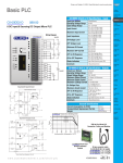
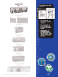
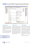
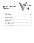
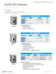
Getting Started
Chapter
1
In This Chapter...
Introduction...................................................................................... 1–2
Conventions Used............................................................................. 1–3
Before you begin............................................................................... 1–4
Step 1: Install Programming Software............................................... 1–5
Step 2: Launch Programming Software............................................. 1–6
Step 3: Create a Project.................................................................... 1–8
Step 4: Compile and Save Project................................................... 1–14
Step 5: Apply Power....................................................................... 1–15
Step 6: Establish PC to PLC Communications.................................. 1–16
Step 7: Write Project into PLC......................................................... 1–24
Step 8: Place PLC in RUN Mode...................................................... 1–25
Step 9: Test Project using Data View Monitor................................. 1–26
Step 10: Y001 Output On?............................................................. 1–27
Additional Training Resources......................................................... 1–28
Chapter 1: Getting Started
1
2
3
4
5
6
7
8
9
10
11
12
13
14
A
B
C
D
Introduction
Purpose of this Manual
Thank you for purchasing the AutomationDirect CLICK PLC family of products. This
hardware user manual provides information that will help you install, set up, program,
troubleshoot, and maintain your CLICK PLC system. The manual includes information
that is critical to the safety of the personnel who will install and use the PLC, and to the
machinery, processes, and equipment controlled by the PLC.
The manual also includes important information about power and signal wiring,
mounting of the PLC, and configuring the PLC system.
About Getting Started
If you are familiar with PLCs in general, then following the simple steps in this first
chapter may be all you require to start being productive using a CLICK PLC system. After
you have completed the steps, your CLICK PLC will be running the ladder logic project
that you programmed. If you are new to the world of PLCs, be sure to read through all of
the chapters in this hardware user manual.
Supplemental Manuals and Other Help
The CLICK Programming Software, C0-PGMSW, can be downloaded free from the
AutomationDirect web site (link shown below under Technical Support). Both this
Hardware User Manual, C0-USER-M, and the Software Installation Guide are free as a
download. The CLICK Programming Software includes searchable online help topics
covering all aspects of the software and instruction set.
Technical Support
We strive to make our manuals the best in the industry. We rely on your feedback to let
us know if we are reaching our goal. If you cannot find the solution to your particular
application, or, if for any reason you need technical assistance, please call us at:
770–844–4200
Our technical support group will work with you to answer your questions. They are
available Monday through Friday from 9:00 A.M. to 6:00 P.M. Eastern Time. We also
encourage you to visit our web site where you can find technical and non-technical
information about our products and our company.
http://www.automationdirect.com
1–2
CLICK PLC Hardware User Manual, 5th Edition – C0-USER-M
Chapter 1: Getting Started
Conventions Used
When you see the exclamation point icon in the left-hand margin, the paragraph to its immediate right
will be a warning. This information could prevent injury, loss of property, or even death in extreme
cases. Any warning in this manual should be regarded as critical information that should be read in its
entirety. The word Warning in boldface will mark the beginning of the text.
When you see the notepad icon in the left-hand margin, the paragraph to its immediate right will be a
special note. Notes represent information that may make your work quicker or more efficient. The word
NOTE: in boldface will mark the beginning of the text.
Whenever the “lightbulb” is shown in the left-hand margin, the paragraph to its immediate right will
provide a special tip. The word TIP: in boldface will mark the beginning of the text.
Key Topics for Each Chapter
The beginning of each chapter will list the key topics
that can be found in that chapter.
Getting Started!
CHAPTER
1
In This Chapter...
Introduction .............................................................................1-2
Purpose of this Manual ....................................................................1-2
About Getting Started! ......................................................................1-2
Supplemental Manuals and Other Help ............................................1-2
Technical Support .............................................................................1-2
Conventions Used ....................................................................1-3
CLICK PLC Hardware User Manual, 5th Edition – C0-USER-M
1–3
1
2
3
4
5
6
7
8
9
10
11
12
13
14
A
B
C
D
Chapter 1: Getting Started
1
2
3
4
5
6
7
8
9
10
11
12
13
14
A
B
C
D
Before you begin...
It is recommended that the following items be available to make this short step-by-step
introduction to the CLICK PLC go smoothly.
CLICK 24 VDC Power Supply
C0-00AC or C0-01AC
CLICK PLC unit
Other 24 VDC Power Supply
Example: PSP24-60S
or
PC Running
Windows XP, Vista,
Windows 7 or Windows 8
CLICK
Programming Software
C0-PGMSW
Based on your CLICK PLC,
One of the cables shown below:
Ethernet Cat5 Cable
PC with USB port to
Panel Programming
Cable Assembly
EA-MG-PGM-CBL
Not available from ADC.
CD-ROM or Free download @
Screwdriver
DN-SS1
http://support.automationdirect.com/
products/clickplcs.html
AC Power Cord
Wire Strippers
DN-WS
Hookup Wire
Not available from ADC.
1–4
PC Programming Cable
D2-DSCBL
PC requires RS-232 port.
CLICK PLC Hardware User Manual, 5th Edition – C0-USER-M
Chapter 1: Getting Started
Step 1: Install Programming Software
1.) If you you have the programming software on CD, insert the CD in the computer drive and
follow the instructions. Otherwise, download the free CLICK Programming Software,
C0-PGMSW, from the following Automationdirect.com web site:
http://support.automationdirect.com/products/clickplcs.html
2.) Unzip the downloaded ZIP file.
3.) Double click Install.exe. The CLICK PLC Programming Software splash screen should appear
after a short time.
4.) Click on the splash screen’s Install Software button and follow the dialog boxes.
5.) If you intend to communicate via USB ports on your personal computer using cable
EA-MG-PGM-CBL, click on the Install USB Drive button. Follow the dialog boxes. You can
install the USB driver either before or after the software is installed.
Install USB Driver Button
NOTE: For additional details, see the CLICK
Software Installation Guide, C0-PGMSW-SIG,
included in the ZIP file. (file name: Click_
software_installation.pdf)
CLICK PLC Hardware User Manual, 5th Edition – C0-USER-M
1–5
1
2
3
4
5
6
7
8
9
10
11
12
13
14
A
B
C
D
Chapter 1: Getting Started
1
2
3
4
5
6
7
8
9
10
11
12
13
14
A
B
C
D
Step 2: Launch Programming Software
After installing the CLICK Programming Software, C0-PGMSW, choose one of three
methods to launch the software. Double click the desktop CLICK icon or, from the PC’s Start
menu, slide the mouse pointer through the menus (Start > All Programs > AutomationDirect
> CLICK Ver2.00 > CLICK Programming Software) and click the CLICK Programming
Software selection or, simply click the icon on the Quick Launch bar. See examples below.
The CLICK Programming Software will start up and display the Main Window as shown on
the next page.
NOTE: The recommended minimum screen size for the CLICK Programming Software is 1024 X 786 pixels.
1–6
CLICK PLC Hardware User Manual, 5th Edition – C0-USER-M
Chapter 1: Getting Started
Step 2: Launch Programming Software (cont’d)
The Main Window is divided into Menus, Toolbars, and Windows that work together to make
project development as simple as possible. See the software’s online help for additional details.
Click on the “Start a new project” graphic in the Startup dialog box. The Select a CPU
Module window opens.
Select the CLICK PLC unit that you will use for the ladder logic example that follows.
CLICK PLC Hardware User Manual, 5th Edition – C0-USER-M
1–7
1
2
3
4
5
6
7
8
9
10
11
12
13
14
A
B
C
D
Chapter 1: Getting Started
1
2
3
4
5
6
7
8
9
10
11
12
13
14
A
B
C
D
Step 3: Create a Project
In this step, the project shown below is created by entering the ladder logic program in
the order that follows.
Rung #1
Place the Box Cursor on the first position on Rung #1, as shown below. From
the Instruction List, click & drag a Contact (NO) into this box. Enter C1
into the Bit Memory Address text box of the Contact Normally Open dialog
box that pops up and click OK. A normally open contact labeled C1 will be
placed in the beginning of Rung #1.
The Box Cursor will move to the next available location.
Proceed to the next page to continue construction of Rung #1.
1–8
CLICK PLC Hardware User Manual, 5th Edition – C0-USER-M
Chapter 1: Getting Started
Step 3: Create a Project (cont’d)
Rung #1 (cont’d)
The Line creation tool is used to add an additional normally open contact in parallel with the
C1 contact. Click on the Line creation tool icon located on the Edit toolbar. A blue line will
appear, showing the direction of the new line. The Line pen is used to redirect the new line.
Move the mouse pointer to the end of the new line (arrow) until the mouse pointer
becomes a hand with a pointing index finger. Click on the line’s arrow.
Additional new lines are shown in blue. Move the mouse pointer to the end of the new
line that extends to the left and click.
There is now a parallel path around the C1 contact that was first entered as shown here.
Proceed to the next page to continue construction of Rung #1.
CLICK PLC Hardware User Manual, 5th Edition – C0-USER-M
1–9
1
2
3
4
5
6
7
8
9
10
11
12
13
14
A
B
C
D
Chapter 1: Getting Started
1
2
3
4
5
6
7
8
9
10
11
12
13
14
A
B
C
D
Step 3: Create a Project (cont’d)
Rung #1 (cont’d)
Next, click on the Reset Line Mode icon located on the Edit toolbar (Esc key has the same
function as the Reset Line Mode). The Box Cursor will move to the newly created path. If not,
position the Box Cursor over the new path to get ready for the next instruction.
NOTE: There is also a Line Erase tool icon next to the Line tool icon on the Edit toolbar that is used to
erase any of the lines that were created using the Line tool. Also, to exit the Line or Line Erase function,
click on the Reset Line Mode icon on the Edit toolbar. All of the Line type tools are also available under the
Edit drop down menu.
NOTE: Lines to form parallel paths in the ladder logic can also be created with the use of the cursor keys in
conjunction with the CTRL key on the PC’s keyboard.
Proceed to the next page to continue construction of Rung #1.
1–10
CLICK PLC Hardware User Manual, 5th Edition – C0-USER-M
Chapter 1: Getting Started
Step 3: Create a Project (cont’d)
Rung #1 (cont’d)
From the Instruction List, click & drag a Contact (NO) into th Box Cursor. Enter C2 into
the Bit Memory Address text box of the Contact Normally Open dialog box that pops up and
click OK. A normally open contact labeled C2 will be placed in parallel with the C1 contact.
Next, place the Box Cursor on the NOP coil at the far right of Rung #1. NOP stands for No
Operation and is a place holder in the ladder logic Coil Area. Click & drag a Timer from the
Instruction List into this location. Within the Timer dialog box, enter T1 into the Timer
Number text box, the value 5 into the Set Point, and select sec for the timing Unit. The Timer
dialog box shows a Timing Chart that graphically represents the function of the ON Delay
Timer, and also shows a selection for an alternative OFF Delay Timer mode of operation.
Leave the Delay Setting at ON Delay Timer and the Current Value Option set for the first
selection. Click OK. A timer labeled T1 will be placed at the end of Rung #1.
Proceed to the next page to enter Rung #2.
CLICK PLC Hardware User Manual, 5th Edition – C0-USER-M
1–11
1
2
3
4
5
6
7
8
9
10
11
12
13
14
A
B
C
D
Chapter 1: Getting Started
1
2
3
4
5
6
7
8
9
10
11
12
13
14
A
B
C
D
Step 3: Create a Project (cont’d)
Rung #2
Place the Box Cursor at the beginning of Rung #2. From the Instruction List, click and drag a
Contact (NO) into this box. Enter T1 into the Bit Memory Address text box of the Contact
Normally Open dialog box that pops up. Click OK. A normally open contact labeled T1 will
be placed in the beginning of Rung #2.
Next, place the Box Cursor on the NOP coil at the far right of Rung #2. Click and drag an
OUT from the Instruction List into this location. Within the Out dialog box, enter Y001 into
the Bit Memory Address: text box. Click OK. An out coil labeled Y001 will be placed at the
end of Rung #2.
Rung #3
Finally, place the Box Cursor on the NOP coil at the far right of Rung #3. Click and drag an
END from the Instruction List into this location. An END instruction indicates the last part
of the main ladder logic program. You have created your first project!
1–12
CLICK PLC Hardware User Manual, 5th Edition – C0-USER-M
Chapter 1: Getting Started
Step 3: Create a Project (cont’d)
Program Execution
The following is an explanation of how the CLICK PLC executes the ladder logic program that
was just entered.
The CLICK PLC executes the ladder logic program instructions, starting with Rung #1, from
left to right, and then proceeds to execute the next rung in the same fashion, carrying on
through all of the rungs in sequential order. The 6 instructions (a, b, c, d, e and f) in the above
ladder logic program are executed in the following order.
Explanation of the Program Execution
O (Normally Open) Contact: Address C1 and C2 are assigned to a NO Contact. C1 and
N
C2 are internal control bits. The internal control bits are 1 bit memory and hold the status
of ON or OFF. The contacts are enabled when the status of C1 or C2 is ON.
Timer: This instruction is used to delay an action once it is enabled. The CLICK PLC
unit can use up to 500 timers (T1 to T500) in a project. In this ladder logic program,
timer T1 is assigned. The Timer instruction is set up as an ON Delay Timer with a
5 second set point. That is, the timer status bit T1 output coil turns on 5 seconds after the
enable input of the Timer instruction turns on.
This is a NO Contact addressed as T1 and whose status is controlled by Timer T1. The
contact is enabled when Timer T1 output coil becomes true after the 5 second delay.
OUT: This is an output coil addressed as real world output Y001, which happens to be the
first output on the CLICK PLC unit. It becomes active when the T1 NO Contact in this
rung becomes enabled.
END: This is the END of the ladder logic scan, and causes the scan to start at the
beginning.
CLICK PLC Hardware User Manual, 5th Edition – C0-USER-M
1–13
1
2
3
4
5
6
7
8
9
10
11
12
13
14
A
B
C
D
Chapter 1: Getting Started
1
2
3
4
5
6
7
8
9
10
11
12
13
14
A
B
C
D
Step 4: Compile and Save Project
Syntax Check (Compile)
Next, you need to compile the ladder logic program. Compiling
the program is done with the Syntax Check function. The
ladder program is checked for problems and other conditions
that may prevent the ladder program from executing correctly.
The results of the Syntax Check are displayed in the Output
Window at the bottom of the Main Window as shown below.
From the Program drop down menu, select Syntax Check as
shown below, or press the F8 function key on your keyboard, or
click on the Syntax Check icon located on the Program Toolbar.
If everything in the program checks out correctly, then the Output Window will indicate
0 error(s) as shown in the following example.
If there are any errors, they will be indicated in the Output Window. For quicker
troubleshooting, double click on any particular error in the Output Window and be taken
directly to the rung and instruction that may be causing the error. The following is an example
of an error.
Save Project
It is always a good practice to save your project at this point.
From the File drop down menu, select Save Project, as
shown here, or click on the Save Project icon located on the
File Toolbar.
Enter the File Name for your
project in the Save As dialog
box. You can also browse to
the folder that you want the
project saved under. Click
Save.
1–14
CLICK PLC Hardware User Manual, 5th Edition – C0-USER-M
Chapter 1: Getting Started
Step 5: Apply Power
The CLICK PLC system works with 24 VDC power. There is a small terminal block on the
bottom of the CLICK PLC unit. Wire the 24 VDC output from a CLICK power supply, or
a properly sized and rated 24 VDC power supply such as AutomationDirect’s RHINO series,
to the bottom terminal block (See Chapter 2: Specifications for power supply specifications.)
EITHER
Using a CLICK 24 VDC Power Supply.
24V
0V
24V
0V
G
G
OR
Using an alternate 24 VDC Power Supply.
24V
0V
24V
0V
G
G
Once you wire and power up the power supply, confirm
the PWR indicator (Green LED) on the CLICK PLC
unit is on.
If the PWR indicator is not on, check the voltage on the
terminal block with a voltage meter. If you measure 24
VDC on the terminal block, the CLICK PLC unit may
be defective. Please try another one or contact us for a
replacement.
PWR
Indicator
CLICK PLC Hardware User Manual, 5th Edition – C0-USER-M
1
2
3
4
5
6
7
8
9
10
11
12
13
14
A
B
C
D
C0-00DD1-D
1–15
Chapter 1: Getting Started
Step 6: Establish PC to PLC Communications
1
2
3
4
5
6
7
8
9
10
11
12
13
14
A
B
C
D
Next, connect a personal computer (PC) to Port 1 or Port 2 on the CLICK PLC unit. You
can use one of the following communication ports on the CLICK PLC unit for programming.
C0-01DD1-D
C0-11DD1E-D
C0-11D
D1E--D
D
C1
1
X1
X2
2
PWR
Port 1 (RS-232)
RUN
ERR
Port 1 (Ethernet)
PORT1
TX1
Port 2 (RS-232)
RX1
TX2
RX2
PORT2
PORT3
Port 2 (RS-232)
PWR
RUN
R
UN
RUN
ERR
TX3
X6
6
LNK/ACT
ETHER
NET
100MBIT
X7
7
X8
8
C3
3
PORT2
Y1
TX2
Y2
2
RX3
Basic PLC
Standard PLC
Analog PLC
Y3
3
RS-232
RS
232
PO
ORT3
PORT3
TX3
TX
X3
RX
X3
RX3
C2
2
X5
5
PORT1
RX2
RS-485
X3
3
X4
4
STOP
S
TOP
Y4
4
RS-485
RS-485
485
5
+
_
LG
G
C4
4
Y5
5
Y6
6
+V
V
Ethernet Basic PLC
Ethernet Standard PLC
NOTE: Port 2 (RS-232) setup can be changed by the customer. We recommend using Port 1 for
Programming.
1–16
CLICK PLC Hardware User Manual, 5th Edition – C0-USER-M
Chapter 1: Getting Started
Step 6: Establish PC to PLC Communications (cont’d)
Using an RS-232 port for Programming
EITHER
If a USB port is available on the PC, then use an AutomationDirect USB to RS232 PC to Panel
Programming Cable Assembly, EA-MG-PGM-CBL, to connect between the USB port on the
PC and the RJ12 connector on the PLC’s Port 1.
CLICK PLC
PC to Panel Programming
Cable Assembly
(Includes serial & USB cables)
EA-MG-PGM-CBL
Using a PC USB Port.
PC
Serial
Cable
USB
Cable
USB to RS232
Converter
OR
If a 9-pin RS-232 serial communications port is available on the PC, then use an
AutomationDirect PC Serial Programming Cable, D2-DSCBL, to connect between the 9-pin
port on the PC and the RJ12 connector on the PLC’s Port 1.
Using a PC Serial Port.
CLICK PLC
PC
PC Serial
Programming Cable
D2-DSCBL
NOTE: Port 1 (RS-232) on the CLICK PLC unit is designed as the primary programming port. The port has
fixed communication parameters, so you can always connect the programming software to the CLICK PLC
unit through the port without any configuration changes.
CLICK PLC Hardware User Manual, 5th Edition – C0-USER-M
1–17
1
2
3
4
5
6
7
8
9
10
11
12
13
14
A
B
C
D
Chapter 1: Getting Started
1
2
3
4
5
6
7
8
9
10
11
12
13
14
A
B
C
D
Step 6: Establish PC to PLC communications (cont’d)
Once we have a communications cable connected between
a port on the PC and PORT1 on the CLICK PLC, we
need to select the PC COM port that is connected to the
CLICK PLC. From the PLC drop down menu, select
Connect as shown to the right, or click on the Connect
icon located on the PLC Toolbar.
The Connect to PLC dialog box will be displayed.
Under the COM Port No.: drop down list, select the
communications port that is connected to the CLICK
PLC Port 1.
If you are connecting the programming cable to Port 1 on
the CLICK PLC unit, you do not need to change any of the
parameters, just click the Connect button. The software
should start to immediately connect to the CLICK PLC.
If you cannot connect the software to the CLICK PLC, try
the above procedure one more time and keep watching the
TX1 and RX1 indicators on the CLICK PLC unit.
If the RX1 is not blinking, it means the CLICK PLC unit
is not receiving any data from the programming software.
Check to make sure you have selected the correct PC COM
Port, and also check the cable connections.
1–18
CLICK PLC Hardware User Manual, 5th Edition – C0-USER-M
Chapter 1: Getting Started
Step 6: Establish PC to PLC Communications, (cont’d)
1
2
3
4
5
6
7
8
9
10
11
12
13
14
A
B
C
D
NOTE: If using the USB to RS232 converter, and you are not
sure to which PC COM Port the USB port is assigned, click the
Detail... button next to the COM Port drop down list to identify
it. The screen to the right shows the Koyo USB-Serial Com
Port device assigned to COM3. Select it and click OK.
Proceed to page 1-24
CLICK PLC Hardware User Manual, 5th Edition – C0-USER-M
1–19
Chapter 1: Getting Started
1
2
3
4
5
6
7
8
9
10
11
12
13
14
A
B
C
D
Step 6: Establish PC to PLC Communications, (cont’d)
Using Ethernet Port for Programming
You can connect your PC to the CLICK PLC via an Ethernet switch/hub or directly to the
Ethernet port. You can use a straight or crossover Ethernet cable.
Once we have communications cable(s) connected
between the Ehernet port on the CLICK PLC and the
Ethernet port on the PC, we are ready to connect the
CLICK Programming Software to the CLICK PLC.
From the PLC drop down menu, select Connect as
shown to the right, or click on the Connect icon located
on the PLC Toolbar.
1–20
CLICK PLC Hardware User Manual, 5th Edition – C0-USER-M
Chapter 1: Getting Started
Step 6: Establish PC to PLC Communications, (cont’d)
Select Ethernet as the Port Type. Select the network adapter that you want to connect to
the CLICK PLC, if you have more than one network adapter on your PC. The CLICK
programming software automatically scans the CLICK PLC units in the LAN connected to
the network adapter and displays them in the list as shown below.
To connect the CLICK programming software to the CLICK PLC, both the PC and the
CLICK PLC must be in the same subnet. In the above Connect to CLICK PLC window,
the IP Address of the PC is ‘10.11.0.48’ and the Subnet Mask is ‘255.255.0.0’. You can
determine the subnet that your PC is located in by applying the AND operation between the
IP Address and the Subnet Mask.
Example:
IP Address = 10.11.0.48
AND
Subnet Mask = 255.255.0.0
||
Subnet = 10.11.0.0
CLICK PLC Hardware User Manual, 5th Edition – C0-USER-M
1–21
1
2
3
4
5
6
7
8
9
10
11
12
13
14
A
B
C
D
Chapter 1: Getting Started
1
2
3
4
5
6
7
8
9
10
11
12
13
14
A
B
C
D
Step 6: Establish PC to PLC Communications, (cont’d)
To match the subnet setup of the CLICK PLC to the
subnet that the your PC locates in, select the CLICK
PLC unit in the list and click the Edit button under the
list. The Edit window opens.
Next, the new IP Address needs to start with ‘10.11’ to match the subnet of the PC. The
following 2 numbers however, can be any number as long as the new IP Address is unique in
the LAN. In the window here, the IP Address was changed to ‘10.11.0.24’.
Click the OK button to continue. The new IP Address setup is sent to the CLICK PLC.
Your PC and the CLICK PLC locate in the same subnet now. Click the Connect button on
the bottom to connect the CLICK programming software to the CLICK PLC.
1–22
CLICK PLC Hardware User Manual, 5th Edition – C0-USER-M
Chapter 1: Getting Started
Step 6: Establish PC to PLC Communications, (cont’d)
If you are trying to connect the CLICK Programming Software to a new CLICK PLC or an
older CLICK PLC that was reset to the factory default, you will see the following pop-up
message once communication has been established with the CLICK PLC. This is because
there is no user project in the CLICK PLC currently. Click the OK button to close the
message and proceed to the next step.
If you are trying to connect the CLICK Programming Software to a CLICK PLC that already
has a user project, the following Connect dialog box will appear.
It is not unusual that the project opened in the programming software will not match the
project that resides in the PLC. The dialog box gives you a choice to either read the PLC’s
project for viewing purposes, but at the same time allowing the project opened in the software
to still be saved, or not read the project in the PLC.
For the Getting Started exercise, click the radio button for the “Don’t read the project from
the PLC” and click OK. Proceed to the next step which will allow the created project to be
written into the CPU memory.
CLICK PLC Hardware User Manual, 5th Edition – C0-USER-M
1–23
1
2
3
4
5
6
7
8
9
10
11
12
13
14
A
B
C
D
Chapter 1: Getting Started
1
2
3
4
5
6
7
8
9
10
11
12
13
14
A
B
C
D
Step 7: Write Project into PLC
The next step is used to transfer the project that was created into the
CLICK PLC. From the PLC drop down menu, select Write Project
into PLC as shown to the right, or click on the Write Project into
PLC icon located on the PLC Toolbar.
The following dialog box is displayed.
The dialog box displays the information for the Project that is currently opened in the
programming software (PC) on the left side. The dialog box also displays the information for
any Project that may be stored in the CLICK PLC unit (PLC) on the right side.
Click OK to write the project data from the PC to the CLICK PLC unit.
The Writing... progress window will open to allow verification that the Project is being written
to the CPU. When finished, a Transfer Completed message will be displayed. Click OK to
continue.
1–24
CLICK PLC Hardware User Manual, 5th Edition – C0-USER-M
Chapter 1: Getting Started
Step 8: Place PLC in RUN Mode
The next step is to place the CLICK PLC into its Run mode so that
the ladder logic program will execute. From the PLC drop down
menu, select PLC Modes... as shown to the right, or click on the
PLC Modes... icon located on the PLC Toolbar.
The PLC Modes dialog box is displayed.
Click the radio button for RUN and then click the OK button. The CLICK PLC is now in
Run mode and executing your ladder logic program.
NOTE: The PLC Modes dialog box can also be accessed by clicking on the Connection status (Offline/Run/
Stop) indicator button that is located on the toolbar.
CLICK PLC Hardware User Manual, 5th Edition – C0-USER-M
1–25
1
2
3
4
5
6
7
8
9
10
11
12
13
14
A
B
C
D
Chapter 1: Getting Started
1
2
3
4
5
6
7
8
9
10
11
12
13
14
A
B
C
D
Step 9: Test Project using Data View Monitor
In this next step, use the Data View Monitor to test the ladder logic
program by manually overriding the status of the internal C1 bit that
was programmed. The purpose of this will be to have the C1 bit
enable Timer T1. From the Navigation window on the left side of the
development screen, select the Program tab, open the Data View folder
under Monitor and double click on DataView1.
The Data View window is displayed.
Click the Edit button and type in C1 as the Address as shown below.
Double click the ON button in the New Value column. The Current Value of the C1 bit
changes from OFF to ON. Go to Step 10: “Y001 Output On?”
1–26
CLICK PLC Hardware User Manual, 5th Edition – C0-USER-M
Chapter 1: Getting Started
Step 10: Y001 Output On?
CLICK PLC output Y001 (labeled Y1 on the PLC unit) will turn on 5 seconds after you write
the ON state to the C1 bit using Data View in the Edit mode.
Y001
ON
If you missed viewing the transition of the Y001 status LED from OFF to ON, write an OFF
state to the C1 bit and then an ON state in the Data View Monitor to do it again.
NOTE: Also, try changing the status of the internal C2 bit. The results should be the same because the C2
bit is in parallel with the C1 bit. The ladder logic reads: “Enable timer T1, if either C1 or ‘C2 is true.”
Congratulations!
You have now learned how to create, compile and transfer a ladder logic project to a CLICK
PLC, and then run and test the project. There are additional instructions available for the
CLICK PLC. Please refer to the programming software online help topics for details on these
instructions.
Again, thank you very much for using the CLICK PLC system.
CLICK PLC Hardware User Manual, 5th Edition – C0-USER-M
1–27
1
2
3
4
5
6
7
8
9
10
11
12
13
14
A
B
C
D
Chapter 1: Getting Started
1
2
3
4
5
6
7
8
9
10
11
12
13
14
A
B
C
D
Additional Training Resources
In addition to this Getting Started chapter, there are other resources we recommend to learn
more about using your CLICK PLC system.
Automationdirect.com Online Tutorial Site - http://learn.automationdirect.com/
Learn.AutomationDirect.com is an online streaming tutorial site offering on-demand video
tutorials on a wide range of practical industrial products, including the CLICK PLC.
Automationdirect.com Web Seminars - http://www.automationtalk.com/
Automationtalk.com has live and recorded webinars on many industrial products, including
the CLICK PLC.
1–28
CLICK PLC Hardware User Manual, 5th Edition – C0-USER-M
Chapter 1: Getting Started
Interconnecting Automation Online Training Courses - http://clickplctraining.
com/
Interconnecting Automation offers inexpensive subscription-based online training, including
CLICK PLC training.
Also, a CLICK PLC Trainer is available from this web site.
CLICK PLC Hardware User Manual, 5th Edition – C0-USER-M
1–29
1
2
3
4
5
6
7
8
9
10
11
12
13
14
A
B
C
D