1
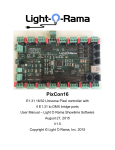
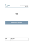
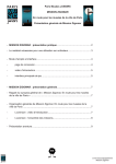
SanDevices E682 Pixel Controller Operating Manual
Oct 21, 2012
Revision History:
Oct 21, 2012 original publication
Introduction
The SanDevices E682 is an evolution of the E68X product line, and is very similar to it’s
predecessor, the E681. The E682 is a controller intended to be used as part of a system
to operate a lighting display that consists of many individual RGB LED pixels. To form a
complete system, one or more E682s are used together with one or more pixel power
supplies, one or more strings or strips of pixels, and a PC equipped with lighting
display software that supports RGB pixels and is compatible with industry-standard SACN,
or E1.31 “DMX over Ethernet” lighting protocol.
The E682 is usually installed near the pixels it controls and their power supply, and
acts as the “bridge” between the pixels and the PC. The E682 receives the lighting
intensity signals from the computer via a network (LAN) connection, and converts them
into a form suitable for operating the actual pixels.
The lighting control software determines what DMX (intensity) values need to be sent to
each color of each pixel. The PC software then forms this data into “packets”, each
packet consisting of the current intensity value for each of up to 510 channels (3
channels for each pixel), and sends these packets out over its Ethernet port. The
packets travel through your local network and eventually to the E682 via its Ethernet
connection. The E682 then converts the DMX intensity values into multiple streams of
data that are sent on to the various strings of pixels. The controller uses it’s
configuration data, which you define via the controller’s web interface, to know how to
reformat each piece of DMX data to route it to the proper pixel in the form that pixel
will understand. So the path is:
Lighting Software -> Network -> E682 -> Pixels
The E682 is available in kit form, as a fully assembled and tested board, or as part of a
complete system including the E682, a power supply, enclosure, and cables (the PS1).
Like all SanDevices products, the E682 is manufactured in the USA.
Feature Summary:
The E682 is a single PC board, approximately 4” x 7”, the mounting hole pattern is
compatible with the “new style” industry-standard Keptel or equivalent CG-1500 enclosure.
DMX data input via the SACN protocol, also known as E1.31, or DMX over Ethernet, using a
100mb Ethernet connection. The E682 presently support up to 6 universes of SACN
channels, which is enough to control more than 1,000 individual RGB pixels. The use of
the SACN protocol allows multiple universes of lighting channels over a single Ethernet
cable, and eliminates the need for multiple DMX ‘dongles’ at the controlling PC.
16 On-board individually-fused pluggable screw-terminal connectors for connecting up to
16 separate pixel strings or strips. No soldering is required.
All pixel strings are powered from the E682, no external pixel power wiring is needed.
The E682 is extremely versatile, with many programmable options, and many pixel types
supported, including 5-bit (software-expanded to 256 dim levels), 7-bit, 8-bit, and 12bit pixels.
The E682 can be configured to operate multiple pixel types (up to 4 simultaneously), and
multiple pixel voltages (up to 2 simultaneously).
The E682 is configured via a built-in web server.
The E682 has a built-in regulated +5VDC output to power a small Ethernet switch
The E682 is most commonly powered from the same power supply that operates the pixels,
but may be powered by a small dedicated power supply (7-24VDC at 300ma) if desired.
Outputs, in groups of 4, can be selected for “balanced” 2-wire operation, to drive
standard wired DMX devices. In many cases this will eliminate the need for separate
hardware to handle traditional wired DMX fixtures.
The E682 supports 8-bit dimming (256 intensity levels) for the LPD6803 pixel type.
Specifications:
Input: E1.31, streaming DMX over Ethernet, multicast format, up to 6 universes, or a
total of 3070 DMX channels.
Output: 16 connectors for pixel strings. The board can control up to 1020 individual
pixels using up to 3060 DMX channels. (The limitation is the number of available DMX
channels, and if some or all of the pixels are to be controlled in groups, then the total
pixel count can be much larger.)
Power: There are two connections for pixel power, allowing the use of two separate pixel
power supplies. This also allows a mix of 5 volt and 12 volt pixels (for example) to be
controlled by a single E682. Each power inlet supplies power to 8 pixel outputs and is
rated to carry up to 32 amps. The E682 itself is typically powered from the right-hand
(clusters 3 and 4) pixel power supply, but may also be powered independently by a power
supply that is capable of providing 7-24 volts DC at about 300ma, connected to J19.
The E682 has a large number of programmable options to allow the board to be used in many
different configurations. Programmable options are set using a web page. This page also
displays operating statistics and the current configuration data.
Supported Pixel Types:
WS2801, WS2811, LPD6803, 180X, GE ColorEffects, TLS3001, CYT3005, 16716, 981X, and Native
DMX mode. The E682 supports 8-bit dimming (256 intensity levels) for the 5-bit LPD6803
pixels.
Note that many common pixel types are “clones” of others.
WS2811 = 1804
CYT3005 = TLS3001
Some common examples are:
Full Pixel Type List, Supported Pixel Types (E682)
E682 Chip#
Common Type
Also Equivalent To
0
1
2
3
4
5
6
7
8
WS2801
LPD6803
GE ColorEffects
TM1804(fast mode)
SM16716
Native DMX
LPD8806
P981x
TLS3001
WS2803
D705, LPD1101, UCS6909, UCS6912
WS2811, TM1803, TM1809, TM1812, SM16715
HX512A, MY994X and standard wired DMX fixtures
LPD8809
TLS3002, CYT3005
Please note that the above-listed compatibility is believed to be accurate but not all
listed pixel types have been tested to verify the compatibilies listed.
Summary of differences between the E682 and the E681:
Physically, the E682 circuit board is slightly wider. This is to accommodate automated
assembly equipment. The mounting hole arrangement differs also, the E681 mount hole
pattern allows for up to #6 screws and is compatible with the “new-style” CG-1500,
whereas the E681 would only accommodate #4 screws and was compatible with the “old-style”
CG-1500. The clearance between mounting holes and nearby components has been improved on
the E682 as well. Also there is better clearance for inserting the network cable.
Electrically, the E682 uses a newer Ethernet module, the Wiz820IO, which is based on the
W5200 ethernet controller. The E681 (and E680) use the WIZ812 which is based on the
W5100. The W5200 provides 8 hardware Ethernet sockets (simultaneous connections) whereas
the W5100 only provides 4. Currently the E682 supports 6 SACN/E1.31 universes with the
potential to increase to 8 in the future. As a result, all configuration commands that
reference ‘sockets’ will now accomodata up to 6, and the packet statistics area of the
web page now handles data for 6 sockets. With 6 universes the E682 has the ability to
have an always-on web server since the contention between socket #4 and the web server,
that existed on the E680 and E681, has been eliminated by the Ethernet hardware upgrade.
The E682 also has hardware to support balanced outputs, primarily intended for driving
standard wired DMX fixtures or DMX-compatible pixels. A future software update will
allow these outputs to drive Renard controllers as well.
The E682 does not have the selectable 3.3v or 5V signal output feature of the E681. All
signal outputs are always 5 volts. The E682 has 5 LEDs compared to 9 on the E681. The
LEDs that indicated network status on the E681 are not supported by the Ethernet module
used on the E682, although some of that functionality is provided by the LEDs built in to
the Ethernet jack.
Mounting the E682:
The E682 consists of a single circuit board measuring 6.8” x 4.375”(as of rev 1.1). The
earlier Rev 1 boards measured 6.8” x 4.1”. There are (6) .150” mounting holes (suitable
for #6 screws). The coordinates of the 6 mounting holes (assuming the board is viewed
oriented horizontally, with pixel string connectors down, referenced to the top-left
corner of the pc board as (0,0) are:
Rev 1 PCB: (X,Y): (0.15”,0.55”) (5.15”,0.55”) (6.15”,0.55”)
(0.15”,3.55”) (5.15”,3.55”) (6.15”,3.55”)
Rev 1.1 PCB:(X,Y: (0.15”,0.725”) (5.15”,0.725”)
(0.15”,3.725”) (5.15”,3.725”)
(6.15”,0.725”)
(6.15”,3.725”)
If mounting in a custom enclosure it is suggested that all 6 mounting holes be used.
4 of the 6 holes are used if mounting in a standard “CG-1500” enclosure, using #6
sheet metal screws.
When selecting mounting hardware it is important that, if metal hardware is used, screw
heads are sufficiently small (mounting holes are sized for #6 pan-head screws) to insure
that they do not come into contact with any circuit board traces outside of the marked
outline.
Since the E682 must be located near the pixel strings it controls, this will often mean
That the unit is mounted outdoors. It is the user’s responsibility to provide a suitable
enclosure for the E682 and pixel power supplies, that will protect these items from
direct exposure to moisture.
When selecting a mounting location, keep in mind the need for adequate clearance to allow
routing of wires to the pixel power connectors, and for routing the network cable.
When referring to parts locations on the board, using the following illustration, the
assumption is that you are looking at it “right-side up” as shown in the illustrations,
i.e., the large power terminal blocks J18 and J19 will face the bottom.
Figure 2:
E682 Circuit Board Layout
(The highlighted areas in the above illustration indicate user-configurable
jumpers or connection points)
It is recommend that you read this manual in its entirety, plan your pixel layout
once you have familiarized yourself with the capabilities of the E682, and once
you have that plan in mind, proceed with the setup of the E682.
Setting On-Board Jumpers:
There are 2 sets of option jumpers on the E682. In the upper-right hand corner of the
board are the Power Select Jumpers, designated as J21. There are 5 terminal pins numbered
1 through 5. There are three possible configurations of these jumpers in this area,
depending on the power source for the E682. Typically the E682 will be powered from the
pixel power supply attached to J19, since this eliminates the need for a separate power
supply. If the E682 is to be powered from the pixel power source, then set power select
jumpers as follows:
If the pixel power supply connected to J19 is 5 volts, install a jumper between pins 2
and 3 ONLY. For pixel power voltages greater than 5V on J19, install a jumper between
pins 1 and 2, and a jumper between pins 3 and 4.
Finally, if you elect to power the E682 from a separate power supply install a jumper
between pins 1 and 2, and a jumper between pins 4 and 5. In this case connect the
external supply to J17, the upper terminal is positive, and the 2nd terminal from the top
is negative. The external power supply should be from 7 to 24VDC, and capable of
supplying at least 300ma, or 1500ma if powering an ethernet switch from J17. The external
supply should be current-limited or fused at no more than 2 amps.
The E682 contains circuitry to protect the controller’s electronics if a voltage of
greater than 5 volts is connected when the board is jumpered for 5 volt power. This will
result in the 2A fuse blowing. If the 2A fuse is found to be open, double-check the
power select jumpers. The proper configuration of these jumpers is shown on the E682
silk-screen at the extreme right edge of the board.
The other set of configuration jumpers is highlighted in the board layout at the upper
left and is labeled J22. These jumpers, one per output cluster, are installed to enable
the “2-wire balanced” output feature, explained later in this manual.
LED Indicators:
There are 5 LEDs on the E682, located in a line along the left edge. The red STATUS LED
generally indicates that the web server is enabled and will be on during normal
operation. The green STATUS LED generally indicates the presence of received SACN/E1.31
data packets, and will usually glow dimly during normal operation. The 3 yellow POWER
LEDs indicate the presence or absence of different power voltages on the E682 and are
used for troubleshooting. The 2 bottom yellow LEDs indicate the presence of power on the
two pixel power connectors. If either of these LEDs is not lit, it indicates that no
pixel power is being supplied to the corresponding pixel power input. The upper yellow
LED indicate the presence 3.3 volt power, this is the power source that operates the
E682’s electronics. If this LED is not lit the controller is not receiving power, either
the power supply voltage is not present, (this is most likely the case if the “PX 3,4
Pwr” LED is also out), or a blown controller fuse (if the “PX 3,4 Pwr” LED is lit).
Pluggable Resistor Networks:
There are 8 pluggable resistor networks on the E682 located just above the upper row of
pixel string connectors. Each resistor network affects the 2 string connectors
immediately beneath it. These resistor networks may be changed to a different value in
certain situations, depending on pixel type, and/or type and length of pixel wiring.
These networks may also need to be changed for outputs that are driving DMX devices. The
resistor networks must be in place for the E682 to operate.
Fuses:
The E682 uses standard automotive-style “Mini-ATO” fuses. Replacements are readily
available at any auto parts store. The E682 will generally be shipped with 5 amp fuses
installed in the 16 pixel string fuse locations. These fuses protect the pixel string
wiring in the event of a short circuit. The 17th fuse is 2 amps, and protects the E682’s
electronics.
Note that a short circuit at the very end of a pixel string may not blow the fuse, since
in many cases the resistance of the pixel wiring itself limits the current flow from such
a short to a value below the rating of the fuse.
Each of the 16 left-hand fuse positions is designated with the number of the string it
protects. Fuse “F21”, for example, protects the 1st string in cluster #2. The right-most
fuse position is for the power line to the controller circuitry. This fuse should be 2
amps. The most likely cause of blowing this fuse is incorrectly setting the power select
jumpers.
Making Connections to the E682:
There are 3 basic types of connections required for operation of the E682: One or two
pixel power supplies, an ethernet connection to the local LAN, and the pixels themselves.
In certain situation there will also be a connection to the AUX POWER connector, J19,
described later.
Pixel Power Supply Connections:
The E682 must be used in conjunction with an appropriate pixel power supply. The
specifications of the pixel power supply will depend on the type and quantity of pixels
being driven. 5 volt and 12 volt pixels are the most common. If using 2 different
voltages of pixels simultaneously, you will need either 2 separate power supplies, or a
single supply that can supply both voltages.
Power for the pixels is connected to the two large 2-terminal screw blocks on the bottom
edge of the board, designated J18 and J19. The left-hand terminal is marked positive (+)
and the right-hand terminal is negative (-). There is a legend silk-screened on the board
below the terminal blocks.
Power to the left-hand connector, J18, supplies power to the pixel strings connected to
connectors 1-1 through 2-4. Power to J19 powers the pixels on connectors 3-1 through 44, and usually supplies power to the E682 itself as well.
One power supply can power both sides, either by running 2 sets of + and – wires from the
power supply, one to each terminal block (preferred), or by connecting power to one
terminal block and installing a jumper wire between the 2 positive terminals.
Alternatively the E682 can be powered by 2 separate power supplies, one driving each
‘side’ of the board. To know the current requirements of the pixel power supplies, you
need to know the power requirements of each pixel and the total number of pixels. A good
rule of thumb is about 3 amps per 50 pixels.
To power a full load of 16 50-pixel strings, you should have a power supply rated at a
minimum of 50 amps, and use short runs of 12 gauge wire or larger between the power
supply and the board. The negative side of the power supply should be connected to earth
ground by wiring a jumper between the power supply’s GROUND terminal and the V- terminal.
Note: Typically, RGB pixels will operate off of 5 volts or 12 volts, occasionally 24
volts. It is important that you match your power supply to the requirements of your
pixels. The E682 is capable of driving pixels of 2 different voltages at the same
time. It is very important, when using a dual voltage setup, that you do not plug pixels
into a power supply that supplies more voltage than they are rated for. In other words,
don’t plug a 5 volt pixel string into a pixel connector that is wired for 12 volt pixels,
as the pixel string will most likely be destroyed. If in doubt please contact SanDevices
for assistance in selecting a suitable power supply.
Use care when connecting the pixel power supply to insure that the polarity is correct, +
to +, and – to -. Although the E682 contains circuitry to attempt to protect against a
reversed connection, the effective performance of that protection depends on the power
supply being able to shut down in the event of a reverse-polarity type short-circuit
condition. Some power supplies, particularly if there is significant voltage drop in the
power wiring, may not draw enough current to sense the condition as a short and in that
case it is still possible to damage the controller and/or pixels with improper wiring.
Double-check for correct pixel power wiring before turning on the power.
Because pixels are low voltage devices, the pixel power supply must be located near the
E682, preferably within the same enclosure. This usually means that the power supply
will be mounted outdoors. It is the responsibility of the user to insure that both the
power supply and the E682 are properly protected from moisture. Also, when using this
equipment outdoors, ALWAYS power the pixel power supply from a ground fault-protected
receptacle.
Network Connection:
The Ethernet jack on the Ethernet module must be connected to your LAN, or directly
to the LAN card of the PC that will be controlling the pixels. The E682 LAN port is
capable of running at 100mb/sec, and is auto-sensing. A crossover cable is not required
for a direct connection to a PC. Further discussion of network connection will be found
later in this manual.
Pixel Connections:
The pixel strings plug into the 16 4-pin “euro-style” connectors labeled 1-1 through 4-4.
In general, pixel strings can be plugged and unplugged while the system is powered up,
but it is recommended, to reduce risk of damage to pixels, that pixel strings only be
plugged and unplugged while the system is off. If using the GE ColorEffects strings, they
will not function properly if plugged in while the E682 is powered up.
Connecting Pixel Strings to the E682:
Mating 4-pin screw-terminal connectors are supplied with every E682. It is the users
responsibility to make the proper connections from the pixel strings to the connectors on
the E682. The mating connectors are illustrated below:
Depending on the type of pixels being used, there will be either 3 or 4 wires between the
pixel strings and the E682. All pixels have +V (power), ground, and DATA connections.
Some pixels have a CLOCK connection as well. For runs of up to 10 feet or so, 20 gauge
wire is suitable, beyond 10 feet, 18 gauge wire should be used. It is recommended that
the distance from controller to pixel strings be kept as short as possible. There are 2
factors that limit the maximum distance, voltage drop, and degradation of the signal on
the data and clock wires. The maximum allowable distance between the E682 and the pixel
strings will vary depending on pixel type and the type of wire used. Up to 20 feet or so
should be fine, often significantly longer distances are achievable, but beyond 20 feet
or so the configuration should be tested before the final installation is done. Symptoms
of the cabling being too long are dimming or color-shifting of the last pixels in the
string (usually an indication of excessive voltage drop, often correctable by using
heavier wire), or flickering, generally an indication of corruption of the clock or data
signals, sometimes correctable by using a different type of wire, or by using “null”
pixels.
You MUST know the correct color-code used by your pixel strings. This can and will vary
from manufacturer to manufacturer. Wire color is NOT a reliable indication of function.
If in doubt please contact the pixel vendor for clarification. Incorrectly wiring pixel
strings can and will destroy them. Not only must you identify the function of each wire,
but you must properly identify the START end of the pixel string.
If you are using the black 4-wire waterproof cable assemblies from SanDevices or from Ray
Wu, or pixel strings that have those cables pre-attached, the color code for those cables
is as follows:
RED +V
pixel power
GREEN
Data
BLUE
Clock (not used on 3-wire pixels)
BLACK
Ground
If you look at the E682 circuit board, beneath the 1-2 pixel string connector, the
function of each pin position on the pixel connectors is identified. From left to right,
the pins are:
Gnd
Ground.
Clk
This is the clock line, used on some but not all pixel types.
Dta
This is the data line. It is required for all pixel types.
+V
This is the (typically) +5V or +12V power from the terminal block to the string.
If your design layout calls for longer controller-to-pixel distances, the “Null Pixel”
feature may be a work-around. This involves the installation of extra pixels in the
cable run between the E682 and the pixel string. Since each pixel regenerates the data
signals, this is an effective technique if the issue is one of data corruption. If the
issue is voltage drop, possible solutions are heavier wire between pixels and the E682,
or locating the pixel power source closer to the pixels.
Obviously, you need to be 100% sure that your wiring is correct before plugging in a
Pixel string or strip. It is suggested, if yo have the capability to do so, to check
voltages at the ‘string’ end of the connecting cables that you make up to verify that the
proper voltage is on the proper wire, before splicing to the pixel string itself.
Incorrectly wiring of a pixel string may cause irreversible damage to the
pixels.
Using the Auxiliary Power Connector, J17:
J17 is a multi-purpose connector. Typically it is not needed, but it can be used for 2
optional features. If you choose to power the E682 from its own power supply, rather
than from the pixel power source, you would connect that power supply to J17. +V to the
top pin, and GROUND to the 2nd pin from the top. This power supply should provide from 7-24
volts DC, and be rated at a minimum of 300ma. This supply should be externally currentlimited or fused at no more than 2 amps. If the E682 is powered in this manner, Power
Select Jumpers must be installed between pins 1 and 2, and 4 and 5.
The second use of J17 is to supply a +5VDC output. This would typically be used to power
a small Ethernet switch located near the E682. Having a small Ethernet switch near the
controller can simplify the network wiring since, when using multiple controllers, it
eliminates the need to run an Ethernet cable from every controller back to a remote
switch. The ability to power the Ethernet switch from the E682 simplifies wiring, since
it eliminates the need for a separate switch power transformer, and the 120VAC wiring to
it. You must of course choose an Ethernet switch that runs off of +5VDC, at a maximum of
1 amp. The +5V power output is the 3rd terminal from the top of J17, and ground is the
bottom terminal. See the screened legend on the board.
Note that J17 can be used for both functions simultaneously, but in that case be sure to
use an external power supply rated at a minimum of 1.5 amps since it will be powering
both the E682 and the connected Ethernet switch.
J17 Pinout is as follows (top to bottom):
+V In
external power input, +7 to +24 volts DC, if powering the E682 from it’s own
power supply (not generally required)
GROUND
+5V Out
GROUND
This is a power out, to provide +5V, typically used to power a small Ethernet
switch that is mounted in the enclosure with the E682.
Initial Startup:
E682s are shipped with a test pattern enabled, and with a default pixel configuration
consisting of 4 of the most common pixel types. In many cases this allows you to verify
the proper operation of the E682, pixel power supply, and pixels, without requiring a
network connection or a source of SACN/E1.31 lighting data.
When powered up with one or more pixel strings attached, the test pattern will ‘chase’ a
single bright solid-color pixel through a background of dim pixels. The sequence runs
through each of the 1000+ possible pixels, and will take 60 seconds or so to complete a
cycle. Note that the “as-shipped” default configuration is generally for:
Type 2801 pixels on outputs 1-1 thru 1-4
Type GECE pixels on outputs 2-1 thru 2-4
Type 1804 (or WS2811) pixels on 3-1 thru 3-4
Type TLS3001 (or CYT3005) pixels on 4-1 thru 4-4
(If your pixels are of another type you will have to re-configure the E682 to the proper
pixel type before the test pattern feature will work.)
Special note regarding the GE ColorEffects Pixels: The GE pixels are unique in that they
will only operate properly if they are powered up at thae same time as, or before, the
E682 is powered up. If you plug and unplug GE strings with the power on, or if you power
up the controller before powering up the GE pixels, they will not operate correctly.
To configure the controller or to operate pixels with ‘live’ SACN data requires a network
connection. The recommended procedure is to supply power and a LAN connection to the
E682, access the web page to configure the E682 for your particular arrangement of
pixels, then connect pixel strings and test.
There are 2 pushbuttons on the upper edge of the E682, PROG (program), and RESET.
Pressing the RESET button at any time “re-boots” the controller. The PROG button is used
to perform certain operations at start-up, such as forcing the web server to start, or
forcing specific network modes.
LED Activity During Startup:
During startup, after a few seconds of delay, the green status LED will flash one or more
times (typically twice) to indicate the current network configuration:
1 flash: Currently saved IP MODE is DHCP, and an IP address was obtained from a DHCP
server.
2 flashes: Currently saved IP MODE is Static, and the last STATIC IP address saved into
memory page 0 was used.
3 flashes: An IP address was obtained via DHCP, because it was forced by the pushbutton.
4 flashes: An IP address was set as the last saved STATIC IP address, because it was
forced by the pushbutton.
5 flashes: Currently saved IP mode is DHCP, but no DHCP server responded, so the IP
address has been set to 169.254.74.73.
7 flashes: IP address was forced to DHCP by the pushbutton, but no DHCP server responded,
so our IP address was set to 169.254.74.73.
Note that for blink codes 5 and 7 there will be about a 10 second delay before the code
is flashed. During this time the system is waiting for a DHCP server.
After this flash code, the red LED will come on and stay on, indicating that the E682’s
web server is running.
The firmware as shipped will default to an initial static IP address of
192.168.1.206. If an IP address other than this has been assigned at the
factory it will be indicated by a sticker on the CPU chip. If this is
incompatible with your network, see instructions below to force the use of
DHCP at startup.
Forcing a Specific IP Mode at Startup:
It is possible to over-ride the default network configuration, if necessary, using the
on-board program pushbutton. At power-up, (or after restarting by pressing the RESET
button), press and hold the program button. After a few seconds, the red and green status
LEDs will begin flashing on and off together at a rate of one flash per second. To
override, release the PROGRAM button:
After 1 flash, to force the web server to start without affecting the network mode.
normally required since the E682 is almost always configured to have the web server
running continuously.)
(Not
After 2 flashes to bring up the web server, and force the IP mode to be static.
After 3 flashes to bring up the web server, and force the IP mode to be DHCP.
These functions are in place to allow you to communicate with your E682 via a web
browser, regardless of the state it was in. For example, you may have your E682
configured for a static IP address, but you’ve moved it to a new network where that
address isn’t available. Or perhaps it’s configured for a static IP, but you don’t know
what that IP address is. Or perhaps in your configuration you have disabled the web
server.
Using the over-ride option at startup, you can force your E682 to enable its web server,
and you can force it to get an address via DHCP, or force it to the static IP address
of 169.254.74.73. Then can you access its configuration page with your browser, change
the configuration, and save it.
For the initial setup of an E682, connect the E682 to an unused wired LAN port on your
router. You can also use an available port on an Ethernet switch if your network
configuration includes switches. Basically you want the E682 on the same network that
your PC is on.
Once that’s done, and the E682 is powered up, try accessing the E682’s web page by
typing: 192.168.1.206 into the address bar of your web browser. If your network uses
192.168.1.X addresses the E682’s web page should appear.
If it doesn’t, then the most likely cause is that your network uses some other address
range. Most Linksys routers will use 192.168.1.X, D-Link and Netgear often use
192.168.0.X.
you will need to use the over-ride feature if your local network does not use 192.168.1.X
addresses:
Connect an Ethernet cable directly between a PC and the E682. If there is a wireless
connection to the PC it must be disabled. Reboot the PC. With the E682 powered on,
press AND HOLD the PROG button. While holding PROG, press and release RESET. Continue
to hold the PROG button pressed, and after a few seconds you will see the red and green
LEDs flash on and off together. Wait until the 3rd on/off cycle has completed, then
release the PROG button (after the LEDs go off for the 3rd time, but before they come on
for the 4th time).
Since no DHCP server will be found by the E682 or by the PC, they will both have assigned
addresses in the 169.254.x.x range. Wait until the E682 completes it’s startup as
indicated by the red LED being steady on. Now start up the PC’s web browser; you should
get an error page rather than your usual default page since there is no internet
connection to the PC. Now type 169.254.74.73 into the address bar of your browser and
press ENTER. This should bring up the E682’s web page. From there, you can use the system
configuration commands described later, to reconfigure the E682 to use a static IP
address that is available in your network.
It is recommended that you assign each E682 a permanent static IP address on your
network. That way you won’t have to access your router to find out what the IP address
of a particular unit is. Although typically the IP address assigned by your router with
DHCP will be the same every time you start up the E682, it’s possible that it could
change from time to time. Also please be aware that at this time the E682 does not
support “renewing” of DHCP addresses. Again, in the vast majority of cases this
shouldn’t cause any issues, however the recommended practice is to use DHCP only for
initial access to the E682, then to reconfigure it to use a static IP address.
The procedure to select an appropriate static IP address is beyond the scope of this
document. Briefly, on a typical network that uses IP addresses beginning with “192”, the
first 3 number of every IP address will be the same, only the last varies, so we’ll just
refer to the addresses on the lan by the value of the last number. Typically your router
will use “1” and 255 and 0 aren’t allowed. You also need to avoid the range of IP
addresses that your router assigns automatically via DHCP, see your router’s setup pages
to learn which addresses these are. The default IP address of 192.168.1.206 is usually
safe. If you have multiple E682s it is suggested that each one be assigned the next
available IP address.
Configuring the E682 to operate with your pixels:
Before you can program the E682 to operate your pixels, you’ll need to plan the pixel
layout; in other words which types and lengths of pixels will attach to which connector
on the E682. In order to determine how to attach your pixels, it’s important to
understand how the E682’s pixel outputs are organized. There are 16 pixel string
connections. These are divided up in clusters, and there are 4 clusters of 4 connectors
each for a total of 16 strings. The first digit of each connector is the cluster number
(1-4) and the second digit is the number of the string within that cluster (also from 1
to 4).
It is important to know that the left-hand pixel power connector (J18) supplies power to
the 8left-hand string connectors (clusters 1 and 2), and the right-hand pixel power
connector (J19) supplies power to the 8 right-hand string connectors (clusters 3 and 4).
If you are using 2 different voltages of pixels, you MUST make sure that each pixel
string is plugged into the proper ‘side’ of the E682.
The significance of clusters, is that all string plugged into the same cluster MUST be
identical in many ways, since many of the E682s programmable options are done “per
cluster”. For example, every string in a given cluster must use the same type of
controller chip. Please keep this in mind when planning how your strings will be
organized. The concept of a ‘cluster’ of strings will become clearer when we look at how
the E682 is configured. Also note that starting DMX addresses are assigned by cluster. In
other words you tell the board what the DMX address will be for the 1st pixel on a cluster,
and all of the other pixels in that cluster will follow in order.
In most cases the capabilities of the board will be more than adequate, but bear in mind
that not every configuration is possible. For example, if you want to use 5 volt 6803s,
12-volt 6803s, 5-volt 2801s, 5-volt 1804s, and 5-volt GE pixels all at the same time, you
can’t do it, because that’s 5 different pixel types, each would require its own cluster,
and we only have 4 clusters available.
Another example would be a configuration consisting of 5 volt 2801s, 12 volt 1804s, 12
volt TLS3001s, and 12 volt 2801s. That’s only 4 different types, but that configuration
won’t work because the pixel voltages are split as 2 clusters each, and our example
requires 3 clusters at 12 volts, and 1 cluster at 5 volts, which can’t be done.
Some guidelines on planning the pixel configuration:
Plan on connecting pixel strings in order, beginning with the first available connection
with the proper voltage. Strings that must light sequentially, in other words typically
all of the strings in a given display element, such as a mega-tree, should be plugged
into consecutive connectors, possibly spanning more than one cluster.
Also please keep in mind that a single E682 can control a maximum of 1,020 individual
pixels, or groups of pixels. Understanding pixel grouping is important because it can
allow your total number of pixels to be significantly larger than 1,020. For example, if
some elements of your display don’t require individual control of every single pixel, by
grouping pixels you can reduce the number of DMX channels needed for that display
element, freeing up channels for another display element that perhaps does require
control of every pixel.
Using grouping, you can have a single set of 3 DMX channels control as many consecutive
pixels as you like, a few, many, even an entire string or multiple strings. For example,
if you’re putting 300 pixels on your roofline, but you can get by with controlling them
in groups of 4 pixels (say 1 linear foot of pixel string), then you have ‘saved’ enough
DMX channels to control 225 more pixels or pixel groups. Or if you have a wreath, candy
cane, etc that will always light a solid color, you can control all of those pixels with
just 3 DMX channels.
Once you have a plan, you’re ready to access the E682s built-in web server to enter your
configuration information. Configuration is pretty easy, so if you get started and
realize you need to re-think your arrangement, it’s no big deal.
Accessing the Web Configuration Page:
Please be familiar with the information listed earlier regarding IP addressing,
particularly “Forcing a Particular IP Mode at Startup”. Using the techniques described
there, you should be able to know the IP address of your E682, either from your router’s
DHCP client table, or if no DHCP it’ll be 169.254.74.73.
Make sure the red status LED stays on after the startup sequence. If it doesn’t you’ll
need to use one of the over-rides to force the web server to come on. You can’t access
the board with your browser if the red status LED is off.
Type the E682s IP address into your web browser’s address bar and press ENTER. This
should being up a web page similar to this one:
SanDevices E1.31 Pixel Controller Model E682-6
CPUs Used: Main
E1.31 TIMER Array PixA1 PixA2 PixA3 PixA4
Current Network Mode is: Normal STATIC
IP Address: 192.168.001.206 Subnet Mask: 255.255.255.000 Gateway: 192.168.001.001 DNS Server: 192.168.001.001
Mac Adrs: 4A:49:4D:7B:5F:80
System Up-Time: 0000:00:10 Firmware Version: 2.044
Web Timeout in: ---
E1.31 Packet Statistics:
Socket s1
Universe Number
1
Packets Received
344
Sequence Errors
0
Invalid Packets
0
Global Configuration:
Static Network Information:
IP Address: 192.168.001.206
Socket s2
2
344
0
0
Socket s3
3
343
0
0
Subnet Mask: 255.255.255.000
Socket s4
4
344
0
0
Socket s5
5
344
0
0
Gateway: 192.168.001.001 DNS Server: 192.168.001.001
WEB Server Socket: 8 (DEDICATED)
Last Firmware Update Status: None Tried
Default IP Mode: STATIC Web Srvr Mode: Boot+Auto
No Data Timeout: Disabled
Pixel String Configuration:
Cluster# Strings Chip
Pixels
1
4
1804(F) 050
2
4
1804(F) 050
3
4
WS2801
050
4
4
WS2801
050
Current Page is: 0
Grp
001
001
001
001
Str Len
0050
0050
0050
0050
RGB
RGB
RGB
RGB
RGB
Socket s6
6
0
0
0
DMX Address Range
s1-001 thru s2-090
s2-091 thru s3-180
s3-181 thru s4-270
s4-271 thru s5-360
Reverse
NNNN
NNNN
NNNN
NNNN
Test Pattern: 00
Zigs Null Pixels
0000
0-0-0-0
0000
0-0-0-0
0000
0-0-0-0
0000
0-0-0-0
Refresh Gamma
0245
0245
0212
0212
Command:
Note: The illustrated screen capture is for firmware version 2.044 for a model E682
controller. Later firmware versions may differ.
Note: The E682s web page is ALWAYS static, in other words it NEVER updates by itself.
It will stay as-is until you either hit refresh type in a command or hit “refresh” which
is the same as re-typing the previous command. The times and statistics shown on the page
are as of the last time the page was displayed.
What’s Displayed on the Web Page:
First we’ll talk about the information that you see on the web page, and what every entry
means. Then we’ll talk about the commands that you can enter to change that information.
First the controller is identifying itself as a model E682, the -6 means that it will
control up to 6 universes of pixels (each universe is equivalent to 170 pixels).
The “CPUs Used” line is primarily diagnostic information and can be ignored.
The line beginning with “Current Network Mode is” displays information about the current
network connection: the IP address, the subnet mask, the gateway, and the DNS server. If
this is a STATIC IP, this will be from information that was previously saved in the E682s
memory, if this is a DHCP address, it will be information that was assigned by the DHCP
server on your network. Network mode will be “Normal” or “Forced”, followed by “Static”
or “DHCP”, and optionally, “Failed”. Normal means the mode, static or DHCP, was selected
based on the saved configuration. Forced means the current network mode was forced using
the PROG pushbutton at startup, over-riding the stored setting. DHCP or Static shows the
type of address currently in use, and failed means the E682 tried to use DHCP, but no
server was found.
DHCP server, if not 0.0.0.0, is the IP address of the server that gave the E682 an IP
address, usually it will be the IP address of your router. MAC address is this boards
unique MAC address, it will always begin with 4A.49.4D.
System up-time is hours, minutes, and seconds since the last restart. Also displayed on
this line is the version number of the firmware, and the remaining time in seconds,
until the web server shuts down. If the latter shows as “---“ it means the server won’t
time out (almost always the case with the E682).
The next few lines show statistics of the SACN/E1.31 data that has been received, and
which DMX universes are assigned to the available 6 internet connections, or “sockets”.
The 1st line is the “socket”, or connection number. There are 6 sockets on the E682,
numbered s1 through s6. The next line displays which DMX universe is assigned to each
socket. These numbers may range from 1 to 63999. Any valid universe number may be
assigned to any of the 6 E1.31 sockets. Normally they would be consecutive, eg, 1,2,3,4,
5, 6, but any assignment can be made. Note that the 6 assigned universe numbers should be
unique, do not use the same universe number twice.
The next line shows the total number of DMX packets received since the last restart,
followed by the number of ‘missed’ packets (sequence errors), and the number of
improperly formatted E1.31 packets (rare). Skipped packets may occur on occasion when
accessing the E682 via the web browser. Large numbers of skipped packets would indicate a
problem at the SACN source, or a network issue. This can also occur if 2 or more SACN
senders are operating on the network simultaneously. An occasional skipped packet isn’t
significant, as data is re-sent, typically at about 40 times per second.
The next section of the web page is for global configuration data, in other words all
configuration options that aren’t related to the pixel strings themselves. This is where
the static IP information is entered: IP address, Subnet Mask, Gateway, and DNS Server.
Other entries in this section include:
Dynamic Page Select Address: This allows the controller to switch between various
configurations based on DMX data received. This is a specialized feature discussed in
detail later.
Last Firmware Update Status: The E682 can update its own firmware over your network. This
entry shows the result of the last firmware update attempt (if any).
Default IP Mode: Determines whether the normal system network mode will be STATIC or
DHCP.
Web Server Mode: On the E682 this will almost always be “Boot+Auto” and essentially means
the web server will operate continuously. “Button”: Server does not ever start. If you
select this mode and save it, the only way to restart the web server is to use the
pushbutton over-ride at start-up. “Boot”: Server comes up for 5 minutes after any system
restart. “Auto”: Server operates continuously.
Boot+Auto: Both boot and auto modes.
No Data Timeout: This specifies how long to wait before turning off the pixels in the
event that SACN/E1.31 data is no longer being received. A value of 0 means DISABLED, and
no automatic shutoff occurs. A value other than 0 (1-999) means the controller will shut
off all pixel output if no data is received for the specified number of seconds.
Test Pattern: Test patterns may be used to verify proper pixel operation without having
to connect the controller to a source of E1.31 pixel data. They may also be used to
verify that pixel colors are correct, and that pixels are responding in the proper order.
0 means no test pattern is displayed, this is the normal operating mode. If a value
other than 0 is entered, the pixels will no longer respond to incoming SACN data, they
will ONLY display the test pattern. Values 1 through 6 are presently defined as test
patterns:
1 All pixels full on RED
2 All pixels full on GREEN
3 All Pixels full on BLUE
4 A bright RED pixel chases through a dim RED background
5 A bright GREEN pixel chases through a dim GREEN background.
6 A bright BLUE pixel chases through a dim BLUE background.
Note that all test patterns will activate every possible pixel. The entire test pattern
cycle may take a minute or more. Unless your have pixels plugged into the first pixel
connector there will be a delay, up to a minute or more, until the test pattern reaches a
pixel string the first time.
Important: Make sure to turn test patterns off by entering in a value of 0. Any nonzero
value will disable normal pixel operation. By default, E682s will ship with test pattern
4 enabled to allow the controller to be tested without having a source of SACN data
connected.
Please note that the color indicated in the test patterns may differ from the color lit
on the pixels depending on the RGB color order of the pixels. This does not indicate a
problem and can be compensated for using the RGB command, discussed later.
The next portion of the page entitled “Pixel String Configuration” is where the pixel
String characteristics are defined. As previously mentioned, strings are divided into
four clusters of up to four strings each. All strings within a given cluster must have
the same operating voltage, controller chip type, RGB mode, length (with exceptions), and
grouping.
The first column Cluster# is simply the cluster number, 1 through 4. The second column is
the number of active Strings on that cluster, this can range from 0 (no strings) through
4 (maximum). Next is the Chip type. This defines the type of pixel controller IC “chip”
used by these pixels. Examples would be “2801” “6803”, “GECE”, “1804”, etc. Next is the
number of Pixels. If controlling every pixel individually, Pixels will be the same as the
length of the string. If controlling pixels in groups, Pixels multiplied by Grp will
equal the actual length of the string. The number of DMX channels assigned to each string
= Pixels X 3.
Grp is the grouping factor. This will be 1 if we are controlling each individual pixel.
If more than one, then each set of 3 DMX channels will control that many consecutive
pixels on the string. String Length is calculated and displayed automatically depending
on the values entered for pixels and grouping.
RGB defines the order in which the 3 colors that make up each pixel appear on the 3 DMX
channels that are assigned to each pixel. Ordinarily this will be RGB, meaning red
first, followed by green, then blue. For whatever reason some pixel strings use other
orders such as BGR instead. In any case the RGB entry allows you to handle ANY possible
combination that you may encounter and that eliminates the need to have non-standard
color orders in the sequencing software that’s sending the SACN data to the E682. To
the controlling software, every pixel will appear to be R first, followed by G, then B.
The next entry is the DMX Address Range for this cluster. Starting DMX addresses are
entered as S-CCC, where S represents a socket number from 1 through 6, and CCC is the
channel number from 1 through 510.
It’s important to understand that the DMX address assignment on the E682 is actually a 3step process. The first step involves configuring the lighting control software that
will drive the E682. You will need to assign your pixels to specific channels in
specific DMX universes. The configuration of the various programs available to drive the
E682 is beyond the scope of this discussion.
In the second step, we assign each of our 6 available “sockets” (think of a socket as a
virtual pathway that joins one DMX universe from your PC to the E682) to a DMX universe
number. You obviously want the universe numbers that the E682 responds to, to match the
DMX universe numbers in use by the controlling software. That’s shown in the “E1.31
Packet Statistics” section discussed earlier. The 3rd step, what we’re doing here, is
then to map channels within those 6 sockets (virtual DMX universe paths) to our pixel
strings.
Why only 510 channels instead of 512 you say? Well, pixels aren’t allowed to overlap
universes, in other words all 3 DMX channels for a given pixel must be within the same
universe. If an individual pixel was allowed to have 1 color channel in one universe and
the other 2 in another universe, the time delay between the reception of the packets for
those 2 universes could cause a brief flicker of the pixel to an incorrect color. If a
pixel started at address 511 or 512, it would overlap to the next universe. So just
pretend that channels 511 and 512 don’t exist. Also please remember that the “s” number
entered here is always 1-6, and corresponds to one of the 6 actual physical universes
that are assigned to the 6 DMX sockets. So think of the
Socket number here as meaning the 1st, 2nd, 3rd, 4th, 5th, or 6th universe used by this E682,
rather than being an actual physical universe number. Physical universe numbers are set
in the E1.31 Packets section.
The ending DMX address for this cluster is calculated automatically, you cannot change
it. It may be in a higher socket (universe), depending on the starting address and the
number of DMX channels this cluster needs. The number of DMX channels needed by a cluster
is (# of strings) * (# of pixels) * 3. A single cluster may have all of it’s addresses
within the same socket (universe) or may span across multiple sockets (universes).
Reverse is four Y/N (Yes/No) values, one for each string in this cluster. A Y means that
the string is “reversed”, ie, it is driven from the ‘far’ end. Sometimes it’s
advantageous to be able to do this. For example, if you are lighting a roofline and want
to use two 128-pixel strings. That would give you a total length of > 60 feet. The
easiest configuration is to mount the controller at the midpoint of the 2 strings, that
keeps each string connection short. But to do that, and for it to work properly as a
single long string, the controller needs to know that one of those strings is “reversed”.
That way as you light up pixels 1-256 in order, they will light up from one end of your
roofline to the other, not from the middle to one side, then from the middle to the
other.
Or if you want to connect your mega-tree strings at the top, but your sequencing assumes
pixel#1 is at the bottom, just define all strings as reversed and you are good to go.
Zigs. Well this one can be a bit confusing. Let’s say you’re doing a mega-tree, and you
want it to be 50 pixels high, but your strings are 100 pixels long. If you light pixels
1-100 in order, you want to light the first strand from bottom to top, then the 2 nd strand
(which is actually the last half of the same 100-pixel string) from bottom to top. But if
you go up and down with your 100-pixel strings that’s not what will happen. You’ll light
the first strand from bottom to top, then the 2nd strand will light from top to bottom. To
fix this you tell the controller that your strings ‘zig’ after 50 pixels. The Zigs value
applies to every string in this cluster. Set Zig to 0 if not used, Zig=1 is the same as
Zig=0. Normally Zigs will divide evenly into the length of the string. For example, you
may have a string length of 100, and a zig of 25
or 50. If you wanted a zig of 33, define the string as 99 pixels long instead of 100,
and the last pixel won’t be used.
The final configuration entry for strings is Null Pixels. The purpose for this option is
due to the fact that there is a limitation on how far a string can be from the
controller. This in turn is due to the fact that the signals that drive the pixels
simply aren’t intended to be sent over a long piece of wire. The exact limitation
depends on the type of controller chip, and other variables, but can range from 15-20
feet to, sometimes, 60 feet or more. So, what if you need to have some strings that are
farther away from the controller than is normally allowed? Well, the neat thing about
these pixels is that each pixel ‘regenerates’ the data signals, allowing them to travel
up to another 15 or so. What we can do, is make an “extension” cable that has a single
pixel wired in every 15 or 20 feet. Say we need to drive a string that is 100 feet away.
Our 100 foot extension cable would have perhaps 5 to 7 pixels wired in it, spaced every
15 feet or so. But, if the controller doesn’t know we are doing this, it will just light
up those pixels as if they were the first pixels of the string. By telling the controller
that these strings have ‘null pixels’ the controller knows to leave those pixels dark,
and start lighting up pixels where the real string starts.
The final two display items in the pixel string configuration area are Refresh and Gamma.
Refresh is a calculated value, and indicates approximately how many times per second the
pixels in that cluster will be refreshed. The refresh rate is a function of the pixel
type and the length of each string. If you double the string length, it will take twice
as long to send the intensity data to that string, so the refresh rate will drop in half.
For most pixel types the refresh rate is not something you need to worry about. Very
long strings of ‘slow pixels’ could potentially produce a refresh rate that was
unacceptably low.
Gamma represents the gamma correction value, at present it is only used for the TLS3001
(also CYT3005) pixel type. The gamma value allows you to tailor the dimming curve of the
LED pixels to more closelay match the characteristics of the human eye. A typical pixel
changes it’s light output exactly the same amount going from intensity level 1 to
intensity 2 as it does from intensity 254 to 255. The human eye however perceives the “1
to 2” change as a pretty large change in intensity whereas the “254 to 255” change is
essentially invisible. Gamma correction allows the dimming to be adjusted so that the
human eye perceives it as a smooth dim from full off to full on.
Immediately above the command box is a line that displays the number of the current
memory page (0 thru 7) and a warning if changes have been made to that page but not yet
saved.
The command box is where we type in commands to modify the setup. After modifications
are made, the current configuration data can be saved to any one of 8 memories to be
recalled later.
That sums up the information displayed on the web page. Now we’ll look at the commands
that you can use to configure the system to your needs.
Configuration Commands
Every command consists of a command word followed by 1 or more numeric values. Only the
first two letters of the command word need to be entered, more won’t hurt, but only the
first two are checked, so “GROUP” is the same as “GROPE”. Upper or lower case may be
used.
Numeric values must be separated from the command word, and from each other, by one or
more characters that aren’t digits. Values are always positive integers. The following
commands would all be interpreted the same:
Strings cluster 4 quantity 3
ST 4 3
ST 4.3
ST 0004-003
We’ll divide the commands into groups:
First we’ll look at the commands that allow you to load and save the configuration data.
There are 8 memory pages in the E682, numbered 0 through 7. Each page stores the entire
board configuration, from networking information, to pixel information. By having
multiple pages, you can have more than one saved configuration that you can recall
easily.
When the system starts up, it always loads memory page 0. So, whatever configuration is
saved here is what will run the lights. When you make configuration changes using the
web commands, those changes will be shown immediately on the web page, but they are not
automatically saved to system memory, so they won’t be immediately shown on the pixels.
Only the SAVE command does that, it stores the configuration data shown on the web page,
in one of the 8 memory pages. So please remember, after making changes, SAVE
them.
You will see a warning message reminding you if there are unsaved changes.
The multiple memory pages are handy if you want to experiment with different commands,
but don’t want to disturb your basic configuration. First save the current configuration
into another memory page, say page 1. Then play around as much as you like with the
configuration. To see the effect of your changes on the pixels, type SAVE 0. When
finished, if you want to go back to your original setup, just LOAD 1, then SAVE 0, and
you are back where you started. Remember: the pixels will ALWAYS operate on whatever
configuration was last saved into page 0 unless you have dynamic page selection enabled.
SAVE n where n is a memory page number from 0 to 7
Writes the currently displayed configuration to the specified
memory page
LOAD n where n is a memory page number, 0-7
Loads the specified memory page and displays the information on the web page.
BOOT 999 will restart the E682, make sure you SAVE first if you have made any changes!
QUIT n Quit tells the web server to stop running in n seconds. Not generally used on the
E682.
The UNIVERSE command is used to map physical DMX universe numbers to the E682’s 6
virtual ethernet paths, or “sockets”. This information is displayed in the E1.31 Packet
Statistics section of the web page.
In a simple configuration, the first E682 might be assigned to universes 1-6, the 2nd to
Universes 7-12, etc. But these assignments can be made using any 6 universe numbers, and
universe numbers can be as high as 63,999. Important: please make sure that there are no
duplications, in other words don’t assign the same universe number to more than one
socket. It won’t work. Command Example:
UNIVERSE 1 1000 this command would assign DMX universe #1000 to socket #1.
The following group of commands set the configuration data displayed in the Global
Configuration portion of the web page.
Every configuration page has an area to store a static IP address. Even if you set the
network mode to DHCP, you can still save static information. This eliminates the need to
re-enter the static information every time you switch from DHCP to static. There are 4
entries here, Static IP, Subnet Mask, Gateway, and DNS Server. Usually, DNS and Gateway
will be the same, the address of your router. In most small LANs this will be either
192.168.0.1 or 192.168.1.1. Subnet mask in a ‘192’ LAN will be 255.255.255.0, or just
24.
The commands are:
IP a.b.c.d where a.b.c.d is any valid IP address
SUBNET a.b.c.d or SUBNET n where a.b.c.d is any valid subnet mask value, or n is the
size of the subnet in bits.
GATEWAY a.b.c.d where a.b.c.d is any valid internet address. Usually the
address of your router.
DNS a.b.c.d where a.b.c.d is any valid internet address. Usually the
address of your router.
If you are only using DHCP (not recommended), you can leave the static IP areas unused.
Network addressing (static or DHCP IP) is only needed to access the E682’s configuration
page with a web browser. Once configured, no IP address is needed for normal operation.
The Default IP Mode, Web Server Mode, No Data Timeout, and Test Pattern commands affect
what happens when the system starts up.
DEFAULT n where n is 0 or 1. DE 0 sets a default network mode of STATIC,
DE 1 sets a default network mode of DHCP.
WEB n where n is 0 to 3. (The WEB command exists for compatibility with older models and
is generally not needed on the E682.
NO n where n is 0-255. If non-zero, after n seconds of no DMX Data being received, pixels
will go dark.
TEST n Where n is a test pattern number, or 0 for OFF.
The final group of commands is where you enter the configuration information for your
clusters of pixels. We will discuss these commands in the order the information appears
on the web page.
All of these commands will have more than one numeric value. The first numeric value is
always the cluster number, from 1-4. In the command descriptions that follow, the
designation ‘n’ is always used to represent a cluster number 1-4.
The strings command defines how many pixel strings are attached to a particular cluster,
this may range from 0 (none) up to 4.
STRINGS n a Define number of strings attached to cluster n, 0-4
Example: STRINGS 1,4 says there are 4 strings on cluster 1.
The CHIP command tells the E682 what type of pixel controller IC, or chip, is used on the
pixels that will be attached to this cluster. Enter 2 numeric values, first the cluster
number, then the chip number. The following chip types are defined:
0=6803, 1=2801, 2=GECE (GE ColorEffects), 3=1804 (fast), 4=16716, 5=Native DMX,
6=LPD880X, 7=981X, 8=TLS3001. Note that many chip types are equivalent to other chip
types, for example the WS2811 is the same as the 1804, so use chip type 3 for WS2811s.
Also the CYT3005 is compatible with the TLS3001, so use type 8 for either of those.
CHIP, n, x where x is a valid chip number 0-8. Defines the type of
chip used on cluster n’s pixel strings. Example: CHIP, 1, 0 (sets chip type to 6803 for
cluster 1)
The pixels command sets the number of pixels assigned to each string of this cluster. A
pixel here refers to a set of 3 DMX channels. A pixel may light more than one light on
the string if the group size is more than 1. If the grouping is 1, then # of pixels =
string length. If the grouping is more than 1, then Pixels X Group Size = String Length.
For example, if you have a 50-count string, and will be lighting up LEDs in groups of 5,
you would set pixels to 10, group to 5, and the string length will be automatically
calculated as 50.
PIXELS, n, aaa Defines the number of pixels on each string in cluster n
Example: PIXELS 1, 50
The Group command tells the E682 how many consecutive lights on the string to light up
for each set of 3 DMX channels. Normally this will be 1, meaning you are controlling
each LED individually. This gives the maximum possible flexibility, but at the expense
of number of DMX channels used. Using pixel grouping, in situations where control of
every pixel isn’t needed, can reduce the DMX channel count significantly, allowing a
single E682 to control more pixels. For example, if you are lighting a single display
element, such as a wreath or mini-tree, you may want to use pixels to be able to select
any color, but you may not need control of every pixel on that item. You might group the
entire string as 1one group, thus being able to light that display element with only 3
DMX channels.
GROUP, n, aaa Defines the pixel grouping for strings in cluster n to be
aaa pixels. Example: GROUP 1, 1 says that all pixels in
cluster #1 will be controlled individually.
String Length is calculated automatically by multiplying pixels X grouping.
The RGB command defines the order in which the 3 color channels are assigned to the
pixels in a given cluster. Most pixels use the same sequence that the name RGB would
imply: RED first, followed by GREEN, then BLUE. Some pixels however assign their color
channels in a different order. BGR is fairly common. To cover all possibilities, the
RGB command lets you define the RGB pixel order of a cluster’s strings to be any of the 6
possible combinations, using a number from 0 to 5. The numeric codes, and the sequence
they assign, is as follows: 0=RGB, 1=RBG, 2=GRB, 3=GBR, 4=BRG, and 5=BGR.
RGB, n, a Defines the pixel color order for strings in group n
RGB 1,5 would define cluster #1 pixels to be BGR.
The DMX command sets the starting DMX address for the pixels attached to this cluster.
Only the start address is specified. All pixels on the cluster (every pixel in every
string) will then be assigned sequential DMX addresses, beginning with the specified
starting address. In some cases the ending DMX address will be in a different socket
(universe), but this is allowed. The number of DMX addresses used by a cluster will be
equal to: (number of strings) X (number of pixels per string) X 3
Starting DMX addresses are entered in the form of s-ccc, that’s a socket number (1-6)
followed by a channel number (1-510). In other words, if we enter our DMX command as:
“DMX 1, 2-151” what we are saying is that the DMX addresses for cluster #1 will begin
with the 151st channel of the DMX universe assigned to our 2nd socket. Now, if you happen to
have assigned sockets 1-4 to DMX universes 1-4, then slot# and DMX universe number will
in fact be one and the same. Just to be clear, you first assign DMX universes to SOCKETS,
then you assign channels within those SOCKETS to CLUSTERS. Ending DMX addresses for a
cluster are displayed, but you can’t change that value. It’s possible for DMX address
ranges to overlap, this may or may not be intended.
DMX, n, s-ccc Defines starting DMX address for 1st pixel of cluster n as
the universe assigned to socket x, channel CCC.
The DMX ending address is automatically calculated and cannot be changed with a command.
It is a function of the starting address, the number of strings, and the number of pixels
per string.
The reverse command defines which, if any, of the strings in this cluster are reversed.
A reversed string is one where the pixel nearest the controller is considered to be the
last pixel in the string, and the farthest-away pixel is the first. It is used when it
is more convenient to attach a pixel string to the controller at what would normally be
the ‘far’ end. Although reverse is specified on a per-string basis, it is entered a s a
single numeric value obtained by adding the reverse values of all strings that are
reversed. String #1 is 1, String #2 is 2, String #3 is 4, and String #4 is 8. For
example, if you want strings 1 and 4 to be reversed, you would enter a reverse value of 9
(1+8). Sorry, it’s cryptic, but it’s not something you need to tweak every day.
REVERSE, n, a Defines reversed status (Y/N) for each string in cluster n,
value (a) is the sum of the reverse values for all reversed
strings. REVERSE 1,15 would indicate that every string in
cluster #1 was reversed. REVERSE 2,0 would mean that none
of the strings in cluster 2 are reversed.
The zigzag command is typically used when you are building a matrix of pixels, and the
height of your matrix is less than the string size. Say, for example, you want a 25 high
x 48 wide matrix of pixels, and your pixel strings are 100 pixels long. The easiest way
to construct this matrix is to start the 1st srring from bottom to top, reverse after 25
pixels and come back down, then reverse again every 25th pixel. So one pixel string is
actually 4 columns of your matrix. The problem is, when the controlling software in the
PC starts lighting up pixels, we want them to light the 1st row from bottom to top, then
the 2nd row from bottom to top, etc. But the way we have it strung, what will actually
happen is that the 1st column will light from bottom to top as expected, but the second
will light from top to bottom, and this pattern will repeat.
The zigzag command allows you to tell the E682 that you have hung these strings in a
zigzag pattern. The controller then automatically re-arranges the addresses assigned to
the pixels so that they light in the proper order. In this example we would use a zigzag
of 25, meaning the pixels reverse direction every 25th pixel.
The zigzag command is per cluster, in other words this zigzag factor applies to every
string in the cluster. Zigzag of 0 or 1 has no effect.
ZIGZAG n, a Defines all strings in cluster n to zigzag every a pixels.
(Please note that SOME sequencing software also has the ability to define string as being
in a snake or zigzag pattern. If you are using software with that capability, then you
can define the zigzag either in the sequencing software, OR in the E682, but not both at
the same time.)
The Null Pixels command defines, on a per-string basis, if there are any extra pixels in
line before the start of the ‘real’ string. Null pixels are a method of controlling
strings that aren’t close to the controller. Normally, there is only a fairly short
distance allowed between the controller and the pixel string. If you need to mount some
strings at greater distances, you can make up an extension wire that has a single pixel
built in every 15 feet or so, starting near the controller. These pixels act to
‘regenerate’ the data signals so that they are good for another 15-20 feet. For example,
by using about a half-dozen pixels in this fashion, you could control a pixel string that
was perhaps as far as 100 feet from the controller. The Null Pixels command lets the
controller know that these pixels are there. Otherwise they would light up as the first
few pixels of the string, not what we want. This way the controller knows to skip those
pixels, and start lighting the string at the proper point.
Although null pixels is entered for each individual string, the values for all 4 strings
of the cluster must be entered in a single command: NULLS 1 0-0-3-3 would define the 3rd
and 4th strings of cluster 1 as having 3 null pixels each.
NULLS, n, a,b,c,d Defines the number of null pixels on each string of
Cluster n. Example: NULLS 1, 0,0,0,0
Null Pixels, Zigzag, Reverse, and Grouping may be used in any combination. You could,
for example, have a string that has 4 null pixels, is lit in groups of 5, zigzags every
25, and is driven from the far end.
GF This command is used to load a new firmware file over the network. Follow this
procedure to update the controller firmware via the network. Not only does this
eliminate the need for a dedicated programmer, it allows updating the firmware of
controllers that are installed in locations where physical access to the controller is
difficult.
The firmware updater is a small program written in Python that sends the firmware file to
the E682 controllers on your LAN. Please follow these steps to do an update.
1)
Download and install Python version 2.6 on your PC. As of July 2012 this link is
good, if there’s an issue, please Google “python 2.6 download” for a current link.
http://www.python.org/ftp/python/2.6.6/python-2.6.6.msi
This will download a file named python-2.6.6.msi. Double-click this file to install
Python. Accept all of the defaults during the installation. This will install Python
into a folder named Python26 in the root of your C: drive (C:\Python26).
2) Download the firmware loader program from sandevices.com (fwloader_1_0.py) and move
it into the C:\python26 folder. Keep the python26 folder open on your desktop.
Steps 1 and 2 only need to be done the first time you do an upgrade. For
subsequent upgrades begin with step 3.
3) Download the new firmware file from the sandevices.com web site.
This will
file with the type “.eeprom”. The latest firmware versions for each device
on the web site. Make sure you download the proper file for your controller
E681, or E682). Copy the firmware file (.eeprom file) into the c:\Python26
be a
will be
(E680
folder,
and then (important!), rename it as: firmware.eeprom
4) Bring up the web configuration page for the controller that you are updating.
5) Double-click the fwloader_1_0.py icon in the python26 folder. This should open up
a black window with the text “Firmware File: firmware.eeprom found”. If the black
window disappears immediately it means that the firmware file has not been properly
renamed (to firmware.eeprom). or has not been placed in the C:\Python26 folder.
6) Type the 2-letter command GF (get firmware) into the command box on the E682
controller web page. Do this within a few seconds of starting the updater.
7) If you can see the E682’s LEDs you may (depending on the current firmware version)
see rapid flashing of the red and green LEDs for several seconds. In any case you
should see the controller restart after about 60-90 seconds, and you will see the
normal start-up sequence of the LEDs. If you can’t see the E682, or if you don’t
see the LEDs doing the start-up sequence, just wait at least 3 minutes. The black
command window for the updater will close automatically after about 90 seconds.
8) Refresh the configuration page of the E682. IMPORTANT: You MUST refresh the
page by typing an actual command in the command box, either a legitimate
command or a dummy command such as XX. If you refresh using F5 or your
browser’s “refresh” button, you will actually send another GF command and
that will start a new firmware update attempt which will wipe out the result
status of the last one.
If the firmware update was successful, you will see the
new firmware version shown on the web page. If the new version doesn’t show, check
the “last firmware update status” line for an explanation as to why it failed. If
the configuration page won’t update, wait a minute or so and try again. Please do
not manually reset the E68x controller unless you have waited at least 5
minutes after issuing the GF command.
Notes:
You need to enter the GF command within 10 seconds or so of starting the updater.
The following status messages may be displayed for “Last Firmware Update Status”:
None Tried
Timed Out
file.
Not For Me
>1 Senders
Bad CRC
Running
‘no firmware update has been attempted since the last controller
restart. Note that you will see this message after a successful update
since the controller will have restarted.
‘the update operation timed out before receiving the complete firmware
‘the firmware file being sent is not compatible with this hardware.
‘more than one instance of the updater program was sending a firmware
file at the same time.
‘the received file was not valid
‘a firmware update is currently in progress
The firmware update process involves several steps. First the firmware file is
downloaded to the controller. Next it is checked to make sure that it is a valid
firmware file, and that it is for that controller type (E680, E681, or E682). Next
the new firmware file is written to the eeprom on the E68x, and finally the E68x
restarts.
It is important to not interrupt power to the E68x controller, or reset it, during
the time that the new file is written to the eeprom.
You can load either a newer or older firmware version into the controller.
GV, a.b This command sets the gamma correction value.
Gamma correction is only applicable to 12-bit pixels such as the TLS3001 (also CYT3005),
and is used to make the dimming response of the pixels more like incandescent bulbs. A
typical value would be 2.0, acceptable values are 1.0 to 3.0 in steps of 0.2.
DP, n Enables dynamic page switching. N from 0-512, 0=off.
Dynamic page switching is an advanced feature. This allows the controller to switch
between different configurations “on the fly” based on a value that’s sent over a
specified DMX channel. When this feature is made active, by entering a value between 1
and 512, then the DMX value that is received on that channel of the first universe is
used to select one of the 8 configuration pages. The page selected is the dmx value
received divided by 32:
DMX Value Page Selected
0-31 0
32-63 1
64-95 2
96-127 3
128-159 4
160-191 5
24
192-223 6
224-255 7
Before enabling dynamic page selection it is important that you make sure that you have
the desired configurations loaded into any memory pages that you will be using. This is
an advanced feature that should only be used once you are comfortable with the
basic
controller operation.
This concludes the command definitions. Remember, changes aren’t saved until you do a
SAVE command. Changes won’t affect the operation of the strings until you do a SAVE 0
command.
2-Wire Balanced Outputs:
One of the new features of the E682 is the ability to provide 2-wire balanced outputs.
This feature would typically be used for outputs that are selected as chip type 5,
“Native DMX” when those outputs will be driving standard wired DMX fixtures.
In the future the E682 will also be able to provide Renard-compatible outputs as well.
This feature is enabled on a per-cluster basis by installing the corresponding jumper in
the J22 area. When a jumper is installed, the function of the output pins for those
pixel string outputs is changed as follows:
Normal Use
Use with J22 Jumper Installed
DATA
DATA+
CLOCK
DATA-
GROUND
GROUND
+V
+V (often not used)
The pinout to connect to a standard wired DMX ‘XLR’ connector would be:
GROUND
XLR Pin 1
;signal ground
DATA+
XLR Pin 2
;data+
DATA-
XLR Pin 3
;data-
+V
not used
When a cluster is configured for Native DMX, each output of that cluster becomes a
separate DMX universe output. The channel numbers corresponding to each “string” are
mapped to the first n channels of that output, where n is the defined string length X 3.
For example, if Cluster 4 is defined as chip type “Native DMX”, and we set cluster 4 to
have 2 String(s) of length 170 pixels, then outputs 4-1 and 4-2 will each output a 510slot DMX universe.
For best results, the cluster(s) being used for DMX should have the Balanced Output
jumpers in place so that the output becomes a standard 2-wire ‘balanced’ DMX signal.
This feature can also be used in conjunction with a balanced receiver (located at the
pixel string), to drive 3-wire pixels over much longer distances than are achievable with
the standard unbalanced pixel data signal. This is limited to 3-wire pixels because the
CLOCK signal is not available in this mode.
Please note that this type of output will not have the full drive capability of purposebuilt DMX hardware. This feature is intended primarily to drive limited numbers of DMX
fixtures over relatively short distances (say tens to hundreds of feet rather than
thousands). It may also be necessary to substitute pluggable resistor packs of a
different value for optimum performance in balanced mode. The proposed configuration
should be tested to insure proper operation prior to installation.