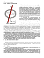
1
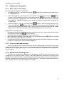
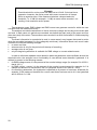
2 Operation of the analyzer 2 Operation of the analyzer 2.1 Buttons The keyboard of the analyzer consists of two buttons: ON/OFF and START/STOP . To switch-on the analyzer, press ON/OFF button. START/STOP button is used to start and stop recording. 2.2 Switching the analyzer ON/OFF The analyzer may be switched-on by pressing button . Green ON LED indicates that analyzer is switched on. Then, the analyzer performs a self-test and when an internal fault is detected, ERROR LED is lit and a long beep (3 seconds) is emitted – measurements are blocked. After the self-test, the meter begins to test if the connected mains configuration is the same as the configuration in analyzer’s memory, and when an error is detected ERROR LED flashes every 0.5 seconds. When ERROR LED flashes the analyzer still operates as normal and measurements are possible. The criteria used by the analyzer for detecting a connection error are as follows: deviation of RMS voltage exceeding ±15% of nominal value, deviation of the phase angle of the voltage fundamental component exceeding ±30 of the theoretical value with resistive load and symmetrical mains (see note below) deviation of the phase angle of the current fundamental component exceeding ±55 of the theoretical value with resistive load and symmetrical mains (see note below) network frequency deviation exceeding ±10% of the nominal frequency. Note To detect a phase error, the fundamental component of the measured sequence must be at least equal to 5% of the nominal voltage, or 1% of the nominal current. If this condition is not fulfilled, the correctness of angles is not verified. When the meter is switched on and detects full memory, MEM LED is lit – measurements are blocked, only read-out mode for current data remains active. When the meter is switched on and fails to detect the micro-SD card or detects its damage, ERROR and MEM LEDs are lit and measurements are blocked. Note The ERROR and MEM LEDs behaves the same way when a new microSD card has been inserted to the analyzer’s slot. To format the card to be usable with PQM-700 analyzer the (START/STOP) button must be pressed. Analyzer will then confirm start of formatting process with 3 beeps. All the data on the card will be erased. If the formatting finishes successfully the ERROR and MEM LEDs will switch off, and the analyzer will be ready for further operation. If the connection test was successful, after pressing mode, as programmed in the PC. To switch the analyzer OFF, keep button recording lock are active. the meter enters the recording pressed for 2 seconds, when no button or 14