1
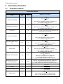
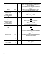
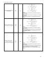
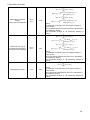
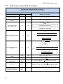
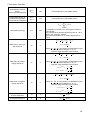
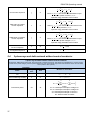
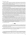
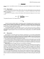
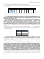
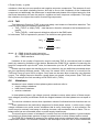
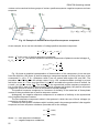
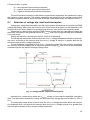
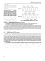
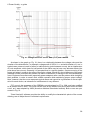
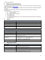
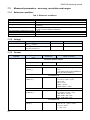
PQM-700 Operating manual 𝑆𝑁 = √𝑆 2 − (𝑈1 𝐼1 )2 where U1 and I1 are effective values of fundamental components of phase-to-neutral voltage and current. 6.4.7 Power factor True Power Factor or Power Factor (TPF or PF) is the value which takes into account also the presence of higher harmonics. For sinusoidal systems, it is equal to Displacement Power Factor (DPF), popular cos. Hence, DPF is a measure of phase shift between the fundamental voltage and current components: 𝐷𝑃𝐹 = 𝑃1 𝑈1 𝐼1 𝑐𝑜𝑠𝜑𝑈1𝐼1 = = 𝑐𝑜𝑠𝜑𝑈1𝐼1 𝑆1 𝑈1 𝐼1 The general formula for True Power Factor is: 𝑃𝐹 = 𝑃 𝑆 In case of a purely resistive load (in a one-phase system), the apparent power is equal to active power (in terms of value), and reactive power equals zero, so such load fully uses the energy potential of the source and the power factor is 1. Appearance of reactive component inevitably leads to reduction of energy transmission effectiveness – the active power is then less than apparent power, and the reactive power is increasing. In three-phase systems, the power factor reduction is also influenced by receiver unbalance (see discussion on reactive power). In such systems, correct power factor value is obtained using the effective apparent power Se that is the value defined, among others, in the IEEE 1459-2000 standard. 6.5 Harmonics Decomposition of periodic signal into harmonic components is a very popular mathematical operation based on Fourier’s theorem which says that any periodic signal can be represented as a sum of sinusoidal components with frequencies equal to multiples of basic frequency of such signal. Time-domain signal can be subjected to Fast Fourier Transform (FFT) to receive amplitudes and phases of harmonic components in the frequency domain. In a perfect situation, voltage is generated in a generator which at output gives a pure sinusoidal 50/60 Hz waveform (absence of any higher harmonics). If the receiver is a linear system, then also current in such situation is a pure sinusoidal waveform. In real systems, voltage and current waveforms can be distorted, hence in addition to the fundamental component there must be harmonics of higher orders. Why is the presence of higher harmonics in the system not desirable? One of the reasons is the skin effect which involves pushing out the electrons from the center of conductor towards the surface as the current frequency is increasing. As a result, the higher the frequency, the smaller the effective conductor cross section which is available for the electrons, which means that the conductor resistance is increasing. Consequently, the higher the current harmonics, the higher effective cabling resistance for this harmonics, and this inevitably leads to more power losses and heating. A classic example connected with this effect is related to neutral conductor in three-phase systems. In a system with little distortion, little unbalance and a balanced (or slightly unbalanced) receiver, the current in neutral conductor has the tendency of zeroing (it is much smaller that RMS phase currents). Such observation has tempted many designers to obtains savings by installing the 51