1
MODEL 6060 INSTRUCTION MANUAL
PAGE 3
NEUTRON AREA MONITOR
INSTRUMENTS
HEALTH PHYSICS
R e s e t : This is an input that resets the microprocessor. When this pin is brought high by
connecting it to the +5VDC output (pin N) the microprocessor will be reset. This is usually done with
a push-button. When the microprocessor is reset it sets the High Voltage, Discriminator, and Gain to
the stored values.
O u t p u t p u l s e:
e This is an LSTTL positive going output pulse for each discriminated event. This is
not a buffered signal, however it will drive 1 LSTTL load.
G r o u n d : Signal and power ground. This is the negative input for external power.
E x t e r n a l P o w e r : This is the positive input for external power. It can power the instrument instead
of or with the Pulse Link. The external power should be above 9 volts. The instrument can be
powered continuously by connecting external power to this input before removing the Pulse Link
connection.
+ 5 V D C O u t p u t : This is an output of 5 volts. This is the positive connection. The Ground pin is
the negative connection. It is used for the external reset switch and if needed to power external
devices.
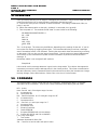
V. TEST BOX
Interrogation and adjustment of the 6060 depends on connections to the accessory socket. A
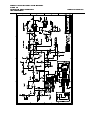
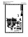
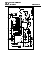
schematic of a recommended test box is shown in figure 2. The model 6120 Breakout box is available
from HPI. The user may wish to construct whatever test box or connections they may need. To
calibrate the instrument all you need is to wire pin J to L, provide a push-button switch from pin H to
N and connect an RS232 to pin F,G and L. If you want to provide test points for the various signals,
they can also be included.
Figure 2 Test Box Schematic