1
Solution 16 i
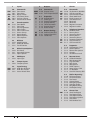
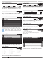
TABLE OF CONTENTS
Copyright Notice .............................................................................. 2
Trademarks ......................................................................................... 2
Notice of Liability.............................................................................. 2
Telepermit Note ................................................................................ 2
FEATURES ............................................................................ 4
OVERVIEW ........................................................................... 4
ABOUT THE PANEL .............................................................. 5
Enclosures ........................................................................................... 5
Enclosure Fixing Method ............................................................... 5
Installing The Tamper Switch ....................................................... 5
Enclosure Module Spaces.............................................................. 5
Installing Panels and Modules ..................................................... 6
Connecting Power To The Panel .................................................. 8
Connecting The Battery ................................................................. 8
A.C. mains Transformer Option.................................................... 8
Panel LED Indicators ........................................................................ 8
WIRING DIAGRAMS ............................................................ 9
EOL Resistor ColourS and Values ................................................ 9
LAN Overview ..................................................................................12
LAN Wiring ........................................................................................12
System Earthing ..............................................................................13
Terminating the LAN .....................................................................13
Terminal Descriptions ...................................................................14
Board Connectors...........................................................................14
ABOUT THE KEYPAD ......................................................... 14
Keypad Button Functions ............................................................14
Keypad Setup ...................................................................................15
Keypad Address Select .................................................................15
Status Icons / LED’s ........................................................................16
Keypad Tones ...................................................................................16
DTMF Control Functions .............................................................17
Expansion Modules .......................................................................17
Expansion Module Configuration ............................................18
PROGRAMMING OVERVIEW ............................................ 18
Entering Programming Mode ....................................................19
Exiting Programming Mode .......................................................19
Programming Structure ...............................................................19
Interpreting The Text Display .....................................................19
Programming BIT Options...........................................................19
Programming Text Locations .....................................................20
Programming Telephone Numbers .........................................20
Programming List Options ..........................................................20
Programming The Clock...............................................................21
GETTING STARTED BACK TO BASE .................................. 21
SERVICE MODE .................................................................. 21
DEFAULTING THE SYSTEM ............................................... 21
DOMESTIC TEMPLATE DEFAULTS .................................... 22
DIRECT LINK PROGRAMMING ......................................... 22
ZONE ARRAY ...................................................................... 22
BASIC REPORTING REFERENCE ....................................... 22
PROGRAMMING LOCATIONS REFERENCE TABLE .......... 24
PROGRAM LOCATIONS ..................................................... 27
Access Programming ....................................................................27
Area Programming.........................................................................28
Input Programming .......................................................................30
Zone Default Table .........................................................................31
Output Default Table .....................................................................32
Output Programming ...................................................................32
One Shot Mode ...............................................................................33
Pulsing Mode ...................................................................................33
Output Event Types .......................................................................33
Bosch Security Systems 09/07 BLCC500R FTR1.02
Copyright © 2007
Quick Start Guide
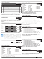
Comms Programming ..................................................................34
Device Programming ....................................................................37
System Programming ...................................................................39
TESTING THE SYSTEM....................................................... 41
SPECIFICATIONS ............................................................... 42
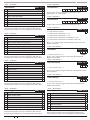
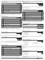
FIGURES
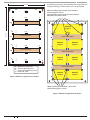
Figure 1: PCB and Mounting Clip Installation Diagram ...... 5
Figure 2: Tamper Bracket Installation ........................................ 5
Figure 3: MW700 - Small Enclosure Details ............................. 6
Figure 4: PCB Mounting Clip......................................................... 6
Figure 5: MW700 Configuration Examples .............................. 6
Figure 6: MW710 - Large Enclosure Details ............................. 7
Figure 7: MW710 Configuration Examples .............................. 7
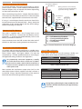
Figure 8: Internal Transformer Connection Diagram ........... 8
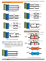
Figure 9: N/C No EOL Zone............................................................ 9
Figure 10: N/C Single EOL Zone .................................................. 9
Figure 11: N/C Split EOL Zone ...................................................... 9
Figure 12: N/C Zone With Tamper ............................................... 9
Figure 13: N/O No EOL Zone......................................................... 9
Figure 14: N/O Single EOL Zone .................................................. 9
Figure 15: N/O Split EOL Zone ..................................................... 9
Figure 16: N/O Zone With Tamper .............................................. 9
Figure 17: EOL Resistor Colour Chart......................................... 9
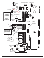
Figure 18: Solution 16i Board Layout ......................................10
Figure 19: Solution 16i Connection Diagram .......................11
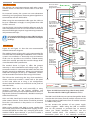
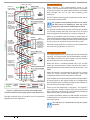
Figure 20: LAN Connection Using 2 Pair Security Cable ...12
Figure 21: LAN Connection Using Twisted Pair Cable .......13
Figure 20: Keypad Emergency Alarm Trigger’s ....................15
Figure 22: Keypad DIP Switch Address Settings ..................15
Figure 23: LCD Display Showing All ICONs ............................16
Figure 24: Text Characters Which Can Be Displayed. .........19
Figure 25: Sample Option Bit Menu Display .........................19
Figure 26: Area Text Programming Display ...........................20
Figure 27: Telephone Number Programming Display .......20
Figure 28: List Option Programming Display .......................21
Figure 29: Factory Default Display............................................22
Figure 30: Zone Array Showing Z1 to Z4...............................22
Figure 31: Zone Array Showing Z9 to Z12 ............................22
Figure 32: Text Menu Examples .................................................23
Figure 33: Character Set ...............................................................43
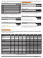
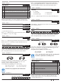
TABLES
Table 1: Expansion Options........................................................... 5
Table 2: Dialler Indicator LED ....................................................... 8
Table 3: Status Indicator LED ........................................................ 8
Table 4: Terminal Block Descriptions .......................................12
Table 5: Board Connector Descriptions ..................................12
Table 6: Keypad Emergency Alarm Trigger’s.........................13
Table 7: Keypad DIP Switch Address Settings ......................13
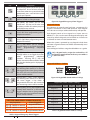
Table 8: DTMF Remote Control Functions .............................15
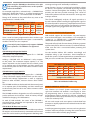
Table 9: Zone Configuration Using Expanders.....................16
Table 10: LAN Module Addressing ...........................................16
Table 11: Keys Used During Programming ............................17
Table 12: Text Keypad Character Set........................................18
Table 13: Phone Number Progamming ..................................18
Table 14: Domestic Dialing Defaults Settings ......................20
Table 15: Basic Reporting Code Reference Listing .............20
Table 16: Programming Locations and Descriptions .........24
Table 17: User Default Programming Options .....................25
Table 18: Zone Types .....................................................................28
Table 19: Zone Defaults ................................................................29
Table 20: Output Default Table ..................................................30
Table 22: Output Polarity Types .................................................31
Table 21: Output Event Types.....................................................31
E&OE
3