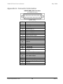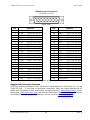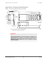
1
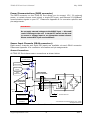
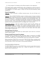
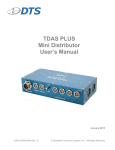
TDAS G5 iPort
User’s Manual
May 2006
Rev. 0
TDAS G5 iPort User’s Manual
May 2006
Table of Contents
DTS Support .................................................................................................... 3
Introducing the TDAS G5 iPort ........................................................................ 4
Overview of TDAS G5 iPort Features ............................................................... 4
TDAS G5 iPort Connector Panel ....................................................................... 4
Power/Communications (DB25 connector) ........................................................ 5
Sensor Input Channels (DB44 connectors) ........................................................ 5
Sensor Connections ................................................................................... 5
Sensor Input Range ................................................................................... 6
Excitation Sources ..................................................................................... 6
Electronic Identification (EID) ......................................................................... 6
Basic Care and Handling ................................................................................. 6
Shock Rating ................................................................................................ 7
Mounting Considerations............................................................................. 7
Thermal Considerations ................................................................................. 7
Power Management ........................................................................................ 7
Power Consumption....................................................................................... 8
External Power Provisions............................................................................... 8
Power-up and Power-down Procedures ............................................................. 8
Communication Features ................................................................................ 8
Communication Method.................................................................................. 9
LED Indicators .......................................................................................... 9
Using Multiple TDAS G5 iPorts ..................................................................... 9
Appendix A: Connector Information ............................................................. 10
Suggested Connector Sources........................................................................11
Appendix B: Mechanical Specifications......................................................... 12
[email protected]
ii
Rev. 0
TDAS G5 iPort User’s Manual
May 2006
DTS Support
TDAS systems are designed to be reliable and simple to operate. Should you need
assistance, DTS has support engineers worldwide with extensive product knowledge
and crash test experience to help via telephone, e-mail or on-site visits.
The best way to contact a DTS support engineer is to e-mail [email protected].
Your e-mail is immediately forwarded to all DTS support engineers worldwide and is
typically the fastest way to get a response, particularly if you need assistance outside
of normal business hours.
For assistance by telephone, please go to
http://www.dtsweb.com/support.html to find the phone number appropriate for your
region of the world.
[email protected]
3
Rev. 0
TDAS G5 iPort User’s Manual
May 2006
Introducing the TDAS G5 iPort
The TDAS G5 iPort allows for easy installation of a TDAS G5 Data Acquisition System
(DAS) into a crashworthy enclosure for dynamic testing applications. Power, Ethernet
communication and event signals are easily accessible via the DB25F connector.
Sensors are easily connected via four DB44F connectors. A TDAS G5 DAS can be
moved easily from an in-dummy application to a TDAS G5 iPort for maximum flexibility
of data acquisition resources. TDAS G5 iPorts may be interconnected via a TDAS G5
Distributor, TDAS PLUS Mini Distributor or TDAS PLUS Distributor to create higher
channel-count systems.
This manual discusses the features and options available with the TDAS G5 iPort. To
identify the specific hardware included with your system, please see your packing list.
Overview of TDAS G5 iPort Features
•
•
•
•
•
•
•
Built and tested for 100+ G dynamic testing environments.
32 sensor input channels.
5 volt excitation sources.
Ethernet 10/100BaseT communications.
Contact-closure event input.
Electronic identification (EID) support.
Integral mounting holes.
Please see the DTS web site (www.dtsweb.com) for the latest hardware specifications.
TDAS G5 iPort Connector Panel
[email protected]
4
Rev. 0
TDAS G5 iPort User’s Manual
May 2006
Power/Communications (DB25 connector)
The DB25 connector on the TDAS G5 iPort allows you to connect 15 V, 2 A external
power, a contact-closure event signal, a single EID input, and Ethernet 10/100BaseT
communication signals to your PC. Please see Appendix A for connector specifics and
pin assignments.
WARNING:
Do not apply external voltages to the EVENT input — this could
result in damage to the unit. A simple FET switch can be used
to convert a voltage input to an appropriate contact closure.
Please contact DTS if you need assistance.
Sensor Input Channels (DB44 connectors)
Eight sensor channels and eight EID inputs are available via each DB44 connector.
Please see Appendix A for connector information and pin assignments.
Sensor Connections
All TDAS G5 iPorts have sensor connections as shown below.
Excitation
5 volts 20 mA
Excitation
Check ADC
Shunt Check
Driver
Gain
Calibration
TDAS G5 DAS
Sensor Connector
+Ex
+Sig
ID/digital
Shield
-Sig
-Ex
+
Differential
Instrumentation
Amplifier
-
+Ex
Dallas ID
guide pin
2.5 V
Ref
R
R
+Sig
R
R
-Sig
-Ex
+5 V
Contact Closure
Digital Inputs
Dallas ID
Interface
©Diversified Technical Systems, Inc., 2004
All Rights Reserved
Sensor Connections
[email protected]
5
Rev. 0
TDAS G5 iPort User’s Manual
May 2006
Sensor Input Range
The nominal sensor input range is ±2.5 volts (differential) at a gain of 1. The rated
common-mode voltage range is 0.3 to 4.7 volts.
Excitation Sources
All excitation sources are individually regulated and limited
to ensure reliable
operation even with shorted cables. The standard excitation voltage is 5.0 volts.
Excitation sources are not turned on until the software initializes the system during the
Real-Time or Collect Data modes.
Electronic Identification (EID)
The TDAS G5 iPort supports communication with silicon serial number devices
manufactured by Dallas Semiconductor/Maxim Integrated Products. When an ID chip
such as the DS2401 is connected to the proper pins on the DB25 or DB44 connectors,
the TDAS Control software can automatically read these devices and correlate the
serial number to channel set-up information stored in a Sensor Information File (SIF).
When wiring any device for EID, proper polarity must be observed and cable length
should not exceed 9.14 meters (30 feet).
Basic Care and Handling
The TDAS G5 iPort is designed to be reliable and simple to operate. Though resistant
to many environmental conditions, care should be taken not to subject the unit to
harsh chemicals, submerge it in water, or drop it onto any hard surface.
WARNING:
Electronic equipment dropped from desk height onto a solid
floor may experience as much as 10,000 Gs. Under these
conditions, damage to the exterior and/or interior of the unit is
likely.
When transporting the unit, treat it as you might a laptop computer and you should
have no problems. If a TDAS G5 DAS is not installed in the unit, we strongly
recommend reattaching the clear plastic cap to cover the opening and protect the
connector interface on the unit. When not in use or if shipping is required, we suggest
that you always place the unit in the padded carrying case originally provided with
your system.
[email protected]
6
Rev. 0
TDAS G5 iPort User’s Manual
May 2006
WARNING:
The 216-position, gold-plated, interface connector on the TDAS
G5 iPort should be treated with great care. It is through this
interface that all signals enter and exit the DAS. Any debris,
solvents, or oil (even from fingers) can compromise the
integrity of the connections/signals.
If you feel the interface connector on your TDAS G5 iPort has become contaminated,
please contact DTS support before attempting any cleaning procedure.
The TDAS G5 iPort is not user-serviceable and should be returned to the factory for
service or repair.
Shock Rating
All crashworthy TDAS G5 equipment is rated for and fully tested to 100+ Gs, 12 msec
duration, in all axes and can be mounted directly on a vehicle, sled, wall or other
dynamic testing device.
Mounting Considerations
Mounting methods and mounting bolt selection should be carefully calculated so as to
withstand expected shock loading and facilitate proper grounding. (See Appendix B for
the unit’s mechanical specifications.) Careful consideration should be also given to
connecting the D-sub cable harnesses with the TDAS G5 iPort and their movement
within a dynamic testing environment. Movement of cable harnesses should be
appropriately restricted to ensure testing success.
Thermal Considerations
TDAS G5 systems use extensive power management to minimize heat generation.
Since the system draws the most power when armed, running the calibrations and
arming as late as possible will minimize self-heating.
It is extremely unlikely that excessive heat will ever be an issue in real-world testing
applications using TDAS G5 systems. However, if high ambient temperatures, exposure to other heat sources, or severely restricted airflow will cause case temperatures
in excess of 50°C (too hot to touch comfortably), the airflow created by a small fan will
increase heat transfer by a factor of 3 to 5. Additionally, always shield the units from
exposure to direct sunlight.
Power Management
A good power source is of paramount importance.
powered from either:
Each TDAS G5 iPort should be
1) A high-quality 15-volt power supply with a current rating of at least 2 amps (this
would include the TDAS PLUS Distributor and TDAS PLUS Mini Distributor);
[email protected]
7
Rev. 0
TDAS G5 iPort User’s Manual
May 2006
2) A fully-charged 12-volt battery with sufficient capacity for the application.
DTS-supplied power supplies and distribution units are designed to meet all criteria for
proper charging and operation. If you need help determining which set-up is best for
your application or if a power supply or charger will meet the power demands, please
contact DTS.
Power Consumption
Power off:
1/2 mA.
When connected to sufficient external power, the unit will draw up to
Power on: When a TDAS G5 DAS/iPort system is initially powered, all sensor excitation
sources, signal conditioning electronics, filter circuits and analog-to-digital converters
are in a shutdown state. The processor and support circuitry are always powered. The
processor will remain in a reduced power state when not performing tasks. When the
user runs a test set-up, the software automatically energizes the excitation sources
and other circuits. The current draw will increase to as much as 1.4 amps when the
system is fully armed and powering 350 ohm bridges with 5 volt excitation.
During data collection: Once the system has been armed for data collection, all
circuits remain in a full power state until the system finishes storing data. After the
data collection routine is complete, the system de-energizes several circuits to
minimize power consumption. It takes a maximum of 125 seconds after the end of the
data storage window for the system to return to the idle state, which then allows
communication and download.
External Power Provisions
The TDAS G5 iPort does not contain any internal power source but has a connector
input for primary power.
Power-up and Power-down Procedures
The TDAS G5 iPort is powered up when the proper signal is connected at the DB25
connector. The absence of the same signal will turn off the unit. Power-up of a TDAS
G5 DAS/iPort system takes ~20 seconds after which time communication is enabled.
Before restarting a TDAS G5 iPort, wait until all TDAS G5 DAS LEDs go completely dark
and then wait 10 seconds more to be sure. An incomplete power-down/power-up
cycle can result in errors, so be certain to follow proper procedures.
Communication Features
The DB25 PWR/COM connector on the TDAS G5 iPort connector panel allows access to
all communication features and status lines. (Please see Appendix A for connector
specifics and pin assignments.)
[email protected]
8
Rev. 0
TDAS G5 iPort User’s Manual
May 2006
Communication Method
The TDAS G5 iPort supports the industry-standard Ethernet 10/100BaseT
communication method. The unit itself does not contain an IP-addressable controller;
communication is only possible when the unit contains a TDAS G5 DAS.
Communication is enabled after the power-up sequence has completed (~20 seconds).
LED Indicators
As a standalone device, the TDAS G5 iPort does not contain any LED indicators.
Ongoing status information is provided via the TDAS G5 DAS (five red/yellow/green
LEDs). Please see Appendix A in the TDAS G5 DAS User’s Manual for a detailed
description of the LED indicators.
COM:
CAL:
PWR:
ARM:
STAT:
Provides
Provides
Provides
Provides
Provides
status on communications between the PC and DAS.
calibration status.
status on power to the DAS.
arm, start record, and event status.
general status.
WARNING:
Do not perform any critical tests when the PWR LED indicator
on the TDAS G5 DAS is yellow (power low) or red (power
critical). There is no back-up battery within the TDAS G5 iPort.
Using Multiple TDAS G5 iPorts
To create higher channel-count systems, TDAS G5 iPorts may be interconnected via a
TDAS G5 Distributor, TDAS PLUS Mini Distributor or TDAS PLUS Distributor. All
Distributors support communications, with the TDAS PLUS Mini Distributor and TDAS
PLUS Distributor also supporting power requirements for the TDAS G5 iPort.
[email protected]
9
Rev. 0
TDAS G5 iPort User’s Manual
May 2006
Appendix A: Connector Information
DB25F PWR/COM Connector
(172-025-212-011)
(panel view)
Pin
1
2
3
4
5
6
7
8
9
10
11
12
13
14
15
16
17
18
19
20
21
22
23
24
25
[email protected]
Function
Ground
+15 VDC
+15 VDC
Ethernet Rx (+)
Ethernet Rx (-)
Ethernet Tx (+)
Ethernet Tx (-)
Record status output
- Event, contact closure to pin 10
+ Event, contact closure to pin 9
+ ID
Ground
Ground
- ID/Ground
- ID/Ground
- ID/Ground
Start record (contact closure to
pin 18)
Start record (5 V = start)
Arm status input
Arm status output
Record status input
Ground
Power on signal (to ground)
Ground
Ground
10
Rev. 0
TDAS G5 iPort User’s Manual
May 2006
DB44F sensor Connectors
(180-044-212-011)
(panel view)
Pin
1
2
3
4
5
6
7
8
9
10
11
12
13
14
15
16
17
18
19
20
21
22
Function
Pin
Function
- Ex
(Ch 8, 16, 24, 32)
23
+ Ex
(Ch 5, 13,
+ Sig
(Ch 8, 16, 24, 32)
24
+ Sig
(Ch 4, 12,
- Sig
(Ch 7, 15, 23, 31)
25
- Sig
(Ch 3, 11,
+ Ex
(Ch 7, 15, 23, 31)
26
+ Ex
(Ch 3, 11,
- Sig
(Ch 6, 14, 22, 30)
27
- Sig
(Ch 2, 10,
+ Ex
(Ch 6, 14, 22, 30)
28
+ Ex
(Ch 2, 10,
+ Sig
(Ch 5, 13, 21, 29)
29
- Sig
(Ch 1, 9,
- Sig
(Ch 4, 12, 20, 28)
30
+ Ex
(Ch 1, 9,
+ Ex
(Ch 4, 12, 20, 28)
31
- ID/Ground
+ Sig
(Ch 3, 11, 19, 27)
32
+ ID
(Ch 8, 16,
- Ex
(Ch 2, 10, 18, 26)
33
+ ID
(Ch 7, 15,
+ Sig
(Ch 2, 10, 18, 26)
34
- Ex
(Ch 7, 15,
- Ex
(Ch 1, 9, 17, 25)
35
+ ID
(Ch 6, 14,
+ Sig
(Ch 1, 9, 17, 25)
36
+ ID
(Ch 5, 13,
- ID/Ground
37
- Ex
(Ch 5, 13,
- ID/Ground
38
+ ID
(Ch 4, 12,
- Sig
(Ch 8, 16, 24, 32)
39
- Ex
(Ch 4, 12,
+ Ex
(Ch 8, 16, 24, 32)
40
+ ID
(Ch 3, 11,
+ Sig
(Ch 7, 15, 23, 31)
41
- Ex
(Ch 3, 11,
- Ex
(Ch 6, 14, 22, 30)
42
+ ID
(Ch 2, 10,
+ Sig
(Ch 6, 14, 22, 30)
43
+ ID
(Ch 1, 9,
- Sig
(Ch 5, 13, 21, 29)
44
- ID/Ground
Channels 1-8, 9-16, 17-24, 25-32 are assigned per connector, respectively.
21,
20,
19,
19,
18,
18,
17,
17,
29)
28)
27)
27)
26)
26)
25)
25)
24,
23,
23,
22,
21,
21,
20,
20,
19,
19,
18,
17,
32)
31)
31)
30)
29)
29)
28)
28)
27)
27)
26)
25)
Suggested Connector Sources
DTS uses industry-standard D-sub connectors manufactured by NorComp Inc. on the
TDAS G5 iPort. If you need to purchase connectors, there are many distributors for
these and compatible D-sub connectors including Digi-Key (www.digikey.com), Force
Electronics (www.force-elec.com) and Mouser Electronics (www.mouser.com). Contact
information for NorComp Inc. distributors can be found at www.norcomp.net.
[email protected]
11
Rev. 0
TDAS G5 iPort User’s Manual
May 2006
Appendix B: Mechanical Specifications
Weight: 912 grams (TDAS G5 DAS not included)
2.37 inches/
60.19 mm
0.394 inches/
10 mm
·
2 inches/
50.8 mm
2.6 inches/
66.04 mm
·
8.945 inches/227.2 mm
0.2 inches/5.08 mm
2.2 inches/55.88 mm
2.26 inches/
57.4 mm
·
·
M5 screws (x2); length ≥30 mm
M7 x 0.7 pitch
screws (x2)
·
0.875 inches/
22.23 mm
2.5 inches/
63.5 mm
M5 x 0.8 pitch
screws (x2);
should penetrate
unit 8 mm
Torque specification for screws (4) fastening DAS
to unit: 1.6 to 18 Nm or 14 to 16 in-lb
WARNING:
The torque specification is critical for proper connection of the
TDAS G5 DAS (1.6 to 1.8 Nm or 14 to 16 in-lb). If the bolts are
tightened too little, good contact will not be made; if they are
tightened too much, damage may result. Please use a torque
wrench if possible.
[email protected]
12
Rev. 0