1
PowerFlex 700 AC Drives, Frames 0...6 3
ATTENTION: Only qualified personnel familiar with adjustable frequency AC drives and associated machinery should plan or implement the installation, start-up and subsequent maintenance of the system. Failure to comply may
result in personal injury and/or equipment damage.
ATTENTION: An incorrectly applied or installed drive can result in component damage or a reduction in product life. Wiring or application errors such as under sizing the motor, incorrect or inadequate AC supply, or excessive
surrounding air temperatures may result in malfunction of the system.
ATTENTION: Drive must not be installed in an area where the ambient atmosphere contains volatile or corrosive gas, vapors or dust. If the drive is not going to be installed for a period of time, it must be stored in an area where it
will not be exposed to a corrosive atmosphere.
Operating Temperatures
PowerFlex 700 drives (frames 0...6) are designed to operate at 0…40 ° C (32…104 °F) ambient. To operate the drive in installations between 41…50 ° C (106…122 °F), see the information below and refer to pages 4 through 8 for exceptions.
Acceptable Surrounding Air Temperature & Required Actions
Enclosure Rating
IP20, NEMA/UL Type 1 (with Top Label)
(1)
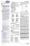
Minimum Mounting Clearances
Temperature Range
Drive
0…40 ° C (32...104 °F)
Frames 0…4,
All Ratings
Frames 5…6,
Most Ratings (2)
0…50 ° C (32...122 °F)
0…50 ° C (32...122 °F)
IP20, NEMA/UL Type Open
(Top Label Removed) (1)
0…45 ° C (32...113 °F)
0…50 ° C (32...122 °F)
IP00, NEMA/UL Type Open
(Top Label & Vent Plate Removed)
Flange Mount
Front - IP00, NEMA/UL Type Open
Stand-alone/Wall Mount-IP54, NEMA/UL 12
(2)
(3)
101.6 mm
(4.0 in.)
20BC072 Only (3)
0…55 ° C (32...131 °F)
Front (Inside Encl.)
0…40 ° C (32...104 °F)
Back (External)
0…40 ° C (32...104 °F)
Back/Heat Sink-IP54, NEMA/UL Type 12
(1)
Most Ratings (2)
20BC072 Only
Specified vertical clearance requirements are intended to be from the drive to the closest object that can
restrict airflow through the drive heat sink and chassis. The drive must be mounted in a vertical orientation as
shown, and must make full contact with the mounting surface. Do not use standoffs or spacers. In addition,
inlet air temperature must not exceed the product specification.
Frames 5…6
101.6 mm
(4.0 in.)
101.6 mm
(4.0 in.)
PWR
PWR
STS
STS
PORT
PORT
MOD
MOD
NET A
NET A
NET B
NET B
No Adhesive Label
(see table, left)
PORT
MOD
NET A
NET B
With Adhesive Label
(see table, left)
101.6 mm
(4.0 in.)
PWR
PWR
STS
STS
50.8 mm
(2.0 in.)
PORT
MOD
NET A
NET B
Frames 5…6
Removing the adhesive top label from the drive changes the NEMA/UL enclosure rating from Type 1 to Open. Frames 5 and 6 do
not have a top label.
Refer to pages 4 through 8 for exceptions.
To remove vent plate (refer to User Manual for location), lift top edge of plate from the chassis. Rotate the plate out from the back
plate.
101.6 mm
(4.0 in.)
101.6 mm
(4.0 in.)
101.6 mm
(4.0 in.)
101.6 mm
(4.0 in.)
Drive Weights
Frame
Weight (1)
kg (lb)
Frame
Weight (1)
kg (lb)
NEMA/UL Type 12
(400…690V drives only)
Weight (1)
kg (lb)
0
1
2
3
5.22 (11.5)
7.03 (15.5)
12.52 (27.6)
18.55 (40.9)
4
5
6
24.49 (54.0)
37.19 (82.0)
71.44 (157.5)
Frame 5 NEMA/UL Type 12 Standalone
Frame 5 NEMA/UL Type 12 Flange Mount
Frame 6 NEMA/UL Type 12 Standalone
Frame 6 NEMA/UL Type 12 Flange Mount
102.51 (226.0)
61.69 (136.0)
176.90 (390)
99.79 (220.0)
(1)
Weights include HIM and Standard I/O.
Leakage Current
• PowerFlex 700 drives produce leakage current in the protective earthing conductor which exceeds 3.5 mA AC and/or 10 mA DC. The minimum size of the protective earthing (grounding) conductor used in the application must comply with
local safety regulations for high protective earthing conductor current equipment.
• PowerFlex 700 drives produce DC current in the protective earthing conductor and may reduce the ability of a residual current device (RCD) or residual current monitor (RCM) of type A or AC to provide protection for the drive and other
equipment in the installation.
Motor Overload Protection - PowerFlex 700 Drives with Standard Control
PowerFlex 700 drives with standard control, identified by an N, A, or B in position 15 of the catalog number, only provide Class 10 motor overload protection according to NEC article 430. They do not provide speed sensitive overload protection,
thermal memory retention and motor over-temperature sensing according to NEC article 430.126 (A) (2). If such protection is needed in the end-use product, it must be provided by additional means.
Motor Overload Protection - PowerFlex 700 Drives with Vector Control
PowerFlex 700 drives with vector control, identified by a C or D in position 15 of the catalog number, provide class 10 motor overload protection according to NEC article 430 and motor over-temperature protection according to NEC article 430.126
(A) (2). UL 508C File E59272.
Short Circuit Current Rating
Maximum Short Circuit Rating:
200,000 Amps symmetrical.
Branch Circuit Short Circuit Protection
Integral solid state short circuit protection does not provide branch circuit protection. Branch circuit protection must be provided in accordance with the National Electric Code (NEC) and any additional local codes, or the equivalent. The tables on
the following pages provide drive ratings (including continuous, 1 minute and 3 second) and recommended AC line input fuse and circuit breaker information. Both types of short circuit protection are acceptable for UL and IEC requirements. Sizes
listed are the recommended sizes based on 40 °C (104 °F) and the U.S. N.E.C. Other country, state or local codes can require different ratings.
Fuse and Circuit Breaker Ratings
The tables on the following pages provide recommended AC line input fuse and circuit breaker information. See Fusing and Circuit Breakers below for UL and IEC requirements. Sizes listed are the recommended sizes based on 40 °C (104 °F) and
the U.S. NEC. Other country, state, or local codes can require different ratings. Tables with DC link fuse recommendations for DC input drives are also provided.
Fusing
The recommended fuse types are listed below. If available current ratings do not match those listed in the tables provided, choose the next higher fuse rating.
• IEC – BS88 (British Standard) Parts 1 & 2, EN60269-1, Parts 1 & 21, type gG or equivalent should be used.
• UL - UL Class CC, T, RK1 or J should be used.
1
Typical designations include, but may not be limited to the following; Parts 1 & 2: AC, AD, BC, BD, CD, DD, ED, EFS, EF, FF, FG, GF, GG, GH.
Rockwell Automation Publication 20B-PC001C-EN-P - July 2013