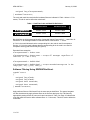
1
APN-040 Rev 1
January 21, 2008
Application Note on the Use of a Controller Area
Network (CAN) and Application Program Interface (API)
This application note offers definitions of NovAtel’s CAN and API features. It also explains how to
utilize the API properly for transmitting or receiving one of two types of CAN frames.
References to footnote numbers that appear in square brackets are at the back of this application
note on Page 13.
The CAN Protocol
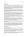
The CAN protocol is a means for devices (nodes) to communicate with one another efficiently
and robustly. Originally designed for automotive applications, it uses robust physical signaling
methods to ensure low error rates in the presence of ground loops, voltage mismatches, and
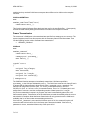
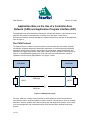
otherwise poor signal environments. CAN nodes, known as ECU’s (Electronic Control Units) coexist on a 2-wire differential signaling bus. Each end of the bus terminates with a 120-ohm
impedance to ensure proper signal balance, see Figure 1 below.
CAN Node
CAN Node
CAN High
120 Ω
120 Ω
CAN Low
Figure 1 CAN Physical Layers
The term “CAN bus” is widely used to describe an entire system of interconnected devices.
CAN permits nodes of unequal capability to share a network. This has proven to be an essential
attribute in vehicular systems where low-complexity/low-rate temperature sensors must co-exist
on a bus with high-rate, high complexity sensors such as wheel slip or steering wheel angle
sensors.
1 of 13
APN-040 Rev 1
January 21, 2008
Background
The CAN protocol has evolved out of network definitions pioneered by Robert Bosch GmbH and
first introduced in 1996 as CAN 1.0 with an 11-bit identifier (standard message frame). [1]
CAN is a series of standards. The ISO 11898-1 standard, defines the physical layer (hardware),
data link layer (message formatting) of the CAN standard and extended messages. ISO 11898-2
defines high-speed operations between 125 kbps to 1000 kbps. In practice, the standards are
identical in physical signaling and framing. They differ in the higher levels of communication,
including networking and application layers.
As an example, J1939 (defined by the SAE – Society of Automotive Engineers) and ISO 11783
(defined by the ISO – International Standards Organization) refer to a series of standards
specifically targeting interoperability in the agricultural industry, including operation with a virtual
terminal. ISOBUS is an agricultural industry initiative to define minimum levels of interoperability
against the ISO 11783 standard.
As an example of using CAN for higher-level applications, some agricultural auto-steering
applications make extensive use of CAN. The guidance application communicates with the tractor
control functions through the 11783 protocol and CAN-capable steering valves. As guidance
functions become more sophisticated, higher levels of ISO 11783 define the operation that
implements and controls engine and hydraulic systems to permit automatic turning.
NEMA 2000 is a CAN standard supported by the National Marine Electronics Association and
designed to support networking in marine applications. It functions over a longer physical
distance, and supports more physical nodes than ISO 11783. The precise differences are outside
the scope of this document.
The challenge for a systems integrator is to ensure that the CAN bus protocol can interpret
appropriate messages from a vehicle. The CAN standards permit manufacturer-defined
messages, and integrators will find that some knowledge of these manufacturer-defined
messages is necessary for advanced CAN control. However, key positioning messages related to
position, velocity, and time are defined publicly in the standards.
A number of CAN protocol stacks are available as third-party applications. Higher-level software
protocols such as CANOpen [2] and DeviceNet [3] are available for development from third party
software companies.
The NovAtel API [4] developer selects the appropriate protocol stack, be it for agriculture,
automotive or aerospace applications. The developer can then gain access to the computing
resources and CAN supporting hardware on a NovAtel OEM positioning engine. NovAtel’s
OEMV-3 GNSS receiver includes a full CAN 2.0B processor, as well as the physical-level
transceivers for differential signaling. The OEMV-1 and OEMV-2 GNSS receivers include the full
CAN 2.0 processor but require transceivers external to the board.
The CAN Frame
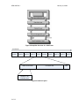
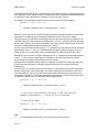
The OEM CAN API operates at the level of the CAN frame. Figure 2 on Page 3 shows a
simplified overview of the CAN frame.
CAN frames are defined as either standard or extended. Each frame is marked by a unique CAN
protocol header, see Figure 3 on Page 3, designating the number of bits used to encode the
frame ID field. The standard frame type has an 11-bit ‘frame ID’ field in the CAN protocol header
while the extended frame type has a 29-bit ID field permitting a much larger number of CAN
message types. The API has support for both frame types.
The configuration of CAN frame filters and the transmission of CAN frames depends on the frame
type selected for use in the target CAN network. This application note explains how to utilize the
API properly for transmitting or receiving CAN frames of either type.
2 of 13
APN-040 Rev 1
January 21, 2008
Figure 2 Simplified Overview of a CAN Frame
Transmission
Frame 1
Frame 2
Frame 3
Frame 4
CAN Protocol Header
Frame 5
Frame 6
0 to 8 bytes data
Identifier
Standard: 11-bit
Extended: 29-bit
Figure 3 Protocol Layers
3 of 13
Frame 7
Frame 8
Frame 9
Frame 10
CRC
APN-040 Rev 1
January 21, 2008
NovAtel’s CAN Interface
Features
•
OEMV-3 supports two independently configurable CAN ports (only one CAN port on the
OEMV-2 card)
° The CAN 2.0B processor in the NovAtel receivers supports multiple bus rates
from 10 kbps to 1000 kbps. It is important to note that while the CAN processor
supports the full CAN 2.0B processor specification, the effective bus rate,
supported by J1939, is up to 125 kb/s, while ISO 11783 supports up to 500 kb/s.
° The CAN 2.0B processor in the NovAtel receivers supports the definition of
message and frame masks or filters. Since each node in the CAN bus can listen
to all other nodes, it is necessary to filter bus traffic for messages destined only
for the CAN application in the receiver. The CAN 2.0B processor supports:
•
up to 31 unique filters for extended frames (16 “hard” and 15 “soft” filters)
•
up to 16 unique filters for standard frames (hard filters only)
See also the Special Notes on Filtering section, starting on Page 10, for more information on hard
and soft filters.
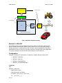
Physical Interface
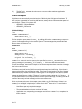
The NovAtel OEM positioning engine provides one or two CAN ports, depending on the model.
OEMV-1, OEMV-1G and OEMV-2 ports consist of pairs of TTL-level signals (transmit and
receive) to which the system integrator must connect the appropriate bus driver hardware as
shown in Figure 4 on Page 5. The OEMV-3 has two CAN transceivers, CAN1 and CAN2, but
proper off-board bus termination is still required. Refer to the Technical Specifications appendix in
the OEMV Family Installation and Operation User Manual for OEMV card pin-outs. [5]
The choice of driver depends on the physical layer implementation of the target CAN bus
network. A common physical layer standard is ISO 11898 [6] that describes a 2-wire differential
bus configuration. Bus drivers are available from many different manufacturers.
Software (User) Interface
NovAtel provides an optional OEM Application Program Interface (API) to allow customers to
write software to connect the NovAtel OEM positioning engine to their CAN network.
Configuration for this option is through NovAtel’s model definitions for the cards. If enabled, the
API provides a collection of functions that enable the system integrator to send and receive CAN
frames. The system integrator is required to implement any higher-level protocols and
functionality (DeviceNet, and so on) on top of the API.
The CAN portion of the API groups interface functions into these three categories:
1. Configuration
2. Transmission
3. Reception
4 of 13
APN-040 Rev 1
January 21, 2008
User Application Software
Customer Supplied
s have
-3 card
r
OEMV transceive
wn
their o
OEM API Software
NovAtel Supplied
CPU
CAN
Protocol
Hardware
CAN Bus
Transceiver
Hardware
CAN Bus
NovAtel OEM Positioning Engine
Figure 4 NovAtel’s CAN Bus Interface
NovAtel’s CAN API
The following sections provide a detailed API function reference. Refer also to the API User
Manual, available from NovAtel Customer Service if the receiver is an API-capable model. It
contains information on working with the API to be able to develop applications for NovAtel’s
OEM4/OEMV families of receivers. It provides information on building and loading applications.
The system integrator can find other API function details in the API header file.
Configuration
Configure a CAN port for transmission or reception by using the following function calls:
•
OEM4API_CANXOpen
•
OEM4API_CANClose
•
OEM4API_CANAddSWFilter
•
OEM4API_CANClearAllSWFilters
CANXOpen
BOOL
OEM4API_CANXOpen(
CANPortEnum ePort_,
CANBitRateEnum eBitRate_,
HardCANFilterStruct* pstFilter_,
int
5 of 13
iPriority_ );
APN-040 Rev 1
typedef enum
{
CANBITRATE_10K
CANBITRATE_20K
CANBITRATE_50K
CANBITRATE_100K
CANBITRATE_125K
CANBITRATE_250K
CANBITRATE_500K
CANBITRATE_800K
CANBITRATE_1M
} CANBitRateEnum;
January 21, 2008
=
=
=
=
=
=
=
=
=
0,
1,
2,
3,
4,
5,
6,
7,
8
typedef enum
{
CANPORT1 = 1,
CANPORT2 = 2
} CANPortEnum;
typedef struct
{
BOOL bInUse;
BOOL bExtended;
unsigned long ulAcceptanceCode;
unsigned long ulAcceptanceMask;
} HardCANFilterStruct;
A CAN port, ePort_, on the NovAtel OEM positioning engine is opened and initialized to the
specified rate eBitRate_. In addition, up to 16 CAN ‘hard’ frame filters, pstFilter_, are
initialized in the CAN protocol hardware. At least one filter must be enabled (bEnabled = TRUE)
for any CAN frames (data) to be received into the application.
Hard filters exist within the CAN protocol hardware. These filters do not take any CPU cycles to
function and are thus preferred over ‘soft’ filters (see the CANAddSWFilter section below for more
details).
Do not use the iPriority_ field on OEMV platforms but leave as zero (0).
CANClose
BOOL
OEM4API_CANClose(
CANPortEnum ePort_ );
This command disables the specified port, ePort_, and no longer communicates with the CAN
bus. Additionally, it removes power to the CAN protocol hardware. To open the port again, the
command CANXOPEN must be re-asserted.
CANAddSWFilter
BOOL
OEM4API_CANAddSWFilter(
CANPortEnum ePort_,
SWCANFilterStruct* pstFilter_ );
The software filters have two purposes: to filter CAN frames based on the data portion of the
frame, or to implement more than the 16 filters provided by the hard filter mechanism. Call this
function up to 15 times per ePort_ to add a maximum of 15 soft filters referenced by
pstFilter_. If the system integrator adds at least one soft filter, the soft filters are considered
6 of 13
APN-040 Rev 1
January 21, 2008
enabled and any received CAN frames must pass the soft filters to be visible to the reception
functions.
CANClearAllSWFilters
BOOL
OEM4API_CANClearAllSWFilters(
CANPortEnum ePort_ );
This function clears all software filters that have been set for the specified ePort_. Consequently,
all received CAN frames passing the hard filters are visible to the reception functions.
Frame Transmission
The contents of a CAN frame to be transmitted are specified in a CANMsgStruct structure. The
system integrator must fill out this structure with the necessary frame ID and frame data. Then
use the following function calls to facilitate frame transmission:
•
OEM4API_CANSend
CANSend
BOOL
OEM4API_CANSend(
CANPortEnum ePort_,
CANMsgStruct* pstCANMsg_,
BOOL bBlock_ );
typedef struct
{
unsigned long ulMsgID;
BOOL bExtended;
unsigned int iLength;
unsigned char aucData[8];
} CANMsgStruct;
The CANSend function attempts to immediately transmit the CAN frame specified in
pstCANMsg_ to the CAN port indicated by ePort_. The CAN frame must have its frame ID set in
ulMsgID and the frame typeset in bExtended (TRUE = extended, FALSE = standard). The
frame ID can range from 0 to 2047 (0x0 to 0x7FF) for standard frames or from 0 to
536,870,911 (0x0 to 0x1FFF FFFF) for extended frames. From 0 to 7, fill data bytes in and
assign them to aucData, and the corresponding number of data bytes set in iLength.
If a previous transmission request is in progress, the frame is automatically placed into a 32frame transmit queue. Transmission of the queued frame proceeds immediately after the current
transmission is complete. Note that frame transmission can only proceed once the CAN bus is
available, that is, no other nodes are transmitting at that time.
If the bBlock_ parameter is TRUE and the 32-frame queue is full, the CANSend function call
causes the task to block until a slot in the frame queue becomes available. If the bBlock_
parameter is FALSE, transmitted frames drop if the queue is full.
7 of 13
APN-040 Rev 1
January 21, 2008
Practically speaking, the bBlock_ parameter has no effect and the chance of dropping a frame is
zero unless 33 or more frames transmit in a single burst. Define a frame burst as a repeating loop
of CANSend function calls without an OEM4API_TaskSleep call in the loop.
For example, avoid the following frame burst would result in the 33rd frame dropping.
For(int i = 0; i < 33; i++)
{
OEM4API_CANSend(CAN1, pstMyCANFrame, FALSE);
}
Without a TaskSleep the CPU can fill the transmit queue much faster than can be read out and
transmitted on a CAN bus by the CAN protocol hardware even at a bus rate of 1 Mbps.
The sleep interval for TaskSleep is chosen based on bus rate, frame size and bus conditions. An
extended CAN frame, with the maximum 8 data bytes is 127 bits.[7] A collision-free bus minimizes
the inter-frame space to just 3 “frame intermission” bits, which can be considered part of the CAN
frame for this discussion (total frame size becomes 130 bits).
At a bus rate of 1000 kbps, the bit period is 1 μs. Transmitting a single frame on this bus will take
approximately (130 x 1 = 130 μs). A TaskSleep interval of approximately (32 frames x 130 μs),
rounded up to 5 ms, would suffice to allow a 32 frame burst to empty out the transmit queue.
Alternatively, at a bus rate of 125 kbps, the bit period is 8 μs. A single frame takes approximately
(130 x 8 ≈ 1 ms) to transmit and therefore a TaskSleep of 32 frames (at least 32 ms; ideally
more) is required to empty the transmit queue at this bus rate.
Note that these calculations assume ideal bus conditions (no collisions or errors) and serve only
to guide the system integrator in developing applications for their own particular CAN bus
requirements.
A frame burst of 32 or fewer frames at a time results in no lost frames if the TaskSleep interval
between frame bursts is sufficiently large. The system integrator must choose the TaskSleep
interval (perhaps 20 ms) to ensure all frames transmit after a burst taking into account the bus
rate and bus congestion. The example code below shows how two successive frame bursts with
an interleaved TaskSleep can succeed without dropping frames.
For(int i = 0; i < 32; i++)
{
OEM4API_CANSend(CAN1, pstMyCANFrame, FALSE);
}
// wait until previous burst has made it out onto the bus
OEM4API_TaskSleep(20); // sleep for 20 milliseconds
// burst more frames
For(int i = 0; i < 32; i++)
{
OEM4API_CANSend(CAN1, pstMyCANFrame, FALSE);
}
Tips
1)
8 of 13
If it is necessary to burst frames, do not exceed 32 frames per burst.
APN-040 Rev 1
January 21, 2008
The bBlock_ parameter should be set to FALSE to realize maximum application
performance.
2)
Frame Reception
CAN frames are automatically received from the CAN bus by the CAN protocol hardware. The
API functions, responsible for receiving CAN frames, see only those CAN frames that pass hard
and soft filters. These API functions are:
•
OEM4API_CANNumRxMsgs
•
OEM4API_CANReceive
CANNumRxMsgs
int
OEM4API_CANNumRxMsgs(
CANPortEnum ePort_ );
Poll the reception queue status for ePort_ by calling this function. CANNumRxMsgs returns the
number of messages waiting in the reception queue. These messages have passed all filters.
Retrieve them via CANReceive.
CANReceive
BOOL
OEM4API_CANReceive(
CANPortEnum ePort_,
CANMsgStruct* pstCANMsg_,
unsigned int uiTimeOut_ );
CANReceive scans the receive queue for the specified port, ePort_, and returns the next
pending message in pstCANMsg_. If uiTimeOut_ = 0, the user task blocks and waits
indefinitely until a message is available. If uiTimeOut_ is non-zero, the user task waits until it
receives a message, or the time out expires. If the time out expires before it receives a message,
the function returns FALSE.
CAN frames received from the CAN bus are subjected to hard and soft filtering. If the frame ID
matches a hard filter, then soft filtering applies. If the frame ID (and optionally the first 2 bytes of
data) matches any installed soft filters, the frame goes into the reception queue and is visible to
the CANReceive and CANNumRxMsgs functions. If there are no soft filters installed, all frames
passing the hard filters are visible. If CANReceive was previously called with uiTimeOut_ = 0,
or a specified timeout has not expired, and the receive queue was empty, the waiting user task is
notified of the newly received message and the user task resumes.
Similar to the transmit queue, the reception queue holds up to 32 CAN frames. If there is no
CANReceive call before it reaches the 32-frame limit, the 33rd frame is lost. To avoid losing
frames by exceeding the reception queue limits ensure that:
1. Hard filters pass only required messages.
2. The transmitter does not burst more than 32 frames.
3. Application code, responding to messages received from CANReceive, completes in a
timely manner.
9 of 13
APN-040 Rev 1
January 21, 2008
Tip
For maximum application performance, consider checking for pending messages in the reception
queue with CANNumRxMsgs first. If there are pending messages, CANReceive may be
repeatedly called with uiTimeOut_ = 0 to retrieve them.
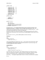
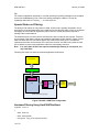
Special Notes on Filtering
The ability to filter frames is a key feature of CAN. A CAN node is typically interested in only a
small portion of the total data traffic on the CAN bus. By providing the ability to filter out unwanted
messages, the CAN node can significantly reduce the CPU cycles (and power) required to
manage CAN communications.
The hard filters and, to a lesser extent, soft filters have been created for this purpose. Therefore,
correct usage of the filters is critical to successfully implementing CAN. Shown in Figure 5 below,
hard CAN filters filter out CAN frames before they consume any CPU cycles. The software
implements soft filters and consumes CPU resources. However, soft filters can provide an extra
line of defense to prevent user application code from unnecessary execution.
Rule:
If no more than 16 filters are required, and data byte filtering is not required, use
only hard filters.
Following this simple rule ensures maximum application performance.
User Application
OEM API
Soft Filters
CPU
Hard
Filters
CAN
Protocol
Hardware
CAN Bus
Transceiver
Hardware
NovAtel OEM Positioning Engine
Figure 5 NovAtel’s CAN Filter Configuration
Hardware Filtering Using HardCANFilterStruct
typedef struct
{
BOOL bInUse;
BOOL bExtended;
unsigned long ulAcceptanceCode;
10 of 13
CAN Bus
APN-040 Rev 1
January 21, 2008
unsigned long ulAcceptanceMask;
} HardCANFilterStruct;
The code and mask bits used to define hardware filters are indicated in Table 1 below. A '1' bit
means, "This bit is used to define the code/mask".
Table 1: Hard Filter Code and Mask Bit Definitions
Extended Frames
Standard Frames
ulAcceptanceCode
0x1FFF FFFF
0x1FFC 0000
ulAcceptanceMask
0x1FFF FFFF
0x1FFC 0000
Bits 0-28 filter the 29-bit message identifier of extended frames if bExtended = TRUE. Bits 1828 filter the 11-bit message identifier of standard frames if bExtended = FALSE.
A '0' bit in the mask indicates that the corresponding bit in the code is used for acceptance
filtering. A '1' bit in the mask indicates that the corresponding bit in the code is not used for
acceptance filtering (that code bit may be ignored).
Extended frame examples:
ulAcceptanceMask = 0x1FFF FFFF
ulAcceptanceCode = 0xXXXX XXXX -> accept all messages regardless of
code bits (X = don't care)
ulAcceptanceMask = 0x0000 00F0
ulAcceptanceCode = 0x0000 0AX3 -> accept extended message IDs in the
range [A03, AF3] ([2563, 2803]10)
Software Filtering Using SWCANFilterStruct
typedef struct
{
unsigned long ulCode;
unsigned long ulMask;
unsigned short usExtCode;
unsigned short usExtMask;
} SWCANFilterStruct;
Apply software filters to CAN frame IDs in the same way as hard filters. The system integrator
can also simultaneously apply software filters to the first two data bytes of a CAN frame by
appropriately setting the bits of usExtCode and usExtMask. Table 2 on Page 12 indicates the
code and mask bits used to define software filters. A ‘1’ bit means, “This bit is used to define the
code/mask”.
11 of 13
APN-040 Rev 1
January 21, 2008
Table 2: Soft Filter Code and Mask Bit Definitions
Extended Frames
ulAcceptanceCode
0x1FFF FFFF
ulAcceptanceMask
0x1FFF FFFF
usExtCode
0x
FFFF
usExtMask
0x
FFFF
Bits 0-28 of the acceptance mask, and acceptance code, filter the 29-bit message identifier of
extended frames. Apply Bits 0-7 of the usExtCode and the usExtMask words to the first data
byte. Apply Bits 8-15 of the usExtCode and the usExtMask words to the second data byte.
A '0' bit in the mask indicates that the corresponding bit in the code is used for acceptance
filtering. A '1' bit in the mask indicates that the corresponding bit in the code is not used for
acceptance filtering.
Diagnostics
An essential component of creating a CAN application is to ensure that the system integrator can
test it. A loopback routine is available from NovAtel Customer Service upon request.
The loopback routine simultaneously transmits and receives CAN frames between CAN1 and
CAN2 configured for 1 Mbps/s. The system integrator must connect a properly configured CAN
bus between CAN1 and CAN2 (see Figure 1 CAN Physical Layers on Page 1).
Both CAN1 and CAN2 transmit extended frames at 2 ms intervals. The ID for frames transmitted
from CAN1 start at 0x10000000. The ID for frames transmitted from CAN2 start at 0x1FFFFFFF.
The ID increments by 1 after each successful transmission (OEM4API_CanSend() returns
TRUE). Note that a successful transmission does not necessarily indicate a successful reception.
The length of the data transmitted in each frame cycles from 0 to 8 bytes. Frame data bytes
contain the values in the range [0x30 to 0x37].
For every 100 frames CAN1 successfully transmits, the following message displays on COM1:
TX1/RX2 100/99/0, TX2/RX1 100/99/0
TX1/2 = the number of successful frame transmissions from CAN1/2
RX1/2 = the number of frames received on CAN1/2
CAN1 (TX1) transmits frames to CAN2 (RX2) and CAN2 (TX2) transmits frames to CAN1 (RX1).
The last parameter (0 in the example) is the number of frames lost. Calculate this number as:
number of lost frames = number of received frame IDs – number of expected frame IDs
For each frame the CAN successfully receives, the expected frame ID sets to the received frame
ID plus one.
On an error-free bus, the number of frames received from a CAN port are always 1 less than the
number of frames transmitted from the same CAN port:
RX2 = TX1 – 1
12 of 13
APN-040 Rev 1
January 21, 2008
Conclusion
The NovAtel receiver implements the CAN protocol using the NovAtel API and a third party CAN
protocol stack. The NovAtel API enables the system integrator to configure the CAN 2.0
processor with the appropriate filtering masks to permit interoperability of the NovAtel GNSS
receiver on a CAN bus network.
References
[1] See NXP Semiconductor Application Note for more details on the evolution of CAN:
http://www.nxp.com/acrobat_download/applicationnotes/AN92002.pdf
[2] http://en.wikipedia.org/wiki/CANopen
[3] http://en.wikipedia.org/wiki/DeviceNet
[4] The Application Program Interface (API) User Guide, with part number OM-20000074, is
available from NovAtel Customer Service when you have an API receiver model. NovAtel
contact details are in the Final Points section below.
[5] http://www.novatel.com/Documents/Manuals/om-20000093.pdf
[6] http://www.can-cia.org/index.php?id=517#c2068
[7] http://en.wikipedia.org/wiki/Controller_Area_Network
Final Points
If you require further information, regarding the topics covered by this document, please contact:
NovAtel Customer Service
1120 – 68 Ave. N.E.
Calgary, Alberta, Canada, T2E 8S5
Phone:
+1-800-NOVATEL (in Canada or the U.S.) or +1-403-295-4500
Fax:
+1-403-295-4901
E-mail:
[email protected]
Website:
www.novatel.com
13 of 13