1
Capacitor & Filter Bank
Protection Relay
RLC04
Operating & Instruction Manual
Document History
Revision
RLC04-BB-1.0
Date
2005-01-15
RLC04-BB-1.0
2007-07-26
Description
RLC04-B User Manual. Firmware Version 3.xx
RLC04-B User Manual. Firmware Version 3.xx
Changes: updated with new logo
About This Manual
These instructions cater for all possible contingencies likely to be met during installation, operation and
maintenance of the equipment.
However, should particular issues arise that are not covered sufficiently, and further information is required,
please contact the Technical Support Centre at Strike Technologies (Pty) Ltd.
Safety Symbol Legends
Draws attention to an operating procedure, practice, condition or statement, which, if
not strictly observed, could result in injury or death.
Draws attention to an essential operating procedure, practice or statement, which, if
not observed, could result in damage to, or destruction of, equipment.
Draws attention to an essential operating or maintenance procedure, or statement that must be
observed.
2
RLC04-B
Capacitor and Filter Bank Protection Relay
Complete Operating and Instruction Manual
3
4
Table of Contents
INTRODUCTION....................................................................................................................................................... 9
PRODUCT OVERVIEW .......................................................................................................................................... 10
Application ........................................................................................................................................................... 10
Main Product Features ........................................................................................................................................ 10
Protection Functions ........................................................................................................................................ 10
Test functions................................................................................................................................................... 10
Inputs ............................................................................................................................................................... 10
Outputs............................................................................................................................................................. 11
Enclosure ......................................................................................................................................................... 11
User Interface .................................................................................................................................................. 11
Data Communications...................................................................................................................................... 11
Application Software ........................................................................................................................................ 11
Product Evolution Information ............................................................................................................................. 11
FUNCTIONAL DESCRIPTION ............................................................................................................................... 12
Protection Functions............................................................................................................................................ 12
Normal Mode ................................................................................................................................................... 12
Repetitive Peak Overvoltage Protection ...................................................................................................... 12
Programmable vc>reset Time ...................................................................................................................... 13
Thermal Overcurrent Protection................................................................................................................... 14
Fundamental Frequency Star Point Unbalance Protection..........................................................................15
Fundamental Frequency Line Current Unbalance Protection...................................................................... 15
Fundamental Frequency Earth Fault Protection .......................................................................................... 16
Fundamental Frequency Overvoltage and Overcurrent Protection ............................................................. 16
RMS Overcurrent Protection ........................................................................................................................ 16
Fundamental Frequency Undercurrent Protection....................................................................................... 16
Breaker Fail Protection................................................................................................................................. 17
Capacitor Bank Re-switching Protection...................................................................................................... 17
Event Trip ..................................................................................................................................................... 17
H-Bridge Mode................................................................................................................................................. 18
Fundamental Frequency H-Bridge Unbalance Protection ........................................................................... 18
Inputs and Outputs .............................................................................................................................................. 19
Element Inputs ................................................................................................................................................. 19
Output Relays .................................................................................................................................................. 19
Relays K1 to K5............................................................................................................................................ 19
Relay K6 Self-supervisory Output ................................................................................................................ 19
Contact Forms.............................................................................................................................................. 19
Relay Checksum .......................................................................................................................................... 20
Digital Input ...................................................................................................................................................... 20
Breaker-Bon ................................................................................................................................................. 20
Event Tripping .............................................................................................................................................. 20
Remote Reset .............................................................................................................................................. 20
Other Facilities..................................................................................................................................................... 20
Password Protection ........................................................................................................................................ 20
Test Facilities ................................................................................................................................................... 20
PC Based Software Package........................................................................................................................... 21
Modbus Protocol .............................................................................................................................................. 21
5
Enclosure and Draw-out Unit............................................................................................................................... 22
Terminals ......................................................................................................................................................... 22
User Interface .................................................................................................................................................. 22
Five button keypad. ......................................................................................................................................23
Status LEDs ................................................................................................................................................. 23
LCD Display ................................................................................................................................................. 23
LCD Display ................................................................................................................................................. 24
Serial Data Port ............................................................................................................................................ 24
Auxiliary Power Supply........................................................................................................................................ 24
INSTALLATION AND COMMISSIONING.............................................................................................................. 25
Unpacking, Storage and Handling....................................................................................................................... 25
Enclosure and Draw-Out Unit..............................................................................................................................25
Configuring the Hardware Prior to Installation..................................................................................................... 26
Output relay contact form................................................................................................................................. 26
Mounting .............................................................................................................................................................. 26
Wiring................................................................................................................................................................... 27
Auxiliary power supply ..................................................................................................................................... 27
Current transformer circuits .............................................................................................................................27
Output Relay Circuits ....................................................................................................................................... 27
Digital Input ...................................................................................................................................................... 28
Serial Communication Port .............................................................................................................................. 28
Earth Connection ............................................................................................................................................. 28
Noise Isolation ..................................................................................................................................................... 28
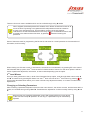
1st Level Menus ................................................................................................................................................... 30
2nd Level Menus................................................................................................................................................... 31
Changing or Selecting Parameters.................................................................................................................. 31
Some Exceptions ......................................................................................................................................... 31
Some Exceptions ......................................................................................................................................... 32
Scrolling ........................................................................................................................................................... 32
The Exit Process.............................................................................................................................................. 32
PROGRAMMING THE RLC04-B............................................................................................................................ 33
Configuring the Hardware.................................................................................................................................... 33
Setting the Password........................................................................................................................................... 33
Serial Port Options .............................................................................................................................................. 33
Serial Port Options .............................................................................................................................................. 34
Parameter Setup - Normal Mode ........................................................................................................................ 35
Set Element 1, 2, 3 Variables .......................................................................................................................... 35
Set Element 4 Variables ..................................................................................................................................36
Set Element 5 Variables ..................................................................................................................................36
Set Other Functions ......................................................................................................................................... 36
Compensate for Star Unbalance ..................................................................................................................... 37
Clear Trip History ............................................................................................................................................. 37
Output Relay Setup – Normal Mode ................................................................................................................... 37
Parameter Setup – H-Bridge Mode ..................................................................................................................... 38
Set Element 2, 3, 4 Variables .......................................................................................................................... 38
Set Other Functions ......................................................................................................................................... 39
Compensation for xIub.....................................................................................................................................39
Clear Trip History ............................................................................................................................................. 39
Output Relay Set-up - H-Bridge Mode ................................................................................................................ 40
6
OPERATING THE RLC04-B .................................................................................................................................. 41
Healthy Condition ................................................................................................................................................ 41
The LED Indicators .......................................................................................................................................... 41
The Running Displays...................................................................................................................................... 41
Normal Mode Displays ................................................................................................................................. 42
H-Bridge Displays......................................................................................................................................... 42
Default Display ............................................................................................................................................. 43
Fault Condition .................................................................................................................................................... 43
The LED Indicators .......................................................................................................................................... 43
The Running Display........................................................................................................................................ 43
Post-trip Fault Annunciation Displays .............................................................................................................. 43
Typical Post-Trip Annunciation Displays...................................................................................................... 44
Information Retrieval ........................................................................................................................................... 44
Trip History List ................................................................................................................................................ 44
Status Information............................................................................................................................................ 45
Relay configured in Normal Mode................................................................................................................ 46
Relay configured in H-Bridge Mode: ............................................................................................................ 46
Clearing the Counters .................................................................................................................................. 46
TESTING AND TROUBLESHOOTING .................................................................................................................. 48
Automatic Self-testing.......................................................................................................................................... 48
User-performed Diagnostic Tests........................................................................................................................ 48
Injection Testing .................................................................................................................................................. 49
Trouble Shooting ................................................................................................................................................. 50
APPENDIX 1 ........................................................................................................................................................... 51
Table 1 - Step-By-Step Installation Instructions .................................................................................................. 51
Table 3: Nomenclature & Definitions for H-Bridge Mode .................................................................................... 54
Table 4: General Characteristics......................................................................................................................... 55
Table 5: Technical Specifications........................................................................................................................56
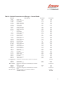
Table 6: Settable Parameters and Ranges – Normal Mode ............................................................................... 57
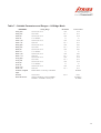
Table 7 – Settable Parameters and Ranges – H-Bridge Mode........................................................................... 58
APPENDIX 2 ........................................................................................................................................................... 59
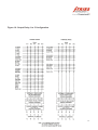
Example 1: Calculation of Checksums for Output Relays 1 To 5 ....................................................................... 59
Typical Examples of Output Relay Settings and Resulting Checksums ......................................................... 59
One of 5 Output Relays in Normal Mode Operation .................................................................................... 59
One of 5 Output Relays in H-Bridge Mode ...................................................................................................... 59
Example 2: RLC04-B Setting Calculations.......................................................................................................... 60
20 Mvar harmonic filter with a double star capacitor bank .............................................................................. 60
Settings ............................................................................................................................................................ 61
Notes on Settings............................................................................................................................................. 61
Example 3: Calculation of the Reactor Heating and Cooling Time Constant (W)................................................. 64
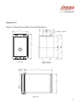
Appendix 3........................................................................................................................................................... 65
Figure 1: Relay Case and Panel Cut-out Dimensions......................................................................................... 65
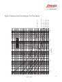
Figure 3: Repetitive Peak Overvoltage vs. Trip Time Curves ............................................................................. 66
Figure 3: Repetitive Peak Overvoltage vs. Trip Time Curves ............................................................................. 67
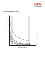
Figure 4: Thermal Trip Time Curves ................................................................................................................... 67
Figure 4: Thermal Trip Time Curves ................................................................................................................... 68
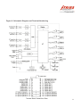
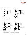
Figure 5: Typical Application Examples .............................................................................................................. 69
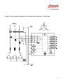
Figure 6: Typical Wiring Diagram For A Double Star Capacitor / Filter Bank ..................................................... 69
7
Figure 6: Typical Wiring Diagram For A Double Star Capacitor / Filter Bank ..................................................... 70
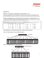
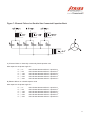
Figure 7: Element Failure in a Double Star Connected Capacitor Bank............................................................. 71
Figure 8: Typical Wiring Diagram for an H-Bridge Capacitor / Filter Bank.......................................................... 72
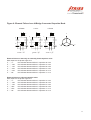
Figure 9: Element Failure in an H-Bridge Connected Capacitor Bank................................................................ 72
Figure 9: Element Failure in an H-Bridge Connected Capacitor Bank................................................................ 73
Figure 10: Output Relay 1 to 5 Configuration...................................................................................................... 74
8
Introduction
The RLC04-B is a capacitor and filter bank protection relay. It has been built on the foundation of years of
continued development through previous successful models. The RLC04-B has quality embedded into every
stage of its design and it has been manufactured to the strictest quality standards. Combining state of the art
hardware technology and software techniques it provides the most convenient functionality in its sphere.
This manual contains an overview, functional description, and specification of the RLC04-B, as well as detailed
instructions on installation, commissioning, setting up, operation, and maintenance.
Whilst it provides a wealth of information, this manual does not replace the need for anyone installing, operating,
or maintaining the equipment to be suitably qualified and/or trained. Such a person should have a prior
knowledge of power system protection, power system measurements, and power system safety procedures.
Before installing, setting up or operating the RLC04-B, the user should study the applicable sections of this
manual, taking particular note of WARNINGS, CAUTIONS and NOTES included for the safety and protection of
both personnel and equipment.
Before attempting to troubleshoot the equipment, the user should thoroughly understand the entire manual. For
troubleshooting and commissioning the following equipment is required:
- Digital multimeter with clip-on current tong for measuring 1A or 5A current transformer secondary.
- Preferably a three-phase, alternatively a single-phase, primary or secondary injection test set, which is
included in the product range offered by Strike Technologies.
Due to the nature of the RLC04-B relay, it is not recommended that the user should attempt repairs other than
the removal and replacement of the draw-out unit that houses all electrical and electronic parts. Any faulty
RLC04-Bs should be returned to Strike Technologies (Pty) Ltd. for testing, and if necessary, for repair or
replacement of faulty parts, re-calibration and re-testing.
Thank you for purchasing the RLC04-B protection relay, please contact Strike Technologies (Pty) Ltd for further
details should they not be covered within this manual
9
Product Overview
Application
The RLC04-B Protection Relay provides comprehensive protection for the capacitive, inductive and resistive
elements of three phase medium voltage and high voltage shunt capacitor banks and harmonic filter circuits. The
capacitor banks consist of several individual capacitors in a series – parallel arrangement. Each individual
capacitor within a bank may be internally fused, externally fused or unfused. A number of banks are constructed
as a single star, double star, delta or H-bridge configuration.
In normal conditions these banks are balanced, i.e. each leg draws the same current as near as practically
possible. Should one or more of the capacitor elements fail, the system will become unbalanced and the RLC04B will sense this and can be used to trip any necessary circuit breakers.
The RLC04-B has additional protection features such as for fundamental and harmonic overcurrent and
overvoltage, as well as over temperature conditions and residual earth currents.
Due to its accuracy and short response times, the relay provides the optimum protection for a system. By only
operating when absolutely necessary it prevents unnecessary trip outs thereby preventing unnecessary financial
losses and other detrimental consequences. In addition, after a system fault or equipment failure, the RLC
Protection Relay trips the associated circuit breaker timorously, to ensure maximum personnel safety, and to
minimize further equipment and other consequential damage.
Main Product Features
Protection Functions
Repetitive peak overvoltage
Thermal overcurrent
Fundamental frequency overvoltage and overcurrent
RMS overcurrent
Fundamental frequency star point unbalance
Fundamental frequency line current unbalance
Fundamental frequency H-bridge configuration unbalance
Fundamental earth fault current
Fundamental frequency undercurrent
Breaker Fail detection
Capacitor bank re-switching
Event tripping
Test functions
Both on-line and user activated hardware diagnostic testing
Inputs
4 Dual Current Measuring Elements - Individually programmable for either 1A or 5A
Optically isolated digital blocking input - User configurable for active low/active high
Wide range AC/DC Auxiliary Power Supply (30 – 250V AC/DC)
10
Outputs
5 Trip/Alarm output relays (K1 to K5), programmable with regard to energisation and latching functionality,
hardware configurable NO/NC contact form
1 Dedicated self-supervisory output relay (K6), hardware configurable NO/NC contact form
Enclosure
Flush mount and 19” rack compatible
Draw-out facility, with automatic shorting of CT input connections
User Interface
3 LED Status Indication: Healthy (Green); Alarm/Start (Yellow); Trip (Red)
Alpha-numeric, backlit, Liquid Crystal Display (2 lines x 16 characters)
Menu driven user interface with 5 button interactive keypad
Data Communications
Two serial interfaces for programming and interrogation
Remote communication by means of RS232 or RS485, either via a dedicated line or via a modem (PSTN or
GSM).
Both Strike protocol and Modbus RTU protocol co-reside in the product
Application Software
Windows 95/98/2000/NT/XP Software Package, for local programming/data uploading, as well as remote
communication via modem
Product Evolution Information
Released in early 2005, the RLC04-B replaces the earlier RLC Version 3 model. Although similar in overall
functionality, there have been many major upgrades in hardware, specification, and operation to its predecessor.
“One relay fits all”. All of the features that were previously optional when ordering the relay, are now
programmable via the set up menu. This means that there is only one version of this relay, which helps reduce
your stockholding and offers the greatest flexibility should operating conditions change. The new application
software addresses these new features.
The following are just some of the features that are new in the RLC04-B:
o Normal Mode or H-Bridge Mode is now programmable in the same unit
o 50Hz or 60Hz operation is now programmable
o 1A/5A CT selection is now programmable – no external wiring to change
o A second serial port (RS232) has been positioned on the front panel for ease of connection to a lap-top
computer. This port is used for any communication with the unit, including Strike PC software or
MODBUS, and in particular for firmware upgrades.
o The serial port on the rear of the unit is now RS232/RS485 programmable. This port can be used for
Strike PC software or MODBUS.
o Both serial ports are separately programmable to baud rates of 2400 to 115200
o Greater accuracy of time and current measurements
o Much improved response time
o Time stamping of the trip history records and certain other status registers
o The digital input can be configured as one of three alternative functions; Breaker on sensing, an event
input, or for remote reset
o Lost password recovery procedure avoids having to return the product to the factory for re-initialisation.
11
Functional Description
Protection Functions
Shunt capacitor and filter banks are used in medium and high voltage systems to provide power factor correction
and reduce unwanted harmonics being fed back onto the mains grid. Any one of a number of standard circuitries
can be used to provide capacitor or filter bank protection in a system. With its 4 Analogue Input Elements, 1
Digital Input, 5 output relays for system protection, and 1 output relay for self-supervision purposes, the RLC04-B
can be programmed to handle any of these configurations.
The measured currents themselves, or several other values calculated from them, are compared to threshold
values entered into the RLC04-B by the user. These can be alarm, low-set, or high-set thresholds, although not
all threshold types are relevant to all functions. If a threshold value is exceeded, a start signal is immediately
generated, which in itself can be used to activate one or more output relays, and a timer linked to that function
starts running. Should the threshold remain exceeded for a specified time-out period, normally also entered by
the user, an alarm or trip signal will be generated. The RLC04-B can be programmed to respond by switching
any permutation of the output relays for each particular signal/threshold combination.
The relay’s functionality and programmable options adapt according to the type of circuitry being protected. We
therefore need to describe the two major circuit groups separately in the following sections.
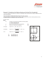
Normal Mode
This mode is applicable to star, delta, and double star circuits.
Iub
or
Repetitive Peak Overvoltage Protection
The dielectric of a capacitor bank is stressed by the repetitive peak voltage applied to it. According to recognized
standards, a capacitor bank (and its individual elements) must be able to withstand an RMS sinusoidal voltage of
110% of its rated voltage at rated frequency for extended periods.
Thus a capacitor can withstand a repetitive peak voltage of 1.1·¥2·UN for extended periods.
A capacitor can withstand even higher voltages for short periods. The Temporary Overvoltage Withstand curve
defines the time the capacitor can survive such overvoltage before failure (Refer to Figure 3 in Appendix 3). This
curve has been derived from the relevant ANSI and IEC recommendations.
In operation, the RLC04-B measures the fundamental frequency current flowing in the capacitor banks in each of
the three phases, as well as any super-imposed harmonics (up to the 50th). These current measurements are
then integrated to provide the repetitive peak voltages VC for each capacitor bank. This value VC is then
compared to three adjustable thresholds:
12
The alarm threshold VC>al/vcr, with an associated adjustable definite time-out period, VC>al: xt; if VC exceeds
the threshold for the time set, the alarm signal VC>alarm is generated.
The low-set threshold, VC>/VCR. For voltages above this threshold, a starter signal, vc>start starts a trip timer.
The ANSI inverse time curve defines the time before the low-set trip signal, vc>trip, is generated, and providing
that the voltage still exceeds the threshold.
The high-set threshold, vc>>/vcr, with an associated adjustable definite time-out period vc>>:xt, is available to
provide a high-set trip output vc>>trip, if the associated threshold is exceeded for the definite time set.
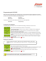
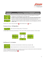
Programmable vc>reset Time
In the second situation above, when the low-set threshold vc>/vcr is exceeded, the trip timer is started. If the
overvoltage recovers to below the set threshold before the trip timer times out, no trip occurs but the trip timer is
not cleared, but rather is held for a programmable reset time, vc>reset, before resetting. Should the threshold be
exceeded again before expiry of this reset time, the trip timer starts incrementing from its previous value. This
means that such a condition can still result in a trip because of the prior accumulated count value in the trip timer.
This helps take care of the “memory effect” of capacitors. If this feature is not required, vc>reset can be set to
zero.
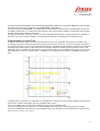
The graphs show a sequence of intermittent overvoltages in a monitored circuit, with two different consequences
for the relay condition dependent upon the vc>reset value chosen:
The vc/vcr voltage ratio, occasionally exceeding the low-set trip threshold value.
The accumulating trip timer value with a shorter vc>reset value, allowing an intermediate trip timer reset.
The accumulating timer value with a longer vc>reset value, thus allowing no intermediate reset of the trip timer,
and eventually creating a trip condition.
13
Thermal Overcurrent Protection
All of the components making up a capacitor bank / harmonic filter circuit are stressed thermally by the current
Irms which flows through them. This applies to all of the elements such as circuit breaker, feed cable, damping or
filter reactors, and filter resistors, as well as the capacitors. Irms comprises both the fundamental and harmonic
components. The RLC04-B protects the banks against such excessive temperature rise which would otherwise
lead to damage of the components and cause a breakdown.
According to recognized standards, a capacitor bank, and the capacitor units making up the bank, must be rated
to withstand a continuous current of 130% of the rated current.
For each phase, the RLC04-B protects a capacitor bank / harmonic filter circuit from excessive current stressing,
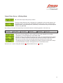
by modeling the thermal response of the circuit to the total heating current, Irms.
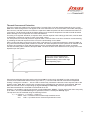
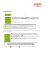
After a system has been running for a short while, it will heat up to a particular temperature, caused by Irms. At
any point before that steady state condition is reached, the lower temperature of the system so far attained could
be said to be caused by a lower effective thermal current, represented as Ith. When the system eventually
reaches the steady state condition, Ith equals Irms. The time constant which determines how quickly this occurs
depends upon the system.
Irms is the actual instantaneous
measured current, while Ith is the
effective heating current which lags
Irms depending upon .
Using advanced digital signal processing techniques Irms is continuously calculated from the measured line
th
currents, both fundamental and harmonics (up to the 50 ). A second order thermal model with an adjustable
heating / cooling time constant , is then used to continuously calculate the thermal current response, Ith, to the
heating current, Irms. Ith is continuously compared to the adjustable low-set and high-set thresholds, Ith> and
Ith>>, each linked to their corresponding trip signals Ith>trip, and Ith>>trip, which are generated, if the
associated thresholds are exceeded for the definite times set.
However, it is possible to set the low-set time-out period Ith>:xt to “Alarm”. The low-set function then acts purely
as an alarm, and only the Ith>start signal is generated, without a subsequent Ith>trip signal.
The trip times can be evaluated using the following formula:
ҏ -ln (((I/Ith>)² - 1) / ((I/Ith>)² - (Io/Ith>)²))
t/ =
where I/Ith> = overload current / thermal trip threshold current
and
Io/Ith> = pre-load current / thermal trip threshold current
14
Fundamental Frequency Star Point Unbalance Protection
In a double star connected capacitor bank, the failure of internal capacitor elements, and the subsequent blowing
of internal capacitor element fuses or external capacitor unit fuses, is detected by sensitive monitoring of the
unbalance current flowing between the two star ppoints.
Even though efforts may be taken to balance a double star connected capacitor bank, by optimum selection and
positioning of the capacitor units making up the bank, the tolerance in capacitance is such that a “natural”
fundamental frequency star pointt unbalance current flows under normal conditions.
The RLC04-B measures the star point unbalance current and calculates the fundamental frequency component,
Iub. This can then be compensated, in magnitude and phase angle, to zero, to enable further changes, in both
magnitude and phase angle, ¨Iub, from the initial uncompensated value, to be determined. The magnitude of
¨Iub is a measure of the change in capacitance in any leg of a double star capacitor bank arrangement, whereas
the phase angle of ¨Iub indicates the leg in which the change in capacitance has occurred.
The magnitude of (¨)Iub is continuously compared to an adjustable alarm threshold, Iub_al, and trip thresholds,
Iub> and Iub>> each with associated adjustable definite time-out periods, Iub_al:xt, Iub>:xt and Iub>>:xt
respectively. Where (¨)Iub exceeds Iub_al for the definite time set, an alarm signal,
Iub_alarm, is generated. In addition, a starter signal Iub>start as well as low-set and high-set trip signals,
Iub>trip, and Iub>>trip, are generated, if the associated thresholds are exceeded for the definite times set.
If the natural unbalance has been compensated and the fundamental current in the reference
phase (Element1) drops below 10% of the nominal current In, the star point unbalance protection
functions are suspended, and the compensation vectors are ignored.
If the natural unbalance is not compensated and the fundamental current in the reference phase
drops below 10% of the nominal current In, the star point unbalance protection function operates
only on the amplitude of the measured unbalance current – the phase angle will not be taken into
consideration.
The advantage of star point unbalance protection is that, unlike line current unbalance, the magnitude and phase
angle of (¨)Iub is not influenced by any phase imbalance in the supply voltage. Therefore the sensitivity can be
much higher than line current unbalance measurement, without spurious tripping caused by unbalanced supply
voltages. This sensitivity is often essential for adequate protection of larger capacitor banks with both
internal/external and unfused capacitor units.
In addition, the star point unbalance protection function indicates the leg of the double star bank in which the
change in capacitance has occurred. This is particularly convenient for larger capacitor banks with internally
fused or unfused capacitor arrangements, to speed up the identification of faulty capacitor units. Refer to Figure 7
in Appendix 3 for more details on this.
Fundamental Frequency Line Current Unbalance Protection
The monitoring of fundamental frequency line current unbalance provides a means of detecting changes in
impedance resulting from failures and faults within the capacitive, inductive and resistive elements of a capacitor
bank / harmonic filter circuit. These faults or failures invariably result in an unbalance in the fundamental
frequency component of the line currents.
The RLC04-B calculates the fundamental frequency line unbalance, Ilub, from the fundamental frequency
components of the three phase line currents. Ilub is continuously compared with two adjustable thresholds, Ilub>
and Ilub>>, each with an associated adjustable definite timer, Ilub>:xt and Ilub>>:xt.
15
For Ilub greater than Ilub>, a starter signal, Ilub>start, is generated. In addition, low-set and high-set trip
signals, Ilub>trip and Ilub>>trip, are generated if the associated thresholds are exceeded for the definite times
set.
The sensitivity of line current unbalance protection is limited by the effect of supply voltage unbalance on the line
currents. Nevertheless, line current unbalance protection is useful as back-up protection to star point unbalance
protection, as well as for early detection of filter resistor and reactor faults, and for early detection of capacitor
element failures in smaller capacitor banks, in single star or delta connected arrangements, where star point
unbalance protection is not provided.
Fundamental Frequency Earth Fault Protection
The RLC04-B calculates the fundamental frequency residual or earth fault current, Io, as the magnitude of the
vector sum of the three fundamental frequency components of the three phase line currents. Io is compared with
two adjustable thresholds, Io> and Io>>, each with an associated adjustable definite time-out period, Io>:xt and
Io>>:xt. For Io greater than Io>, a starter signal, Io>start, is generated.
In addition, low-set and high-set trip signals, Io>trip and Io>>trip, are generated if the associated thresholds are
exceeded for the definite times set.
Fundamental Frequency Overvoltage and Overcurrent Protection
In the absence of any equipment failures or system faults, the fundamental frequency line currents flowing in a
shunt connected capacitor bank / harmonic filter circuit are proportional to the fundamental frequency supply
voltage.
For each phase, the RLC04-B calculates the fundamental frequency component, I1, of the line current. I1 is
continuously compared with two adjustable thresholds, I1> and I1>>, each with an associated adjustable definite
time-out period, I1>:xt and I1>>:xt. For I1 greater than I1>, a starter signal, I1>start, is generated. In addition,
low-set and high-set trip signals, I1>trip and I1>>trip, are generated if the associated thresholds are exceeded
for the definite times set.
The low-set fundamental frequency overcurrent threshold is typically set a little higher than the current that would
flow at the maximum system voltage, e.g. at say 107,5% of nominal, with a fairly long definite time setting of, say
300 seconds. This protects the capacitor bank/harmonic filter circuit from an abnormally high supply voltage, in
excess of the declared maximum system voltage.
A fundamental frequency line current much higher than that which would normally flow at the maximum system
voltage, indicates a catastrophic phase-to-phase, three phase or phase-to-earth fault, or major equipment failure,
requiring immediate disconnection of the capacitor bank / harmonic filter circuit. Therefore the high-set
fundamental frequency overcurrent threshold is typically set at, say 150% of nominal, with a much shorter time
delay setting.
RMS Overcurrent Protection
For each phase, the RLC04-B calculates the RMS current, Irms, comprising both the fundamental and harmonic
components of the line current. Irms is continuously compared with two adjustable thresholds, Irms> and
Irms>>, each with an associated adjustable definite time-out period, Irms>:xt and Irms>>:xt.
For Irms greater than Irms>, a starter signal, Irms>start, is generated. In addition, low-set and high-set trip
signals, Irms>trip and Irms>>trip, are generated if the associated thresholds are exceeded for the definite times
set.
Fundamental Frequency Undercurrent Protection
If the mains power supply should fail, while the capacitor bank / harmonic filter circuit breaker is on (Digital input
“active” and configured as “Breaker on“), then it is prudent to trip the capacitor bank / filter circuit breaker. After
restoration of the mains supply, the bank can then be re-energized under controlled conditions, after the system
16
load has been re-established. In certain cases this can help to avoid over correction and excessive voltage rise,
due to load rejection during a mains power dip.
For each phase, the RLC04-B calculates I1, the fundamental frequency component of the line current. I1 is
continuously compared with an adjustable undercurrent threshold, I1<, and associated adjustable definite timeout period, I1<:xt. With the capacitor bank / harmonic filter circuit breaker on, if the mains power supply fails, as
indicated by a drop in I1 below I1< for longer than the definite time set, then the undercurrent trip signal, I1<trip,
is generated.
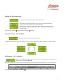
Breaker Fail Protection
Bfail1
Any one of the following conditions can be selected to signal successful breaker operation:
[1]
[2]
[3]
[4]
Ifund<10% of In
Dig-Input
Ifund OR Input
Ifund AND Input
a drop in the fundamental currents below 10%
a change of the digital input from active to inactive
logical OR combination of [1] and [2]
logical AND combination of [1] and [2]
If the selected condition is not fulfilled within a programmable time-out period, Bfail1:xt, after the RLC04-B
issues a trip output, a Bfail1 signal is generated which can be allocated to one or more of the output relays.
For selections which involve the digital input, the input function must be set to “Breaker-Bon” or else the release
function will be default to Ifund<10%In.
Bfail2
In addition to the above, if I1 remains above 10% of rated In, for longer than the adjustable definite time-out
period, Bfail2:xt, after the breaker switches off (digital input set to “Breaker- Bon” - indicates the breaker
open/close status), then this indicates a major failure of the capacitor bank / harmonic filter circuit breaker, and
the breaker fail signal, Bfail2, is generated.
Both signals can be used to trip an upstream breaker.
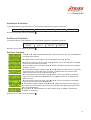
Capacitor Bank Re-switching Protection
When a capacitor bank / harmonic filter circuit breaker switches off for any reason, it should not be re-energized
until the capacitor bank has discharged. This will prevent severe and stressful voltage and current transients due
to the application of mains supply voltage onto a charged capacitor bank.
The RLC04-B provides the necessary logic, and a breaker enable output signal, Bena, to inhibit the reenergization of the circuit breaker, for an adjustable definite time, Bena:xt, since de-energization.
Bena can be triggered by a choice of the following:
[1]
[2]
[3]
[4]
Ifund<10% of In
Dig-Input
Ifund OR Input
Ifund AND Input
a drop in the fundamental currents below 10%
a change of the digital input from active to inactive
logical OR combination of [1] and [2]
logical AND combination of [1] and [2]
Bena can be allocated to one or more of the output relays.
This allows the user to configure the RLC04-B in the most suitable way for the application.
Event Trip
The RLC04-B offers the possibility to trip the relay from an external signal via its digital input. A precondition is
that the digital input must be configured as an Event trip input. If the digital input changes its state from inactive to
active for the definite time-out period Event:xt, the generated function, Event_trip, can be used to operate any
of the output relay(s).
17
H-Bridge Mode
Fundamental Frequency H-Bridge Unbalance Protection
The RLC04-B offers this mode to provide sensitive unbalance protection independently
for each phase of an H-Bridge configured capacitor bank.
Even though efforts may be taken to balance an H-bridge capacitor bank by optimum
selection and positioning of the capacitor units, the manufacturing tolerance in
capacitors is such that a “natural” fundamental frequency unbalance current flows
under normal conditions.
Iub
The unbalance currents are measured in each phase of an H-bridge configured
capacitor bank. Out of these values the fundamental frequency components aIub, bIub
and cIub, are calculated. These can then be compensated in amplitude and phase
angle to zero, to enable further changes in both magnitude and phase angle, ¨aIub,
¨bIub and ¨cIub, from the initial uncompensated value, to be determined.
The magnitude of ¨aIub, ¨bIub or ¨cIub is a measure for the change in capacitance, while the phase angle
indicates the leg in which the change in capacitance has occurred.
The magnitudes of (¨)a/b/cIub are continuously compared to adjustable alarm thresholds a/b/cIub_al, low set
trip thresholds a/b/cIub>, and the high set trip thresholds a/b/cIub>>. Each of these thresholds is linked to an
associated adjustable definite time-out period, a/b/cIub_al:xt, a/b/cIub>:xt, and a/b/cIub>>:xt respectively.
For (¨)a/b/cIub greater than a/b/cIub_al for the definite time set, an alarm signal, a/b/cIub_alarm, is generated.
Similarly, starter signals a/b/cIub>start and low-set and high-set trip signals, a/b/cIub>trip, and a/b/cIub>>trip,
are generated, if the associated thresholds are exceeded for the definite times set.
If the natural unbalance has been compensated and the fundamental current in the reference
phase (Element1) drops below 10% of the nominal current In, the H-bridge unbalance
protection functions are suspended, and the compensation vectors are ignored.
If the natural unbalance is not compensated and the fundamental current in the reference phase
drops below 10% of the nominal current In, the H-bridge unbalance protection function
operates only on the amplitude of the measured unbalance current – the phase angle will not be
taken into consideration.
The advantage of H-Bridge capacitor bank unbalance protection is that the magnitudes and phase angles of
¨aIub, ¨bIub and ¨cIub are not influenced by any phase imbalance in the supply voltage. Therefore the
sensitivity can be much higher than line current unbalance measurement, without spurious tripping caused by
unbalanced supply voltages. In addition, this sensitive unbalance protection is now provided independently for
each phase of the capacitor bank, thus making it possible to immediately and independently identify the phase
and branch in which a change in capacitance has occurred. This is particularly convenient for larger capacitor
banks with internally fused or unfused capacitor arrangements, to speed up the identification of faulty capacitor
units.
Refer to the figures 5, 8, and 9 in Appendix 3 for further information on this function.
18
Inputs and Outputs
Element Inputs
Four measuring inputs (Elements 1 to 4) are provided. Each can be programmed to measure inputs from current
transformers with nominal currents In of either 1A or 5A.
In Normal Mode the Elements 1, 2 and 3 are used to measure the line currents while Element 4 is used to
measure the star point unbalance current of a double star connected capacitor bank.
In H-Bridge Mode the Element 1 is used to measure the reference phase current, while Elements 2, 3 and 4 are
used to measure the unbalance currents in each of the phases of the H-configured capacitor bank.
Refer to Figure 5 in Appendix 3 for typical configurations.
When programming the RLC04-B it will be noticed that under the Parameter Set-up menu is a sub-menu entitled
Set Element 5 variables. Element 5 is a “virtual” and not a physical element. The currents “measured” by this are
Io and Ilub which are calculated from the line currents measured by elements 1-4.
Output Relays
The RLC04-B has six relay outputs. Five outputs K1 to K5 are for normal protection use, while the sixth K6 is for
the RLC04-B to check its own “health”. To confirm the correct allocation of these output relays a checksum
function is available in the unit.
Relays K1 to K5
Relays K1 to K5 can be programmed, separately and in any permutation, to operate in reaction to any alarm/start
or trip condition.
The relay outputs can be hardwired to N/O or N/C settings by using the selecting the appropriate links on the
RLC04-B’s PC board. See the relevant section under Installation and Commissioning.
Output relays K1 - K5 can be programmed to be de-energised or energised in the operational healthy state, and
to be latching or non-latching.
For relay contact ratings, refer to Table 5 in Appendix 1. Note that in the RLC04-B product, relay K1 has a higher
dc switching capability than K2 to K5, and is intended for the direct tripping of certain switchgear. Caution should
be exercised, however, not to exceed the contact ratings of any relay, as this will eventually result in contact
failure.
Relay K6 Self-supervisory Output
Relay K6 output is the RLC04-B self-supervisory relay, and its functionality is not user configurable, apart from
the N/O or N/C hardware option by using the relevant PC board link.
Output Relay K6 is energised in the healthy power-up normal condition, and de-energises on:
o Loss of auxiliary power supply
o Failure of the RLC04-B internal power supply
o Failure of the microprocessor hardware, software, or memory.
Contact Forms
Output relays 1 to 6 each have one changeover (form C) contact. As default, output relays 1 to 6 are supplied
with the normally open (relay de-energized) contacts wired to the terminal block. However, the user may easily
change the contacts of any or all of output relays 1 to 6 wired to the terminal block to be normally closed, as
required by the application. Refer to Section 5 – Installation and Commissioning for more details on this.
19
Relay Checksum
Each relay K1 to K5 has an associated checksum which is calculated automatically according to the allocations
made during set-up. This calculated checksum is displayed as part of the set-up screens. The purpose is for the
user to be able to confirm the correct set-up of K1 to K5, by manually calculating the checksum representing the
desired relay set-up and then comparing this with the calculated checksum, which must agree. Refer to Example
1 in Appendix 2 for more details on this.
Digital Input
In addition to the four measuring elements there is an optically isolated digital input, in which the input signal is
not measured but is simply detected to see if it is active or inactive. It can be set to have a high level or a low
level as being active. A high level must conform to the range 30V - 250V ac or dc and is not polarity sensitive. It
can be configured as one of three possible functions, or disabled.
Breaker-Bon
A signal from an auxiliary contact on the associated circuit breaker is fed into the digital input to signal whether
the breaker is open or closed. This signal is used by the undercurrent protection, and can be used by the Breaker
Fail 1 protection and Bena function of the relay. If the relay does not receive the Breaker On signal, neither of the
mentioned functions will operate.
Event Tripping
The second alternative for the digital input is to create a trip condition based on an active signal on its input. The
same input conditions as described above apply, and similarly to other trip condition configurations, any
combination of output relays K1 to K5 can be allocated to it. To create a trip, the active signal must remain valid
for a pre-set length of time. This Event Input Trip Time (Event:xt) is programmable under the PARAMETER
SETUP – Set OTHER functions menu. Should the signal become inactive during this trip time, further activation
will begin a new timing sequence starting from zero, even if the reactivation occurs within the original trip time. A
suitably descriptive label, downloadable from a computer running the application software, can be programmed
to appear following an event trip.
Remote Reset
The third alternative for the digital input is to reset the RLC04-B from a remote location, e.g. a control room. This
has the same effect as pressing the red button to acknowledge a trip.
Other Facilities
Password Protection
Certain parts of the menu structure can be protected by an optional password. This provides a measure of
security against inadvertent or unauthorized alterations to the relay settings, or clearance of the trip history.
Unrestricted access is still provided to the status and test functions.
Test Facilities
While the RLC04-B Relay is in service, it continuously performs various self-testing functions, and if any errors or
failures are detected, the corresponding error code(s) will be displayed, and the self-supervision output relay will
de-energize, to signal the malfunction. These self-tests include tests of the processors as well as the memory of
the device. All protection functions continue uninterrupted during this process.
20
In addition, a further set of hardware diagnostic tests may be performed on the RLC04-B by the user to test and
check the functionality of the digital input, relay outputs, LCD display and LED’s. Note that some protection
functions may be interrupted during this process.
PC Based Software Package
A Windows 95/98/ME/2000/NT/XP based software package is available for the RLC04-B to exploit its
communication facilities. This software package enables the user to create, edit, save, open and print any
number of the RLC04-B set-up files on a PC, and to download or upload a set-up file to or from the relay, either
directly or via a modem. This is carried out using the Strike communications protocol. In addition, all the other
facilities and functions of the serial data port can be exploited using this software package.
Modbus Protocol
The RLC04-B supports the MODBUS RTU protocol for integration of the relay into a SCADA environment.
Further information on the implementation can be provided upon request.
21
Hardware Description
Enclosure and Draw-out Unit
The RLC04-B is housed in a draw-out chassis within a fixed case. This housing is particularly suitable for both
flush mounting and 19 inch rack mounting. The case is designed for use in tropical climates, and is designed to
withstand shock, vibration and the ingress of dust and moisture. Two phosphor bronze earth continuity strips
riveted to the draw-out chassis make contact with earthing strips in the fixed case.
Terminals
A terminal block, with 28 recessed terminals, is provided on the rear of the fixed case. Standard M4 screw
terminals (cable lugs with M4 and lug outer diameter < 8 mm), or fast-on connectors (4,8 mm width / 0,8 mm
thickness), can be used on the terminal block for connections to the protection relay. Removing the draw-out
chassis from the fixed case automatically short circuits the current transformer field terminals, before breaking
contact with the draw-out chassis, and ensures that the current transformer circuits are not open circuited during
and after removal.
The RLC04-B incorporates static sensitive devices. However the electronic circuits
are well protected by the fixed metal case. Therefore do not withdraw the draw-out
chassis unnecessarily. Refer to the section on Installation for further details on
handling of the draw-out chassis when removed from the fixed case.
User Interface
A menu driven interface is provided on the front panel. This allows convenient viewing of operational information
as well as programming facilities for relay set-up, and access to certain test aids for verification purposes.
22
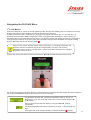
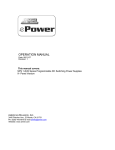
LCD Display
Status LEDs
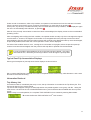
5 button keypad
Front serial port
Five button keypad.
The four black buttons are for scrolling left, right, up and down, and the red button is an “Accept” or “Enter”
button, for confirming an entry or value, during set-up, for navigating backward or forward in the menu structure,
or for accepting a trip annunciation condition, to allow the display to resume its normal running status.
The up and down buttons are used for scrolling through values during set-up. Holding the button in will result in
the scroll speed increasing.
Status LEDs
There are three status indicators:
Power On (Healthy). This green LED is normally on continuously indicating that power is applied, and the relay
is in a healthy state. A flashing state indicates that the relay is in the process of completing its on-line diagnostic
test.
Alarm/Start. This Yellow LED may be illuminated by an Alarm or a Start condition, depending upon the set-up of
the relay.
Trip. This red LED is illuminated when a trip condition occurs and remains on until the trip condition, with its posttrip display, is cancelled by pressing the red “accept” button on the keypad. If multiple trip conditions were
present at the time of trip, each condition must be sequentially accepted before the red LED will go off.
The value of the Ith>:xt can be set to “Alarm”. This is only used to signal the alarm condition
via one of the output relays. It is not linked to the yellow LED.
23
LCD Display
This 2 line x 16 character alpha-numeric display provides most of the information feedback to the operator. It has
a backlight which extinguishes after 1 minute of keypad inactivity. Pressing any button after this will light the
display once more. The function of that button is ignored for this purpose.
It supplies the following information:
o During normal relay operation – the display of various measured and calculated parameters, together
with the low-set thresholds associated with these parameters.
o After a relay trip condition – annunciation of the entire fault conditions, including the value of the fault
currents and voltages at the instant of trip, the information in which phase the max. / min. value occurred
and the relay trip time after commencement of the fault condition.
o During relay configuration – interactive configuration of the protection relay.
o During testing of the protection relay – interactive self-testing of the protection relay.
o In the event of the RLC04-B Relay failure – annunciation of any protection relay hardware, software or
memory failures detected during self-testing of the RLC04-B Relay, by displaying certain error codes.
These are for use by the manufacturer.
Serial Data Port
The RLC04-B is provided with two serial data ports which can be used simultaneously.
One port (RS232 only) is situated on the front fascia and a second port (RS232/485 software selectable) via the
terminal block on the rear of the relay.
The front port enables short distance point-to-point communication between a host (typically a lap-top computer)
and a single RLC04-B Relay, using the RLC04-B communication software or the MODBUS RTU protocol. As well
as setting up the relay and uploading information, firmware upgrades can be downloaded to the relay via this port
using a special upgrade program.
The rear port can be used in RS232 mode with a local host PC or other device, or with a modem. Alternatively in
RS485 mode it is typically used in a long distance multi-drop communication arrangement between a host PC
and several relays.
Auxiliary Power Supply
A high efficiency, low loss, wide range ac/dc auxiliary power supply provides power to the unit relay. This allows
the RLC04-B to cater for supply voltages of between 30 V and 250 V ac/dc.
See Appendix 3 for detailed information regarding the operating ranges and further details.
24
Installation and Commissioning
Unpacking, Storage and Handling
Upon receipt, the RLC04-B should be examined to ensure no obvious damage occurred during transit. Care
must be taken when unpacking so that none of the parts are damaged. Check that the product delivered
corresponds with that ordered.
If the relay is not to be installed immediately upon receipt, it should be stored in a location free of dust and
moisture in its original cartons. The allowable storage temperature range is -20qC to +70qC.
When handling the draw-out module outside the fixed metal case, care should be taken to avoid contact with the
electronic components and electrical connections. If removed from the case for storage and/or transport, the
draw-out module should be placed in an anti-static bag.
The RLC04-B incorporates static sensitive devices. However, the electronic circuits
are well protected by the fixed metal case. Therefore do not withdraw the draw-out
unit unnecessarily
If it is necessary to withdraw the RLC04-B module from its housing, the following precautions should be taken:
o Before removing the draw-out module, ensure that you are at the same electrostatic potential as the
equipment, by touching the fixed metal case.
o Handle the draw-out module by the metal fascia plate, frame or edges of the printed circuit boards. Avoid
touching the electronic components, printed circuit board tracks or connectors.
o If the equipment is to be passed to another person, first ensure you are both at the same electrostatic
potential, by touching.
o Place the draw-out module on an anti-static surface, or on a conducting surface, which is at the same
potential as you.
o Store or transport the draw-out module in an anti-static bag.
Further information on safe working procedures for electronic equipment can be found in the relevant national
and international standards.
Enclosure and Draw-Out Unit
The RLC04-B is mounted on a draw-out chassis which slides into a fixed case. This housing is particularly
suitable for both flush mounting and 19 inch rack mounting. The case is designed for use in tropical climates,
and is designed to withstand shock, vibration and the ingress of dust and moisture.
Two phosphor bronze earth continuity strips are riveted to the draw-out chassis and make contact with the
earthing strips in the fixed case.
In order to remove the draw-out chassis, unscrew by a quarter turn the bottom catch of the removable front cover
and remove by pulling its bottom edge.
Then firmly and slowly pull the draw-out handle on the front fascia plate to remove the draw-out chassis of the
RLC04-B.
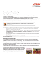
In order to insert the draw-out chassis into the fixed case carefully
align the guide rails on the draw-out chassis with the corners of the
fixed case. Then firmly and slowly push the handle on the front
fascia plate to insert the draw-out chassis into the fixed case. When
the chassis is almost fully inserted, an extra resistance will be felt
as the moving contacts on the draw-out chassis mate with the
25
contacts of the fixed case. At this point, press the handle very firmly to fully insert the draw-out chassis. Then
place the front cover by hooking the top catch over the clip on the fixed case. Align the front cover and refasten
the bottom catch by a quarter turn.
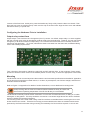
Configuring the Hardware Prior to Installation
Output relay contact form
Output relays 1 to 6 each have one changeover (form C) contact. As default, output relays 1 to 6 are supplied
with the normally open (relay de-energized) contacts wired to the terminal block. However, the user may easily
change any or all of the contacts of output relays 1 to 6 wired to the terminal block to be normally closed, as
required by the application. To do this, withdraw the draw-out chassis from the fixed case, as detailed taking
note of the handling requirements.
Then, referring to figure above, identify the relay N/O and N/C selection links, on the Analogue / Power supply
printed circuit board. Move the link to the desired position for each relay, to select the appropriate contact form.
Mounting
The RLC04-B can be mounted anywhere that meets the environmental specifications as detailed in Appendix 2,
and in particular it should be mounted indoors, in a clean, dry atmosphere, out of direct sunlight, and free from
excessive dust and vibration.
Refer to Figure 1 in Appendix 3 for details of outline dimensions, cut-out details and mounting holes.
Heat producing devices must be located at sufficient distances away to ensure that
the maximum operating temperature of the RLC04-B relay is not exceeded.
The RLC04-B is normally used as a flush mounted or 19 inch rack mounted instrument, for fitting on or within
switchgear or relay panels. The relay should be mounted at a convenient height above floor level to facilitate
optimum visibility and operator interaction.
The mounting holes of the fixed metal casing of the RLC04-B are accessible without removing the front cover
and/or the draw-out module. Therefore it is strongly recommended that the draw-out module should remain
protected by the fixed metal case during mounting and assembly of a RLC04-B into a panel or 19 inch rack.
26
Wiring
All current transformer, auxiliary voltage, output relay, digital input, and rear data port wiring connects to the
terminal block with 28 recessed terminals on the rear of the fixed casing. The terminals are clearly labelled.
Auxiliary power supply
Wire the auxiliary power supply to terminals 5 and 7.
The auxiliary power supply terminals can accept ac or dc input voltages and are not polarity sensitive.
Check carefully before energizing, that the auxiliary voltage falls within the range
indicated on the RLC04-B. Ensure that the auxiliary supply to the RLC04-B is
adequately protected by means of fuses or miniature circuit breakers to suit the fault
level and wire size used as well as the inrush current. High rupturing capacity fuses
(2A) are recommended.
Ensure that the power supply to the relay is capable of handling the necessary inrush current. This can be
estimated using the following equations:
DC supply: I = VDC / 10
AC supply: I = VAC / 20
Current transformer circuits
Connect the current transformer connections for elements 1, 2, 3 and 4 to terminals 21 & 22, 23 & 24, 25 & 26,
and 27 & 28 respectively.
One side of each CT circuit should be earthed, and multiple earth connections and
earth loops should be avoided.
Check carefully, before applying current transformer inputs, that the current transformer rated currents are
correct and correspond with the nominal rated currents of the relevant measuring elements
Refer to Table 5 in Appendix 1 for the acceptable current range, the short-time Over-current, and the VA burden
of the measuring elements.
Extremely hazardous voltages can appear across the CT secondaries if the CT
secondary current is open circuited. Do not attempt to connect, disconnect, service or
insert other devices in the CT secondary current loops without positively switching off
the primary circuit, and thus ensuring that the secondary current is zero.
Output Relay Circuits
Connect the output relay circuits to the terminals of output relays K1, K2, K3, K4, K5 and K6 to terminals 10 & 12,
14 & 16, 18 & 20, 13 & 15, 17 & 19 and 2& 4, respectively.
Check carefully before applying voltage to the output relay contacts that the loads and
voltages to be applied are within the ratings of the relay contacts. Refer to Appendix 1
for the continuous thermal rating, the short time current rating, the making/breaking
capacity, the maximum switching voltage and the maximum switching current of the
output relays.
Ensure that the voltages applied to the output relay contacts are adequately protected
by means of fuses or miniature circuit breakers to suit the fault-level, wire size and
contact rating.
27
Digital Input
If applicable, connect the digital input circuits to terminal numbers 9 and 11.
The digital input terminals can accept ac or dc input voltages and are not polarity sensitive.
Check carefully before applying voltage to the digital input terminals that the voltage
applied is correct and falls within the range detailed in Appendix 1.
Ensure that the voltage applied to the digital input is adequately protected by means of fuses or miniature circuit breakers to
suit the fault level and wire size used. High rupturing capacity fuses (2A) are recommended.
Serial Communication Port
If required, wire the Rx, Tx and common terminals (6, 8 & 3 respectively). Note that for RS232 a “crossover
connection” is required i.e. the Rx of the RLC04-B must be wired to the Tx of the host device and vice versa. For
RS485 models, the multi-drop wiring between RLC04-Bs and the wiring from the first RLC04-B to the host RS485
port, is Rx to Rx and Tx to Tx , i.e. not “crossed over”. For RS485 applications, to obtain the best results in
environments with high electrical noise, it is recommended that the last device in the line be terminated with a
120 resistor connected between terminal 6 (Rx-) and terminal 8 (Tx+) on the rear terminal block of the relay.
Earth Connection
It is recommended that a 4mm² earth conductor be installed from the RLC04-B earth terminal to the panel earth
bar. In addition, ensure that the panel is properly earthed in accordance with local regulations.
For personnel safety as well as not to adversely affect the RLC04-B by surges, transients
and other electrical and electro-magnetic disturbances, it is essential that the relay is
properly earthed as detailed above.
Noise Isolation
When properly connected and earthed, RLC04-Bs are highly tolerant of electrical and electro-magnetic noise.
Refer to Table 4 in Appendix 1 for the withstand ability. However, as with other microprocessor based
measurement and protection equipment, the RLC04-B must be installed, wired and located with some degree of
concern for electrical and electro-magnetic noise which could cause erratic operation. The relay should be wired,
mounted and isolated from sources of potential noise and disturbances in excess of those prescribed in Appendix
1.
In extreme cases this may require that filters or surge suppressors be applied to electro-magnetic devices
operating in close proximity to the RLC04-B.
To avoid possible problems from electrical and electro-magnetic noise and disturbances, or if specific problems
are experienced in this regard, obtain specialist advice regarding counter measures and solutions.
Performing any changes to element variable or other settings, changes to output relay
configurations, or running the diagnostic test sequence to test the output relays, may
cause the associated circuit breaker to trip. This could cause serious system disruption.
Therefore the greatest care should be exercised when performing these functions online, and the user should have a thorough knowledge of this entire manual as well as the
particular application and system.
28
Fully commissioning the relay involves programming it to the required configuration. It is necessary to read and
fully understand the following two sections with regard to this. Thereafter the complete step by step installation
and commissioning table in Appendix 1 can be referred to as a quick guide.
29
Navigating the RLC04-B Menu
1st Level Menus
When first switched on, and in its normal operating mode, the RLC04-B displays one of a selection of running
displays described in further detail in the section Operating the RLC04-B.
In order to set up the relay, to operate it in anything more than its most basic use, or to test the unit, it is
necessary enter the Menu Mode. Despite the number of programmable parameters, and the amount of
information that can be extracted from the relay, it is a relatively simple and intuitive process. It is achieved by
using just the five buttons on the front panel, the horizontal scrolling buttons W and X, the vertical scrolling
buttons S and T, and the red “accept” button .
When in menu mode, whether merely viewing information, or changing parameters, the
protection remains in operation and is not compromised in any way. The previous
parameters remain in force, until the “Save” action is activated, whereupon the changed
parameters come into force.
To enter the menu press both horizontal scroll buttons W and X simultaneously for five seconds.
If a unique password has not been defined, no password will be requested and the display will switch straight to
the Access PARAMETER SETUP menu screen in the main menu list.
If a password has been set, you will be requested to enter it. This is a 6
digit numeric code. For each digit scroll to the correct number using the S
or T buttons.
Move to the previous and next digits by using the W and X buttons
respectively.
The digit being addressed will be indicated by a cursor - a line beneath the
digit.
Once you have set all 6 digits correctly, press the red button to enter.
30
There are nine main menus available which can be scrolled through using W and X.
When shipped, the default password is 000000, which allows unrestricted access to all
menu functions. By setting a new password the valid password must be entered to
access to any interactive menu. This provides a measure of security against
inadvertent or unauthorized alterations to the relay settings. Unrestricted access is still
provided to the status and test functions, by pressing instead of entering the
password.
Some of these are used for programming the RLC04-B, and some for normal operation such as extraction of
information, and for testing:
st
nd
When viewing one of these 9 main 1 level menus, access the 2 level beneath it by pressing T. In the case of
nd
the Parameter Set-up option, the 2 level consists of a further series of menus. For the other options it will be a
series of parameter adjustment, information, or test screens depending upon the option.
2nd Level Menus
Once you have gone down to the 2nd level of the Parameter Set-up option, scroll through these menus using W
and X. Access them by pressing T. Return from the 2nd level menu list to the 1st level menus by pressing . An
exit process described below allows you to save or discard any adjustments made, or to return to make further
adjustments.
Changing or Selecting Parameters
After accessing a parameter adjustment level from the menu above it, the various screens, and the items within a
screen, are scrolled through using W and X. Parameters are adjusted or choices normally made by using S and
T.
When arriving at a parameter adjustment screen after pressing T from a menu above
it, take care not to keep T pushed in for too long or a parameter may be inadvertently
adjusted.
31
Some Exceptions
Some sub-menus do not follow the general rules described above.
Trip History
Scroll vertically to select a particular trip.
Scroll horizontally for information on a particular trip
Password Set-up
Scroll through screens using .
Scrolling
As described above, displays and parameters can be scrolled in either direction and values can be incremented
or decremented, by using the appropriate buttons. Generally X scrolls in the forward direction and W in the
reverse direction; S increments and T decrements a value or toggles an option. Holding a scroll button down
scrolls continuously. All scrollable sub-menus and parameters are of the “wraparound” type i.e. last wraps around
to first. When held down, the scroll speed gradually increases the longer the button is held.
Usually, once a parameter has been set to a value, or choice, the operator simply scrolls to the next item. All
items on a submenu are saved together in one operation. This occurs when exiting the sub-menu.
When programming the RLC04-B, it is important that any function that is not required
must be disabled, to prevent confusion and possible spurious operation. Disable is an
available option when scrolling a value, or selecting from possible choices.
The Exit Process
To revert to the next higher level menu press .
When exiting a screen from within the Diagnostic Test or Status Information options, or the 3rd level screens from
within the Parameter Set-up option, this is all that is needed.
To revert to the 1st level menu from other menus where parameters may have been adjusted, use S and T to
choose between the following options which are presented to you:
Re-enter the menu to make further changes
Save the changes made and exit the menu
Exit the menu without making any changes since the last save
Press
to have your choice accepted and conclude the exit process.
When “Save” is selected, there will be a short delay while the new parameters are
saved into the non-volatile memory.
To revert to the running displays from the 1st level menus, press both W and X simultaneously.
If the relay is inadvertently left in menu mode, it will automatically perform a “cancel”
operation and exit to the running displays after 10 minutes.
In the three sections of this manual that follow, the symbols W, X, S, T, or appearing at the beginning of a
line of text indicate that the relevant button should be pressed to change to the display to that which will be
described.
32
Programming the RLC04-B
Enter menu mode as described in the preceding section. Of the 9 first level menus the following 6 are used to
set-up the relay operating parameters. They all fall under the protection of the optional password. The first 4 setup menus are common to both Normal and H-Bridge Modes:
Hardware
Serial Ports
Password
Real-time Clock
The last two set-up menus offer different options which are mode dependent:
Parameters
Output Relays
Configuring the Hardware
The options here offer settings for the most fundamental operating configuring of the RLC04-B.
T Access the Hardware Setup selector 2nd level screens.
The first screen allows the relay to be set in Normal or H-Bridge mode by toggling the
options with S and T.
X Scrolling right allows the system frequency to be entered into the relay, toggling
between 50 and 60Hz with S and T.
X The next 4 screens allow the Element inputs 1 to 4 to be individually set for use with
current transformers with either 1A or 5A nominal secondary currents by toggling with S
and T.
X The final screen allows the RLC04-B response to be determined upon restoration of
power following an outage. The options of Clear trip state or Hold trip state are toggled
with S and T.
Exit using the standard - Resume/Save/Cancel - process.
Setting the Password
Setting a password is optional - Refer also to the Password Protection under Other
Facilities in Section 3 - Functional Description, and also Section 6 – Navigating the RLC04-B
Menu.
T Access the Password Setup 2nd level screens.
Enter the old password. Set each digit using S and T and scroll between digits using W
and X. If the password has not been previously defined, leave it at all zeros.
Progress to the next step.
Enter the new password by defining a 6 digit numeric code in a similar manner.
Exit using the standard
- Resume/Save/Cancel -
process.
Keep the password in a secure place. Losing the password will mean that access to
the protected functions will be denied, causing substantial inconvenience.
33
Serial Port Options
This function only needs to be set if either of the serial ports are to be used.
T Access the Serial Ports options 2nd level screens.
Choose the baud rate for the front port using S and T. Choose from the seven
rates between 2400 and 115200 using S and T. For a short distance connection
to a laptop computer the highest setting of 115200 is normally used.
X Scrolling to the right allows the setting of the parity to EVEN, ODD, or NONE,
using S or T.
X Scroll right to set the type of serial connection for the rear port. Choose
between RS232 and RS485 using S or T.
In some applications e.g. with some modems, in high electrical noise environments, or
long transmission distances, a lower rate may be required to achieve error-free
communication. Data transfers will naturally take longer at the lower rates, although
because the data is quite compact, this may not be noticeable.
X The next two displays allow the setting of the baudrate and parity for the rear port in the same way as for the
front port described above.
X Scrolling further to the right displays the applicable settings for the Modbus
communications protocol. Firstly is the address of the particular relay. Choose from
the values1 to 255 using S and T.
X Next is the Modbus response time. Choose from the range 0.01 to 10.00 seconds
using S and T.
X Set the Modbus dead time from the range 0.01 to 10.00s using S and T.
X Finally set the Modbus Force Relay Time from the range 0.1 to 60 seconds using
S and T.
Note that an understanding of the operation and requirements of Modbus RTU, as well
as the specific application, is required to decide on appropriate settings for these
parameters. If it is not intended to use Modbus in the applications, these settings can
be ignored.
Exit using the standard
- Resume/Save/Cancel -
process.
34
Setting the Real-time clock
T Access the Set Real-time clock 2nd level screens.
Adjust each of the three values of hours, minutes, and seconds using
S or T, and scroll between them using W and X.
X Scroll right to change to date. Adjust each of the four values of day of
the week, day, month, and year using S or T, and scroll between them
using W and X.
Exit using the standard
- Resume/Save/Cancel -
process.
Parameter Setup - Normal Mode
T Access the Parameter Set-up sub-menus.
Use W and X to scroll through the following 2nd level menus, before using T to access the 3rd level screens:
Set Element 1, 2, 3 Variables
Set the Icr/In (capacitor rated current–to-CT nominal current) ratio to a value within the
range 0.25 to 1.50 using W and X.
X Further scrolling to the right allows the setting of the other parameters for Elements 1 to 3 in the same way:
vc>al/vcr
Ith>:xt
I1>>:xt
vc>al:xt
Ith>>/In
I1</In
vc>/vcr
Ith>>:xt
I1<:xt
Revert to the 2nd level menus by pressing
ҏ
vc>>/vcr
Irms>/In
vc>>:xt
I1>/In
Irms>:xt
vc>reset
I1>:xt
Irms>>/In
Ith>/In
I1>>/In
Irms>>:xt
.
35
Set Element 4 Variables
In the same fashion as for Elements 1 to 3, the following Element 4 variables can be set:
Iub_al/In
Iub_al:xt
Revert to the 2nd level menus by pressing
Iub>/In
Iub>:xt
Iub>>/In
Iub>>:xt
.
Set Element 5 Variables
In the same fashion as for Elements 1 to 3, the following Element 5 variables can be set:
Io>/In
Ilub>/In
Revert to the 2nd level menus by pressing
Io>:xt
Ilub>:xt
Io>>/In
Ilub>>/In
Io>>:xt
Ilub>>:xt
.
Set Other Functions
Using S or T, select between Breaker-Bon, Remote Reset, Event Trip, or Disabled for
the Digital input function.
X Toggle between active high or low for the digital input using S or T.
X Select the Event:xt time-out value using S and T. This is only relevant if the digital
input function has been set to Event.
X Set the Bfail1:xt time-out value using S and T. If the Bfail1 function is not required,
set Bfail1:xt to N/A.
X Set the Bfail1 release condition using S and T. Select from Ifund<10%In, Dig-Input,
Ifund AND Input, or Ifund OR Input. The latter 3 conditions are only relevant if the
digital input function has been set to Breaker-Bon.
X Set the Bfail2:xt time-out value using S and T. This is only relevant if the digital
input function has been set to Breaker-Bon. If the Bfail2 function is not required, set
Bfail2:xt to N/A.
X Set the B ena:xt time-out value using S and T. This is only relevant if the digital
input function has been set to Breaker-Bon.
X Set the Bena trigger condition using S and T. Select from Ifund<10%In, Dig-Input,
Ifund AND Input, or Ifund OR Input. This is only relevant if the digital input function has
been set to Breaker-Bon.
X Using S or T, select between Only trip STARTS, Only ALARMS, STARTS and
ALARMS, or always off.
Revert to the 2nd level menus by pressing
.
36
Compensate for Star Unbalance
Compensation of the natural unbalance current can only be done after the relevant capacitor bank or filter circuit
is in service.
The display initially shows the magnitude and angle of the compensation vector. The
examples here show instances where the system is firstly uncompensated, and secondly a
typical screen for a compensated system.
X Scrolling right shows the calculated unbalance current, either in absolute terms if
uncompensated, or in relative terms, ǻIub, if compensated. To compensate the system
toggle the display to Yes with S or T and press .
After compensation, the compensation vector has the same magnitude as the initial measured fundamental
frequency unbalance current at the instant of compensation, but has the opposite polarity (i.e. is 180° out of
phase).
Immediately after compensation, ǻIub will always be the null vector.
However, after compensation any subsequent change in capacitance will cause. ǻIub to assume a non-zero
magnitude and some phase angle ranging from 0° to 360°. The magnitude of ǻIub is a measure of the change in
capacitance in any leg of the double star capacitor bank arrangement. The phase angle of ǻIub indicates the leg
in which the change in capacitance has occurred. Refer to figure 8 and 9 in Appendix 3 for further details on this.
X The next screen allows the user to clear the existing compensation from the system by
toggling the display to Yes with S or T and pressing . The display then reverts to the
previous screen.
Revert to the 2nd level menus by pressing
.
Clear Trip History
This consists of a single screen. Use S to toggle between Yes and No.
- Resume/Save/Cancel From any of the 2nd level menus, exit using the standard
process.
Output Relay Setup – Normal Mode
T Access the Output Relay set-up screens.
The first screen allows the user to allocate any combination of the 5 output relays to a
vc>alarm signal. The relay being addressed is denoted by the cursor. Use S or T to
toggle between 0 (de-allocated) and 1 (allocated). Scroll between relays and subsequent
screens using W and X
By scrolling to the right the output relays can be allocated to the following signals in the same way:
vc>start
Irms>start
I1<trip
vc>trip
Irms>trip
Iub_alarm
vc>>trip
Irms>>trip
Iub>start
I1>start
Ith>start
Iub>trip
I1>trip
Ith>trip
Iub>>trip
I1>>trip
Ith>>trip
Io>start
37
Io>trip
B fail 2
Io>>trip
B era
Ilub>start
Event_trip
Ilub>trip
Ilub>>trip
B fail 1
X The next screen allows the user to select for each relay whether it is normally
energised (1) or de-energised (0) in the healthy state.
X Select for each relay whether it latches upon a trip, and would subsequently need to
be reset, or whether it resets automatically after the fault causing the trip has cleared.
X The next 5 screens show the internally generated checksums for each relay.
Performing a manual calculation of these checksums and comparing the two, provides
a double check that the relays have been allocated correctly. See Appendix 2 for more
details on this.
Revert to the 1st menus using the standard
- Resume/Save/Cancel -
process.
Parameter Setup – H-Bridge Mode
T Access the Parameter Set-up 2nd level menus.
Use W and X to scroll through the following 2nd level menus, before using T to access the 3rd level screens:
Set Element 2, 3, 4 Variables
Set the alarm threshold within the allowed range using S and T
X Next adjust the time-out value associated with the alarm threshold.
Further scrolling right will allow the user to adjust the low-set and high-set thresholds with their associated timers
for aIub, as well as all of the similar settings for bIub and cIub.
Revert to the 2nd level menus by pressing .
38
Set Other Functions
Using S or T, select between Remote Reset, Event Trip, or Disabled for the Digital input
function.
X Toggle between active high or low for the digital input using S or T.
X Select the Event:xt time-out value S and T. This is only relevant if the digital input
function has been set to Event.
X Using S or T, select between Only trip STARTS, Only ALARMS, STARTS and
ALARMS, or always off.
Revert to the 2nd level menus by pressing
.
Compensation for xIub
The following description applies to the sub-menus Compensate for aIub, Compensate for bIub, and
Compensate for cIub, which are each compensated separately.
Compensation of the natural unbalance current can only be done after the relevant capacitor bank or filter circuit
is in service.
The display initially shows the magnitude and angle of the compensation vector. The
examples here show instances where the system is firstly uncompensated, and secondly a
typical screen for a compensated system.
X Scrolling right shows the calculated unbalance current, either in absolute terms if
uncompensated, or in relative terms, ǻIub, if compensated. To compensate the system
toggle the display to Yes with S or T and press .
After compensation, the compensation vector has the same magnitude as the initial measured fundamental
frequency unbalance current at the instant of compensation, but has the opposite polarity (i.e. is 180° out of
phase).
Immediately after compensation, the compensated current, ǻaIub, will always be the null vector.
However, after compensation any subsequent change in capacitance will cause .Iub to assume a non-zero
magnitude and some phase angle ranging from 0° to 360°. The magnitude of ǻaIub is a measure of the change
in capacitance in any leg of the double star capacitor bank arrangement. The phase angle of ǻaIub indicates the
leg in which the change in capacitance has occurred.
X The next screen allows the user to clear the existing compensation from the system by
toggling the display to Yes with S or T and pressing . The display then reverts to the
previous screen.
Revert to the 2nd level menus by pressing
.
Clear Trip History
This consists of a single screen. Use S to toggle between Yes and No.
- Resume/Save/Cancel From any of the 2nd level menus, exit using the standard
process.
39
Output Relay Set-up - H-Bridge Mode
T Access the Output Relay set-up screens.
The first screen allows the user to allocate any combination of the 5 output relays to an
aIub alarm signal. The relay being addressed is denoted by the cursor. Use S or T to
toggle between 0 (de-allocated) and 1 (allocated). Scroll between relays and subsequent
screens using W and X
By scrolling to the right the output relays can be allocated to the following signals in the same way:
aIub>start
bIub>>trip
aIub>trip
cIub_alarm
aIub>>trip
cIub>start
bIub_alarm
cIub>trip
bIub>start
cIub>>trip
bIub>trip
Event_trip
X The next screen allows the user to select for each relay whether it is normally
energised (1) or de-energised (0) in the healthy state.
X Select for each relay whether it latches upon a trip, and would subsequently need to
be reset, or whether it resets automatically after the fault causing the trip has cleared.
X The next 5 screens show the internally generated checksums for each relay.
Comparing these to manually calculated ones provides a double check that the relays
have been allocated correctly. See Appendix 2 for more details on this.
Revert to the 1st menus using the standard
- Resume/Save/Cancel -
process.
40
Operating the RLC04-B
The operation of the RLC04-B falls into three categories, Healthy condition, Fault (trip or alarm) condition, and
Information retrieval
Healthy Condition
The LED Indicators
In the healthy condition the green LED will be alight.
The Running Displays
After auxiliary power-up, and during normal operation, the LCD can display any of a number of screens showing
the instantaneous values of various measured and calculated parameters of the RLC04-B.
These are termed the Running Displays.
For each mode, Normal and H-Bridge, there are two sets of displays.
They are the standard set which are scrolled through using S and T, and the extended set which are scrolled
through using W and X. Each screen in one set has an associated screen in the other set, from which scrolling
starts when changing from one set to the other.
The associated screens are shown alongside each other in the full listings of available screens below.
So for example, if the Time & Date screen has been scrolled to using S or T, pressing W or X will bring up the
Digital Input detail screen. Further use of W or X will display the other screens in the extended set.
Most of the screens show values measured or calculated by the relay and are fairly self-explanatory.
<
The displays show small indicators for each of the protective function thresholds (alarm: al ; undercurrent: ; low>
set: ; high-set: >>) where they have been set.
This not only allows the user to see which protective functions are set, but furthermore if the function is active the
associated indicator starts to blink.
If the relay is not measuring a signal or if the signal is below the suppression level the display will only show --%.
In both Normal and H-Bridge modes the Reference phase screen shows the fundamental component of Element
1.
If the Reference phase current falls below 10% of the nominal current In, then this has an impact on the way the
star point and H-bridge unbalance protection functions operate – see Section 3 – Functional Description for
details.
Again applicable for both modes, the last screen in the extended set (adjacent to the Date and Time) shows the
state of the digital input. The text reflects the function of the input as follows:
Disabled
Breaker-Bon
Remote Reset
Event Trip
Digital Input OFF
Breaker Position (Open or Close)
Trip Reset State (No trip reset or Trip reset)
Free Text (Inactive text or Active text) which is
downloaded using the PC communication program.
41
Normal Mode Displays
The available displays in Normal Mode are shown in the table below. The three values shown in each of the first
four standard set screens are the instantaneous values for the Elements 1, 2 and 3. In the extended set, the
maximum value of the three parameters is shown, along with the low set threshold.
Standard (S / T)
Extended (W / X)
A typical screen display can look as follows:
The screen shows that the low set and high set trip thresholds have been set, but not the
alarm, and that the maximum of the capacitor voltage in the three elements is 103%.
If the value would exceed the low set threshold (110%) the low set trip indicator (>) would start to blink, while if
the value would exceed the high set threshold, both indicators (> and >>) would blink.
H-Bridge Displays
The available displays in H-Bridge Mode are shown in the table here:
Standard (S / T)
Extended (W / X)
A typical display for a compensated system (indicated by the ǻ) will look as follows:
The screen shows that the alarm, as well as the low set and high set trip thresholds have
been set, and that the actual unbalance current in the a-phase is 1%.
If the value would exceed the alarm threshold for the time set, the alarm indicator will start to blink. If the
unbalance current exceeds the low set threshold (10%), the low set trip indicator (>) would also start to blink,
while if the value would exceed the high set threshold, all three indicators (al and > and >>) would blink.
42
Default Display
Upon power up, or when in normal operation no scroll key has been pressed for one minute, the relay will revert
to the default display. Upon delivery, the default display for the relay in Normal Mode is the Element 1,2 and 3
repetitive peak capacitor voltage, vc screen, while for the H-Configuration mode the summary screen showing
the a-, b- and c-phase unbalance currents is the default display.
Any other of the standard or extended screens can be set as the default simply by pressing while that desired
screen is displayed. The relay will show a short message “New DEFAULT DISPLAY saved”.
Fault Condition
The LED Indicators
In a fault condition the green LED will extinguish and the yellow or red LED will light according to the level of
fault.
Yellow LED: START – Based on the selected setting of “Start LED shows:” in the “Set OTHER functions” menu
the following functionality will be achieved:
Only trip STARTS
Only ALARMS
STARTS + ALARMS
Always off
The Start LED lights on STARTS which will cause a subsequent trip; ALARMS are
ignored
The Start LED will flash on ALARMS; STARTS are ignored
The Start LED will flash for ALARMS and light up constantly on STARTS which will
cause a subsequent trip
The Start LED will never light.
Red LED: This indicates that a trip condition has occurred that has not yet been acknowledged. Only when all the
post trip fault annunciation screen displays have been acknowledged will this LED extinguish.
The Running Display
When one of the set threshold levels has been exceeded, but before a trip has been output, the normal operation
screen remains displayed. In addition the small indicators (al, <, >, or >>) on the display start to blink, to signal
the active function.
Post-trip Fault Annunciation Displays
Immediately that a trip occurs, the trip information is recorded in the Trip History list. The post-trip annunciation
displays described here are actually a sub-set of trip history.
They relate only to the latest trip, and are displayed for the operator’s convenience. The set of post-trip data
displayed indicates which software trip signals were generated for each trip event.
The magnitude of parameter causing the corresponding software trip signal at the instant of generation is
recorded, as well as the time taken from the moment the relevant trip threshold was exceeded, until the software
signal was generated. In case of protective functions which operate with values from Element 1, 2 and 3, the
post-trip display also shows the Element number in which the maximum or minimum of the parameter occurred
as well as the element(s) which have been above the threshold at the instant of trip.
In the case of the star-point and H-Bridge unbalance trip signals, the relevant phase angle of the unbalance
current is also recorded, to indicate in which leg of the capacitor bank, capacitor failure has occurred (Refer to
Figures 6 to 9 in Appendix 3).
43
Under normal circumstances, after a trip condition, an operator would assess and note the relevant information
from the post-trip annunciation screen, and then acknowledge (i.e. reset) the trip by pressing .
At this point, any other trip conditions that may have occurred after the first trip condition, will be displayed. Again
the user can acknowledge this indication, by pressing .
After all of the post-trip annunciation screens have been acknowledged, the display reverts to the normal default
operating screen.
After investigating and rectifying the fault condition, the operator would normally only then re-energize the tripped
circuit breaker. If, however, the tripped circuit breaker is re-energized before the post-trip screens have been
acknowledged, then the post-trip annunciation screens will continue to be displayed until they are acknowledged,
as previously detailed, after which the normal operation screen, will be displayed.
If a further fault condition were to occur, causing the circuit breaker to trip again, before the previous post-trip
screens have been acknowledged, then the previous fault trip data is replaced with the latest data.
It is only possible to acknowledge a trip once the fault has been cleared – the yellow
LED must be OFF, otherwise you will only be able to scroll through the post trip data.
Typical Post-Trip Annunciation Displays
Some typical examples of post-trip annunciation displays are shown below.
M3-12 means that Element 3 attained the maximum amplitude at the instant of trip, while elements 1 and 2 were
also above the threshold setting.
Information Retrieval
Trip History List
As mentioned above, immediately that a trip occurs, the trip information is recorded in the Trip History list. This
list records data for up to 25 trip events.
Trip events which happen during a so-called trip session are pooled together in one group, with No. 1 being the
most recent. It is saved in the non-volatile EEPROM memory and is therefore also available after loss of power
supply.
With the relay in normal operation, the complete TRIP HISTORY list is accessed by entering Menu Mode.
T Access the Browse TRIP HISTORY list 2nd level screens.
44
This is an example of the first screen which indicates how many trips are in memory.
W and X toggle between the first screen and this screen which shows
exactly the when the trip history list was last cleared.
When either of the two screens above are being displayed, it is possible to clear the complete trip history by
pressing . The following is displayed:
Use the S or T to toggle the “No” to “Yes”. Then press
to clear the Trip History list.
This is only possible if the correct password has been entered when accessing Menu Mode, or if no password
has been set. Alternatively the trip history can be cleared from within the Parameter Setup menu.
T Scrolling down from the Trip History screen, the display shows trip number screen.
This indicates the time and date of the 1st (N01) trip of the first trip session (G01).
X Scrolling right will reveal the details of the trip over three screens. The
first shows the cause of the trip and its magnitude, which elements were
affected, and the time it took to trip.
The second screen shows the relevant values for all three elements.
The third screen shows which relays were tripped.
X Scrolling right once more will return to the trip number screen
TScrolling down further will reveal all of the trip number screens in succession, from which the details can be
discovered using W and X.
When all of the desired TRIP HISTORY list data has been viewed, press to revert to the main menu.
Status Information
(Optional Password Protection – partially)
This menu allows the user to obtain certain information from the relay such as:
Installation information
Output relay status
Setup saved counter
Digital input function
Communication port activity
Protective function trip counters
Enter Menu Mode in the usual fashion.
T Access the STATUS INFORMATION 2nd level screens.
45
The first screen displays a moving message of maximum length 100 characters, which can
be downloaded from a PC running the dedicated communication software.
X This screen enables the user to check that the digital input is functional. When a voltage
is applied to the digital input terminals, the above display should change from Low to High.
X This screen enables the user to check if any of the output relays are energized.
X These two screens (Front / Rear) enable the user to check if the serial data ports are
functional. When data is received or transmitted, the respective part of the communication
display should change from OFF to ON.
X This screen allows user to check how many times the set-up has been saved on this
unit.
Additionally by pressing S or T the date of the last save of set-up
information can be accessed.
The screens which follow are operating mode dependant. They show the trip counters for the individual trip functions
together with the time stamp information when the counter has been last cleared.
Relay configured in Normal Mode
X This indicates that the vc>alarm signal has been generated 12 times since the last
clearance of the counter.
S or T toggle between the above screen and this which shows the date of the
last clearance of the counter.
X The next 20 screens will show the user similar information about the following trip functions:
vc>
Irms>
Iub>
Ilub>>
vc>>
Irms>>
Iub>>
Bfail 1
I1>
Ith>
Io>
Bfail 2
I1>>
Ith>>
Io>>
Bena
I1<
Iub_alarm
Ilub>
Event
Relay configured in H-Bridge Mode:
X This indicates that the aIub alarm signal has been generated 12 times since the last
clearance of the counter.
S or T toggle between the above screen and this which shows the date of
the last clearance of the counter.
X The next 9 screens will show the user similar information about the following trip functions:
aIub>
cIub_al
aIub>>
cIub>
bIub_al
cIub>>
bIub>
Event
bIub>>
Clearing the Counters
Any of these counters can be reset individually if the unit is not password protected, or if the password has been
entered correctly upon entry into the main menu.
46
In order to reset the individual counters perform the following steps:
Select the desired counter using W orX. Press the to select the counter.
The display changes as follows:
Use S or T to toggle between No and Yes, then press to clear the counter. The time
stamp information will be updated accordingly. If No is selected the relay will revert to the
Access STATUS INFORMATION menu.
47
Testing and Troubleshooting
Automatic Self-testing
On application of the auxiliary supply voltage, and at regular intervals in the background during normal operation,
the RLC04-B automatically performs a number of diagnostic checks of the:
o EEPROM
o Calibration factors
o EPROM
o RAM
o Processors
Any errors detected will cause the relay to suspend all protective functions, de-energize the self-supervision relay
and display an error message as detailed below:
Display Message
EPROM Error
EEPROM Error
RAM Error
DSP Stopped
Error Description
Firmware EPROM memory checksum discrepancy
Non-volatile EEPROM memory checksum discrepancy
Volatile RAM memory failure
DSP watchdog failure
User-performed Diagnostic Tests
During commissioning, while in normal service, or in the test laboratory, a series of diagnostic tests may be
performed by the user. These tests enable the user to check functionality, hardware, and certain information as
described below.
All protective functions are fully operational while performing these series of diagnostic tests, except during the
testing of the output relays!
T Access the DIAGNOSTIC TEST sequence 2nd level screens.
This enables the user to verify that the serial number embedded in the RLC04-B
corresponds with that engraved on the fascia plate
X The first 3 digits indicate the software version number. The next 3 double digit groups
refer to changes made, to either the User Interface, the Protection software module, or the
DSP code.
X If the user forgets the set password, this code must be included in an official written fax
request to Strike Technologies for them to provide to the user a password valid for a single
session.
X This shows the result of a series of factory tests made prior to dispatch. A screen
displaying anything different indicates a fault condition, and the relay should be returned to
Strike Technologies.
X This screen causes every pixel of the LCD display to operate, allowing the user to
identify any faults on the screen.
X This enables the user to check that the LED indicators work by checking that they flash
during this test.
X This enables the user to check that the digital input is functional. When a voltage within
the range 30 – 250 V ac/dc is applied to the digital input, the display should change from
LOW to HIGH.
48
Performing the following diagnostic test on the output relays, while the associated circuit
breaker is energized may cause the circuit breaker to trip, with consequent system
disruption. Therefore the greatest care should be exercised when performing this function
under live conditions.
X To perform the output relay tests, press S or T to toggle the “No” to “Yes”, then press
.
To skip this test press X to go to the next screen.
If Yes had been selected a screen as shown below will be displayed:
Press W or X to select the desired relay to test, then press S or T to toggle
the “No” to “Yes”, followed by . The selected output relay will then energize
for 1 second. Repeat for each relay.
Press W or X until this screen is displayed. Press S or T to toggle the “No”
to “Yes”, followed by . The first screen in the DIAGNOSTIC TEST MENU is
now displayed again.
If “No” is selected at the “Test Relays?” screen, pressing X displays:
X The next two screens supply hardware information which may be necessary in future to
ensure compatibility with firmware upgrades.
Press
to revert back to the main menu.
Injection Testing
The RLC04-B Relay is a complex device with many sophisticated protective functions. It is beyond the scope of
this manual to fully detail how too comprehensively injection test the RLC04-B. However the following points
should be noted.
Ideally, a 3 phase secondary injection test set, with the ability to inject not only mains frequency currents but also
complex 3 phase waveforms (including harmonic currents) is required to properly test the RLC04-B.
In this way one can properly test and confirm the peak repetitive overvoltage protective functions, the rms
thermal overcurrent protective functions, and the mains frequency current protective functions including the star
unbalance, line unbalance, earth fault, fundamental frequency over- and under-current, breaker fail and breaker
enable timer.
Such a test set is available from Strike Technologies.
It is possible to perform tests on the relay with only a single phase current injection test set. In this case the user
should preferably test each element separately, one protective function at a time, with all other protective
functions disabled.
If testing several protective functions and/or elements simultaneously, the following must be kept in mind:
The earth fault current Io is derived mathematically as the vector summation of the phase currents of elements 1,
2 and 3. Therefore the earth fault protective function should be tested by injecting 1/3 of the desired earth fault
current into elements 1, 2 and 3 connected in series. This will generally avoid the other protective functions,
including the line unbalance current protective function, from operating before the earth fault protective function.
In order to test the line unbalance current function, inject a low magnitude single phase current into elements 1
and 2 (or elements 2 and 3) connected in series but with opposite polarities. This will avoid the earth fault
protective function from operating.
In order to test the overcurrent, undercurrent and thermal current, protective functions of elements 1, 2 and 3,
disable the earth fault protective function and inject a single phase current into elements 1, 2 and 3 connected in
series. This will avoid both the earth fault and the line unbalance current protective functions from operating.
Alternatively disable both the earth fault and the line unbalance current protection functions. This will enable
elements 1, 2 and 3 to be tested individually, without all 3 elements connected in series.
49
Without the ability to inject harmonic currents superimposed onto the fundamental current, the repetitive peak
overvoltage protective function of element 1, 2 and 3 can be easily tested by disabling all other protective
functions, and injecting a sinusoidal current into element 1, 2 or 3. It is suggested that Icr/In = 1 and vc>/vcr = 1,1
should be set. In this case, when a sinusoidal current equal to In is injected (1A or 5A rms) then the calculated
peak repetitive voltage vc/vcr should be 1p.u. The vc>starter should operate for injected currents above 1,1In.
Trip times for currents above the threshold (1,1In) may be checked against the inverse time curve of Figure 3 in
Appendix 3.
Trouble Shooting
Before attempting to trouble-shoot the equipment, the user should thoroughly understand this entire manual, and
should have a prior knowledge of power system protection, power system measurements, and power system
safety procedures. The user should study carefully the applicable sections of this manual, taking particular note
of WARNINGS, CAUTIONS and NOTES included for personnel and equipment protection.
For trouble-shooting and commissioning, the following equipment is required:
Digital multimeter with clip-on current tong for measuring 1A or 5A current transformer secondary’s.
A three or single phase primary or secondary injection test set to enable injection of the CT nominal rated
secondary currents into the RLC04-B Relay measuring elements.
Due to the nature of the RLC04-B Relay, it is not recommended that the user should attempt repairs other than
the removal and replacement of the draw-out unit which houses all electrical and electronic parts.
If erroneous, inconsistent or nonsensical data is displayed on the RLC04-B, or if erratic faulty operation is
experienced by the user, check the various parameters set in the relay and verify that the relay is set up
correctly.
If the user has performed all the above checks, and is satisfied that no external or setting-up problems exist
which are causing the malfunctions experienced, then the relay should be returned to Strike Technologies
together with a fault report, documenting the details of the problem experienced, the configuration & set-up, as
well as installation details.
The user may elect to send only the draw-out unit without the fixed case. If so then special attention should be
paid to the handling requirements, as detailed in the Installation and Commissioning section.
50
Appendix 1
Table 1 - Step-By-Step Installation Instructions
1
2
3
4
5
6
7
8
9
10
11
12
13
14
15
16
17
18
19
20
21
22
23
24
25
26
27
Unpack the relay, and check for obvious damage.
If the contact form (normally open or normally closed) of any of output relays #1, #2, #3, #4, #5 or #6 is to
be changed from the default settings of normally open to normally closed, withdraw the draw-out module
and reconfigure the appropriate contacts.
Insert the draw-out module back into the fixed casing and affix the front cover of the relay.
Mount the RLC04-B Relay within a cut-out on the switchgear or relay panel, or within an appropriate 19
inch rack. Ensure that the fixed housing is securely screwed to the panel or 19 inch rack, using the
mounting holes on the fixed housing. These are accessible from the front without removing the front cover
of the relay.
Wire the auxiliary power supply to the relay - do not apply voltage yet.
Wire the current transformer circuits to the relay - do not apply current to the inputs yet.
Wire the appropriate output relay circuits to suit the application - do not apply voltage yet.
If applicable, wire the digital input circuits - do not apply voltage yet.
Measure the auxiliary power supply voltage, the voltages for the output relays and the voltage for the digital
input. Confirm that these voltages are correct and within the acceptable range in accordance with the
RLC04-B specifications. Only then apply these voltages to the relay. Measure the voltages at the terminals
to confirm that the voltages at the relay terminals are correct. Check that with auxiliary power applied, the
self-supervision relay #6 is energized and that its contacts are in the correct state.
Check that the LCD screen is showing the normal operation display, that the green POWER ON /
HEALTHY LED is on, and that the yellow and red LED’s are off.
Access the main menu. See Section 6 – Navigating the RLC04-B Menu for details.
Access the Hardware Setup Menu and configure the relay to suit your application (Normal Mode / H-Bridge
Mode \\ 50Hz / 60Hz \\ Element 1-4 rated current selection).
Configure the parameter settings for the protection elements as well as the OTHER settings to suit the
application.
Save the parameter settings configured.
From the main menu, access the OUTPUT RELAY SETUP function.
Configure the functionality of output relays 1,2,3,4, and 5 to suit the application.
Check that the output relay checksums are correct for the desired output relay configuration.
Save the output relay functionality configuration.
From the main menu, access the DIAGNOSTIC TEST sequence, and execute the diagnostic test. Confirm
that all diagnostic tests produce satisfactory results.
From the main menu, access the SERIAL PORT options, and select the appropriate baud rate and parity
(and type of backside port) for the serial ports.
Save the serial data port settings.
From the main menu, access the ACCESS AND SET REAL TIME CLOCK to the actual time and date.
Revert back to the normal running screen displays.
Perform primary or secondary injection tests. Confirm that the normal running parameters displayed are
correct, and that the protective functions are operational. Perform any other relevant commissioning checks
and tests.
Once any other commissioning tests associated with the complete installation are completed, and the
associated circuit breaker is energized, check that the parameters displayed on the normal running screen
are sensible and correct.
Compensate either the natural star point unbalance current, or the individual natural unbalance currents of
the H-Bridge if appropriate.
Document all the commissioning tests and the RLC04-B Relay settings carefully.
T Performing any changes to element variable or other settings, changes to output
relay configurations, or running the diagnostic test sequence to test the output relays
may cause the associated circuit breaker to trip. This could cause serious system
functions on-line, and the user should have a thorough knowledge of this entire
manual as well as the particular application and system.
51
Table 2:
Symbol
Icr
In
Icr/In
vc
vcr
vc>al
vc>al:xt
vc>alarm
vc>
vc>start
vc>trip
vc>reset
vc>>
vc>>:xt
vc>>trip
Irms
Irms>
Irms>:xt
Irms>start
Irms>trip
Irms>>
Irms>>:xt
Irms>>trip
W
Ith
Ith>al
Ith>alarm
Ith>
Ith>:xt
Ith>start
Ith>trip
Ith>>
Ith>>:xt
Ith>>trip
I1
I1<
I1<:xt
I1<trip
I1>
I1>:xt
I1>start
I1>trip
I1>>
I1>>:xt
I1>> trip
Iub
'Iub
Iub_al
Nomenclature and Definitions for Normal Mode
Definition
Capacitor rated current.
Current transformer nominal primary current
Capacitor rated current per unit of current transformer nominal primary current
Calculated capacitor repetitive peak voltage
Capacitor rated repetitive peak voltage
vc alarm threshold
Alarm time-out setting for the vc timer
Software signal indicating that vc has exceed vc>al for the time vc>al:xt set
vc low-set overvoltage threshold.
Software signal indicating that vc has exceeded vc>, and that the inverse timer is running
Software signal indicating that vc has exceeded vc> and the inverse timer has timed out
Time-out setting for the vc>/vcr reset timer
vc high-set overvoltage threshold
High-set time-out setting for the vc timer
Software signal indicating that vc has exceeded vc>> for the time vc>>:xt set
The calculated rms heating current
Irms low-set overcurrent threshold
Low-set time-out setting for the Irms timer
Software signal indicating that Irms has exceeded Irms>, and that the Irms timer is running
Software signal indicating that Irms has exceeded Irms> for the time Irms>:xt set
Irms high-set overcurrent threshold
High-set time-out setting for the Irms timer
Software signal indicating that Irms has exceeded Irms>> for the time Irms>>:xt set
Heating / cooling time constant
Calculated thermal current response to Irms
Ith alarm threshold
Software signal indicating that Ith has exceeded the alarm threshold
Ith low-set overcurrent threshold
Low-set time-out setting for Ith timer
Software signal indicating that Irms has exceeded Ith> threshold
Software signal indicating that Ith has exceeded Ith> for the time Ith>:xt set
Ith high-set overcurrent threshold
High-set time-out setting for Ith timer
Software signal indicating that Ith has exceeded Ith>> for the time Ith>>:xt set
Calculated fundamental frequency current
I1 undercurrent threshold
Undercurrent time-out setting for the I1 timer
Software signal indicating that I1 has dropped below I1< for the time I1<:xt set, while the digital input was in the
Active state
I1 low-set overcurrent threshold
Low-set time-out setting for the I1 timer
Software signal indicating that I1 has exceeded I1> , and that the I1 timer is running
Software signal indicating that I1 has exceeded I1> for the time I1>:xt set
I1 high-set overcurrent threshold
High-set time-out setting for the I1 timer
Software signal indicating that I1 has exceeded I1>> for the time I1>>:xt set
Calculated uncompensated fundamental frequency star point unbalance current
Compensated fundamental frequency rms star point unbalance current, i.e. the change in fundamental frequency
rms current from that at the instant of compensation
Iub alarm current threshold
52
Alarm time-out setting for Iub
Software signal indicating that Iub has exceeded Iub_al for the time Iub_al:xt set
Iub low-set overcurrent threshold
Low-set time-out setting for the Iub timer
Software signal indicating that (')Iub has exceeded Iub> and the Iub timer is running
Software signal indicating that (')Iub has exceeded Iub> for the time Iub>:xt set
Iub high-set overcurrent threshold
High-set time-out setting for the Iub timer
Software signal indicating that (')Iub has exceeded Iub>> for the time Iub>>:xt set
Calculated fundamental frequency line unbalance current
Ilub low-set overcurrent threshold
Low-set time-out setting for the Ilub timer
Software signal indicating that Ilub has exceeded Ilub>, and that the Ilub timer is running
Software signal indicating that Ilub has exceeded Ilub> for the time Ilub>:xt set
Ilub high-set overcurrent threshold
High-set time-out setting for the Ilub timer
Software signal indicating that Ilub has exceeded Ilub>> for the time Ilub>>:xt set
Calculated fundamental frequency earth fault current
Io low-set overcurrent threshold
Low-set time-out setting for the Io timer
Software signal indicating that Io has exceeded Io>, and that the Io timer is running
Software signal indicating that Io has exceeded Io> for the time Io>:xt set
Io high-set overcurrent threshold
High-set time-out setting for the Io timer
Software signal indicating that Io has exceeded Io>> for the time Io>>:xt set
Input signal indicating that the circuit breaker of the capacitor bank / harmonic filter circuit is on
Signal indicating that when a trip occurred, the Bfail1 release function had not been fulfilled within the Bfail1:xt
Bfail1
time, indicating a failure of the circuit breaker to open
The function which stops the Bfail1 timer, selectable from: Ifund<10%In; Dig-Input (logic “1“ to “0“); Ifund AND
Bfail1
release
Input; Ifund OR Input
Bfail1:xt
Time-out setting associated with Bfail1 logic
Software signal indicating that the fundamental frequency current remained above the undercurrent threshold for
Bfail2
the Bfail2:xt time, while the digital input (Breaker-Bon) signalled a switching off (logic “1“ to “0“) - indicating the
failure of the circuit breaker to interrupt the capacitor bank / harmonic filter circuit current.
Bfail2:xt
Time-out setting associated with Bfail2 logic
Software signal that can be used to inhibit the re-energizing of the banks’ circuit breaker for a definite time after
the Bena trigger signal has become active. Bena output signal (Breaker inhibit) is normally at logic “0“ (low) and
Bena
goes to logic “1“ (high) when the bank is switched off, and reverts to logic “0“ (low) the definite time Bena:xt
thereafter.
Bena:xt
Timer setting associated with the Bena logic
A trip session starts from the first active trip condition until the last trip condition has been cleared. The visible
observation of this session is defined by the time when the trip LED lights up to the time when the alarm LED
may be used to
Trip session goes off. During this time S or T may be used to scroll between the different trip messages.
acknowledge trips for which the cause of the trip has fallen below the trip threshold. In case of an Ith trip, the trip
can be acknowledged as soon as the Irms has fallen below the Ith trip threshold, however the trip output function
will only be reset once Ith has fallen below the Ith trip threshold
Iub_al:xt
Iub_alarm
Iub>
Iub>:xt
Iub>start
Iub>trip
Iub>>
Iub>>:xt
Iub>>trip
Ilub
Ilub>
Ilub>:xt
Ilub>start
Ilub>trip
Ilub>>
Ilub>>:xt
Ilub>>trip
Io
Io>
Io>:xt
Io>start
Io>trip
Io>>
Io>>:xt
Io>>trip
Bon
53
Table 3: Nomenclature & Definitions for H-Bridge Mode
Symbol
Definition
1/2/3/4
In
a/b/cIub
a/b/cIub_al/In
a/b/cIub_al:xt
a/b/cIub_alarm
a/b/cIub>/In
a/b/cIub>:xt
a/b/cIub>start
a/b/cIub>trip
a/b/cIub>>/In
a/b/cIub>>:xt
a/b/cIub>>trip
¨a/b/cIub
Element 1/2/3/4
Current transformer nominal primary current.
Calculated uncompensated fundamental frequency a/b/c-phase unbalance current
a/b/cIub alarm threshold per unit of In
Alarm time-out setting for the a/b/cIub timer
Software signal indicating that a/b/cIub has exceeded a/b/cIub_al for the time a/b/cIub_al:xt set
a/b/cIub low-set threshold per unit of In
Low-set time-out setting for the a/b/cIub timer
Software signal indicating that ( ¨)a/b/cIub has exceeded a/b/cIub>, and that the a/b/cIub timer is running
Software signal indicating that ( ¨)a/b/cIub has exceeded a/b/cIub> for the time a/b/cIub>:xt set
a/b/cIub high-set threshold per unit of In
High-set time-out setting for the a/b/cIub timer
Software signal indicating that ( ¨)a/b/cIub has exceeded a/b/cIub>> for the time a/b/cIub>>:xt set
Compensated fundamental frequency rms a/b/c -phase unbalance current, i.e. the change in fundamental
frequency rms current from that at the instant of compensation
54
Table 4: General Characteristics
Applicable standard
IEC 60255
Operating temperature
-10 to +55 °C to IEC 60068-2-2
Storage temperature range
-20 to +70 °C to IEC 60068-2-2
Humidity
4 days, 95% RH, with temperature cycled between +25°C and + 45°C, to IEC 60068-2-3
Enclosure degree of protection
IP50 to IEC 600529
Shock: 15g, 3 pulses per direction, per axis. (total 18 times).
Shock and bump
Bump: 10g, 1000 pulses per direction, per axis (total 6000 times).
Vibration
9, 8ms-² (1g) constant frequency from 10 to 500 Hz per axis. To IEC 60255-21-1
To IEC 60255-21-2
2 kV rms 50 Hz for 1 minute, from all terminals to case (earth), and between terminals of
independent circuits.
Power frequency voltage withstand
1.5 kV rms across open contacts of output relays.
To IEC 60255-5
Impulse voltage withstand
5 kV peak, 1.2/50 µs waveshape, 0.5 J energy content, 10 shots in each polarity, between all
terminals and case (earth), and between terminals of independent circuits.
Insulation resistance
50 M minimum at 500 V dc, to IEC 60255-5
To IEC 60255-5
Immunity to high frequency disturbances
(1MHz burst disturbance test)
2.5 kV peak between independent circuits, and to case (earth).
1 kV peak across terminals of the same circuit.
To IEC 60255-22-1
Immunity to electrostatic discharges
(Electrostatic discharge test)
8 kV discharge in air with cover in place.
4 kV point contact discharge with cover removed.
To IEC 60255-22-2 and EN 50082-2
Immunity to fast transient bursts (Fast
transient burst test)
Immunity to high frequency electromagnetic
fields
Class 4 (4 kV). To IEC 60255-22-4 and EN 50082-2
10 V / m from 27 to 500MHz, to IEC 60255-22-3
10 V, 80% AM, from 150 to 80 MHz as well as
10 V / m, 80% AM, from 80 to 1000 MHz, to EN 50082-2
Conducted disturbances induced by radiofrequency fields immunity test
To EN 50081
Immunity to high frequency electromagnetic
field (Pulse modulated, simulation of the
effect of cell phones)
To ENV 50204
Conducted emissions
To EN 50081-2, from 150 kHz to 30 MHz.
Radiated emissions
To EN 50081-2, from 30 kHz to 1000 MHz.
Nett Mass
3 kg
Overall dimensions
103(w) x 177(h) x 248(d)
The power supply inputs of the RLC04-B are protected by MOV´s. Therefore it is not
possible to perform the power frequency and the impulse voltage withstand test on
these terminals on the commercial unit without causing damage!
55
Table 5: Technical Specifications
Measuring elements
Auxiliary power supply
Output relays
Quantity
Nominal rated current, In
Continuous current
Short time current
Burden
Accuracy of measurement
Nominal rated voltage, Vx
Operative range AC / DC
Burden with dc supply
Burden with ac supply
4
1A or 5A selectable in the software
15A
300A for 1s
<40m
+/- 2% of nominal rated current
30 – 250V ac/dc
40 - 250V AC / 30 - 300V DC
<14W with all relays and back-light ON
<24VA with all relays and back-light ON
Quantity
Alarm/trip relays: 5
Self-supervision relay: 1
1 changeover contact (form C), user configurable as
N/O or N/C
Resistive load:
Inductive load:
(cos ij = 1)
(cos ij = 0,4 L/R = 7 ms)
3,5A at 250 VAC:
5A at 250 VAC:
0,8A at 220 VDC
1A at 220 VDC
2A at 110 VDC
3A at 110 VDC
4A at 48 VDC
5A at 48 VDC
380VAC, 250 VDC
5A at 250 VAC:
3,5A at 250 VAC:
5A at 30 VDC
2,5A at 30 VDC
5A
380VAC, 125 VDC
100mA at 5 VDC
1
Breaker on; Remote reset; Event trip
Optically isolated
30 – 250V ac/dc voltage input
W, X, S, T, and
(Accept)
Miniature spring loaded manual pushbuttons
Back-lit Liquid Crystal Display (LCD), with full alphanumeric character set
16 character x 2 line
4mm
Light Emitting Diodes (LED's)
Green : POWER ON / HEALTHY
Yellow : START
Red : TRIP
2
Optically isolated
RS232 via DB9 socket
RS232 or RS485 – selectable in the software
2.4 - to 115.2 for each port separately selectable
Date; Weekday; hh:mm:ss
+/- 30s per month
Supercap (>14 days without power)
Contact form (per relay)
Load
K1
Rated load
K2, K3, K4, K5, K6
Max. operating voltage
Rated load
Digital input channel
Pushbuttons
Display
Indicators
Serial data ports
Real Time Clock
Rated carry current
Max. operating voltage
Min. permissible load
Quantity
Function
Isolation
Type
Function
Type
Type
Screen Size
Character height
Type
Function
Quantity
Isolation
Front port type
Rear port type
Baudrate (kBd)
Functionality
Accuracy
Backup
56
Table 6: Settable Parameters and Ranges – Normal Mode
Parameter
Icr/In
vc>al/vcr
vc>al:xt
vc>/vcr
vc>>/vcr
vc>>:xt
vc>reset:xt
Ith>/In
Ith>:xt
Ith>>/In
Ith>>:xt
IJ
I1>/In
I1>:xt
I1>>/In
I1>>:xt
I1</In
I1<:xt
Irms>/In
Irms>:xt
Irms>>/In
Irms>>:xt
Iub_al/In
Iub_al:xt
Iub>/In
Iub>:xt
Iub>>/In
Iub>>:xt
Io>/In
Io>:xt
Io>>/In
Io>>:xt
Ilub>/In
Ilub>:xt
Ilub>>/In
Ilub>>:xt
Function of Digital
Input
Event:xt
Bfail1:xt
Bfail1 released:
Bfail2:xt
Bena:xt
Bena trigger by:
Start LED shows:
Setting Range
0,25 to 1,50
0,80 to 1,50 // N/A
0,1 to 3600 s
0,80 to 1,50 // N/A
0,80 to 10,0 // N/A
0,03 to 10,0 s
1 s to 3600 s
0,25 to 1,50 // N/A
0 to 600 s // Alarm
0,25 to 1,50 // N/A
0 to 60 s
0,5 to 7200 s
0,25 to 1,50 // N/A
0,1 to 1200 s
0,2 to 10,0 // N/A
0,05 to 10,0 s
0,05 to 1,00 // N/A
0,1 to 10,0 s
0,25 to 1,50 // N/A
0,1 to 1200 s
0,2 to 10,0 // N/A
0,03 to 10,0 s
0,01 to 2,00 // N/A
0,1 to 600 s
0,01 to 2,00 // N/A
0,1 s to 14400 s
0,01 to 2,00 // N/A
0,05 to 60 s
0,05 to 1,00 // N/A
0,1 to 60 s
0,05 to 10,0 // N/A
0,05 to 10,0 s
0,01 to 1,00 // N/A
0,1 to 60 s
0,01 to 1,00 // N/A
0,05 to 10,0 s
Breaker-Bon // Remote Reset // Event Trip // Disabled
Resolution
0,01
0,01
0,1 s
0,01
0,01
0,01 s
1s
0,01
0,01s
0,01
0,01 s
0,1 s
0,01
0,1 s
0,1
0,01 s
0,01
0,1 s
0,01
0,1 s
0,1
0,01s
0,01
0,1s
0,01
0,1 s
0,01
0,01 s
0,01
0,01 s
0,01
0,01 s
0,01
0,1 s
0,01
0,01 s
Preset Value
1.00
N/A
0,1 s
N/A
N/A
0,03 s
1s
N/A
0,0 s
N/A
0,0 s
0,5 s
N/A
0,1 s
N/A
0,05 s
N/A
0,1 s
N/A
0,1 s
N/A
0,03 s
N/A
0,1 s
N/A
0,1 s
N/A
0,05 s
N/A
0,1 s
N/A
0,05 s
N/A
0,1 s
N/A
0,05 s
Disabled
0,03 to 600 s
0,01 to 2,0 s // N/A
Ifund<10%In // Dig-Input // Ifund AND Input // Ifund OR
Input
0,01 to 2,0 s // N/A
1 to 1200 s // N/A
Ifund<10%In // Dig-Input // Ifund AND Input // Ifund OR
Input
Only trip STARTS // Only ALARMS // STARTS +
ALARMS // Always off
0,01 s
0,01 s
0,03 s
N/A
Ifund<10%In
0,01 s
1s
N/A
N/A
Ifund<10%In
STARTS +
ALARMS
57
Table 7 – Settable Parameters and Ranges – H-Bridge Mode
Parameter
Setting Range
Resolution
Preset Values
aIub_al/In
0,01 to 2,00 // N/A
0,01
N/A
aIub_al:xt
0,1 to 600 s
0,1 s
0,1 s
aIub>/In
0,01 to 2,00 // N/A
0,01
N/A
aIub>:xt
1 s to 240 min
1s
1s
aIub>>/In
0,05 to 2,00 // N/A
0,01
N/A
aIub>>:xt
0,0 to 60 s
0,1 s
0,1 s
bIub_al/In
0,01 to 2,00 // N/A
0,01
0,01
bIub_al:xt
0,1 to 600 s
0,1 s
0,1 s
bIub>/In
0,01 to 2,00 // N/A
0,01
0,01
bIub>:xt
1 s to 240 min
1s
1s
bIub>>/In
0,05 to 2,00 // N/A
0,01
0,01
bIub>>:xt
0,0 to 60 s
0,1 s
0,1 s
cIub_al/In
0,01 to 2,00 // N/A
0,01
N/A
cIub_al:xt
0,1 to 600 s
0,1 s
0,1 s
cIub>/In
0,01 to 2,00 // N/A
0,01
N/A
cIub>:xt
1 s to 240 min
1s
1s
cIub>>/In
0,05 to 2,00 // N/A
0,01
N/A
0,1 s
cIub>>:xt
0,0 to 60 s
Function of Digital
Input
Remote Reset // Event Trip // Disabled
Event:xt
0,03 to 600 s
Start LED shows:
Only trip STARTS // Only ALARMS //
STARTS + ALARMS // Always off
0,1 s
Disabled
0,01 s
0,03 s
STARTS +
ALARMS
58
Appendix 2
Example 1: Calculation of Checksums for Output Relays 1 To 5
During an unhealthy system condition the RLC04-B can generate any of a number of software signals, each of
which can be allocated to one or more output relays. For each function routed to a relay, the relative bit in the
checksum table below must be set to a binary 1, for each function not routed to a relay the bit must be cleared to
0.
This results in a 30 digit binary code, for each output relay in Normal Mode, which is difficult for the user to
interpret. By representing this string in hexadecimal code (hex code), where up to four binary digits are converted
to one hex digit, the above binary string is converted to a unique 8 digit hex code, representing all the allocations
to that output relay. The four digits represent the decimal values 8,4, 2 and 1.
Example: Binary 1010 = (1 * 8) + (0 * 4) + (1 * 2) + (0 * 1) = 10 Decimal = A Hex
The result can be decimal values between 0 and 15. As the hex digit must be a single digit, the characters A...F
are used to represent the decimal values 10...15, as shown here:
Dec.
Hex
Binary
Dec.
Hex
Binary
Dec.
Hex
Binary
Dec.
Hex
Binary
15
14
14
12
F
E
D
C
1111
1110
1101
1100
11
10
9
8
B
A
9
8
1011
1010
1001
1000
7
6
5
4
7
6
5
4
0111
0110
0101
0100
3
2
1
0
3
2
1
0
0011
0010
0001
0000
Typical Examples of Output Relay Settings and Resulting Checksums
One of 5 Output Relays in Normal Mode Operation
2
2
D
4
A
0
1
3
Checksum
MSB
LS B
vc>trip
vc>>trip
I1>start
I1>trip
I1>>trip
Irms>start
Irms>trip
Irms>>trip
Ith>start
Ith>trip
Ith>>trip
I1<trip
1
0
0
0
0
0
0
0
0
1
0
0
1
1
Energize
vc>start
0
Latch
vc>alarm
1
Event_trip
0
Bena
0
Bfail2
1
Bfail1
0
Ilub>>trip
0
Ilub>trip
1
Ilub>start
1
Io>>trip
1
Io>trip
0
Io>start
1
Iub>>trip
0
Iub>trip
0
Iub>start
0
Iub_alarm
1
One of 5 Output Relays in H-Bridge Mode
0
0
0
6
2
2
Checksum Hexcode
3
MSB
LSB
1
1
0
0
0
1
0
0
0
1
0
0
0
1
1
aIub_alarm
aIub>start
aIub>trip
aIub>>trip
bIub_alarm
bIub>start
bIub>trip
bIub>>trip
cIub_alarm
cIub>start
cIub>trip
cIub>>trip
Event_trip
Energize
Latch
59
Example 2: RLC04-B Setting Calculations
20 Mvar harmonic filter with a double star capacitor bank
System
Earthing
Switch
Line CT’s
Cable
Filter
Filter reactors
33 kV + 5%, 3 phase, 50 Hz, 20 kA fault level
Solidly earthed
630 A SF6 circuit breaker
500 / 5 A
185 mm² XLPE
Output at 33 kV 50 Hz:
20 Mvar (lead)
Inductance:
20,6 mH per phase
Rated Currents
I1
I2
I3
I4
385A
30A
90A
25A
I5
I7
I11
I13
30 A
20 A
10 A
5A
¦ ( In )
2
x
630A
500A / 5A
20.6m H
400Ars s
13
Irms
3 3 kV / 5 0Hz
= 400A
37.19 MVAr
a t 45kV
n 1
Double star configuration
Rated output: 37.193 Mvar
Rated voltage and frequency: 45 kV 50 Hz
Rated current Icr = 37.193 10 /(
6
Capacitor bank
Unbalance CT
3 45000)= 477A
I1 at 33 kV = 20 10 /( 3 33000)
= 350A
Star point unbalance alarm current: 4 A – 3 s
Star point unbalance low set trip current: 8 A – 10 min
Star point unbalance high set trip current: 12 A - 1s
20 / 1 A
6
60
Settings
Bena:xt
Element 1, 2, 3 variables
=
600 s
(18)
Breaker-Bon
(19)
Dig Input
(20)
vc>/vcr
=
1,1
(2)
Function selected for
digital input:
vc>>/vcr
=
3,0
(3)
Bena triggered by
vc>>:xt
=
0s
(4)
Element 4 variables
vc>reset:xt
=
30 s
(5)
Iub_al/In
=
4/20=0,2
(21)
Ith>/In
=
395/500=0,79
(6)
Iub_al:xt
=
3
(22)
(23)
Icr/In
=
477/500=0,95
(1)
Ith>:xt
=
N/A
(7)
Iub>/In
=
8/20=0,4
Ith>>/In
=
410/500 = 0,82
(8)
Iub>:xt
=
10 min
(24)
Ith>>:xt
=
0s
(9)
Iub>>/In
=
12/20=0,6
(25)
=
1s
(26)
t
=
1200 s
(10)
Iub>>:xt
I1>/In
=
1,075·350/500=0,81
(11)
Element 5 variables
I1>:xt
=
600 s
(12)
Io>/In
=
0,2·350/500=0,14
(27)
I1>>/In
=
1,5·350/500=1,05
(13)
Io>:xt
=
0,1 s
(28)
I1>>:xt
=
0s
(14)
Io>>/In
=
N/A
(29)
I1</In
=
0,2·350/500=0,14
(15)
Io>>:xt
=
0s
(30)
I1<:xt
=
0,2 s
(16)
Other variables
Ilub>/In
=
0,05·350/500=0,04
(31)
Ilub>:xt
=
2s
(32)
Bfail1:xt
=
0,2 s
(17)
Ilub>>/In
=
0,1·350/500=0,07
(33)
Bfail2:xt
=
0,1 s
(17)
Ilub>>:xt
=
0,2 s
(34)
Notes on Settings
1. Capacitor rated current in p.u. of line CT primary current.
2. Capacitors made to IEC can withstand 110% of rated voltage for extended periods of time.
3. With reference to Figure 3 in Appendix 3, it can be seen that for vc/vcr greater than 3,0 the peak repetitive
overvoltage withstand curve is undefined and therefore for capacitor overvoltages above this value it is
considered necessary to trip with a definite time delay.
4. The time delay should be set as low as possible, preferably with no intentional delay.
5. Refer to the figure under Programmable vc>reset Timer in the Functional Description section to see the
effect of vc>reset:xt.
6. The low set thermal trip threshold is set in this case slightly below the continuous current rating, as it is
assumed that the total current includes some safety margins.
7. The associated timer is set to N/A (disabled) which means that only the Ith>start signal will be generated in
case of an overload and no subsequent trip signal Ith>trip is output.
8. The high set thermal overcurrent threshold is set slightly above the max. continuous rms current rating of the
reactor. If this is exceeded the bank must be disconnected.
9. The associated definite time delay is set to 0 (no intentional delay).
61
10. Refer to Example 3 in Appendix 2 for some guidance of the heating/cooling time constant of air-core filter
reactors. The time constant is the time taken for the reactors to reach 63% of their final temperature, for a
step change in current from 0 to 100%.
11. For a system having a maximum system voltage of 105% of nominal, a low set fundamental frequency
overvoltage/overcurrent limit of 107,5% is considered appropriate. Above this value the associated definite
timer will start timing out.
12. A value of 600s for this definite timer is considered appropriate to allow any automatic tap-changers to
operate in the case of extended fundamental frequency system overvoltages (which in time causes
fundamental frequency overcurrents in the capacitor/filter circuit).
13. A fundamental frequency overcurrent above 150% of nominal would indicate a catastrophic failure of some
kind requiring immediate tripping.
14. Therefore the associated definite time delay is set to 0 (no intentional delay).
15. Any undercurrent threshold significantly below nominal current is appropriate.
16. The undercurrent definite timer is set as 0,2s or any appropriate low value to avoid spurious trip outs.
17. The breaker fail timer is set as 0,2s for Bfail1 and 0,1s for Bfail2 or any appropriate low value to avoid
spurious breaker fail signal output.
18. The breaker enable timer is set to enable breaker re-energization 600s (10min) after de-energization to allow
the capacitor to discharge before switching on again.
19. Setting the digital input to Breaker-Bon allows the breaker enable re-switching timer and the undercurrent
protection function to be used.
20. This parameter is set to Dig In so that the Bena function is triggered by the digital input.
21. The star point unbalance alarm level is to be provided by the capacitor unit and bank designer / manufacturer
as it is determined by the specific capacitor unit and capacitor bank design.
22. The definite timer associated with the above should be set to a reasonable value to avoid spurious alarms
due to inrush or other short time operating conditions.
23. The star point unbalance low set trip current is to be provided by the capacitor unit and bank
designer/manufacturer.
24. The definite timer associated with the above is set as 10 min as informed by the capacitor unit / bank
manufacturer.
25. The star point unbalance high set trip current is to be provided by the capacitor unit and bank designer /
manufacturer.
26. The definite timer associated with the above is set as 1 s as informed by the capacitor unit / bank
manufacturer. In addition, this timer should not be set less than 1s due to the response time of the calculation
62
of the phase angle of the unbalance current, if the phase angle of this unbalance current is of interest to the
user after a trip out.
27. The fundamental frequency earth fault threshold is set to any suitably low value below the expected earth
fault current (as limited by the system and earth fault zero sequence impedance.
28. The definite time delay is set to 0,1 (no intentional delay).
29. Because the low set earth fault threshold definite time delay is set to 0,1 the high-set threshold is disabled.
30. Because the high-set threshold is disabled, the timer setting is irrelevant.
31. The low-set line unbalance current threshold should be set as low as possible whilst avoiding spurious trip
outs due to normal system line voltage unbalance. A line unbalance current of 5% of nominal capacitor
current is considered suitable.
32. The definite timer associated with the above is set at 2s to avoid trip out on short term unbalance
disturbances.
33. The high-set line unbalance current threshold is set as 10% of nominal capacitor current.
34. The definite time associated with the above is set as 0,2s
63
Example 3: Calculation of the Reactor Heating and Cooling Time Constant (W)
The correct heating and cooling time constant of a damping or filter reactor should normally be obtained from the
reactor manufacturer.
CALCULATIONS: FILTER REACTOR heating/cooling time constant
The formula below is considered accurate for reactor coils manufactured by Trench Austria (GmbH), but may
give default results in the absence of any other information.
W
= C1 * m / A
Where:
C1
Constant of convection and radiation and heat capacity
C1=100 for single layer coils
C1 = 76 for multi layer coils
m
Mass of winding (Aluminium and insulation)
>kg@
A
Surface for convection and radiation
>m²@
For single
– layer coil : A = (D1 + D2) * Hw * 3
For double
– layer coil : A =
For n
§ D1 D 2 ·
¨
¸ * 3 * Hw * 2,5
2
©
¹
§ D1 D 2 ·
– layer coil : A = ¨
¸ * 3 * Hw * n
2
¹
©
D1
D2
Hw
Inner diameter >m@
Outer diameter >m@
Winding height >m@
Hw
D2
D1
Terminal
64
Appendix 3
Figure 1: Relay Case and Panel Cut-out Dimensions
49,5
102,5
25,9
49,5
25,9
4 Holes
Ø4mm
83,9
78,5
176,8
78,5
83,9
Panel cutout
159(h) x 101(w)
Front view
10
29
208
150,9
Side view
65
Figure 2: Schematic Diagram and Terminal Numbering
66
vc/v cr (p u )
1
1 .5
2
2 .5
3
10
-1
10
0
10
Tim e (s )
1
10
2
10
3
V C > /V C R = 0 .8
V C > /V C R =0 .9
V C > /V C R = 1 .0
V C > /V C R = 1 .1
V C > /V C R = 1 .2 5
V C > /V C R = 1 .5
Figure 3: Repetitive Peak Overvoltage vs. Trip Time Curves
.
67
Figure 4: Thermal Trip Time Curves
For various prior thermal loading conditions
Trip times for t =1
(seconds)
3
2.5
2
1.5
1
Prior
Thermal
Loading:
0,0 . Ith>
0.5
0
1
1.5
2
2.5
3
0,70 . Ith>
0,85 . Ith>
0,80 . Ith>
0,90 . Ith>
0,95 . Ith>
3.5
Overload current : I / Ith> (pu)
68
Figure 5: Typical Application Examples
vc>al, vc>, vc>>
Ith>, Ith>>
Irms>, Irms>>
I1>, I1>>
I1<
Io>, Io>>
Ilub>, Ilub>>
Bena, Bfail1, Bfail2
vc>al, vc>, vc>>
Ith>, Ith>>
Irms>, Irms>>
I1>, I1>>
I1<
Io>, Io>>
Ilub>, Ilub>>
Iub_alarm, Iub>, Iub>>
Bena, Bfail1, Bfail2
Normal Mode
Normal Mode
vc>al, vc>, vc>>
Ith>, Ith>>
Irms>, Irms>>
I1>, I1>>
I1<
Io>, Io>>
Ilub>, Ilub>>
Iub_alarm, Iub>, Iub>>
Bena, Bfail1, Bfail2
vc>al, vc>, vc>>
Ith>, Ith>>
Irms>, Irms>>
I1>, I1>>
I1<
Io>, Io>>
Ilub>, Ilub>>
Bena, Bfail1, Bfail2
Normal Mode
Normal Mode
Ith>, Ith>>
Irms>, Irms>>
I1>, I1>>
Io>, Io>>
Ilub>, Ilub>>
Event trip
aIub_alarm, aIub>, aIub>>
bIub_alarm, bIub>, bIub>>
cIub_alarm, cIub>, cIub>>
Event trip
H-Bridge Mode
Normal Mode
Legend:
L1 = Filter or Damping Reactor
C1 = Capacitor Bank
R1 = Damping Resistor
69
Figure 6: Typical Wiring Diagram For A Double Star Capacitor / Filter Bank
70
Figure 7: Element Failure in a Double Star Connected Capacitor Bank
A ) Element failure on internally or externally fused capacitor units
With respect to the phase angle of Ia
If
If
If
If
If
If
ҏ
ҏ
ҏ
ҏ
ҏ
ҏ
0°
60°
120°
180°
240°
300°
this indicates element failure in
this indicates element failure in
this indicates element failure in
this indicates element failure in
this indicates element failure in
this indicates element failure in
capacitor a2
capacitor c1
capacitor b2
capacitor a1
capacitor c2
capacitor b1
B) Element failure on unfused capacitor units
With respect to the phase angle of Ia
If
If
If
If
If
If
ҏ
ҏ
ҏ
ҏ
ҏ
ҏ
0°
60°
120°
180°
240°
300°
this indicates element failure in
this indicates element failure in
this indicates element failure in
this indicates element failure in
this indicates element failure in
this indicates element failure in
capacitor a1
capacitor c2
capacitor b1
capacitor a2
capacitor c1
capacitor b2
71
Figure 8: Typical Wiring Diagram for an H-Bridge Capacitor / Filter Bank
72
Figure 9: Element Failure in an H-Bridge Connected Capacitor Bank
a Phase
c Phase
b Phase
a
a1
a3
a2
b1
b2
c1
c2
a4
b3
b4
c3
c4
¨aIub T°
c
¨bIub Iq
b
¨cIub Eq
°
Element failure on internally or externally fused capacitor units
With respect to the phase angle of Ia
0°
this indicates element failure in capacitor a2 or a3
If
If
180°
this indicates element failure in capacitor a1 or a4
If
120°
this indicates element failure in capacitor b2 or b3
If
300°
this indicates element failure in capacitor b1 or b4
If
240°
this indicates element failure in capacitor c2 or c3
If
60°
this indicates element failure in capacitor c1 or c4
Element failure on unfused capacitor units
With respect to the phase angle of Ia
0°
this indicates element failure in capacitor a1 or a4
If
If
180°
this indicates element failure in capacitor a2 or a3
If
120°
this indicates element failure in capacitor b1 or b4
If
300°
this indicates element failure in capacitor b2 or b3
If
240°
this indicates element failure in capacitor c1 or c4
If
60°
this indicates element failure in capacitor c2 or c3
73
Figure 10: Output Relay 1 to 5 Configuration
74
Strike Technologies
Co. Reg No: 1979/00174407
VAT No: 4200116657
Gauteng Office
106 Richards Drive
Midrand
1685
P O Box 1810
Halfway House
1685
Tel
Fax
+27 (0)11 315 0815
+27 (0)11 315 2559
Cape Town Branch
19 Mansell Road
Killarney Gardens
Killarney
7440
Tel
Fax
+27 (0)21 557 5770
+27 (0)21 557 5838
Durban Branch
4 Walter Place
Mayville
4091
P O Box 30167
Mayville
4058
Tel
Fax
+27 (0)31 240 0700
+27 (0)31 240 0750
www.strike.co.za
75