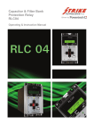
Download Catalyst Quick Start Guide
Transcript
Quick Start Guide
Introduction to the Catalyst
Quick Start Guide
1.0 Introduction to the Catalyst
1.1
What is an Autodialer/RTU?
The Catalyst RTU (Remote Telemetry Unit) functions as an auto-dialing remote alarm monitor and data
logger. Auto-dialers and RTUs are typically used at remote, unattended locations, to monitor the condition
of automatic equipment. The mission of an Autodialer/RTU is to compare inputs against alarm criteria.
Then if alarm violations occur, the RTU calls maintenance personnel (or a central station computer) to
inform them of the "out of normal" condition at the remote site. Alarm notification reports are typically
made to operators as voice reports. However, data reports to central computers can be made as well.
All user programming configurations, including recorded messages, are maintained in permanent nonvolatile flash memory within the Catalyst. This information can also be stored on a local hard disk with the
use of Alarmware™.
The Catalyst RTU incorporates extremely thorough and effective electrical surge protection, as well as
overall rugged construction, to deliver reliable operation under real-world conditions.
The RTU is factory equipped with 4 physical inputs known to the RTU as Channels. In the Catalyst RTU
channels are of two classes: Physical Input Channels and Industrial Network Channels. The RTU can
input data from channels of both classes - physical and industrial network. Furthermore, both physical and
industrial network channels can be one of two data types - Discrete or Analog.
"
"
Physical Channels are channels whose input circuitry is physically a part of the RTU hardware.
Physical Input channels are monitored and controlled directly by the RTU microprocessor hardware.
The connection between the RTU and its physical channels cannot be broken. So they will never
cause communications failure alarms, or, be unable to access channel data.
Industrial Network Channels are channels that are not physically a part of the RTU hardware. In
fact, the RTU may access Industrial Network Channels that:
(a)
(b)
(c)
(d)
physically reside in several different units simultaneously
are located in different types of equipment
may be from many different manufacturers
need not be located in close proximity to the RTU
Industrial Network Channel data is monitored and controlled over industrial networks. Industrial networks
are usually, but not always, serial data communications interfaces. Common types of industrial networks
are Modbus, Modbus Plus, and Allen-Bradley DH-485.
The most common type of device interfaced to the Catalyst RTU via an industrial network is the
Programmable Logic Controller (PLC). Data in a PLC resides in its data table. Individual locations in
the PLC data table are called data registers. Data registers can represent inputs, outputs, general-purpose
memory, and PLC status points. Almost any data register in a PLC can become a channel to the RTU.
Industrial network channel data is kept current by the RTU continually scanning (making queries to) PLC
data registers. However, unlike physical channels, industrial network interfaces may get interrupted or
Catalyst Interactive Communication System
1
Quick Start Guide
Introduction to the Catalyst
broken or may become congested by network traffic. Therefore, industrial network channel data may
become inaccessible. Industrial networks that become inaccessible can cause communications failure
alarms.
When a channel's configured alarm violation condition occurs and persists for the programmed Alarm Trip
Delay time, the channel goes into an Unacknowledged Alarm state, and the RTU begins the process of
communicating with designated destinations to deliver the specific alarm information.
The most common type of Destination is telephone numbers, to which the Catalyst places alarm
calls and delivers specific corresponding voice messages which the user has pre-recorded to identify the
exact nature of the alarm condition. However, destinations can also include other items, such as a pager, a
Fax Machine, or a remote data terminal.
The process of alarm notification continues until a proper acknowledgement has been received by the
RTU.
Certain special "global" events not associated with any particular channel can also cause alarms. Examples
are; interruption of primary power to the product, which would cause a power failure alarm (PFAIL),
or failure of industrial network interfaces to PLCs, which would cause a communications failure alarm.
Delivery of the alarm message may be in the form of a voice call directly to personnel, as described above.
Alternatively, calls may be made in data mode. With data mode calls, the product establishes modem
communication with a called device for the purpose of transmitting information in a non-voice data format.
The RTU can also be programmed to take data samples ("snapshot" readings) from its active channels on
a regular interval basis. These channel data samples can be stored in the RTU log file and/or written to the
local data logger (printer). The RTU can be called for retrieval of log file data by a remote data terminal or
Alarmware. The burden of retrieving data logs is generally on the operator. However, a configurable
parameter of the RTU allows for RTU initiated automatic transfer of logged data to the central computer,
should the log file reserve approach the overflow level before the central computer calls the RTU.
Input channels may also optionally be configured to export their contents to specific Destination
Network Addresses (DNA). This function can be used to link one point in a network to another point.
This export process refreshes at the scan rate of the industrial networks involved in the transfer process.
Note: DNA are not to be confused with destinations, to which reports are delivered only under certain conditions
such as an Unacknowledged Alarms.
1.2 Placing Phone Calls to the RTU
You may call the Catalyst RTU at any time from any telephone. The product will wait the configured
number of rings before answering and beginning a voice status report. The status report starts with the
Unit ID message, followed by a request for entry of any touch-tone digit. Entering a tone will establish that
this is to be a voice mode session, rather than a data mode (modem) session.
Exception: If PINs (Personal Identification Numbers) have been configured, the RTU will require entry of a valid
PIN before proceeding.
Next will follow any special warning messages, followed by a channel status report. The channel status
report will report only the channels whose alarm state is "other than normal". If there are no channels
Catalyst Interactive Communication System
2
Quick Start Guide
Introduction to the Catalyst
whose alarm state is "other than normal," then channel status report will simply consist of a statement that,
"All Channels Are Normal."
Note: "Other than normal" channels can include channels which were at one time unacknowledged, became
acknowledged, and are now still acknowledged but awaiting the end of the alarm reset time before becoming
rearmed.
After the channel status report (or "All Channels Are Normal" message) the user will hear a prompt
consisting of a menu of available options.
The purpose of this prompt is to invite the user do one of the following:
"
"
"
"
To acknowledge any unacknowledged alarms
To terminate the call without acknowledging any alarms
To repeat the channel status report
To enter other RTU modes such as program, search, or "read-only program"
In program mode, the user can enter keycodes to perform configuration changes. While in "read-only
program" mode the user can listen to configuration information, but cannot make any configuration
changes.
1.3 Voice and Text Messages
The RTU is capable of using both voice messages and text (data mode) messages:
Voice Messages:
" The RTU incorporates its own resident vocabulary of "canned" speech, and it also allows
users to record their own voice messages for more meaningful and descriptive reports.
" The resident speech is used to support programming operations when programming at the
Front Panel or over the phone.
" Resident speech is also used to create factory default voice messages for use in voice reports
to personnel until the user replaces them with their own recorded voice messages.
Text Messages:
" In addition to voice messages for communicating directly with personnel, the RTU provides
text messages that are included in reports to data devices such as a log file, a central station
computer, a local printer, and Fax machine.
" As with voice messages, the RTU has factory default "generic" messages, but allows users to
configure their own text messages.
Message organization (applies to both voice and text messages):
" The RTU provides for two voice messages and two corresponding text messages for use in
communicating the status of each input channel. The specific way these two messages are
used in reports depends upon whether the input channel is configured for analog (having a
continuous range of possible values) or discrete (having just two possible values, 0 or 1) data
type.
Tag Words:
" In addition to these user configurable messages, the RTU automatically appends Tag Words
to the end of each channel's status message in reports. These Tag Words provide additional
indication of the channel's state (Alarm, Normal, etc.) as distinct from its current status
reading. Factory default Tag Words are provided, but as with messages, the user may
customize them in the configuration process.
Catalyst Interactive Communication System
3
Quick Start Guide
Introduction to the Catalyst
Catalyst Interactive Communication System
4
Quick Start Guide
Introduction to the Catalyst
1.4 The RTU Front Panel
Catalyst Interactive Communication System
5
Quick Start Guide
Introduction to the Catalyst
The Front Panel keys operate as follows:
NORMAL / CHECK STATUS
DIAL OUT / PRESS TO TALK
DISARM / RE-ARM
POWER ON / POWER OFF
PROGRAM
ENTER
CANCEL
RECORD
Returns Catalyst to NORMAL mode. If already NORMAL, gives Check
Status report (a report of any channels in alarm). Also terminates calls
and reports.
Accesses phone line; prepares to dial digits as they are pressed. Press to
talk and release to listen.
Disarms unit (which prevents notification). If already disarmed, re-arms
unit and clears old alarms.
Turns unit OFF. If already OFF, turns unit ON.
Puts unit in PROGRAM mode.
Executes program code entry.
Cancels program code entry.
Records message while pressed. Requires key code in PROGRAM
mode to enable.
Note: If there are any unacknowledged alarms, pressing any of the keys listed above will acknowledge the alarms,
regardless of any PIN settings.
Front Panel LEDs operate as follows:
NORM
CHECK
LOBAT
PFAIL
TFAIL
ON when in NORMAL mode.
ON when in CHECK STATUS mode, local report being delivered.
ON when battery voltage falls below a threshold value. With fully charged battery, light
should go OFF within a few minutes of turning ON. A discharged battery may take up
to a day to fully recharge.
• If there is a BFAIL (battery below threshold value) and a PFAIL (power failure), the
LOBAT LED is ON and the battery is LOW.
• If there is a BFAIL, but no PFAIL, the LOBAT LED is ON, but the battery is
CHARGING.
ON during primary power failure and running on battery. During primary power
failure, all LEDs will blink faster than normal. Upon return of power, all LEDs will stop
blinking.
" OFF if there is no unacknowledged TFAIL
" BLINK fast during unacknowledged TFAIL
Catalyst Interactive Communication System
6
Quick Start Guide
NET
PROGRAM
RECORDING
DISARMED
PHONING
CHANNEL
LEDS
---
Introduction to the Catalyst
Net 1 PLC
" OFF if scan is OFF
" ON if scan is ON
" BLINK if scan is ON and any channels on this net are in Communication ALARM
(whether acknowledged or not)
Net 2 Printer:
" ON when enabled
" OFF when disabled
" Blink if device is flow-controlling the port
Net 3 Alarmware:
" OFF if no Alarmware™ session is active
" ON if Alarmware™ session is active
Net 4 Log File:
" ON when enabled
" OFF when disabled
" Blink when data is being lost
ON when in PROGRAM mode via Front Panel, Over the Phone, or Alarmware™.
ON when message is being recorded.
BLINK when unit is disarmed.
" ON when off-hook for any reason
" SLOW BLINK during intersession delay.
" Otherwise LED is OFF
" BLINK when channel in ALARM state
" ON when alarm acknowledged
Regardless of when a channel is alarmed, the channel alarm LED will be in sync with all
active channel alarm LEDs.
" BLINK when Log File is Full
" ON when Log File is ENABLED
" OFF when Log File is DISABLED
Note: Front panel LED representations in Alarmware™ should behave exactly as the Front Panel LEDs behave.
1.5 Manually Dialing Out and Conversing through the RTU
Occasionally it is desirable to manually place outgoing calls from the RTU in order to converse with
someone by phone line connection.
The following describes how to do this:
"
"
"
"
At the Front Panel, starting in the Normal mode, press the DIALOUT/PRESS TO TALK key, wait
until you hear a dial tone, then press the digits of the phone number you want to dial. Each digit
you press will be dialed as you press it. You will then hear the sound of the ringing at the other
end.
When you hear the phone answered, press and hold the same DIALOUT/PRESS TO TALK key as
you speak to the person on the line. Release the key to listen. Continue the conversation in this
manner. The microphone at the top of the front panel will capture your voice for this purpose.
To end the call, press NORMAL.
If you are at the Front Panel when a phone call is in progress, you may suspend the message
report and converse with the person on the other end by pressing the DIALOUT/PRESS TO
Catalyst Interactive Communication System
7
Quick Start Guide
Introduction to the Catalyst
TALK key as described above. There will be no additional dialing, since connection has already
been established. To end the call, press NORMAL.
NOTE: Pressing these keys on the front panel will automatically acknowledge any unacknowledged alarms,
regardless of any PIN configurations.
1.6 Programming/Configuring the RTU
There are three different methods to configure the Catalyst RTU:
1.
2.
3.
Using the keypad at the Front Panel
Using the touch-tone keys of a voice telephone
Using the Alarmware™ configuration software
One Important Exception: User Recorded Voice Messages
The initial recording of user recorded voice messages must be done either at the RTU front panel or via a voice
phone call to the RTU, rather than from Alarmware™. However once the messages are recorded, the
recorded message data can be transferred back to the computer running Alarmware™ just as with other
configuration data, to be saved for later use. This transfer process does take substantial time, since
recorded messages require a lot of data in comparison with other configuration settings.
1.6.1 Programming with Alarmware™ Configuration Software
Alarmware™ is an application program used primarily to configure the Catalyst. The application runs on
personal computers running the Microsoft Windows 95 or 98 and Windows NT operating systems.
In addition to configuring the Catalyst, Alarmware™ can be used to:
"
"
"
"
Monitor alarms
Observe channel values and statuses
Transfer and manipulate RTU log files
Perform various diagnostic procedures relevant to the Catalyst
Using Alarmware™, configuration files can be created, retrieved from storage, and retrieved from, or sent
to the Catalyst. Configuration files can also be edited off line, with any changes exported to the RTU a
later time. This transfer of configuration files between the RTU and a PC computer running Alarmware™
can be accomplished locally via a serial port connection to the RTU, or remotely via a telephone/modem
connection.
1.6.2 Programming from the Front Panel or Over the Phone
In addition to programming via Alarmware™, many configurable settings may also be programmed from
either the Catalyst Front Panel, or by using touch-tone entries from a voice phone.
Catalyst Interactive Communication System
8
Quick Start Guide
The Alarmware™ Program: Brief Overview
2.0 The Alarmware™ Program: Brief Overview
2.1 What is Alarmware™?
Please Note: This set of topics is meant to provide a basic overview of the Alarmware™ software program. The
Operator's Manual section covers terminology, concepts, and the use of Alarmware™ in more detail.
Alarmware™ is a software application designed for use in combination with personal computers running
Microsoft Windows™ and RACO's Catalyst. Alarmware™ allows an operator to configure an RTU, to
monitor alarms, and to perform various diagnostic routines relevant to the RTU.
Caution: Configurations changed by means other than Alarmware™, including speech data, should still be
subsequently imported into Alarmware™ so that they will be available should there ever be need to restore
configurations for the RTU.
When opened, Alarmware™ presents three top menu choices in addition to Help and Exit:
SELECT RTU
OPTIONS
LOG FILE
Used to select which RTU to manage. This is the most commonly selected top
menu item.
Includes settings for:
" The com port and modem on the computer running Alarmware™
" An optional Alarmware™ retained PIN (Personal Identification Number)
" Session timeout limit for Alarmware™ (not the Catalyst)
" AutoSave interval for automatic saving of configuration files to disk when
working offline.
Allows opening a currently saved log file for a specific RTU.
2.2 Selecting an RTU and Using Alarmware™ to Configure It
Alarmware™ can be used to configure the Catalyst RTU online or offline. First, a database configuration file
must been created within Alarmware™. To create a Catalyst database, use the ADD or EDIT buttons on
the initial Select RTU dialog box. You now have three choices:
1) By connecting with the RTU to be configured, via Phone or via Serial port, and working online. When
you make configuration changes as required from the Configuration Settings menu, both the
connected RTU and the corresponding Alarmware™ configuration file for that RTU will be updated
immediately as each change is made.
2) By delaying connection and working offline. Selecting the RTU and making configuration settings or
changes within Alarmware™ as required. After ending the offline session you would again select the
same RTU to be configured or updated, and then make online connection as described above. In this
case, a Database Mismatch dialog will appear (because the two databases no longer match). Choose
Export to RTU. Alarmware™ will write (export) the data back to the RTU. When the process is
completed, your RTU will now be configured as its corresponding file within Alarmware™ was
configured.
Catalyst Interactive Communication System
9
Quick Start Guide
The Alarmware™ Program: Brief Overview
3) By using one RTU configuration file as the starting point for the configuration of another RTU. Using
the Copy feature, available from the top menu after a configuration session is underway. This can save
substantial time in systems with multiple RTUs requiring similar configurations.
Note: When an RTU is added, the model number must be correctly selected from the list presented before
proceeding.
When working with an RTU configuration offline, an Offline Status Window shows a representation of the
front panel LEDs. When offline, clicking on channel LEDs, or on Net LEDs, brings up a corresponding
configuration dialog box for the item selected.
When working with an RTU configuration online, an Online Status Window shows a similar representation
of the front panel LEDs, but in this case the window provides a "live" display of how they actually appear
currently on the RTU Front Panel.
From this Online Status window, you can click on the PLC LED, to view the status and error history for
the PLC Net. Click on the Printer, Aware, or LogFile LED to view or change the device settings.
Also from this Online Status window, you can click on a channel LED to view the current Direct Channel
Reading for that channel, along with its Raw Value reading and "Alarm/Normal" state.
The Online window also contains 4 button controls, to Arm/Disarm, Acknowledge Alarms, Disconnect
RTU and check an External Net Address.
In either case, clicking Configuration on the menu allows you to proceed with RTU configuration.
Note: At the end of any Alarmware™ online session, if there are any unacknowledged alarms, they will be
cleared out (corresponding to what otherwise happens when the respective Alarm Reset Timers time out). Then,
if there are any alarm criteria violations existing, after the respective Alarm Trip Delays elapse, new
unacknowledged alarms will be created.
2.3 Configuration Items within Alarmware™
With a Catalyst selected, and working online or offline, the following configuration items will be available
from the Alarmware™ Configuration menu:
"
"
"
"
"
"
"
"
Channel Settings – Alarm violation criteria, reporting formats, etc.
Device Settings – Phone, Printer, Log File, and various port settings
Destination Settings – Phone numbers, destination types, etc.
Message Settings – Text messages of all types
Session Parameter Settings – Timeouts, Delays, Redial Attempts, etc.
Annunciation Settings – Common trip delay, phone fault test, etc.
PIN Settings – Personal Identification Numbers
Cleardown -- Features
Catalyst Interactive Communication System
10
Quick Start Guide
The Alarmware™ Program: Brief Overview
2.4 Channel Settings
The Channel Settings dialog box allows you to select any particular channel you need to configure. Each
channel to be used must be given a Source Network Address (SNA). The SNA identifies the specific address
location on the RTU or industrial network that this channel will continually scan. The physical channel data
types (discreet or analog) should be correctly set before entering other channel settings. See 2.10.2 Device
Settings, Physical IO tab in Operator's Manual to set the physical channel data types.
You may also optionally enter a Destination Network Address (DNA). The DNA (not to be confused with
destinations), identifies an address location to which the channel would continually write its value at the
RTU scan rate.
Other items to enter from this dialog box include:
"
"
"
"
"
The Reporting Format and Value Scaling that specify how raw values scanned are translated into
readings and reports.
The Alarm Violation Criteria, which specifies what (if anything) constitutes an alarm violation.
The Alarm Trip Delay (if different from the factory default or from your own established
Common Alarm Trip Delay).
This dialog box also includes a Messages button that provides a shortcut to the corresponding
Messages dialog box for this particular channel.
Copy From and Copy To buttons facilitates setting up similar channels within a given RTU
configuration. Messages (voice and text) are not included in this copying process.
2.5 Device Settings
The Device Settings dialog box includes tabs for the following device settings:
"
"
"
"
"
"
"
"
Phone Configuration: Contains parameters for phone configuration
Physical Inputs: Allows you to select the physical channel type (analog or discrete)
Modbus Port: Ability to modify Modbus parameters and timers
Alarmware Port: The only parameter that can be changed is the baud rate connecting the
Catalyst and Alarmware.
Time & Date: Set the clock and associated parameters
Log File: When enabled, allows you to save Catalyst data, filtered by selection.
Printer: When enabled, text messages are sent to the local data logger, filtered by selection.
Modem settings: (not normally a user configured item)
2.6 Destination Settings
The Destination Settings dialog box is used to establish the Destination number and Destination type, as
well as a name that will be assigned to this Destination in text reports. The text ID name entry is
important in order for the text reports to be fully descriptive.
In general, a Destination is considered a "receiver" of reports that are sent by the Catalyst when certain
conditions (such as an Unacknowledged Alarm) exists.
Available Destination types are:
Catalyst Interactive Communication System
11
Quick Start Guide
"
"
"
"
"
"
"
The Alarmware™ Program: Brief Overview
Telephone (for personnel to receive alarm calls)
Numeric/Beeping Pager
Alphanumeric Pager
Fax Machine
Remote Data Terminal (a central computer running a terminal program such as HyperTerm or
Procomm)
PBX/Local Paging System
Central Station to be used in conjunction with RACO SCADA application.
The selection of Destination type in turn determines the other relevant configuration items for this
Destination, which are displayed under various tabs in the Destination Settings dialog box. For example,
the most common Destination type is Telephone, for which a telephone number is an important
parameter to set.
The Destination Settings dialog box also has a Groups button, which takes the user to the Destination /
Channel Groups dialog box. This provides a convenient means to link selected destinations to selected
channels (or alternatively, channels to destinations). For example, grouping might be used to cause
channels dealing with electrical problems to report to the electrical crew, plumbing problems to report to
the plumbing crew, etc.
The factory default is for all channels to be linked to all destinations.
The Copy From and Copy To buttons facilitate the easy configuring of multiple destinations with similar
settings.
2.7 Message Settings
First select a Message "type". The choices are:
"
"
"
"
"
RTU Name
Net Name
Destination Name
PIN Name
Channel Status
For each type selection, a specific corresponding format is presented for entry of the corresponding
name(s) or message(s) to be used in text reports. In the case of channel status messages, there are two text
messages for each channel. The specific way in which the two messages are used to report the status of the
channel depends upon whether the channel is analog type (having a continuous range of possible values) or
discrete type (having only two possible values, 0 or 1). In either case, the dialog box provides guidance as
to how to enter the desired text messages.
There is also a Tag Words button that presents a dialog box for entry of user-defined Tag Words, which
are automatically included in channel status text reports to indicate the state of a channel, as distinct from
its current reading.
Provision is also included for limited management of user recorded speech messages corresponding to the
selected message item.
2.8 Session Parameters
Catalyst Interactive Communication System
12
Quick Start Guide
The Alarmware™ Program: Brief Overview
The Session Parameters dialog box includes settings for:
"
"
"
"
"
"
"
The number of redial attempts to reach a given Destination (if a busy signal is detected on the
first try)
The Session Inactivity timeout period after which the RTU will terminate a Front Panel, Over
the Phone or Alarmware™ session if user interaction ceases
The basis for reporting priority (lowest channel number versus lowest Destination number)
The Intersession Delay between alarm call reports
Microphone listening on/off (provides for a listening period via the RTU built-in microphone)
During voice sessions, give the Menu Prompt the number of times configured here.
When starting a data session , wait no more than this number of seconds to determine the
protocol
2.9 Annunciation Settings
The Annunciation Settings dialog box allows the user to set:
"
"
"
"
"
"
Common Alarm Trip Delay -- which is used by default for all active channels. This value may be
customized for each channel.
Power Failure Alarm Trip Delay – separate from Channel trip delays.
Alarm Reset Time -- Controls how long, after acknowledgement, a channel will have its
Acknowledged Alarm state cleared to NORMAL. The channel is reset so that it will be capable of
tripping into alarm when the next violation occurs.
Interval for checking phone line – Phone line connection test schedule.
Test Callback Schedule – set base time and frequency of Autocalls.
Calls to RTU Acknowledge Alarms? -- Whether or not an incoming call automatically
acknowledge alarms.
2.10 PIN Settings
The PINs dialog box allows you to add and edit PINs (Personal Identification Numbers). When PINs are
configured, the RTU will require entry of a valid PIN number before allowing various levels of operations.
Each PIN configuration requires:
"
"
"
"
an ordinal PIN number
the PIN code
a PIN Name which will be included in text reports to provide an audit trail for various operations
a Privilege level which determines the individual's ability to listen to reports, acknowledge alarms,
change RTU configurations (excluding PIN settings), and perform administrative level operations
(including PIN settings).
A Separate provision is made for an optional retaining of one of these configured PINs. This feature enables
the PIN to be entered automatically upon connecting with an RTU. This will save the Alarmware™
operator from having to manually enter the PIN.
Note: Even if PINs are programmed, access to front panel operations on the RTU does not require PIN entry.
Catalyst Interactive Communication System
13
Quick Start Guide
The Alarmware™ Program: Brief Overview
2.11 Cleardowns
The Cleardowns dialog box is used to clear down RTU settings and messages to factory default values.
Cleardown should be used with caution. It takes considerable time to record a large set of voice messages,
and the voice messages will be deleted as part of the cleardown process.
Catalyst Interactive Communication System
14
Quick Start Guide
Using this Documentation
3.0 Using this Documentation
3.1 Typographic Conventions
Throughout this documentation, both in the Online Help System and in this User's Manual, various
conventions are used to identify pertinent information.
"
"
"
All Notes and Exceptions are placed in Italics. Notes and Exceptions represent important additional
information. Also, some Help topics which are associated with the Help button within certain
dialog boxes, have an italicized description of how to access the dialog box, appearing at the
beginning of the topic, for the benefit of users who are referring to the printed manual version of
the Help System.
In the Online Help System, Links to other Help pages are underlined and green in color.
Items that are ALL CAPITALS reference the names of keys, lights, LEDs, or when referring to a
mode to which the RTU is placed (for example, PROGRAM mode).
3.2 Helpful References
While using this documentation, there are several sections that you may find quite helpful as references.
This is true for both the User's Manual, and the Online Help System. For Online Help you may wish to
utilize the Bookmark feature within Windows Help to mark these sections for easy reference.
Catalyst Interactive Communication System
15
Quick Start Guide
Using this Documentation
3.3 How To Print Documentation
"
"
"
"
"
Help Topics — To print a Help Topic, click on the Print button at the top of the topic window.
Tables — To print a table, select desired table and click on the Print Topic button at the top of
the topic window.
Worksheets — When Worksheets are selected, the file will be launched in the appropriate
application. To print the worksheet, select “Print” from the application's File menu.
Code Table — To print the Code Table that contains the Keycodes for use in Front Panel or
Over the Phone programming of the RTU, click on the Keycodes button on the Help toolbar of
any help topic. Next, click on the Print Keycode Table link.
Entire Help Manual or Large Numbers of Help Topics — To print large numbers of help
topics start from the Help Contents dialog box. This is the dialog box you first see when selecting
Help from the Alarmware™ main menu. Alternatively, in any help topic click on the Contents
button. Select the Contents tab in the dialog box. Any selected book or page (topic) will be
printed when the Print button (at the bottom of the dialog box) is clicked. When a book is
selected for printing everything within that book will be printed including all topic pages plus other
books and pages within the selected book. By selecting in turn, each of the outermost books in
the table of contents, the entire Help System could be printed.
Catalyst Interactive Communication System
16


