1
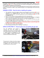
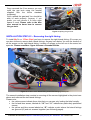
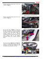
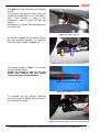
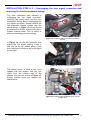
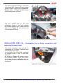
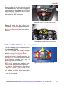
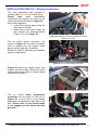
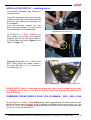
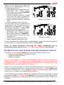
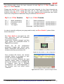
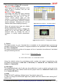
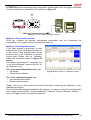
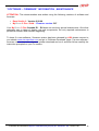
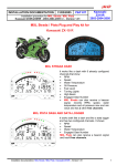
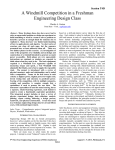
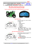
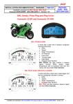
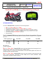
INSTALLATION
DOCUMENTATION
5/04/2005
KIT MOTO
Installation procedure for MyChron 3 Plus / Gold
Yamaha R1-R6 2002-2003-2004 kit – Version 1.00
Yamaha R1-R6
2002-2003-2004
Yamaha R1 and R6 MyChron 3 Plus Gold Plug and Play kit
KIT DESCRIPTION
The kit for Yamaha R1-R6 is composed of the following objects:
•
•
•
•
•
•
MyChron 3 Plus or MyChron 3 Gold.
Plug and play wiring for MyChron 3 Plus or MyChron 3 Gold.
Installation kit including: 1 bracket, screws, anti-vibration mountings, washers.
Gyroscope (optional – available for GOLD version only) needed to track maps.
CD-ROM including Race Studio 2 software.
Documentation.
The kit for Yamaha R1-R6 has been developed for the following cubic capacities: 600 cc and
1000 cc. Please refer to the following table to understand which Yamaha R1-R6 is supported
by our kit.
Cubic capacity (cc)
Year 2002
Year 2003
Year 2004
R6 - 600
√
√
√
R1 - 1000
√
√
•
√ = supported
• = NOT supported
MyChron 3 Plus / Gold - Yamaha R1-R6 version has been designed and developed to be a
“plug and play” system you can connect to the “on-board” wiring.
The aim of this kit is to merge the functionalities of the stock dash together with these of a
professional data acquisition system.
MyChron 3 Plus / Gold - Yamaha R1-R6 version may be used both on track (lap times, split
times, engine parameters, gyroscope to track maps) and on street (odometer, water
temperature, oil pressure alarm, fuel level).
Installation documentation: MyChron 3 Plus/Gold plug and play kit - Yamaha R1 - R6 – Version 1.00
1
The gauge, as the stock dash, is powered by the bike’s master switch. Moreover, when
installing your MyChron 3, you do not have to cut, bend or drill anything: each component of
the kit has been designed to be plug and play.
The gauge has to be connected to the standard head light using the bracket supplied with the
system. The bracket is made in grey anodized Ergal, so to be lightweight and mechanically
resistant.
GENERAL NOTES – Read this before installing the system
•
•
•
•
•
•
•
This installation manual has been written using photographs made during MyChron 3
installation on a Yamaha R6 bike. This is the reason why you can find slight
differences in the screws, connectors positions if you are installing your MyChron 3 on
a Yamaha R1 bike.
Do not cut any wiring: the wiring supplied with the kit is plug and play.
Please, be careful not to damage the on-board connectors when plugging / unplugging
them. In the following pages is described how to correctly manage them.
Do not install the system when the engine is hot. The on-board connectors are quite
near to the engine and you can burn yourself.
The space under the gas tank is quite confined: be careful not to hurt yourself when
plugging and unplugging the connectors. If necessary, please remove the gas tank
in order to have a wider available space.
Be careful not to loose screws and washers.
Do not damage the fairing when installing / uninstalling it.
INSTALLATION STEP # 1 –Removing the seat and uplifting the gas tank.
The first installation step consists in
removing the seat and uplifting (or
removing) the gas tank. The seat is fixed
to the bike with two screws located under
it, whose location is highlighted by two
arrows in Figure 1. Please unscrew the 2
screws and remove the bike seat.
Figure 1: location of the seat screws.
The gas tank is fixed to the bike chassis
with two Hex screws; please remove them.
In Figure 2 you see the location of the
screws and how to remove them.
Figure 2: unscrewing the gas tank screws.
Installation documentation: MyChron 3 Plus/Gold plug and play kit - Yamaha R1 - R6 – Version 1.00
2
Once removed the 2 hex screws, you may
uplift the gas tank using the bracket
supplied with the bike’s standard
equipment.
Once uplifted the gas tank You should be
able to work properly. Anyway, if you
prefer, you can remove it to have more
space to work. Please refer to the bike
user manual to know how to remove
the gas tank.
Figure 3:Uplifting the gas tank.
INSTALLATION STEP # 2 – Removing the right fairing.
To install MyChron 3 Plus /Gold you have to remove the right lateral fairing. Of course you
can also choose to remove both lateral fairings. Anyway here below You see the location of
all the screws on the right lateral fairing. Location of screws on the left one is the same, but
specular. Please remember: figure 4 shows a Yamaha R6 bike.
9
6
7
5
8
9
12
13
14
4
3
G
2
1
11
10
Figure 4: Location of the lateral fairing screws and fairings groove point.
The second installation step consists in removing all the screws highlighted in the photo here
above and unthread the two lateral fairings.
Please note:
• the yellow arrows indicate three clips that you can see only looking the bike frontally.
• the red and blue arrows, labeled as “10” and “11” indicate two particularly positioned
screws
• the yellow and blue arrows labeled as “G” indicate a point where the lateral fairings
are grooved (G) and not screwed together (see following pages).
Installation documentation: MyChron 3 Plus/Gold plug and play kit - Yamaha R1 - R6 – Version 1.00
3
Please unscrews screws from 1 to 5, red
circled in Figure 5.
5
4
3
1
2
Figure 5: location of screws from 1 to 5
Please unscrews screws from 6 to 9, red
circled in Figure 6
6
7
8
9
Figure 6: location of screws from 6 to 9
As you can see in Figure 7, under the
bike are two screws. The first one, labelled
as 10, is screwed into a metal cut threads
clip fixed to the right fairing, while the
second, labelled as 11, is screwed
horizontally into the lateral fairings so to fix
them together and to the radiator
protective fairing too. Please unscrew
them.
11
10
Figure 7: location of screws 10 and 11 (internal view).
As you can see in Figure 8 and Figure 9,
under the head-lights (looking the bike
frontally), are three clips, labelled as 12,
13 and 14, that should be removed.
12
13
Figure 8: location of clips 12 and 13
Installation documentation: MyChron 3 Plus/Gold plug and play kit - Yamaha R1 - R6 – Version 1.00
4
In Figure 9 is red circled the clip labelled
as 14.
To remove a clip, please, insert a tip in its
central hole and press until You hear a
click. Then remove it using a flat
screwdriver: insert it under the clip and
rotate it.
Remember to repeat this proceeding for
the three clips.
14
Figure 9: location of clip 15
As shown in Figure 10, the lateral fairings
are not screwed together, but grooved
with two hooks, shown in Figure 11.
G
G
Figure 10: fairings grooving point (internal view)
The hooks shown in Figure 11 connects
the two lateral fairings.
Please be careful to well fix the two
hooks that connect the two lateral
fairings when re-mounting them.
Lateral fairings grooving hooks
Figure 11: Lateral fairings hooks
To separate the two fairings, unthread
them as shown in Figure 12 and remove
the right lateral fairing.
Figure 12: Slackening the groove of the lateral fairings
Installation documentation: MyChron 3 Plus/Gold plug and play kit - Yamaha R1 - R6 – Version 1.00
5
INSTALLATION STEP # 3 – Unplugging the turn signal connector and
removing the front transparent fairing.
The third installation step consists in
unplugging the turn signal connector,
removing the lateral mirror and the front
transparent fairing. Before unplugging the
turn signal connector, please remove the
little protective chassis located over the
lateral fairing. In Figure 13 are red circled
the screws that fix this chassis to the bike.
Please unscrew them. This is useful to
allow you inserting your new wirings.
Figure 13: location of the screws of the protective
chassis.
In Figure 14 you see the connector that
makes the turn signal working. It has a
little clip on its top, please press it and
then unplug the connector as in the figure
on the right.
Figure 14: the turn signal connector.
The lateral mirror is fixed to the front
chassis with two screws, that you can
reach from the internal side of the
chassis; they are red circled in Figure 15.
Please unscrew them and remove the
lateral mirror.
Figure 15: location of the left lateral mirror screws
(inside view).
Installation documentation: MyChron 3 Plus/Gold plug and play kit - Yamaha R1 - R6 – Version 1.00
6
The front transparent fairing is connected
to the head-light chassis with four screws
whose location is red circled in Figure 16.
Please note: in Figure 16 the screws
have already been removed.
Figure 16: the front transparent fairing screws.
The four screws that fix the front
transparent fairing to the bikes chassis
are Phillips Recess ones. Please unscrew
them, as in Figure 17, and remove the
front transparent fairing.
Figure 17: unscrewing the transparent fairing screws
INSTALLATION STEP # 4 – Unplugging the on board connectors and
removing the stock dash
The fourth installation step consists in
unplugging the “on-board” connector and
removing the stock dash.
On the back of the stock dash, protected
by a plastic cover, is the 16 pins AMP
connector.
As shown in Figure 18, please remove
the protective plastic cover, push down
the locking tongue (highlighted with an
arrow) and pull out the connector from the
dashboard.
Figure 18: unplugging the on board dash connector
Installation documentation: MyChron 3 Plus/Gold plug and play kit - Yamaha R1 - R6 – Version 1.00
7
The stock dash is fixed to the bike with 3
screws located on its back and red circled
in Figure 19, while the stock wirings are
connected to the stock dash with a 16 pins
AMP connector, highlighted with an arrow
in Figure 19. Please unscrew the screws
and unplug the AMP connector.
Figure 19: Location of the stock dash screws.
Figure 20 shows the bike without the
stock dash. In the photograph are yellow
circled the three holes where your
MyChron 3 Plus / Gold has to be fixed to
the bike.
Figure 20: the stock dash has been removed
INSTALLATION STEP # 5 – Assembling the kit.
The fifth installation step is assembling the
kit for Yamaha R1-R6.
The kit You receive, has already mounted
the four anti-vibration mountings on the
back of your MyChron 3 Plus / Gold;
Install your MyChron 3 Plus / Gold on the
aluminium bracket fixing the bracket to
your MyChron 3 in correspondence of the
4 anti-vibration mounting and using 4
screws and 4 Grover washers.
Figure 22 shows the correct assembly of
MyChron 3, bracket and washers (rear
view). Points highlighted in the figure are:
• in red the four connection point where
MyChron 3 Plus / Gold is fixed to its
bracket (supplied with the kit)
• in yellow the three holes where the
screws used to fix the system to the bike
have to be inserted.
Figure 21: MyChron 3, bracket – rear view
Installation documentation: MyChron 3 Plus/Gold plug and play kit - Yamaha R1 - R6 – Version 1.00
8
INSTALLATION STEP # 6 – Wirings connection.
The sixth installation step consists in
installing MyChron 3 Plus / Gold wiring.
Please
note:
water
temperature
connectors and speed one have to be
connected a part as shown in Figure 22.
We would suggest to:
• let the new wirings pass along the
right side of the bike
• insert them in the space under the
little chassis you removed before
(Figure 13), as in Figure 22.
Figure 22: installing the water temperature and the
speed connectors.
The on board speed connector, red
circled in Figure 23, is a white connector
and is located over the engine carter
placed on the right side of the bike.
Please be careful, because the available
space is really small.
Figure 23: the on board speed connector.
Figure 24 shows the engine carter (red
circled) and the arrows indicate the point
behind where the white on board speed
connector is located.
Figure 24: location of the on board speed connector
The on board water temperature
connector can be green, as the one in
Figure 25 or grey and is very deeply
hided down on the bottom right side of the
bike. Please note: if you cannot reach
it, we suggest you to remove the bike
gas tank.
Figure 25: the on board water temperature connector
Installation documentation: MyChron 3 Plus/Gold plug and play kit - Yamaha R1 - R6 – Version 1.00
9
INSTALLATION STEP # 7 – Installing the kit.
The seventh installation step consists in
installing the kit.
Once the connector has been correctly
installed, please place the black anodized
aluminium box between the bracket and
the headlight.
Once the channels interface box has
been correctly installed, you may mount
the assembled kit on the head light.
Figure 26: the aluminum box.
To fix MyChron 3 Plus / Gold to the
bike, please use screws and washers
supplied with the kit and screw them in
the holes yellow circled in Figure 21, as
shown in Figure 27.
Figure 27: fixing MyChron 3 Plus / Gold to the bike.
Figure 28 shows MyChron 3 fixed to the
bike. Fixing points are yellow circled in
the figure and MyChron 3 connector is
not connected yet.
Figure 28: MyChron 3 correctly installed (rear view)
PLEASE NOTE: before re-mounting the fairing, the mirror, the seat and the gas tank,
we suggest You to turn on the bike in order to check the system’s integrity and its
correct working.
FIRMWARE FOR MYCHRON 3 PLUS / GOLD YAMAHA – 2002 – 2003 - 2004
As your MyChron 3 Plus / Gold Yamaha has been designed both for street and track use,
and as the information the driver wants to display are different for street and track use, your
MyChron 3 Plus / Gold Yamaha is equipped with a special firmware version which provides
you a second virtual dashboard.
Installation documentation: MyChron 3 Plus/Gold plug and play kit - Yamaha R1 - R6 – Version 1.00
10
When you are driving on a street, the
display is set to “street mode” and shows
the following parameters:
● RPM graphical bar: settable upper limit;
● RPM digital value / Battery voltage:
upper right corner (button VIEW/QUIT
to switch between the two);
● Total non-resettable odometer / Speed
in the lower right corner (use button >>
to switch among odometer and speed);
● Partial resettable odometer: upper left
corner;
● Water temperature: lower left corner.
Once you start running on a track and your
gauge triggers a lap (you pass in front of a
switched-on lap transmitter), the display
automatically switches to “track mode”
and shows the following parameters:
● RPM graphical bar: settable upper limit;
● RPM digital value / Battery voltage /
Speed: upper right corner (VIEW/QUIT);
● Lap / split times in the lower right corner
(use button >>);
● Oil pressure in the upper left corner;
● Water temperature: lower left corner.
Figure 31: Street display
Figure 32: Track display
In order to step back from “track mode” to “street mode”, please switch off the gauge and
then re-switch it on. The gauge sets automatically to “street mode”.
NOTE: for further information concerning the display management and its
configuration, please refer to the MyChron 3 Plus / Gold / Gold XG user’s manual.
MYCHRON 3 PLUS / GOLD YAMAHA CONFIGURATION [RACE STUDIO 2]
Your MyChron 3 Plus / Gold Yamaha may be interfaced with the PC in order to:
●
download the data stored in the internal memory;
●
upgrade the gauge’s firmware;
●
configure the gauge.
Once you buy a MyChron 3 Plus / Gold Yamaha, it already includes a configuration
properly developed for your Yamaha bike: all sensors, calibration curves, engine parameters,
speed parameters, etc… have already been set to a default value which guarantees you the
possibility to plug in the input cable and start running.
Anyway, if you wish to change, for instance, the RPM upper value or the shift lights, if you
wish to add a potentiometer sensor or a gyroscope on your MyChron 3 Gold Yamaha and
you need to calibrate them, if you change the crown or the pinion with a “different teeth
number” one, you need to use our software Race Studio 2.
The CD-ROM including software, USB drivers, installation documentation and user’s manual
is included in the MyChron 3 Plus / Gold Yamaha kit. If you have any doubt concerning the
software or the USB drivers installation, please refer to the installation manual included in the
CD-ROM.
Installation documentation: MyChron 3 Plus/Gold plug and play kit - Yamaha R1 - R6 – Version 1.00
11
The following table shows the input channels for both MyChron 3 Plus Yamaha and
MyChron 3 Gold Yamaha.
Please note that MyChron 3 Plus has no free input channels (i.e. the 4 input channels are
sampled from the “stock” wiring and there are no “free cable-connectors” for external
sensors), while MyChron 3 Gold has 3 free input channels and a gyroscope input which
need to be configured and calibrated using the software Race Studio 2.
MyChron 3 Plus Yamaha
Ch. 1
Ch. 2
Ch. 3
Ch. 4
Water temperature
Oil pressure switch
Fuel level
Turn signal
MyChron 3 Gold Yamaha
Ch. 1
Ch. 2
Ch. 3
Ch. 4
Gyroscope
Water temperature
Free input channel – use Race Studio 2
Free input channel – use Race Studio 2
Free input channel – use Race Studio 2
Use Race Studio 2
In order to correctly configure your gauge and to easily use Race Studio 2, please follow
these instructions.
Run Race Studio 2 and select the “M3
Auto - Moto Plus / Gold / XG” pushbutton
in the buttons toolbar.
Press button “System manager” and then
“New” button: the screenshot shown in
Figure 33 is prompted.
Please,
set
all
the
configuration
parameters (Logger type, vehicle name,
speed, temperature and pressure unit of
measure) and then press button OK.
Figure 33: Race Studio 2 – New configuration
Once pressed OK button, the System
manager window is prompted on your
monitor, as shown in Figure 34.
In order to correctly configure the input
channels, please select a configuration
among the available ones (in Figure 34,
for instance, there are 4 available
configurations: the yellow-highlighted is
the selected one) and press button
“Channels”.
Figure 34: Race Studio 2 – System manager window
Installation documentation: MyChron 3 Plus/Gold plug and play kit - Yamaha R1 - R6 – Version 1.00
12
The screenshot in Figure 35 is prompted.
MyChron 3 Plus Yamaha.
This Logger has no input channels, so this
page is just a summary and you can
change nothing.
MyChron 3 Gold Yamaha.
This logger has three free input channels
(CH. 2, CH. 3 and CH. 4). Clicking in the
correspondent cell (row “CH_2”, “CH_3”,
“CH_4” column sensor type) you can
choose in a long list of predefined sensors
or set a custom sensor, selecting “Custom
sensor manager”. Moreover you can set
channel name and sampling frequency.
Figure 35: Race Studio 2 – Channels window
When all sensors have been set, please
press “Configuration button”.
Configuration window, shown in Figure 36,
allows you to set shift lights and alarm
treasure value, to change the unit of
measure, to modify speed parameters,
etc…
Figure 36: Race Studio 2 – Configuration window
1) Speed:
The speed sensor on your Yamaha bike is installed on the jackshaft that connects the
gearbox to the pinion. The number of magnets installed on the jackshaft is 78 for Yamaha R1
and 75 for Yamaha R6.
The wheel circumference written in the proper cell is an “equivalent circumference” calculated
using the following formula:
Equiv Circumf =
Wheel Circumf * N p
Nc
Np = Pinion teeth number - Nc = Crown teeth number
Using the default values for crown/pinion teeth number and wheel circumference, the
equivalent circumference is 1980 mm (77.95 inches) for Yamaha R1 and 1960 mm (77.16
inches) for Yamaha R6.
2) Shift lights:
The values described in the 5 cells may be modified by in order to switch on the led at the
desired RPM value. The 5 default values are the proper ones for a Yamaha R1 1000 cc and
for a Yamaha R6 600 cc.
3) RPM:
Please, DO NOT modify the “Multiply factor” (the default value is /1).
In order to change the RPM scale upper limit, please select the desired value among the 7
default ones.
Installation documentation: MyChron 3 Plus/Gold plug and play kit - Yamaha R1 - R6 – Version 1.00
13
4) Channel 1 Alarm:
As previously described, channel 1 is used to sample water temperature.
The alarm for channel 1 is defined as a “Maximum alarm”, i.e. the led is switched on when
water temperature is higher than the threshold value.
The default value is 90 °C that corresponds to 194 °F. Please note: if you are using °F unit of
measure you have to manually insert the °F value corresponding to °C value.
5) Channel 2 Alarm:
If you have a MyChron 3 Gold Yamaha, you may set the proper threshold values
corresponding to the sensor you have installed on channel 2.
If you have a MyChron 3 Plus Yamaha, the 2nd channel is used for oil pressure switch.
Please, do NOT modify the threshold values. The default values for this alarm are:
●
HIGH → LED: none → Value: 0
●
LOW → LED: 2 → Value: 2
6) Channel 3 Alarm:
If you have a MyChron 3 Gold Yamaha, you may set the proper threshold values
corresponding to the sensor you have installed on channel 3.
If you have a MyChron 3 Plus Yamaha, the 3rd channel is used for fuel level. Please, do
NOT modify the threshold values, otherwise you might run out of petrol. The default values
for this alarm are:
●
HIGH → LED: none → Value: 200
●
LOW → LED: 3 → Value: 100 (corresponding to 4 litre – 1 gallon)
7) Channel 4 Alarm:
If you have a MyChron 3 Gold Yamaha, you may set the proper threshold values
corresponding to the sensor you have installed on channel 4.
If you have a MyChron 3 Plus Yamaha, the 4th channel is used to turn signal. Please, do
NOT modify the threshold values, otherwise you might not see the turn signal on the display.
The default values for this alarm are:
●
HIGH → LED: 4 → Value: 400
●
LOW → LED: none → Value: 0
8) Gear sensor:
Yamaha plug & play kit allows you to sample the gear directly from an “on-board” neutral
sensor installed inside the gearbox. To allow your MyChron 3 sampling the gear, please do
NOT modify the gear sensor default configuration, that is set to calculated with neutral
signal.
Please note: if you notice that engaged gear number shown on your MyChron 3 Plus / Gold
gear display does not correspond to the really engaged gear, you need to re-start gear
calculation procedure. Please refer to you MyChron 3 Plus /Gold user manual to get further
information concerning the gear calculation procedure.
Once you set the desired input channels on your MyChron 3 Gold Yamaha and/or you
set the desired threshold values for the alarm led of the shift lights, you have to
transmit the configuration to the logger: to do so, please press OK button and then
“Transmit” button on the next screenshot.
Installation documentation: MyChron 3 Plus/Gold plug and play kit - Yamaha R1 - R6 – Version 1.00
14
ATTENTION: before transmitting the configuration, please ensure that the logger is switched
on and connected to a switched on PC as shown in Figure 37.
Figure 37: How to connect the logger to the PC
MyChron 3 Plus Yamaha owners:
Once you modified the desired configuration parameters and you transmitted the
configuration, your logger is ready for street and track use.
MyChron 3 Gold Yamaha owners:
If you have installed a gyroscope (to map
tracks) and/or a fork travel potentiometer (or
a rear shock travel potentiometer), these
sensors have to be calibrated to sample
correct data. Please click on “Calibrate”
button: the screenshot shown in Figure 38
appears.
The sensors are divided in 2 categories: the
“to be auto-calibrated” sensors and the “to
be calibrated” ones.
The “to be auto-calibrated sensors” are:
● Gyroscope
● Potentiometer distance
Figure 38: Race Studio 2 – Calibration window
The “to be calibrated sensors” are:
● Zero based potentiometer
● Mid zero potentiometer
Please, refer to the user’s manual for further information concerning the calibration / autocalibration procedure.
Once finished calibrating/auto-calibrating the sensors, you have to transmit the configuration
to the logger pressing button “Transmit calibration” inside the “Sensor calibration” window.
Now your logger is ready for street and track use.
Installation documentation: MyChron 3 Plus/Gold plug and play kit - Yamaha R1 - R6 – Version 1.00
15
“SOFTWARE – FIRMWARE” INFORMATION , MAINTENANCE
ATTENTION: This documentation was written using the following versions of software and
firmware:
●
●
Race Studio 2 – Version 2.20.08
MyChron 3 Plus / Gold – Firmware version 5.07
Your MyChron 3 Plus Yamaha R1 – R6 does not need any special maintenance. Once that
adequate care is taken of display unit and components, the only required maintenance is
periodical software and firmware upgrading.
To know if a new software / firmware version has been released by AIM, please connect to
our website www.aim-sportline.com and go to “Software Download” page. If a new software /
firmware version has been released, please download and run it and then follow carefully the
instruction prompted on your Pc monitor.
Installation documentation: MyChron 3 Plus/Gold plug and play kit - Yamaha R1 - R6 – Version 1.00
16