1
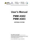
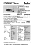
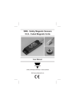
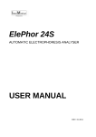
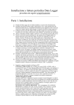
SAFETY RELAY
ND1/2-D
User’s Manual
SAIET Elettronica S.p.A. - A Member of CARLO GAVAZZI Group
via Serenari, 1 - 40013 Castel Maggiore (BO), Italy
Tel. +39 051 4178811 - Fax +39 051 4178800
http://www.saiet.it/elettronica E-mail:[email protected]
Gross Automation (877) 268-3700 · www.carlogavazzisales.com · [email protected]
Index
1. INTRODUCTION..........................................................................3
2. SAFETY INDICATIONS ...............................................................3
3. ASSEMBLY AND FUNCTION......................................................4
3.1 Power supply terminals ........................................................4
3.2 Input terminals ......................................................................4
3.3 Function................................................................................4
4. MOUNTING AND OPENING .......................................................5
5. ELECTRONIC CONNECTION.....................................................6
5.1 Power supply........................................................................6
5.2 Close the feedback control loop and the input circuit. ..........6
5.3 PNP auxiliary output.............................................................6
6. MAINTENANCE AND REPAIR ....................................................7
7. FAULT DIAGNOSIS.....................................................................8
8. WIRING HINTS FOR OUTPUT TERMINALS ..............................8
9. TECHNICAL DATA ......................................................................8
Gross Automation (877) 268-3700 · www.carlogavazzisales.com · [email protected]
1.
INTRODUCTION
This operating instruction is
referred to the two-hand devices
monitoring relay ND1/2-D (24
Vac/dc) and to the models
supplied with an AC power supply
and named ND1/2-D/xxx (where
xxx is the AC supply voltage).
The ND1/2-D name, used in this
manual, is referred to all the
models (DC and AC supply), if not
differently specified.
These instructions are addressed
to the following persons:
• Qualified professionals who
plan and develop safety
equipment for machines and
plants and who are familiar with
the safety instructions and
safety regulations.
• Qualified professionals, who
install safety equipment into
machines and plants and put
them into operation.
The operating instructions
contains several symbols which
are used to highlight important
information.
WARNING
ü This word is placed in front of
text which has to be absolutely
paid attention to.
Nonobservance leads to
serious injuries or damage to
property.
IMPORTANT
ü This word is placed in front of
text which contains important
information.
ACTIVITY
ü This word is placed in front of
activities.
RESULT
ü After this word follows a
description on how the situation
has changed after an activity is
performed.
2.
SAFETY INDICATIONS
Application
The safety relay ND1/2-D can be
used in applications for Two-Hand
control according to EN 574 up to
level IIIc.
IMPORTANT
ü Person and object protection
are not guaranteed, if the safety
relay is not used according to
the defined application.
WARNING
FOR YOUR SAFETY!
Please, note the following points:
ü The unit should only be
installed and operated by
persons who are familiar with
both these instructions and the
current regulations for safety at
work and accident prevention.
Electrical works may be
executed only by electrical
specialist.
ü Follow local regulations as
regards preventative measures.
3
Gross Automation (877) 268-3700 · www.carlogavazzisales.com · [email protected]
ü Starting the machine while
standing in the dangerous area
must be impossible.
ü Any guarantee is void following
opening of the housing or
unauthorized modifications.
ü Avoid mechanical vibrations
greater than 5 g / 33 Hz when
transporting and in operations.
ü The unit should be panel
mounted in an enclosure rated
at IP 54 or better, otherwise
dampness or dust could lead to
function impairment.
ü Adequate fuse protection must
be provided on all output safety
contacts with capacitive and / or
inductive loads.
ASSEMBLY AND
3.
FUNCTION
3.1
Power supply terminals
The supply voltage must be
applied to the terminals A1 and
A2. The POWER LED illuminates.
3.2
Input terminals
The input terminals S11, S12, S21
and S22 have to be wired up to
the two-hand control device as
shown in the connection diagrams
of this user’s manual.
3.3
Function
The unit is enabled to start when
the two switches S1 & S2 are
operated with a delay lower than
0.5 seconds (see Fig. 1). At this
time, the safety outputs 13-14, 2324 and the PNP auxiliary output
34 close immediately, while the
auxiliary contact 31-32 opens
immediately.
The LEDs Channel 1 and
Channel 2 illuminate.
If one or both buttons are
released, the safety outputs 1314, 23-24 and the PNP auxiliary
output 34 open immediately, while
the auxiliary contact 31-32 closes
Fig. 1 - Timings
4
Gross Automation (877)
268-3700 · www.carlogavazzisales.com · [email protected]
Terminal
A1
A2
S11, S12, S22
S21, S12, S22
Y1-Y2
34
13-14
23-24
31-32
Function / Connection
+24VDC or AC supply
GND or AC supply
First input button (S1)
Second input button (S2)
Feedback control loop
PNP aux output (collector of a PNP transistor with emitter
connected internally to Vcc)
First safety output (N.O.)
Second safety output (N.O.)
Relay auxiliary output (N.C.)
Fig. 2 - Functional circuit diagram of ND1/2-D relay
immediately. The LEDs Channel
1 and/or Channel 2 turn off.
A new cycle can be started only
after releasing both S1 & S2
switches and if the feedback
control loop contacts are closed
(external contactors deenergized).
4.
MOUNTING AND
OPENING
The unit should be panel mounted
in an enclosure rated at IP 54 or
better, dust and humidity
protected, because dampness or
dust could lead to function
impairment.
5
Gross Automation (877) 268-3700 · www.carlogavazzisales.com · [email protected]
the technical data of this user’s
manual.
5.
ELECTRONIC
CONNECTION
Fig. 3 - DIN-Rail mounting
ACTIVITY
ü There is a notch on the rear of
the unit for DIN-Rail mounting.
Carry out the wire appropriate to
the use of the unit, according to
5.1
Power supply
Connect the power supply to A1
and A2 terminals.
5.2
Close the feedback
control loop and the
input circuit.
Connect the N.C. Feedback
contacts of the external contactors
to the Y1-Y2 terminals.
Connect the two-hand control
device as shown in Fig. 4
(Connection Diagram)
5.3
PNP auxiliary output
The PNP output is internally
Fig. 4 - ND1/2-D Connection diagram
6
Gross Automation (877)
268-3700 · www.carlogavazzisales.com · [email protected]
Fig. 5 - Connection of the auxiliary PNP output
connected to the +24 Vcc. On
terminal 34 is available the
collector of the PNP transistor.
Connect to the 34 terminal an
external resistive load with
R≥2400 Ohm (see fig. 3).
Connect the ground of the PNP
external circuit to:
• A2 terminal, if the safety relay is
powered with 24 Vdc supply;
• S12 (internal ground) terminal if
the relay is powered with an AC
supply.
WARNING
ü Please, note the maximum
length of the cables!
6.
MAINTENANCE AND
REPAIR
The safety relay ND1/2-D is
maintenance-free.
Fig. 6 - Change of the ND1/2-D safety relay
7
Gross Automation (877) 268-3700 · www.carlogavazzisales.com · [email protected]
In event of failure, it is possible to
change the defective device with
a new one following the steps
described below:
ü Switch off the relay and remove
the wiring from the device.
ü Take off the defective device
from the DIN-Rail.
ü Mount the new device on the
DIN-Rail.
ü Insert and fix the cables on the
new device.
FAULT DIAGNOSIS
7.
Earth Fault (AC/DC version
with electronic fuse protection).
An electronic fuse forces the
output contacts to open. As soon
as the fault cause is removed, and
the rated power supply is applied,
the device is ready for new
operations.
Faulty contact condition
In the event of welded contacts,
further activation is not possible
following the opening of the input
circuit.
Only one or no LED illuminates
External wiring or internal fault is
present.
Check the external wiring and
restart the safety relay.
If the fault is still present, contact
SAIET Elettronica.
8.
WIRING HINTS FOR
OUTPUT TERMINALS
The positive power supply voltage
(for example L or 24 VDC, but not
GND) should be routed via the
output terminals. This will help to
recognize shorts to GND or Earth.
Using R-C combination in parallel
with inductive loads (for example
coils of the external contactors)
can reduce the wearing out of the
output contacts.
TECHNICAL DATA
9.
See the following tables.
8
Gross Automation (877)
268-3700 · www.carlogavazzisales.com · [email protected]
ELECTRICAL DATA
Power supply voltage (Uv)
Voltage range
Frequency (AC Type)
Power Consumption (Approx.)
CONDUCTORS DATA
Conductor connection
Max Conductor Length (input
circuit, cross-section = 1.5 mm2)
Max. capacity of input cables
CONTACTS DATA
Safety Contacts
Aux. Contact
Safety & N.C.Aux.Contact type
Contact Material
Switching voltage
Switching current
Max switching capacity
Mechanical lifetime
Electrical lifetime
Creeping distance and
clearance
(DIN VDE 0160)
(DIN VDE 0110)
Contact security
(DIN VDE 0660 - Part 200)
Voltage at S11 terminal
Delay on de-energization
Max delay between inputs
VALUES
24 VDC (Elec.fuse protect)
or AC supply
0.85 ... 1.1 Uv
50 - 60 Hz
2 VA / 2 W
VALUES
0.14 ÷ 2.5 mm2 Rigid Wire
0.14 ÷ 2.5 mm2 Flexible Wire
4x150 m (@+55°C)
150 nF/km
VALUES
2 N.O.
1 N.C. Relay output
1 N.O. PNP output
Forced Guided Relays
AgSnO2 or comparable
250 VAC , 24 VDC
6A
1500 VA (ohms load)
107 cycles
105 cycles
Pollution degree: 2.
Basis insulation: Overvoltage
Category: 3/250 V
Protective Separation: Ov. Cat. 2
6 A fast or 4 A slow
24 VDC
< 30 ms
0.5 sec.
9
Gross Automation (877) 268-3700 · www.carlogavazzisales.com · [email protected]
AUXILIARY PNP OUTPUT
Supply voltage of the relay
Resistive load
MECHANICAL DATA
Housing Material
Dimensions (WxHxP)
Fastening
ENVIRONMENTAL DATA
Operating Temperature
Max. Humidity
Terminal type (DIN VDE 0470 Part 1)
Housing type (DIN VDE 0470 Part 1)
Shock resistance (DIN VDE 0160)
VALUES
> 18 VDC
≥ 2400 Ohm
VALUES
Polyamid PA6.6
22.5 x 114.5 x 99
Click-fastening for DIN-rail
VALUES
-25°C .... + 55°C
Alt. Cycle: 95% / 0-50 °C
IP 20
IP 40
5g, 33 Hz
10 268-3700 · www.carlogavazzisales.com · [email protected]
Gross Automation (877)
11
Gross Automation (877) 268-3700 · www.carlogavazzisales.com · [email protected]
SAIET reserves the right to make improvements or changes without prior notice.
12 268-3700 · www.carlogavazzisales.com · [email protected]
Gross Automation (877)