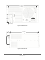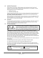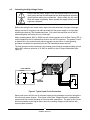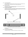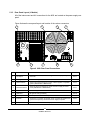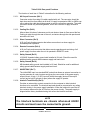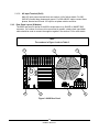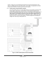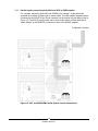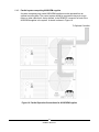
1
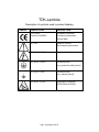
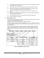
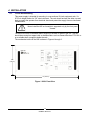
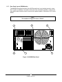
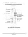
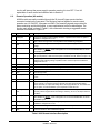
OPERATOR MANUAL FOR 802 Series High Voltage POWER SUPPLY Document: 83488001 Rev L TDK-LAMBDA AMERICAS 405 Essex Road, Neptune, NJ 07753 Tel: (732) 922-9300 Fax: (732) 922-9334 Web: www.us.tdk-lambda.com/hp PAGE LEFT INTENTIONALLY BLANK ONE YEAR WARRANTY TDK-Lambda Americas, Inc. (405 Essex Road, Neptune, N.J. 07753), warrants that the unit is free from defects in material or workmanship for a period of ONE YEAR from the date of initial shipment. TDK-Lambda Americas Inc. will service and, at its option, repair or replace parts which prove to be defective. This will be done free of charge during the stated warranty period. This warranty excludes defects resulting from misuse, unauthorized modification, operation outside the environmental or safety specifications of the power supply, or improper site preparation or maintenance. The customer shall contact TDK-Lambda Americas Inc., for warranty service or repair as described in the RETURNING EQUIPMENT section. The customer shall prepay shipping charges. If the unit is covered under the foregoing warranty, then TDK-Lambda Americas Inc. shall pay the return shipping charges. The “WARRANTY”, “CLAIM FOR DAMAGE IN SHIPMENT”, and “RETURNING EQUIPMENT” information applies to equipment purchased directly from TDK-Lambda Americas Inc. End users receiving equipment from a third party should consult the appropriate service organization for assistance with these issues. THIS LIMITED WARRANTY IS IN LIEU OF, AND TDK-LAMBDA AMERICAS INC. DISCLAIMS AND EXCLUDES, ALL OTHER WARRANTIES, STATUTORY, EXPRESS OR IMPLIED, INCLUDING, WITHOUT LIMITATION, ANY WARRANTY OF MERCHANTABILITY OR FITNESS FOR A PARTICULAR PURPOSE, OR OF CONFORMITY TO MODELS OR SAMPLES. CERTIFICATION All test and measuring equipment used by TDK-Lambda Americas Inc. for Final Acceptance Testing are traceable to primary standards certified by the National Institute of Standards and Technology. LETHAL VOLTAGES PRESENT! All power supplies contain hazardous voltage and energy. The power supply must only be operated by qualified personnel who have read this operator’s manual and are familiar with the operation, hazards and application of the power supply. Proper care and judgment must always be observed. 1. Before connecting input AC power, ensure all covers are in place and securely fastened. Ensure the required safety ground to chassis is installed and sufficient cooling is supplied. 2. Proper grounding from the input AC power is required to reduce the risk of electric shock, and to comply with safety agency and code requirements. 3. Use extreme caution when connecting input AC power. Only apply the input voltage specified on the rating label. 4. Use extreme caution when connecting any high voltage cables. Never handle any output cables when the power supply is operating. 5. After a power supply is switched OFF, its output section will retain a charge which may be lethal. Allow sufficient time for self-discharge before handling anything connected to the output. The discharge time specified in the Safety Notes does NOT include extra time required to discharge the energy stored in the user’s load. 6. When user serviceable fuses are present, always replace fuses with the same type and Volt/Amp rating. 7. Never attempt to operate the power supply in any manner not described in this manual. 8. Never remove DANGER or WARNING labels from the power supply. Replace lost or damaged labels immediately. Contact TDK-Lambda Americas Customer Service for replacement labels. 9. The power supply may be serviced only by TDK-Lambda Americas Inc. factory qualified service personnel. Breaking the warranty seal will void the warranty. Prior to opening the power supply, contact TDK-Lambda Americas Inc. Customer Service for a written Service Waiver and a replacement warranty seal. 83-000-005 Rev F TDK-Lambda MANUFACTURER'S PRODUCT DECLARATION INTENDED PURPOSE (USE) The Power Supplies described by this manual are defined by TDK-Lambda Americas Inc. as a component for use in the composition of an apparatus as defined in Article 1 (1) of the EMC Directive (89/336/EEC). These products, as individual components, do not perform in themselves a direct function for the user of the end product. They are not intended to be placed on the market with a direct function to a final user! As such, the products described by this manual are not subject to the provisions of the EMC Directive (89/336/EEC, with amendment 92/31/EEC). The products described by this manual are intended for incorporation into a final product by a professional assembler. It is the responsibility of the assembler to ensure that the final apparatus or system incorporating our products complies with all relevant EMC standards for that final product. OPERATING ENVIRONMENT The operating environment as defined by TDK-Lambda Americas Inc., for the products described by this manual is stated as follows: The Power Supplies described by this manual are intended for use in a protected industrial environment or in proximity to industrial power installations. These locations are often referred to as industrial locations containing establishments that are not connected to the low voltage public mains network. Industrial locations are characterized by the existence of one or more of the following conditions: 1) industrial, scientific and medical (ISM) apparatus are present; 2) heavy inductive or capacitive loads are frequently switched; 3) currents and associated magnetic fields are high; 4) location supplied by their own transformer. These components are not intended for connection to a public mains network, but are intended to be connected to a power network supplied from a high or medium-voltage transformer dedicated for the supply of an installation feeding manufacturing or similar operations. They are suitable for use in all establishments other than domestic and those directly connected to a low voltage power supply network which supplies buildings used for domestic purposes. Page: 83-000-006 Rev D TDK-Lambda Description of symbols used in product labeling SYMBOL PUBLICATION DESCRIPTION EC Council European Community Directive 93/68/EEC Conformity Assessment Product Mark IEC 348 Attention, consult Accompanying documents IEC 60417-1-5036 Dangerous voltage IEC 60417-1-5019 Protective earth (e.g. power line earth ground) IEC 60417-1-5017 Functional earth (e.g. chassis ground) IEC 60417-1-5134 Electrostatic Discharge (ESD) Sensitive Device Page: 83-000-007 Rev E ELECTRICAL STANDARDS All company primary standards are either certified or are traceable to certification by the National Institute of Standards and Technology. CLAIM FOR DAMAGE IN SHIPMENT This instrument received comprehensive mechanical and electrical inspection before shipment. Immediately upon receipt from the carrier, and before operation, this instrument should be inspected visually for damage caused in shipment. If such inspection reveals damage in any way, a claim should be filed with the carrier. A full report of damage should be obtained by the claim agent and this report should be forwarded to us. We will then provide a disposition of the equipment and arrange for repair or replacement. When referring to this equipment, always include the model and serial numbers. The “WARRANTY”, “CLAIM FOR DAMAGE IN SHIPMENT”, and “RETURNING EQUIPMENT” information applies to equipment purchased directly from TDKLambda Americas Inc. End users receiving equipment from a third party should consult the appropriate service organization for assistance with these issues. RETURNING EQUIPMENT Before returning any equipment to the factory, the following steps shall be taken. 1. Notify TDK-Lambda Americas Inc. at 732-918-6888 or follow the instructions at www.US.TDK-Lambda.com/HP/service.htm. Give a full description of the difficulty including the model and serial number of the unit in question. Upon receipt of this information, we will assign a Return Material Authorization (RMA) number and provide shipping instructions. 2. The customer shall prepay shipping charges. Equipment returned to us must be packed in a manner to reach us without damage. The shipping container must be marked with the RMA number in an area approximate to the shipping label with numbers that are easy to read. All returned units that do not show the RMA number on the outside of the container will be refused. If the equipment is repaired within the warranty agreement, than TDK-Lambda Americas Inc. shall pay for the return shipping to the customer. 3. For non-warranty repairs, we will submit a cost estimate for your approval prior to proceeding. The customer shall pay return shipping charges. MECHANICAL INSTALLATION Most power supplies are heavy and, when rack mounted, they should be supported by rails along the sides of the supply from front to rear. The rails must adequately support the unit and not block airflow. Do not support the power supply from the front panel only. Page: 83-000-011 Rev K Table of Contents 1. 1.1. 1.2. 1.3. 1.4. 1.5. 1.6. 1.7. 1.8. 2. 2.1. 2.2. 2.3. 2.4. 2.5. 2.6. 2.7. 2.8. 2.9. 2.10. 2.11. 2.12. 2.13. 2.14. 2.15. 2.16. 2.17. 2.18. 2.19. 2.20. 2.21. 2.22. 2.23. 2.24. 2.25. 2.26. 2.27. 2.28. 2.29. 3. 3.1. 3.2. 3.3. 3.4. 4. 4.1. 4.2. 4.3. 4.4. GENERAL INFORMATION ................................................................................. 5 User Manual Content .......................................................................................... 5 Introduction ......................................................................................................... 5 802 Overview ...................................................................................................... 6 Capacitor Charging Technology .......................................................................... 6 Continuous DC Operation ................................................................................... 7 Additional Features: ............................................................................................ 7 Safety Precautions .............................................................................................. 7 Model Number Format ........................................................................................ 8 SPECIFICATION ................................................................................................. 9 Average Charging Power .................................................................................... 9 Peak Charging Power ......................................................................................... 9 Average DC Power.............................................................................................. 9 Output Voltage Range ......................................................................................... 9 Polarity ................................................................................................................ 9 HV Output Cable ................................................................................................. 9 HV Insulating Medium ......................................................................................... 9 AC Input Voltage ................................................................................................. 9 AC Input Current ................................................................................................. 9 AC Connector...................................................................................................... 9 AC Line Contactor ............................................................................................... 9 Power Factor ....................................................................................................... 9 Efficiency ............................................................................................................. 9 Front Panel.......................................................................................................... 9 Stability ............................................................................................................... 9 Temperature Coefficient ...................................................................................... 9 Stored Energy ..................................................................................................... 9 Pulse to Pulse Repeatability ................................................................................ 9 Dimensions - inches (mm) ................................................................................... 9 Weight - lbs (kg) .................................................................................................. 9 Ambient Temperature.......................................................................................... 9 Altitude ................................................................................................................ 9 Humidity .............................................................................................................. 9 Protection ............................................................................................................ 9 Remote Control (all models) ................................................................................ 9 Accessories ......................................................................................................... 9 Options.............................................................................................................. 10 Ordering Info ..................................................................................................... 10 Ordering Examples............................................................................................ 10 OUT OF BOX INSPECTION ............................................................................. 11 Visual Inspection ............................................................................................... 11 Electrical Inspection .......................................................................................... 11 Contacting TDK-Lambda Americas Customer Service ...................................... 12 Returning Defective Units .................................................................................. 12 INSTALLATION ................................................................................................. 13 19-Inch Rack Mounting ..................................................................................... 13 Ventilation Requirements .................................................................................. 15 Orientation......................................................................................................... 15 AC Power Connection ....................................................................................... 15 1 83488001 Revision L 4.5. 5. 5.1. 5.2. 5.3. 5.4. 5.5. 5.6. 5.7. 5.8. 5.9. 5.10. 5.11. 5.12. 5.13. 5.14. 5.15. 5.16. 5.17. 5.18. 6. 6.1. 6.2. 6.3. 6.4. 7. Connecting the High Voltage Output ................................................................. 17 CONTROLS, INDICATORS, CONNECTORS ................................................... 19 Front Panel Layout (L Model) ............................................................................ 19 HV ON Push Button (Ref 1) ............................................................................... 20 Status LEDs (Ref 2) .......................................................................................... 20 Local Voltage Set (Ref 3) .................................................................................. 21 Voltage bar graph (Ref 4) .................................................................................. 21 Voltage Display (Ref 5) ..................................................................................... 21 HV OFF Push Button (Ref 6) ............................................................................. 21 Off/Local/Remote Keyswitch (Ref 7) .................................................................. 21 View set push button (Ref 8) ............................................................................. 21 Current bar graph (Ref 9) .................................................................................. 21 Current Display (Ref 10) .................................................................................... 22 Power switch (Ref 11) ....................................................................................... 22 Front Panel Layout (S Model) ............................................................................ 22 Front Panel Layout (OEM Model) ...................................................................... 22 Rear Panel Layout (L Models) ........................................................................... 23 Rear Panel Layout (S Models)........................................................................... 25 Rear Panel Layout (OEM Models) ..................................................................... 26 REMOTE CONTROL CONNECTOR PIN DIAGRAM ........................................ 27 OPERATING INSTRUCTIONS.......................................................................... 29 Local Operation (802L only) .............................................................................. 29 Remote Operation (All models) ......................................................................... 30 Remote Control Sequence ................................................................................ 33 Parallel Operation.............................................................................................. 34 APPLICATION NOTES ..................................................................................... 39 2 83488001 Revision L List of Figures Figure 1. 802L Front View .................................................................................................................. 13 Figure 2. 802L Rear View .................................................................................................................. 14 Figure 3. 802L Side View ................................................................................................................... 14 Figure 4 AC Input Terminal Block ..................................................................................................... 16 Figure 5 Typical Load Circuit Connection.......................................................................................... 17 Figure 6 802L Front Panel Controls and Indicators ........................................................................... 19 Figure 7 Front Panel Controls and Indicators (S Model) .................................................................... 22 Figure 8 802L Rear Panel Connections ............................................................................................ 23 Figure 9 802S Rear Panel................................................................................................................. 25 Figure 10 802OEM Rear Panel ......................................................................................................... 26 Figure 11 Remote Interface Connector and Signals. ......................................................................... 27 Figure 12 Suggested external remote interface circuit. ..................................................................... 31 Figure 13 Typical remote Interface waveforms.................................................................................. 34 Figure 14 802L Parallel System Control Connections. ...................................................................... 35 Figure 15 802L and 802S/OEM Parallel System control Connections. .............................................. 36 Figure 16 Parallel Operation Connections for 802S/OEM Supplies ................................................... 37 List of Tables Table 1 :802 Model Description Format . ............................................................................................. 8 Table 2 Recommended AC Input Cable ............................................................................................. 16 Table 3 Front Panel Controls and Indicator Functions (L Model) ........................................................ 19 Table 4 Front Panel Controls and Indicators (S Model) ...................................................................... 22 Table 5 802L Rear panel Functions ................................................................................................... 24 Table 6 802 Remote Interface Description ........................................................................................ 30 3 83488001 Revision L Notes 4 83488001 Revision L 1. GENERAL INFORMATION 1.1. User Manual Content This User’s Manual contains the operating instructions, installation instructions and specifications for the ALE 802 series high voltage power supply. The instructions refer to standard power supply models, and include checkout, installation, and operation of the 802 series. Suggestions and requirements for connecting AC power, load cables and signal cables are given. Various operating modes and programming modes are described. The model 802 is just one model in a broad family of HV power supplies covering the power range from 500J/sec to 30kJ/sec in a single package, and to 1MW and beyond in parallel systems. For more information please visit our web site at: http://www.us.tdk-lambda.com/hp/product_html/high_volt.htm. NOTE This manual contains information, instructions and diagrams which apply to standard constructions. If special features or modifications have been installed, the instructions specific to that modification are contained in Addenda and take precedence if conflicts exist. Please take care to refer to the correct information for your unit. 1.2. Introduction TDK-Lambda Americas ALE model 802 are state of the art constant current switch mode high voltage power supplies, designed to rapidly and efficiently charge capacitors in laser systems, modulators, pulse forming networks, and a broad range of pulse generator circuits, without the need for a series current limiting resistor. They can also be used in many continuous DC applications including beam power for RF devices such as magnetrons, gyrotrons, klystrons and electron beam loads. The 802 series utilize a high frequency IGBT based series resonant inverter topology which operates as a constant current source. This makes the supply perfect for rapidly charging capacitors which represent a challenging load for conventional HV DC supplies using multiplier designs. The 802 series is available with a choice of three different front panel configurations designed to suit different applications and end uses. All models feature the same comprehensive remote control interface which is detailed in Section 6.2. The 802L Model is fully instrumented with front panel meters displaying output voltage and current, status LEDs, a key switch for OFF, LOCAL or REMOTE operation, HV ON/OFF push-button switches, and a 10 Turn output voltage control. The rear panel features external interlock, inhibit, remote control and slave (parallel operation) control connections. The 802S Model can only be operated by remote control and features only status LEDs and a power switch on the front panel. The "S" Models have been designed to operate as a slave unit to the "L" Models or in systems where local control is not a requirement. The 802OEM features a blank aluminum front panel and can only be operated by remote control. As many 802 supplies as required, can be connected in parallel to provide greater output power. 5 83488001 Revision L 1.3. 802 Overview 1.3.1. Features 1.3.2. Benefits 1.3.3. Lightweight switchmode design. Rack mount chassis configuration. Low stored energy provides greater safety. Constant current design eliminates series current limit resistance in charge circuit. Immunity to external EMI. Applications 1.4. 8kJ/sec capacitor charging power, 8kW in continuous DC applications. Output voltages from 0-1kV to 0-50kV. Rep rates from single shot to kilohertz. Local (L Model) or remote operation with comprehensive control interface. Cost effective blank front panel version for OEM applications. Constant current topology for rapid efficient charging. Parallel operation (master/slave) for high power applications. Compact Air Cooled design. Passive Power Factor Correction reduces RMS current draw. Charging capacitors and capacitor banks. Powering pulse forming networks/modulators. Powering lasers: Excimer, flashlamp pumped dye, Yag, CO2, etc. Continuous power for RF tubes – magnetron, gyrotron, TWT, klystron etc. Electron beam applications. DC power source for pulsed hard-tube and solid state modulators. Capacitor Charging Technology Capacitor charging applications require a power supply designed specifically for the task. The 802 series supplies allow capacitors to be charged in pulse forming networks and modulators in a very fast, efficient and controllable manner. The units are compact high power constant current sources that can linearly and rapidly charge a capacitive load to high voltage. Once the load capacitor is charged to the programmed voltage, the supply will switch over to a voltage regulation mode and maintain the load voltage at the programmed level until it is discharged. The flexible design of the 802 allows the unit to be ordered with (L model) or without (S and OEM model) the front panel controls and meters. Front panel controls are ideal in applications where local control and read backs are necessary, such as R&D, laboratory use and diagnostics. All front panel controls and indicator signals are available at the rear panel remote control connector regardless which panel option (L, S, or OEM) is selected. The unit is self-contained, requiring only AC power and appropriate controls. Several units may be connected in parallel for higher power operation. There is no theoretical limit to the number of units that may be paralleled. Typically one master unit and one or more slave or OEM units may be used to obtain as much output power as necessary. The 802 is also ideally suited to charge reservoir capacitors in resonant charging circuits where high rep rates (several kilohertz) are required, such as in metal vapor lasers or solid-state modulators. 6 83488001 Revision L 1.5. Continuous DC Operation Although the 802 series has been designed for capacitor charging applications, they can also be used as a continuous DC High Power Source for RF tubes such as klystrons, TWTs, or other DC loads such as DC-DC converters. The DC option must be specified when ordering, and the supply will be factory setup and tested with a continuous DC load. When 802 supplies are operated in continuous DC applications it is often necessary to add an external capacitor between the load and ground to improve the ripple performance of the unit. Our online Application Note 505 describes operating capacitor charging supplies in DC applications, and gives guidance in determining the size of any additional external filter capacitance required. App Note 505 can be found at: http://www.us.tdk-lambda.com/hp/pdfs/application%20notes/93008505rC.pdf Consult the factory before connecting parallel units in continuous DC applications. 1.6. Additional Features: 1.7. Internal contactor and fuses for AC disconnect and protection Standard AC power and control connectors Documentation Manual Including Installation, check out, suggested remote interfaces and control circuits 10 ft (3m). Output cable is standard, other lengths are optional. Safety Precautions All 802 power supplies are designed to minimize the risk of fire or shock hazard. This instrument received comprehensive mechanical and electrical inspection prior to shipment. Nevertheless, certain safety precautions must be observed. Only TECHNICALLY QUALIFIED SERVICE PERSONNEL familiar with the principles of electrical safety should operate this supply. The power supply SHOULD NOT BE EXPOSED TO WATER OR MOISTURE OR DUSTY ENVIRONMENTS. Electrical safety must be maintained at all times. Lethal voltages are developed within the power supply's enclosure and at the output cable. Therefore, the cover may not be removed by the user (see Warranty in preamble section for variance). Also, the large capacitors in the supply may store power even after the AC input line is removed. ALLOW AT LEAST 40 SECONDS DISCHARGE TIME between removing the AC input line and opening the cover. ALSO, ALLOW AT LEAST 40 SECONDS between switching the AC power off and switching it on again. 1.7.1. This product is designed for Indoor use. 1.7.2. This product is designed for pollution degree 2. 1.7.3. This product is designed for Transient Overvoltage Category II 1.7.4. Ensure all covers are in place and securely fastened before switching ON the AC power. 1.7.5. Proper grounding from the input AC power is required to reduce the risk of electric shock. Ensure that the AC Protective Earth Ground connection has at least the same gauge wire as the supply leads shown in Table 2. 7 83488001 Revision L 1.7.6. Use extreme caution when connecting AC input power, and never apply the incorrect input voltage, refer to ratings label. 1.7.7. Use extreme caution when connecting the high voltage output cable to the load. 1.7.8. Ensure all load capacitors are completely discharged prior to connection. Never handle the output cable when the power supply is operating. 1.7.9. Never attempt to operate the power supply in any manner not described in this manual. 1.7.10. Never remove DANGER and WARNING labels from the power supply. Replace lost or damaged labels immediately. 1.7.11. The power supply should only be serviced by factory authorized personnel. 1.7.12. No user maintenance is required. 1.8. Model Number Format The model numbering system for the 802 Series power supply includes symbols for features and options. They are separated by dashes. Examples are: 802L-10kV-POS-400VAC and 802S-20kV-POS-DC. The 802 is available with three front panel configurations, the L, S, and OEM. The choice of panel configuration is dependent upon the installation and system requirements. See section 5 for further details. Table 1 shows a partial listing of the model description format for the 802 Power Supply family. For additional options, the customer may contact the Sales Department at TDKLambda Americas. Special options are typically shown as a four-digit suffix to the model number. Table 1 :802 Model Description Format . 8 83488001 Revision L 2. SPECIFICATION 2 2.1. Average Charging Power 8,000 Joules/sec (½CV x Rep Rate) 2.2. Peak Charging Power 9,000 Joules/sec (½CV ∕ tcharge) 2.3. Average DC Power 8,000 Watts 2.4. Output Voltage Range 1, 2, 4, 5, 10, 15, 20, 30, 40, 50kV, variable from 10-100% of rated. Other voltages on request, please contact the factory. 2.5. Polarity Available as fixed Positive or Negative. Please specify at time of ordering 2 1-39kV Models - DS2124 Coaxial cable with proprietary HV connector 2.6. HV Output Cable 40-50kV Models - DS2214 Coaxial cable with proprietary HV connector 2.7. HV Insulating Medium Exxon Mobil Univolt N61B or equivalent insulating oil 2.8. AC Input Voltage 200-240VAC (180-264), 3Ø or 380-440VAC (340-460), 3Ø + N, 50-60Hz Please specify at time of ordering 2.9. AC Input Current 40A for 200-240VAC Input / 25A for 380-440VAC input 2.10. AC Connector UL/CSA approved terminal block. 3Ø + GND for 200-240VAC, 3Ø + N + GND for 380-440VAC 2.11. AC Line Contactor UL/CSA approved AC line contactor (standard on 802L and 802S, option for 802OEM) 2.12. Power Factor Passive PFC pf = 0.85 at full load and nominal AC line 2.13. Efficiency Better than 85% at full load 802L - Voltage Control, Voltage & Current Meters, Status Indicators 2.14. Front Panel 802S - On/Off Switch, Status Indicators 802-OEM - Blank front panel 2.15. Stability 0.2% per hour after 1 hour warmup 2.16. Temperature Coefficient 100ppm per °C typical 2.17. Stored Energy Less than 0.3J all models 2.18. Pulse to Pulse Repeatability ±2% to 1000Hz, consult factory for higher rep rates 2.19. Dimensions - inches (mm) 19 (483) W x 8.75 (222) H x 17 (432) D 2.20. Weight - lbs (kg) 80 (37) 2.21. Ambient Temperature Storage: -20 to +70°C. Operating: -20 to +45°C 2.22. Altitude Storage: 40,000ft (12,000m), Operating: 9,900ft (3,000m) 2.23. Humidity 10-90%, non-condensing 2.24. Protection Open/short circuits, Overloads, Arcs, Overtemp, Overvoltage, Safety Interlock 2.25. Remote Control (all models) Via 25-pin D-sub connector on rear of unit, Signals include, Vprogram (010V), HV Enable/Reset, Inhibit, Summary Fault, Load Fault, Vanalog, Vpeak 2.26. Accessories 10ft HV cable, operating manual 9 83488001 Revision L EN - Low Enable. Replaces standard high enable 5V - 0-5V Analog programming. Replaces standard 0-10V programming. LP - Latching Overload Protection, requires HV reset after overload fault 2.27. Options DC - Continuous DC operation CT - AC line contactor (option for 802-OEM only, standard on 802L and 802S) Double terminated HV cable, and mating bulkhead connector 2.28. Ordering Info Model - XXkV - POS (or NEG) - YYYVAC - ZZ (options) 2.29. Ordering Examples 802L-10kV-POS, 802S-1kV-NEG-DC, 802-OEM-50kV-POS-400VAC All specifications subject to change without notice 10 83488001 Revision L 3. OUT OF BOX INSPECTION 3.1. Visual Inspection Prior to shipment, this instrument was inspected and found to be free of mechanical and electrical defects. As soon as the unit is unpacked, inspect for any damage that may have occurred in transit. Verify the following: a) Check the operation of the front panel control (knob should rotate smoothly). b) Confirm that there are no dents or scratches on the panel surfaces. c) Check front panel meters and LEDs for any broken or cracked lenses. If any damage is found, follow the instructions in Section 3.3. 3.2. Electrical Inspection Before the power supply is installed in a system, verify that no internal damage occurred during shipping. A set of simple preliminary electrical test can be performed if desired. These tests are described below. NOTE The sequences described are for L model supplies with local controls, for S and OEM models the corresponding signals must be applied and monitored through the remote control interface. 3.2.1. Test 1 Purpose: Verify general logic operation, generate maximum output current, and check overload protection circuits. With AC power "OFF" and disconnected, short the HV output by connecting the center conductor of the output cable to its return shield (braid). This dead short will allow the unit to generate full output current at zero voltage. 1. Set the output voltage control to zero. Connect AC power to the unit. Turn "ON" the AC power front panel switch. 2. Turn the front panel keyswitch to the LOCAL position (if applicable). Press the HV "ON" button and turn up the HV control until the power supply is generating output current into the dead short. The current meter will indicate max. current. The voltage meter will read zero and the power supply will intermittently turn on and off indicating the "overload" condition. The unit should continue to indefinitely cycle in this mode with a 1 second period. (The power supply will go into overload when max. current is drawn for more than half a second). If the LP option is installed, the unit will shut down and indicate a fault after delivering full current for 500milliS. 3. Turn off the HV and AC power switches. This test indicates the inverter section is generating maximum current and the logic and overload circuitry works correctly. 3.2.2. Test 2 Purpose: Verify that the power supply generates maximum rated voltage, and the regulation and feedback circuits are functioning. 1. With AC power OFF and disconnected, connect an appropriate load capacitor to the power supply output cable. Select the capacitor size so the charge time is several milliseconds or more. 2. Prepare to charge the capacitor. NOTE: Operating a 802 power supply into an open circuit (no load operation) will instantly damage the power supply's HV output 11 83488001 Revision L diodes. Make sure the load (capacitor) is connected and the HV output cable is securely inserted and connected. 3. Turn the voltage control on the front panel all the way down to zero (counter clockwise), apply AC power, turn the front panel keyswitch to the LOCAL position (if applicable), and press the HV ON button. By turning up the HV control knob the capacitor will charge to the voltage indicated on the front panel voltmeter. The power supply may be turned all the way up to its max. output voltage provided the load capacitor is sufficiently rated. 4. By turning the voltage control down or depressing the HV OFF button, the capacitor will slowly "bleed" down through the internal voltage divider resistors used for regulation feedback. Use an external discharge wand to ensure the capacitor is fully discharged. Test #2 indicates the HV section is working correctly. Tests 1 and 2 generally indicate the unit is functioning as designed. Although 100% power had not been generated, these two tests give greater than 90% confidence that the unit is not damaged. If any inconsistency from the above test procedure is noted, do not hesitate to call TDKLambda Americas Customer Service for assistance. 3.3. Contacting TDK-Lambda Americas Customer Service When contacting customer service locate the product description, part number and serial number from the label located on the rear of the unit, and have this information available. Phone: (732) 922-9300 Fax: (732) 922-1441 E-mail: [email protected] Customer Service, or an approved Service Center, should be contacted if: The power supply is mechanically or electrically damaged. The power supply requires on-site calibration, or replacement warning decals. The customer has questions about a special application that is not described in this manual. Normally, the customer may NOT open any chassis covers that have a warranty seal. Breaking a seal will void the warranty. At the discretion of TDK-Lambda Americas, the customer may be granted permission to break the warranty seal and open the chassis covers. Customer Service shall confirm the permission by sending a replacement seal. Once the unit has been serviced, the customer shall close the cover and apply the replacement seal adjacent to (not on top of) the broken seal. 3.4. Returning Defective Units If a unit needs to be returned to the factory for repair, the factory must first assign an RMA number. Please complete and send the online RMA request form at http://www.us.tdklambda.com/hp/RMA_request.htm and an RMA number will be assigned. Follow the return instructions on the form or at http://www.us.tdk-lambda.com/hp/returns.htm. 12 83488001 Revision L 4. INSTALLATION 4.1. 19-Inch Rack Mounting This power supply is intended for mounting in a conventional 19-inch equipment rack. It’s 8.75 inch height makes it a “5U” size instrument. The rack should enclose the sides, top and back to protect the operator from electrical shock and protect the supply from environmental contamination. Never install the 802 so its weight is supported only by the front panel screws! The 802 must never be installed without support in the back or sides of the unit. The 802 should be mounted on support rails or chassis slides –such as General Devices CTS-124- or on a suitable shelf or supports inside the rack. The mechanical outline of the 802 is shown in Figures1 through 3. 8.72” (222mm) 19” (483mm) Figure 1. 802L Front View 13 83488001 Revision L 19” (483mm) 17” (432mm) 4.5” (114mm) 2.15” (55mm) Figure 2. 802L Rear View 1.875” (48mm) 17” (432mm) Figure 3. 802L Side View 14 83488001 Revision L 4.2. Ventilation Requirements This instrument is fan cooled. Sufficient space must be allocated so that a free flow of cooling air can reach the back and sides of the instrument when it is in operation. Ensure these clearances are met for adequate air flow: 4 inches (10 cm) rear 1 inch (2.5 cm) on each side. Cooling air exits through the rear of the unit, and enters through the side panels and around the HV tank. This power supply should not be operated with its cover removed since the cover directs the flow from the internal fan. When operating in an enclosed system, care must be taken to ensure the ambient inlet air to the power supply does not exceed the maximum operating temperature of 45°C. This may require addition of a system heat exchanger. 4.3. Orientation The power supply must be operated in a level horizontal orientation. More than a quarter of an inch (6.25mm) difference in height in any direction could potentially cause an arcing condition in the high voltage tank and should be avoided. 4.4. AC Power Connection For 200-240VAC models, the maximum voltage allowed between any two AC input terminals is 264VAC. For 380-440VAC models, the maximum voltage allowed between any two AC input terminals is 460VAC. If this voltage is exceeded, catastrophic damage will result, that is not covered by TDK-Lambda Americas standard warranty. The customer’s AC power line connects to the 802 via a UL/CSA approved 5 position terminal block on the rear panel of the unit (see Figure 1). Only use a power cable with the correct voltage and current rating (see Table 2). The ground wire must be equal to or larger than the recommended gauge. Secure grounding of the input AC power is required to reduce the risk of electric shock. The metal chassis of the power supply is grounded through the earth wire at the input AC power terminal block. Use extreme caution when connecting input AC power and never apply the incorrect input power. An external switch or circuit breaker with the following parameters must be used as means of disconnection: a) Rated voltage not less than maximum rated voltage of the power supply b) Rated current not less than 150% of the power supply rated current The switch or circuit breaker must be located in proximity to the power supply and within easy access of the operator. The switch or circuit breaker must be marked as disconnecting device for the equipment. The Protective Earth Ground must be connected before applying AC Line Power to the 802. 15 83488001 Revision L Connect the three lines of the input power to the L1, L2, L3 terminals and the earth ground to the terminal marked with the ground symbol ( ). No neutral connection is required for the 200-240VAC configuration. For models with the 380-440VAC input configuration (340460VAC) the neutral wire must be connected to terminal marked N. The power connections are not phase rotation sensitive, so any phase can be connected to any of the AC inputs. Figure 4 AC Input Terminal Block If the power supply was purchased with the 400VAC input configuration, in addition to the three phases, the neutral wire must be connected to terminal marked N. Failure to connect the Neutral wire in a 400VAC unit may result in damage to the supply. AC INPUT VOLTAGE MODE RECCOMENDED AC INPUT CABLE SIZE & RATING 200-240VAC (180-264VAC), 50-60 Hz, 3 Cap Charging Continuous DC Cap Charging Continuous DC 9mm /8 AWG, 600V 2 9mm /8 AWG, 600V 2 6mm /10 AWG, 600V 2 6mm /10 AWG, 600V 380-440VAC (340-460VAC), 50-60 Hz, 3 2 Table 2 Recommended AC Input Cable The AC input rating is marked on the rear terminal of the power supply. The rating is also part of the unit’s model description shown in Table 1. 16 83488001 Revision L 4.5. Connecting the High Voltage Output Ensure that the power supply is off and disconnected from the AC input power and that all load capacitors are discharged and shorted to ground before making any connections. Never handle the HV cable while the supply is operating. Never operate the supply without a load capacitor connected. Before connecting the HV output cable, inspect the cable and check for signs of damage. Always use the HV connector and cable provided with the power supply or an equivalent substitute provided by TDK-Lambda Americas. Fully insert the connector end of the HV cable and tighten the locking nut only "hand tight". When operating above 20kV or 200Hz rep rate, silicone grease (such as Dow Corning DC-4) must be applied to the HV cable before insertion into the HV connector. The grease is used to displace air in the connector and reduce long-term corona effects. A cable greasing procedure is available for download from the TDK-Lambda Americas web site. The load ground must be connected to the chassis ground through a separate safety ground cable with a minimum wire size of 10 AWG in addition to the HV output cable shield (see Figure 5). LOAD CIRCUIT ! HV Switch L1 L2 L3 N 3 AC POWER SAFETY GROUND N C B A Figure 5 Typical Load Circuit Connection Some peak current will flow out of the power supply during discharge and return through the HV return and system chassis. This current comes from voltage reversal in underdamped systems and from normal discharge of filter and cable capacitance. The path for this current should not parallel control signal returns since the resulting voltages could interfere with normal system operation. 17 83488001 Revision L Currents due to voltage reversal, particularly at high repetition rates can damage the power supply. Generally, a resistor in series with the HV output can be added to limit this current to an acceptable level, but an additional clamp diode may also be required. Refer to Application Note 517 (available from the factory or at http://www.us.tdk-lambda.com/hp/product_html/high_volt.htm) for more detailed information. Dress the high voltage cable to create a gentle curve ensuring there are no sharp bends as this will tend to reduce the cable's insulation strength. Strain relieve the load end of the high voltage cable to prevent breaking of, or damage to the center conductor. Keep the HV cables as distant as possible from the input power and the control signals. To connect the HV cable to the load it is necessary to remove the cable jacket, shield, and any semiconducting layer (if applicable) that remains on the cable insulation after removing the shield. The cable outer jacket should be removed to reveal the cable shield. At least 12” or 300mm of outer jacket should be removed for suitable voltage hold-off. The exposed shield should be trimmed to an appropriate length and terminated with a ground connection. For models shipped with DS2214 HV cable (>40kV rated voltage), after the shield is removed, the black semiconducting layer is exposed. This layer should be very carefully removed using a sharp craft knife, and a peeling action. Once the semiconducting layer is removed, the exposed EPR insulation should be cleaned with IPA or an equivalent solvent. If any of the semiconducting layer remains on the HV cable insulation it may cause the cable termination to fail. For models shipped with the DS2124 HV cable (<40kV rated voltage), there is no semiconducting layer to be removed from the cable insulation, however the exposed polythene cable insulation should be cleaned with IPA. 18 83488001 Revision L 5. CONTROLS, INDICATORS, CONNECTORS 5.1. Front Panel Layout (L Model) The 802L series power supply is equipped with a fully instrumented front panel featuring output voltage control, voltage and current metering, and comprehensive status LEDs, along with local/remote mode keyswitch, and power on switch. The 802L can be operated locally from the front panel or remotely via the control connector located on the rear panel (see Section 6.2). Front panel layout of the 802L power supply is shown in Figure 3 below. 1 2 6 3 7 4 8 9 5 10 11 Figure 6 802L Front Panel Controls and Indicators REF DESCRIPTION NOTE SECTION 1 HV ON Push Button Turns on HV output 5.2 2 Status LEDs Indicates status of supply and presence of any faults 5.3 3 Local Voltage Set 10 turn pot for setting output voltage in local mode 5.4 4 Voltage bar graph Analog bar graph showing output voltage (%) 5.5 5 Voltage Display Digital display of output or set voltage 5.6 6 HV OFF Push Button Turn off HV output 5.7 7 Off/Local/Remote Key Switches control between remote, local, and off modes 5.8 8 View set push button Push to view the output voltage set point in local mode 5.9 9 Current bar graph Analog bar graph showing average output current (%) 5.10 10 Current Display Digital display of average output current 5.11 11 Power switch Turns on/off power to auxiliary circuits 5.12 Table 3 Front Panel Controls and Indicator Functions (L Model) The front panel controls/indicators are described in detail in the following sections. 19 83488001 Revision L 5.2. HV ON Push Button (Ref 1) DO NOT DEPRESS THE HV ON PUSH-BUTTON UNLESS A SUITABLE CAPACITIVE LOAD IS CONNECTED TO THE POWER SUPPLY'S OUTPUT CABLE, AND THE LOAD IS CORRECTLY GROUNDED. The HV ON push button is a momentary switch that when depressed turns on HV output in local mode (keyswitch in local position) only if there are no faults present within the supply. If faults are present when the HV ON button is pushed the supply will not turn on, and both the HV ON and HV OFF LEDs will illuminate. When both the HV ON and HV OFF LEDS are illuminated together this indicates a Summary Fault. If the keyswitch is in the remote position the HV ON push button has no function. 5.3. Status LEDs (Ref 2) There are 6 status LEDs on the front panel, indicating the state of the HV Output circuit and various fault detection circuits in the control system. 5.3.1. HV ON LED The HV ON LED indicates that the HV output circuit is enabled and the supply will deliver output current if it is not inhibited by an external inhibit input. If the HV ON and HV OFF LEDs are illuminated together this indicates a Summary Fault. HV ON LED is active in local and remote modes. 5.3.2. HV OFF LED The HV OFF LED indicates that the HV output circuit is disabled and the supply cannot deliver output current. If the HV OFF and HV ON LEDs are illuminated together this indicates a Summary Fault. HV OFF LED is active in local and remote modes. 5.3.3. Inhibit LED If the Inhibit LED is illuminated it indicates the presence of an active inhibit signal, and the supply will not deliver charging current after the HV ON button is pushed. Inhibit is applied either via the rear panel mounted BNC connector or either inhibit input via the remote control connector. Inhibit LED is active in local and remote modes. 5.3.4. END OF CHARGE LED The END OF CHARGE or EOC LED indicates that the load or output voltage has reached the programmed voltage. EOC LED is active in local and remote modes. 5.3.5. Interlock Open LED The interlock open LED illuminates if the safety interlock circuit is not closed. The power supply cannot be turned on if the interlock loop is open. If the interlock loop is opened when the unit is running (ie when HV in ON), the unit will turn off with a latching fault, requiring an HV ON/OFF/ON reset cycle before it can be restarted. Interlock Open LED is active in local and remote modes. 5.3.6. Load Fault LED The load fault LED indicates the presence of a fault in the load circuit due to a short circuit large external capacitor, or an output Overvoltage. An output Overvoltage condition will cause a latching fault requiring an HV ON/OFF/ON reset cycle before it can be restarted. Load Fault LED is active in local and remote modes. 20 83488001 Revision L 5.3.7. Overtemp LED The overtemp LED indicates an inverter overtemperature condition internal to the supply. The temp fault will clear once the temperature is below the fault threshold, but the unit will not restart without a reset cycle. Overtemp LED is active in local and remote modes. 5.4. Local Voltage Set (Ref 3) The local voltage set control is an analog 10-turn potentiometer for adjusting the output voltage from zero to full rated output. This control will only operate in local mode. If the supply is operated in remote mode the local voltage set control has no effect. 5.5. Voltage bar graph (Ref 4) The voltage bar graph is a 'quick view' analog percentage indication of the voltage measured at the power supply output. Bar graph is active in local and remote modes. 5.6. Voltage Display (Ref 5) The Voltage Display is a 4 digit LED indicator showing the voltage measured at the power supply output. This display momentarily shows the output program voltage after the View Set button is depressed. Voltage Display is active in local and remote modes. 5.7. HV OFF Push Button (Ref 6) The HV OFF push button is a momentary switch that when depressed turns off HV output. If the power supply shuts off with a summary fault (indicated by HV ON and HV OFF LEDs both illuminated), then this condition can be reset by pushing the HV OFF, HV ON, HV OFF button sequence. If the supply is operated in remote mode the HV OFF push button will still function. 5.8. Off/Local/Remote Keyswitch (Ref 7) DO NOT MOVE THE KEYSWITCH POSITION FROM OFF TO LOCAL OR REMOTE UNLESS A SUITABLE CAPACITIVE LOAD IS CONNECTED TO THE POWER SUPPLY'S OUTPUT CABLE, AND THE LOAD IS CORRECTLY GROUNDED. The Off/Local/Remote Keyswitch switches the 802L power supply operating modes between OFF, LOCAL, and REMOTE. The key can be removed in the OFF position to prevent unauthorized use. If the switch is in the LOCAL position the supply will operate from the front panel. In the REMOTE position the supply can only be operated via the remote control interface. An L model supply can simulate an S or OEM model with the key in the REMOTE position. 5.9. View set push button (Ref 8) The view set push button changes the reading on the digital voltage display from the power supply output voltage, to the programmed voltage set on the local voltage set potentiometer. After pushing this button the set voltage is displayed for approximately 3 seconds. 5.10. Current bar graph (Ref 9) The current bar graph is a 'quick view' analog percentage indication of the average current delivered by the supply. Bar graph is active in local and remote modes. 21 83488001 Revision L 5.11. Current Display (Ref 10) The Current Display is a 4 digit LED indicator showing the average current delivered by the power supply output. Current display is active in local and remote modes. 5.12. Power switch (Ref 11) The power switch connects AC input power to the control circuitry and causes the internal AC contactor to close if the interlock loop is closed. 5.13. Front Panel Layout (S Model) The 802S series power supply is equipped with a partially instrumented front panel featuring status LEDs, and a power on switch. The 802S can only be operated remotely via the control connector located on the rear panel (see Section 6.2). 2 11 Figure 7 Front Panel Controls and Indicators (S Model) REF DESCRIPTION NOTE SECTION 2 Status LEDs Indicates status of supply and presence of any faults 5.3 11 Power switch Turns on/off power to auxiliary circuits 5.12 Table 4 Front Panel Controls and Indicators (S Model) A description of the function of the LEDs and the power switch are given in sections 5.3 and 5.12 respectively. 5.14. Front Panel Layout (OEM Model) The 802OEM front panel is completely blank and features no indicators or switches. 22 83488001 Revision L 5.15. Rear Panel Layout (L Models) All of the interconnect and HV connections for the 802L are located on the power supply rear panel. Figure 8 shows the rear panel layout and location of the various connectors. 1 2 3 4 ! L1 5 6 7 L2 L3 N 8 9 Figure 8 802L Rear Panel Connections REF DESCRIPTION NOTE SECTION 1 HV Output HV Output connector, mates with supplied cable via proprietary connector 5.15.1 2 Cooling fan Main AC cooling fan. Leave at least 4" clearance 5.15.2 3 Slave Interface 25pin male sub-D type plug for control of slave supplies in a parallel system (AMPHENOL 17BDFRA25P) 5.15.3 4 Remote Interface 25pin sub-D type receptacle for remote control of supply in remote mode (AMPHENOL 17BDFRA25S) 5.15.4 5 GND stud 10-32 UNC ground stud 5.15.5 6 GND stud M5 ground stud (2 positions) 5.15.6 7 Inhibit input BNC input to allow inhibit of output current 5.15.7 8 Interlock Terminal for connection to interlock circuit. Contacts are isolated from ground and require dry contact closure for supply to operate. 5.15.8 9 AC Input 5 position terminal block for AC input power 5.15.9 23 83488001 Revision L Table 5 802L Rear panel Functions The function of each item in Table 5 is described in the following sections. 5.15.1. HV Output Connector (Ref 1) Connector socket for mating HV cable supplied with unit. The connector should be kept clean and free from debris at all times. If supply is operated at 20kV or 200Hz rep rate or above the cable should be greased to ensure corona free operation. The cable connector should only be hand tightened, never use a wrench or apply excessive force. 5.15.2. Cooling Fan (Ref 2) Allow at least 4 inches of clearance and do not obstruct clear air flow around the fan. Cooling air exits through the rear of the unit, and enters through the side panels and around the HV tank. 5.15.3. Slave Connector (Ref 3) A 25 pin D-sub female connector that allows connection to a slave supply for increased power operation. 5.15.4. Remote Connector (Ref 4) A 25 pin D-sub male connector that allows remote operation and monitoring of all power supply functions when the unit is operated in REMOTE mode. 5.15.5. Safety Ground (Ref 5) 10-32UNC threaded safety ground stud installed in HV tank. Should be used for additional safety ground cable between supply and load circuit. 5.15.6. Safety Ground (Ref 6) M5 threaded safety ground stud installed in HV tank. Should be used for additional safety ground cable between supply and load circuit. 5.15.7. INHIBIT BNC (Ref 7) The inhibit BNC input is a standard BNC socket that allows an external connection to a pulse generator or control system and gives the user control of the power supply output current. A logic 1 (5-15V) input will inhibit the supply (shuts off the output current) and a logic 0 (ground or open) allows the supply to operate. 5.15.8. Interlock Terminal strip (Ref 8) Provides an external dry contact connection for the customer to allow interlock functions to be controlled. The interlock terminals should be connected to any safety interlock circuitry in the power supply installation. When the interlock is open the AC line contactor disconnects the AC line from the power circuitry. The power supply is shipped with a factory installed shorting link across the interlock terminals. NOTE The Interlock terminals are chassis referenced 24VAC circuits and must never be connected to ground. 24 83488001 Revision L 5.15.9. AC Input Terminal (Ref 9) Main AC input power terminal block see section 4.4 for further details. For 200240VAC connect three phases and ground. For 380-440VAC option connect three phases, Neutral and Ground. AC input is not phase rotation sensitive. 5.16. Rear Panel Layout (S Models) The 802S rear panel is similar to the 802L except these is no SLAVE or INHIBIT BNC connector. If a number of units are to be connected in parallel, a daisy chain type ribbon cable should be used to connect the supplies together. See section 6.4 for more details. Note: The numbers in Figure 9 refer to Table 5. 1 2 4 ! L1 5 6 8 Figure 9 802S Rear Panel 25 83488001 Revision L L2 L3 N 9 5.17. Rear Panel Layout (OEM Models) The 802OEM rear panel is similar to the 802S except there is no interlock terminal, unless the CT option is installed. If a number of units are to be connected in parallel, a daisy chain type ribbon cable should be used to connect the supplies together. See section 6.4 for more details. Note: The numbers in Figure 10 refer to Table 5. 1 2 4 ! L1 5 6 L2 L3 N 9 Figure 10 802OEM Rear Panel 26 83488001 Revision L 5.18. REMOTE CONTROL CONNECTOR PIN DIAGRAM Figure 11 shows a summary of the remote control signals on the connector labeled 4 in Figure 5 through 8. The connector is a 25-pin sub D-type receptacle (female). Pin 1. Analog Out Pin 14. +15V Pin 3. Inhibit LED Pin 16. Overtemp LED Pin 17. Interlock LED Pin 5. End of Charge LED Pin 18. Load fault LED Pin 19. Summary fault LED Pin 7. Inhibit Input Pin 20. Inhibit Input Pin 8. HV On/Off Pin 9. Peak output volts Pin 22. Vprogram input Pin 10. HV On LED Pin 23. HV Off LED Pin 24. GND Pin 12. GND Pin 13. Charge current Figure 11 Remote Interface Connector and Signals. 27 83488001 Revision L Notes 28 83488001 Revision L 6. OPERATING INSTRUCTIONS The 802 power supply is designed for operation in two modes. The first mode is local, where the power supply can be controlled from the front panel. Local operation is only possible with the L model supply. The second mode is remote, where control signals are passed via the 25pin remote connector. Remote operation is possible with all 802 model power supplies (L, S, or OEM). 6.1. Local Operation (802L only) The model 802L has full front panel instrumentation and controls for use in laboratory, prototype or OEM systems. The front panel controls include power on/off, remote/local and HV on/off switches, output voltage adjust, view set switch, digital voltage and current meters, quick reference bar graphs and status indicators. An internal AC contactor is included which is controlled by the front panel power switch and the interlock terminals located on the rear of the unit. A BNC connector is provided on the rear panel for easily connecting a pulsed INHIBIT signal when operating from the front panel. The model 802L can be operated as a "master" unit in parallel with several model 802S or OEM "slave" units for increased output power. Refer to Section 6.4 "Paralleling Units". Before operating the power supply ensure a load capacitor is connected between the power supply output, and the other terminal of the capacitor is connected to ground or the appropriate point in the load circuit. Failure to correctly connect a capacitive load prior to operating the power supply may result in damage. HIGH VOLTAGES MAY POTENTIALLY EXIST FROM THIS POINT FORWARD. The power supply should be connected to 3 phase AC power as described in section 4.4. The interlock terminals should be closed either with the supplied shorting link or by an isolated external dry contact. Follow the steps below; 1. Ensure the output voltage potentiometer is turned fully counter clockwise. 2. Turn on the AC power switch, the cooling fan should start and the front panel indicators will illuminate. 3. Turn the control key to the local position. 4. Push the View Set button and turn the Voltage potentiometer until the required load voltage is displayed. The view set mode stays active for approximately 3 seconds before the voltage display reverts to the output voltage mode. 5. Push the HV ON button. The load will charge to the preset voltage and once this voltage is reached the End of Charge LED will illuminate. The supply will maintain this voltage until the HV OFF button is pushed, or the load capacitor is discharged via the HV switch in the load circuit. After the load has been discharged the external Inhibit function can be used to shut down the power supply output current which aids in the HV switch recovery. Application of an inhibit signal will typically shut down the output current in approximately 15microseconds. To turn OFF the power supply depress the HV OFF button, or use the Inhibit input to shut off the output current but leave the supply in the HV ON condition. Opening the interlock terminals will also cause the power supply to turn off. In this case the unit can only be turned back on after the interlock has been closed and the HV ON button depressed followed by the HV OFF button to RESET the fault. Any other fault occurring in the internal protection 29 83488001 Revision L circuitry will interrupt the power supply's operation causing it to turn OFF. For a full explanation of each control and indicator refer to Section 5. 6.2. Remote Operation (All models) All 802 models are easily controlled through the 25 pin sub D-type remote interface connector located on the rear panel. The minimum required signals for remote control operation are; HV ON/OFF, Vprogram and GND. The remaining signals are provided for status monitoring and fault diagnosis, or more sophisticated control methodologies. The function each signal is shown in Table 6, with a schematic showing a suggested remote interface circuit shown in Figure 12. Pin Signal Name I/O Description 1 Analog Out O 0-10V (±1%) Analog of output voltage waveform. Impedance 1kIf the 5V option is installed the voltage level is 0-5V. 3 Inhibit LED O Open collector through 100. Low impedance when INHIBIT signal applied. 5 End of Charge LED O Open collector through 100. Low impedance when power supply reaches End of Charge. 7 Inhibit Input I 5-15V Inhibits unit, open or ground allows operation. Input impedance >10kNote use either INHIBIT or INHIBIT, never both signals. Do not use the INHIBIT BNC as well as the INHIBIT signal. 8 HV ON/OFF I 15V=On, ground or open =Off. Also used to reset latching faults by cycling from On to Off. Input impedance >1M If the EN option is installed 15V=Off, Ground or open = On 9 Peak output volts O 0-10V (±1%) Peak detector of output voltage waveform. Can be used to drive a meter displaying peak charging voltage. Impedance 10k. If the 5V option is installed the voltage level is 0-5V. 10 HV ON LED O Open collector through 100. Low impedance when HV output is enabled. 12 GND 13 Charge current O Uncalibrated Analog of output current waveform. Impedance 10k 14 +15V O +15V through 100 16 Overtemp LED O Open collector through 100. Low impedance when inverter overtemperature condition occurs. 17 Interlock LED O Open collector through 100. Low impedance when external interlock circuit is open. 18 Load fault LED O Open collector through 100. Low impedance when load fault condition occurs. Load fault is normally a non-latching fault and will self-reset after approximately 500ms, unless caused by an output overvoltage where the supply will latch off. For models with the LP option, an external RESET cycle is required to restart the unit. 19 Summary Fault LED O Open collector through 100. Low impedance indicated a summary fault condition. Summary fault is a logical OR of Overvoltage, Overtemp, AC Line, and Open Interlock conditions. 20 Inhibit Input I 0V Inhibits unit, 15V or open allows operation. Input impedance >10 kNote use either INHIBIT or INHIBIT, never both signals. Do not use the INHIBIT BNC as well as the INHIBIT signal. 22 Vprogram I 0-10V = 0-100% of rated output voltage. Input impedance >1M. If the 5V option is installed the voltage level is 0-5V. 23 HV OFF LED O Open collector through 100. Low impedance when HV output is off/disabled. 24 GND Control circuit return. Also chassis/earth ground. Control circuit return. Also chassis/earth ground. Table 6 802 Remote Interface Description 30 83488001 Revision L Figure 12 Suggested external remote interface circuit. A detailed description of each remote control signal is given in the following sub-sections. 6.2.1. Analog Out Pin 1. Analog of output voltage waveform as measured at the output terminals of the power supply. Signal is 0-10V +/-1% (0-5V if 5V option installed). 6.2.2. Inhibit LED Pin 3. Open collector Active Low output indicating presence of an external Inhibit signal. Max rated voltage - 60V, 100Ω series resistance. 31 83488001 Revision L 6.2.3. End Of Charge (EOC) LED Pin 5. Open collector Active Low output indicating power supply output voltage has reached the programmed voltage or end of charge cycle. Max rated voltage - 60V, 100Ω series resistance. 6.2.4. Inhibit Input Pin 7. 5-15V Inhibits unit (turns off output current), open or ground allows operation. Input impedance >10kΩ. Signal can be used to aid load switch recovery. 6.2.5. HV ON/OFF Pin 8. +15V = HV ON, ground or open = HV OFF. Also used to reset latching faults by cycling from ON to OFF. Input impedance > 1MΩ. If EN option is installed +15V = OFF, Open or Ground = ON. 6.2.6. Peak Output Volts Pin 9. Peak detector of Analog output voltage waveform. Can be used to drive a meter displaying peak charging voltage. Signal is 0-10V +/-1% (0-5V if 5V option installed). 6.2.7. HV ON LED Pin 10. Open collector Active Low output indicating power supply output is ON/Enabled. Max rated voltage - 60V, 100Ω series resistance. If the HV ON and HV OFF signals are both active at the same time, this indicates a Summary Fault. 6.2.8. Ground Pin 12. Control circuit return. Also chassis/earth ground. 6.2.9. Charge current Pin 13. Analog of output current waveform. Signal is not calibrated. 6.2.10. +15V Output Pin 14. +15V through 100Ω, maximum current is 20mA. 6.2.11. Overtemp LED Pin 16. Open collector Active Low output indicating an inverter overtemperature condition has occurred. Once temperature has returned to normal levels this fault will clear, but the power supply will not restart without a Reset Cycle. Max rated voltage 60V, 100Ω series resistance. 6.2.12. Interlock LED Pin 17. Open collector Active Low output indicating the external interlock circuit is open. Max rated voltage - 60V, 100Ω series resistance. 6.2.13. Load Fault LED Pin 18. Open collector Active Low output indicating a load fault condition. Load fault is a non-latching fault and will self-reset after approximately 500ms (for models without LP option). Load fault is caused by an output overvoltage condition (110% of rated voltage) or an output short circuit/large capacitor (load charges for 500ms without reaching programmed voltage). Max rated voltage - 60V, 100Ω series resistance. 32 83488001 Revision L 6.2.14. Summary Fault LED Pin 19. Open collector Active Low output indicating a summary fault condition. Summary fault is a logical OR of Overvoltage, Overtemp, AC Line, and Open Interlock conditions. Summary Fault is also indicated by both HV ON and HV OFF LEDs/indicators being illuminated at the same time. Max rated voltage - 60V, 100Ω series resistance. 6.2.15. Not Inhibit Input Pin 20. Logical Inverse of Inhibit input (Pin 7), 0V Inhibits unit, 15V or open allows operation. User should control supply with either the Inhibit or Not Inhibit signal, both signals should not be used together. Input impedance >10kΩ. 6.2.16. Vprogram Pin 22. 0-10V Analog Input = 0-100% of rated output voltage (0-5V if 5V option is installed). Input impedance >1MΩ. 6.2.17. HV Off LED Pin 23. Open collector Active Low output indicating HV output is off/disabled. Max rated voltage - 60V, 100Ω series resistance. 6.2.18. Ground Pin 24. Control circuit return. Also chassis/earth ground. 6.3. Remote Control Sequence Note The logic levels in the description below are for a supply without EN option. If EN is installed the logic levels for HV ON/OFF should be reversed. Before operating either an 802L, S, or OEM in remote mode it must first be connected to a master supply, or an appropriate external control system. To operate a model 802L in remote mode the front panel keyswitch must be in the REMOTE position. It is suggested that the INHIBIT signal is used in addition to the HV ON/OFF signal to control the output current of the power supply during the normal charge/discharge cycle. The INHIBIT signal should be asserted (Pin 7=5-15V) prior to activating the HV ON signal. Do not connect the INHIBIT BNC and the Inhibit signal on the remote interface, only the remote interface should be used in remote mode. Once HV ON has been set (Pin 8=15V), then INHIBIT can be removed (Pin 7=0V), and the supply will begin charging the load. A few tens of microseconds before the load switch is triggered to close, the INHIBIT signal should be asserted to turn-off the output current, and aid in switch recovery. After the load is discharged, and the HV switch has recovered to an insulating state, INHIBIT can be removed and the load re-charged. A typical set of remote control waveforms illustrating this sequence is shown in Figure 13. There is no need to turn HV ON and OFF during the normal charge/discharge cycle, just use the INHIBIT signal to control the power supply. HV should be turned off (Pin 8=0V) as soon as the load circuit is no longer required to operate. 33 83488001 Revision L 15V HV ON/OFF 0V 10V VANALOG 0V 15V INHIBIT 0V Figure 13 Typical remote Interface waveforms The 802 supply can also be controlled without using the Inhibit signal (leaving Pin 7or 20 unconnected), and in this case the output current is immediately turned ON when the HV ON signal is activated assuming there are no faults present. 6.4. Parallel Operation The 802 series capacitor charging power supplies are constant current sources, and can simply be connected in parallel for applications requiring increased power. Parallel supplies should have the same output voltage rating and programming options (if one unit has the 5V option, all others in parallel must have this option). Note that it is also possible to operate power supplies in parallel from different series (ie a model 802 in parallel with a model 402), but the user has to ensure the remote interface connections are compatible. To operate more than one unit in parallel all that is required is a parallel control cable, and to connect the HV output cables together at the load. The output currents from the parallel supplies simply add together to increase the overall system current. Any model 802 supply, or any combination of units can be operated in parallel. If at least one model 802L is connected in a parallel system then the system can be operated without an external controller by using the 802L as a master supply in local mode. 34 83488001 Revision L If status, voltage, and current displays/measurements are required individually for each supply in a parallel system then the ‘daisy chain’ control cable is not appropriate, and each unit must be individually connected to a remote control system. 6.4.1. Parallel system comprising 802L supplies If all of the parallel units are L model supplies then one unit should be operated as the master supply in either local or remote mode. The other parallel supplies can be connected to the SLAVE 25-pin D-sub connector on the master unit rear panel (refer to Figure 14). The SLAVE control cable can be a pin-to-pin ribbon or other cable that is ‘daisy chained’ to the REMOTE connector on each of the SLAVE supplies. Note: The master 802L supply in a parallel system only displays the status, voltage, and current output for that unit, not for the entire system. The slave supplies will also display the voltage and current only for that specific unit. To Optional Controller Figure 14 802L Parallel System Control Connections. 35 83488001 Revision L 6.4.2. Parallel system comprising both 802L and 802S or OEM supplies For a system comprising both 802L and S/OEM units, a single L model should be operated as a master in either local or remote mode. The other parallel supplies can be connected to the SLAVE 25-pin D-sub connector on the master unit rear panel (refer to Figure 15). The SLAVE control cable can be a pin-to-pin ribbon or other cable that is ‘daisy chained’ to the REMOTE connector on each of the SLAVE supplies. To Optional Controller Figure 15 802L and 802S/OEM Parallel System control Connections. 36 83488001 Revision L 6.4.3. Parallel system comprising 802S/OEM supplies A system comprising only model 802S/OEM supplies must be operated from an external control system. The control system should be connected using a pin-to-pin ribbon or other cable that is ‘daisy chained’ to the REMOTE connector on each of the 802S/OEM supplies in the system. A sketch is shown in Figure 16. To Optional Controller Figure 16 Parallel Operation Connections for 802S/OEM Supplies 37 83488001 Revision L Notes 38 83488001 Revision L 7. APPLICATION NOTES The 802 series power supplies are high voltage power sources and great care should be taken when connecting and operating these units. In order to aid installation and system design, a number of application notes have been produced to support the design engineer with certain load circuit component rating and selection. The latest versions of these application notes are available for download at the TDK-Lambda High Power web site (http://www.us.tdklambda.com/hp/product_html/high_volt.htm). The following App Notes were available at the time this manual was produced. These documents are continually being improved and expanded, so always check for the latest revision on-line. APP Note 500: Calculating Capacitor Charge Time APP Note 502: Calculating AC Line Currents APP Note 505: Charging units as Continuous Output DC Supplies APP Note 507: Charging Large Load Capacitors APP Note 509: What is Regulation and Repeatability? APP Note 513: Power Factor Correction APP Note 517: Protection Against Voltage Reversal If there are any other application issues or questions that are not covered in these Application Notes, or elsewhere in this manual, please do not hesitate to contact the factory and our team of experienced HV application engineers. Contact the Factory – We are here to help! Tel: +1 732 922 9300 x229 Fax: +1 732 922 1441 39 83488001 Revision L An Invensys company