1
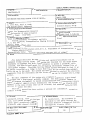
TECHNICAL REPORT STANDARD TITLE PAGE
1. Report No.
3. Recipient's Catalog No.
FHWA/TX+464-1F
4. Title and Subtitle
5. Report Dote
ESTIMATING RESIDUAL FATIGUE LIFE OF BRIDGES
1. Author/ s}
March 1988
6. Performint Organization Code
8. Performint Organization Report No.
G. Jeff Post, Karl H. Frank,
and Bahram (A lee) Tahmassebi
Research Report 464-lF
9, Performing Organization Nome and Address
10. Work Unit No.
Center for Transportation Research
The University of Texas at Austin
Austin, Texas
78712-1075
11. Contract or Grant No.
Research Study 3-5-86-464
t-;-:;;--;---:--:----:-:---~:-:-:------------------113. Type of Report and Period Covered
12. Sponaorint Agency Nome and Addreu
Texas State Department of Highways and Public
Transportation; Transportation Planning Division
P. 0. Box 5051
Austin, Texas
78763-5051
Final
14. Sponsoring Agency Code
15. Supplementary Notes
Study conducted in cooperation with the U. S, Department of Transportation, Federal
Highway Administration
Research Study Title: "Estimating Residual Fatigue Life of Bridges"
16. Abatroct
This manual describes the capabilities and operating procedures for an
automated bridge testing system. The system was developed for the Texas State
Department of Highways and Public Transportation to provide a portable, selfcontained, and user-friendly means for evaluating the residual fatigue life of
steel girder bridges. The bridge testing system has been designed so that it can
be easily installed on a bridge in less than a day and can record data automatically for up to two weeks. The system has been enclosed to protect the electronic
components from the environment and the entire system can be clamped onto a bridge
girder.
The main components of the system are a Campbell Scientific eight channel
datalogger and a Data General portable computer. The Data General computer is
used to program the Campbell to record strains measured using conventional strain
gages or special clamp-on strain transducers. The system is very flexible with
respect to the types of data that can be collected, and programs have also been
written to analyze the data.
This user's manual has been written to provide the information required to
conduct a bridge test.
17. Key Worda
automated, cesting, residual fatigue
life, steel girder bridges, data,
strain gages, transducer, Campbell
Scientific eight channel datalogger
19. Security Clauif. (of thia report)
Unclassified
Form DOT F 1700.7
20. Security Claulf. (of this pogo)
Unclassified
le·et)
No restrictions. This document is
available to the public through the
National Technical Information Service,
Springfield, Virginia 22161.
21. No. of Pagel
118
22. Priu
ESTIMATING RESIDUAL FATIGUE LIFE
OF BRIDGES
by
G. Jeff Post, Karl H. Frank and Bahram (Alec) Tahmassebi
Research Report No. 464-lF
Research Project 3-5-86-464
"Esti~ating
Residual Fatigue Life of Bridges"
Conducted for
Texas
State Department of Highways and Public Transportation
In Cooperation with the
U.S. Department of Transportation
Federal Highway Administration
by
CENTER FOR TRANSPORTATION RESEARCH
BUREAU OF ENGINEERING RESEARCH
THE UNIVERSITY OF TEXAS AT AUSTIN
March 1988
The contents of this report reflect the views of the authors, who are responsible for the
facts and the accuracy of the data presented herein. The contents do not necessarily reflect
the official views or policies of the Federal Highway Administration. This report does not
constitute a standard, specification, or regulation.
There was no invention or discovery conceived or first actually reduced to practice in the
course of or under this contract, including any art, method, process, machine, manufacture,
design or composition of matter, or any new and useful improvement thereof, or any variety
of plant which is or may be patentable under the patent laws ofthe United States of America
or any foreign country.
ii
PREFACE
Often when widening an existing highway or rehabilitating an older roadway, the
bridge superstructure does not satisfy the existing AASHTO fatigue design requirements.
The superstructure often shows no signs of distress. The decision is often made to replace
the existing bridge due to its fatigue insufficiency. A more rational procedure to judge
the remaining life of the bridge may show the existing structure can remain in service.
The resulting savings may be considerable. In addition, an accurate fatigue life assessment
method will allow the replacement of deficient bridges to be scheduled in an orderly and
efficient manner based on the estimated remaining service life.
The determination of the residual fatigue life of an in service bridge requires
an accurate means of estimating the stress history of the bridge. The procedures used
in design of new bridges do not lend themselves to accurate prediction of fatigue lives.
The design procedures do provide conservative designs by using simplified vehicle load
distribution factors, impact fractions, and design load placements. Measured live load
stresses are normally much less than the calculated design stresses. A more accurate fatigue
life prediction can be made using the live load stresses measured on the bridge during normal
traffic conditions.
The equipment and analysis procedures presented in this report are designed
to allow the fatigue life of existing bridges to be determined based on measured stress.
The equipment uses state of the art fatigue life assessment techniques. The equipment is
designed to be used without extensive training of the users, to be rugged, and reliable.
The report is written in the form of a user's manual of the equipment developed
in the study.
iii
SUMMARY
The research effort produced a portable and easy to use computer based system to
measure the fatigue stresses on a highway bridge. The equipment is light weight, protected
from the elements, and powered by ordinary rechargeable storage batteries. The equipment
is housed in weather proof aluminum boxes which mount directly to the bridge using
ordinary C-clamps. The equipment is designed to stay in place on the bridge unattended
during the data collection period. A portable lap-top type computer is used to program the
data collection hardware and to retrieve the data in the field. The process is menu driven
using software developed in the project. The system may also be used to capture the live
load stress history of a single vehicle. This was done during the field testing of the unit to
measure the stresses produced by a large special permit vehicle. The resulting stress time
history of up to eight measurement point on the bridge can be viewed within minutes after
the passage of the vehicle.
The fatigue analysis procedures use rainfl.ow counting to determine the effective
constant amplitude stress range on the bridge. The fatigue life assessment uses the stress
range-cycle relationships of the standard AASHTO fatigue detail categories. Software to
preform remaining life calculations was developed and sample calculations presented.
The equipment can use both clamp-on type strain gage transducers and single
strain gages bonded to the bridge element to measure the stresses in the bridge. Calibration procedures and calibration equipment for the clamp-on transducers were developed.
Individual bridge completion boxes are used for quarter bridge strain gages. All field wiring
is done with prefabricated silicone covered wires with mating female and male connectors
installed. Due to the modular arrangement of the wiring and the use of clamp-on transducers, the system may be installed on a typical bridge in less than four hours. The equipment
has shown excellent reliability in field tests under both rain and extreme heat. The fatigue
stress data collection of up to eight locations on the bridge is performed twenty four hours
per day for a week or more.
v
IMPLEMENTATION
The equipment developed in this project provides a simple and reliable method to
determine the fatigue damage occurring in a bridge due to service stresses. The equipment
along with the analysis techniques presented in the report provide the user with the ability
to accurately assess the estimated time to visible fatigue cracking. The use of the equipment
and analysis techniques will allow the continued use of some structures which do not satisfy
the current AASHTO fatigue design requirements. This will eliminate the unnecessary
replacement of these structures.
vii
TABLE OF CONTENTS
Page
CHAPTER ONE - INTRODUCTION . . . . . . . .
1
CHAPTER TWO - BRIDGE TESTING EQUIPMENT.
3
2.1 Equipment List . . . .
3
2.2 Equipment Description .
3
2.2.1 Campbell 21X Box
3
2.2.2 Battery Boxes . .
4
2.2.3 Data General Computer and Case.
4
2.2.4 Transducers, Strain Gage Completion Boxes, and Case.
4
2.2.5 C-Clamps and Tool Box .
11
2.2.6 Cables and Connectors. .
11
2.2. 7 Transducer Calibration Specimen .
11
CHAPTER THREE- TEST PREPARATION.
13
3.1 Test Plan. . . . . . .
13
3.2 Transducer Calibration.
16
3.3 Power Supply .
18
3.4 Desiccants . .
19
3.5 Field Equipment Check List.
19
3.6 Equipment Set-up . . . .
20
CHAPTER 4 - TEST EXECUTION
23
4.1
Program Overview . .
23
4.2 Channel Description .
25
4.3 Data Acquisition
31
. .
4.3.1 F1: Check Channels.
31
ix
4.3.2 F2: Take Single Reading.
34
.
34
4.3.3 F3: Take Zero Reading
4.3.4 F4: Zero The Data Logger .
4.3.5 F5: Capture Truck
. .
34
35
4.3.6 F6: Retrieve Truck Data .
35
4.3.7 F7: Plot Truck Data.
35
4.3.8 F8: Save Truck Data
36
4.3.9 F9: Start Rainflow Routine.
36
4.3.10 FlO: Retrieve Rainflow Data .
37
4.4 Low Level Programming Mode
38
4.5 Example Test . . . . . . . .
39
CHAPTER FIVE- ESTIMATION OF REMAINING FATIGUE LIFE
43
5.1 Background. . .
43
5.2 Program RFLO .
44
5.2.1 Using Program RFLO .
45
5.3 Calculating Fatigue Life . . . .
48
5.3.1 Fatigue Life Calculation Example .
APPENDIX.
DATA GENERAL PROGRAM LISTING
X
48
57
LIST OF FIGURES
Page
2.1
Campbell 21X Box.
.
5
2.2
Campbell Box Connector Numbers.
6
2.3
Right Side of Campbell Box.
7
2.4
Campbell Box Wiring Diagram
8
2.5
Battery Box.
2.6
Data General Computer
2. 7
Transducers, Completion Boxes, and Case
10
10
2.8
Transducer calibration specimen.
12
3.1
Bridge Test Data Sheet.
14
3.2
Transducer Calibration Program.
17
3.3
Equipment Set-up .
21
4.1
Main Menu .
4.2
Example Test Data Sheet.
26
4.3
Channel Description Input Screen
27
4.4
Example Channel Description Data
32
4.5
Data Acquisition Menu.
33
4.6
Example Test . .
40
5.1
RFLO Input Screen
45
5.2
Printout from RFLO Program.
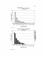
5.3
Stress Range Histogram- All Intervals .
5.4
Stress Range Histogram- Each Interval.
5.5
Cycles Per Interval.
47
49
49
50
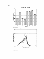
5.6
Fatigue Damage Factor.
50
5.7
Spreadsheet Output .
51
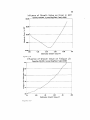
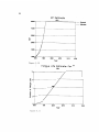
5.8
Influence of Growth Value on Error in ADT.
53
5.9
5.10
Influence of Growth Value on Fatigue Life
ADT Estimate
.
53
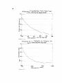
5.11
Fatigue Life Estimate- Years .
54
54
5.12
Influence of Cycles/Day From Field Test .
56
5.13
Influence of ADT Capacity on Fatigue Life
56
Bl
Changing Scan Rate .
65
.
. .
9
.
24
I
xi
CHAPTER ONE
INTRODUCTION
This manual describes the capabilities and operating procedures for an automated
bridge testing system. The system was developed for the Texas State Department of Highways and Public Transportation to provide a portable, self-contained, and user-friendly
means for evaluating the residual fatigue life of steel girder bridges. The bridge testing
system has been designed so that it can be easily installed on a bridge in less than a day
and can record data automatically for up to two weeks. The system has been enclosed
to protect the electronic components from the environment and the entire system can be
clamped onto a bridge girder.
The main components of the system are a Campbell Scientific eight channel datalogger and a Data General portable computer. The Data General computer is used to
program the Campbell to record strains measured using conventional strain gages or special clamp-on strain transducers. The system is very flexible with respect to the types of
data that can be collected. The Campbell can be programmed to record data continuously
while a truck of known weight crosses a bridge and this data can be used to check analysis
results. The Campbell can also be programmed to record and count stress cycles using the
rainflow method for use in fatigue analysis. Other types of special tests can also be set up.
Programs have also been written to analyze the data.
This user's manual has been written to provide the information required to conduct a bridge test. Chapter 2 describes the equipment that makes up the bridge testing
system and Chapter 3 contains the procedures needed to prepare for a bridge test and to
set up the equipment. Chapter 4 describes the use of the programs written for conducting
a test and Chapter 5 discusses the program written for analyzing the test results. The appendices contain program listings and additional detailed information. Further information
on the operation of the system can be found in the Campbell Scientific and Data General
manuals.
1
CHAPTER TWO
BRIDGE TESTING EQUIPMENT
2.1 Equipment List
The following major equipment comprises the bridge testing system.
- Campbell Scientific 21X Micrologger
- aluminum box for micrologger
- two Stowaway 12 volt batteries
- two aluminum battery boxes
- Data General (DG) One computer
- computer carrying case
- five strain transducers
- five strain gage completion boxes
- c~rrying case for transducers and completion boxes
- 12 - 50 foot cables
- 4 - 90 foot cables
- 30 three inch C-clamps
- tool box for C-clamps
- transducer calibration specimen
2.2 Equipment Description
This section contains a general description of the major pieces of equipment.
More detailed specifications for the equipment can be found in Appendix C.
2.2.1 Campbell 21X Box. The Campbell 21X Micrologger is mounted in an
aluminum box which provides protection for the 21X during deployment. The box also
provides connectors which greatly simplify the field hook-up of transducers, strain gages,
and batteries to the Campbell. The box is constructed of 3/16-in. thickness aluminum and
3
4
has outside dimensions of 25 x 10 x 11-in. and is shown in Figure 2.1. The top of the box
is bolted on and is oversized to provide for ventilation.
The left side of the box has eight connectors corresponding to the eight input
channels of the Campbell. Figure 2.2 shows the channel number corresponding to each
connector. The right side of the box is equipped with two battery connectors and a connector for the Data General computer. The arrangement of these connectors is shown in
Figure 2.3. A voltmeter is also provided to indicate the voltage level of the battery(s) connected to the Campbell. The small button to the left of the voltmeter is used to activate
the meter. The small light below the voltmeter indicates whether or not the Campbell is
currently taking data. If the light flashes when the button next to it is pushed, then the
Campbell is taking data.
Also included in the Campbell box is a small black communication box which
is required to establish communication between the Campbell and the DG computer. A
schematic of the wiring arrangement in the Campbell box is shown in Figure 2.4. The
specifications and complete operating instructions for the Campbell can be found in the
Campbell operator's manual.
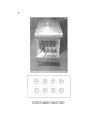
2.2.2 Battery Boxes. The two battery boxes are made of aluminum and have
construction similar to the Campbell box. The outside dimensions of the box are 20 x 14
x 11-in. and the box is shown in Figure 2.5. The batteries used are Stowaway 12 volt
sealed marine batteries rated at 154 amp-hours. A plastic battery box is mounted in the
aluminum box to hold the battery in place and to contain any spilled battery acid in the
event of a leak. The batteries must be slow charged and can be fully charged in about
12 hours using a 15 amp charger. A 1 amp fuse has been wired into the battery cable to
protect the Campbell.
2.2.3 Data General Computer and Case. A lightweight carrying case made
by the Zero Corporation has been provided for the Data General/One, Model Two portable
computer. The Zero carrying case is filled with foam that has been cut to hold the DG
firmly in place during transportation. The computer has 256 kilobytes of memory and uses
the MS-DOS operating system. The computer can run off of an internal battery or from an
external 7.5 volt power supply. The computer and carrying case are shown in Figure 2.6.
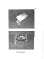
2.2.4 Transducers, Strain Gage Completion Boxes, and Case. Five clamp
on strain transducers and five strain gage completion boxes have been provided. Figure
2. 7 shows the Zero carrying case which has been provided for storing the transducers and
FIGURE 2.1 Campbell 21X Box
8888
8888
FIGURE 2.2 Campbell Box Connector Nwnbers
7
voltm~ter
DG
f?::\
\:Y
0
0
D
0
batt e ry
FIGURE 2.3 Right Side of Campbell Box
0
I i ght
00
Campbell Input Channels
(f)
,_
Q)
.0
E
:::l
z
Q)
r:::
r:::
co
..r:::
0
5)
4 J
.I
3
'U+-t
I
I
I
Excitation Channels
2 )
Battery Inputs
1
'!
FIGURE 2.4 Campbell Box Wiring Diagram
+12
g
FIGURE 2.5 Battery Be.
10
FIGURE 2.6 Data General Computer
FIGURE 2.7 'fransducers, Completion Boxes, and Case
11
completion boxes. The transducers were manufactured by Bridge Weighing Systems, Inc.
The transducers include four 350 ohm strain gages wired in a full bridge configuration
and provide a mechanical amplification of approximately 7.5. The strain gage completion
boxes contain three 120 ohm resistors for use with 120 ohm strain gages. The resistors are
manufactured by Micro-Measurements and are guaranteed to have a resistance within .01%
of 120 ohms. The completion boxes have been sealed to protect the circuit from moisture
and should not be opened unless repairs are necessary.
2.2.5 C-Clamps and Tool Box. C-clamps are used to fasten the Campbell and
battery boxes to the bridge girder. They are also used to clamp down the transducers and
compl€tion boxes. Thirty 3 inch clamps have been provided for this purpose. A tool box
has also been provided for storing and carrying the clamps. Space is also available in the
tool box for additional tools as required.
2.2.6 Cables and Connectors. Approximately 1000 feet of cable in various
lengths has been provided to connect the instrumentation to the Campbell. The cable is
manufactured by Belden and is insulated with teflon and has a silicon jacket. All of the
cable is 4 wire except for the strain gage completion boxes which use 3 wire cable to connect
to the strain gages. The connectors are standard Amphenol connectors. The transducers,
strain gages, and DC computer use 5 pin connectors and the 12 volt batteries use 2 pin
connectors. All of the connectors are sealed to prevent shorting due to moisture.
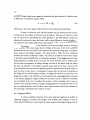
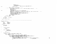
2.2.7 Transducer Calibration Specimen. The calibration specimen has been
fabricated to fit in a standard tensile testing machine and can be used to calibrate the strain
transducers. The specimen is shown in Figure 2.8 and is made of .375-inch thick A514 steel
( 100 ksi yield strength). The total length is 37 inches and holes have been drilled on the
neck of the specimen for bolting on the transducers. The width of the neck is 2 inches and
the cross sectional area is . 75 in. 2 • Strain gages have been mounted on both sides of the
specimen and these can be used to measure the applied stress if desired. The strain gages
have a resistance of 120 ohms (±.15%) and have a gage factor of 2.04. The procedures
required for using the specimen to calibrate the transducers are given in Section 3.2.
12
r
1/4"dia. (typ.)
0
4·0'-+---1~~~=~
=a:==~
---~~>~•1 ~
11'4--:- - 1 0..-
4"
·1
4
7·
·~
4"
·I ~~-10-____.:1
37"
Fig. 2.8
I
Transducer Calibration Specimen
..
CHAPTER THREE
TEST PREPARATION
Prior to conducting a bridge fatigue test proper preparation is required to help
insure that quality data is obtained. The major tasks involved in test preparation are the
development of a test plan, calibration of the strain transducers, assembling and setting up
the required equipment, and arranging for access to the bridge.
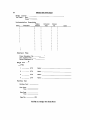
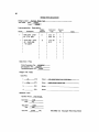
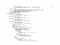
3.1 Test Plan
The initial step required in preparing for a bridge test is to clearly define a test
plan. The test plan should identify the locations to be instrumented, the fatigue category
of each location, the type and number of instruments (strain gages or transducers) at each
location, the length of the test, and whether continuous or rainflow data is to be taken. A
test plan must be developed which is within the limitations of the data acquisition system
and which gives a clear picture of the fatigue condition of the bridge. Figure 3.1 is a data
sheet which can be used in putting together a test plan.
The data acquisition system has been developed to be as flexible as possible, but
the following limitations must be considered when developing the test plan.
- Number of Data Channels
The maximum number of channels of data that can be taken at one
time is eight. Any combination of strain gages and transducers can be
used.
- Maximum Test Length
The maximum test length depends on whether continuous or rainflow
data is taken and is controlled by the memory capacity of the equipment.
When taking rainflow data, the maximum test length depends on the
rainflow period being used. The rainflow period is selected by the user
and is discussed in Section 4.4. The rainflow period can range from one
minute to one day. When rainflow data is taken on all eight channels,
the maximum number of rainflow periods for which data can be taken
is 18. For example, if a rainflow period of 24 hours is specified, then
18 days of data can be taken and stored. If the Campbell is allowed to
13
14
BBIQGE TEST PAIA SHEET
Bridge Location :
Test Dates- Start: _ _ __
Finish:
Instrumentation
Loc.#
Description
Fatigue
Category
Descrjptjon
Description
Instrument
Type
Channel
No.
Notes
Files
Channel Description File : _ _ _ _ __
Zero Description File : _ _ _ _ __
Rainflow Description File : _ _ _ __
Single Truck Tests
Data Files:
1. _ _ _ _ .STK
Notes: - - - - - - - - - - - - - - - - - -
2. _ _ _ _ .STK
Notes: - - - - - - - - - - - - - - - -
3. _ _ _ _ .STK
Notes: - - - - - - - - - - - - - - - -
4. _ _ _ _ .STK
Notes: - - - - - - - - - - - - - - - -
Rainflow Test
Rainflow Period : _ _ _ __
Start Date : _ _ _ _ __
Time : _ _ _ _ __
Stop Date : _ _ _ _ _ __
Time : _ _ _ _ __
Data File : - - - - .RFL
FIGURE 3.1 Bridge Test Data Sheet
15
take data for 19 days, then the first day of data will be overwritten and
only the data for the last 18 days will be recoverable.
If a greater number of rainflow periods are desired, then the number of
channels of data being taken must be reduced. The maximum number
of rainflow periods can be calculated for a given number of data channels
using the following formula:
. fl
. d
num ber 0 f ram OW periO S =
14 556
(number of channels)(l00)+3
If the total length of time for which data is going to be taken exceeds
18 days, then the battery life needs to be considered (See section 3.3).
When taking continuous data (single truck test) the maximum length of
the test depends on the rate at which data is being taken. A maximum
of 660 scans can be taken for any given single truck test. One scan
consists of one reading of each active channel. The maximum test length
is then equal to the scan rate times 660. The scan rate is automatically
se~ to .0125 seconds by the Data General. This is the fastest possible
scan rate that the Campbell can use. With the .0125 second scan rate,
the maximum length of a single truck test would be approximately 8.25
seconds. If several channels are being used, the Campbell may not
be able to actually scan each of the channels every .0125 seconds and
the maximum test time may actually be longer. If longer test lengths
are desired then the scan rate must be increased. If a test length of
90 seconds is desired then the scan rate must be set to .136 seconds
or greater. The procedure for adjusting the scan rate is discussed in
Appendix B.
- Instrumentation Spacing
All of the locations that are to be instrumented must be connected
by cable to the Campbell box. The maximum spacing between the
instrumentation is therefore limited by the length of available cable.
Four 90-foot cables and twelve 50-foot cables have been provided. These
cables can be connected together to make longer lengths, if necessary.
The cable lengths should be kept as short as possible to minimize noise
and signal attenuation.
16
- Type of Instrumentation
Five clamp-on strain transducers have been provided with the system.
If more channels of data are desired, then 120 ohm strain gages must be
used or more strain transducers acquired. If strain gages are used they
must be used with the strain gage completion boxes. Five completion
boxes are provided.
Once the test plan has been developed, the channel description data as described
in Section 4.3 can be entered and saved on the Data General computer. This will help
reduce the time required to set up the test in the field.
3.2 Transducer Calibration
Each of the strain transducers provides a slightly different amplification of the
actual strain values and therefore each transducer must be calibrated individually. The
calibration data that must be input into the test program for each transducer is the output
of the transducer in millivolts/volt for a specified stress level. The calibration is performed
by bolting a transducer to the calibration bar and applying a known load. The calibration
bar is shown in Fig. ' 2.8. The stress in the bar can be calculated using the bar cross
sectional area of .75 in. 2 and the output of the transducer can be read using the Campbell.
The output of the transducer represents its calibration for the applied stress level. The
following procedure should be used to obtain the transducer calibration data.
The calibration bar should be mounted in a test machine which is tall enough to
handle the 37" long bar with a tension capacity of at least 10 kips. The load indicator on
the test machine should be zeroed after clamping down the calibration bar. One transducer
can then be bolted to the specimen and connected to channel 1 of the Campbell box. A
12V battery should also be connected to the box to provide power for the Campbell. The
Campbell must then be programmed to read data from the transducer. For the calibration
test it is best to program the Campbell directly using the Campbell keyboard, as opposed
to using the DG for programming. The keystrokes required for the program are shown in
Figure 3.2. After the battery is connected to the Campbell, the Campbell will come on,
check the memory circuits, and then display "11:1111.11" on the screen. After the eight
ones are displayed, programming can begin. Each entry in the program should be followed
by an "A"' to advance to the next program step. If a mistake is made in a program entry, the
"B" key can be used to backup and the previous entry can be corrected. Alternatively, the
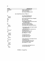
17
KEY
FUNCTION
*1 A
D5A
6A
enter programming Table 1
execution interval 0.5 seconds
Instruction #6: full bridge measurements
1 strain transducer being read
±50 millivolt range
input channel number for transducer
use excitation channel 1
4000 m V excitation
use storage location 1
use multiplier of 1
use offset of 0
exit programming table, begin taking data
display transducer reading in m V/V
1A
13 A
1A
1A
4CXX)A
1A
1A
OA
*O
* 6A
FIGURE 3.2 'fransducer Calibration Program
18
power can be disconnected from the Campbell and then reconnected and the programming
started again from the beginning. Additional information on programming the Campbell
can be found in the Campbell User's Manual.
After the Campbell has been programmed, the calibration test can begin. The
transducer reading at zero load should be recorded and then load should he applied in 1
kip increments up to approximately 6 kips {8 ksi). The Campbell will continuously display
the output of the transducer in MV /V. Transducer and load readings should be taken
at each increment. The same procedure should then be followed for unloading. The test
loading should not exceed six kips because the configuration of the transducers causes stress
concentrations which can lead to local yielding of the transducers at higher load levels.
After the load has been removed the transducer should be moved to the other side
of the calibration bar and the test repeated. The results of the two tests should be averaged
in order to remove the effects of any bending that might be occurring in the specimen.
The required transducer calibration data can then be determined by plotting the
transducer output in MV /V versus the stress in the calibration bar. The transducer output
will be equal to the transducer reading minus the original transducer reading at zero load.
The stress in the calibration bar will be equal to the load reading divided by the cross
sectional area of . 75 in. 2 • A best fit line should be determined for the data and any point
on the line can be taken as the calibration data for the transducer. It is recommended that
the calibration test be run two or three times for each transducer and the results averaged.
The transducers should be recalibrated after every three or four tests or whenever
a transducers has been subjected to stresses over approximately 10 ksi.
3.3 Power Supply
Power for running the Campbell during a test is provided by 12-volt marine
batteries. If fully charged, one battery provides enough power to operate the Campbell for
at least 18 days when all eight channels are being used. If fewer channels are being used,
then the Campbell can operate longer. If a longer test is desired then a second battery can
be connected to the Campbell and the operating duration will be doubled. Two battery
connectors, wired in parallel, have been provided on the Campbell box for this purpose.
Batteries can also be switched out during a test. A fully charged battery can be connected
to the second battery connector and the old battery can then be disconnected. Two 12V
batteries have been provided with the system.
19
The operating times given above are based on the performance of relatively new
batteries operating at moderate temperature ( approx. 70° F). Consideration should be
given to the drop in performance of the batteries with age and at lower temperature.
Battery performance will drop considerably if the test is conducted at colder temperatures.
Extreme care should be taken to insure that sufficient battery power is available for the
full length of the test since all of the data will be lost if the battery voltage drops below
the threshold needed to operate the Campbell.
A power supply is also required for the Data General during test set-up and data
retrieval. The Data General has an internal battery which when fully charged can operate
the computer for a maximum of two hours. Additional power can be provided by a portable
generator or by the 12V batteries. A special adaptor has been provided which converts the
12V battery supply to the 7.5V used by the DG. The cable on this adapter is approximately
15 ft long and has a 2-pin connector for connecting to the battery. It should be noted that
running the Data General off of the 12V batteries will reduce the length of time which
the Campbell can run. Care should also be taken when running the Data General off of a
portable generator since sudden power surges can damage the computer. An in-line voltage
meter is useful in monitoring the output of the generator.
~
3.4 Desiccants
Inside the Campbell are several small desiccant packages. These packages contain
material which absorbs moisture from the air to prevent possible damage to the Campbell
circuits. At least once a year these packages need to be taken out of the Campbell and dried.
To remove the desiccants the top of the Campbell must be removed. Special care should
be taken not to disturb the wiring connected to the Campbell. The desiccant packages can
then be placed in an oven to dry. The packages should be dried for 6 hours at 250° F and
then replaced in the Campbell.
3.5 Field Equipment Check List
The following equipment is required in the field to set-up and run a bridge test:
- Campbell 21X box
- 12V battery and box
- Data General computer
- strain transducers
20
- cables: computer to Campbell and transducers to Campbell
- C-clamps
- tool box
In addition, the following equipment may be required depending on the type of
test planned:
- strain gages
- strain gage installation supplies
- strain gage completion boxes
- converter for running Data General off of 12V battery
- voltmeter
- camera
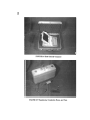
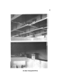
3.6 Equipment Set-up
Once the equipment has been transported to the test site, the actual set-up can
be done fairly quickly. Figure 3.3 shows a typical set-up of the equipment. The order in
which the equipment is mounted on the bridge is arbitrary and can be determined based on
the method of access being used to get to the various locations on the bridge. The battery
box must be mounted near the right side of the Campbell box and connected into one of
the two pin connectors. The Data General also connects into the right side of the Campbell
box. Figure 2.3 shows the location of these connectors on the box. Once the Data General
and the battery have been connected, programming of the Campbell can begin regardless
of whether the transducers have been connected.
The cables from the transducers and strain gages connect into the left side of the
Campbell box. The eight connectors correspond to the eight input channels as shown in
Figure 2.2. The cables should be wrapped around a C-clamp or a secondary bridge member
near the Campbell box so that the cable weight will not be pulling on the connector. The
same should be done for the connectors at the transducers and strain gages. The cables
should be pulled tight to prevent them from hanging below the girder.
When installing the transducers, the C-clamps should be tightened by hand as
tightly as possible to insure that no slipping occurs. When strain gages are used the strain
21
FIGURE 3.3 Equipment Set..up
22
gage completion boxes should be clamped to the girder and the connection to the gage
should be insulated from moisture.
After all of the equipment has been connected, two checks can be made to see if
the Campbell is working properly. On the right side of the campbell box is a voltage meter
which can be used to check that power is getting to the Campbell. The button next to the
meter must be pushed to activate it. Figure 2.3 shows the location of the meter. Below
the meter is a light which flashes when the Campbell is taking data. The light must be
activated by pushing the button next to it. The light will only come on after the Campbell
has been programmed. The light will flash each time the Campbell takes data.
CHAPTER4
TEST EXECUTION
Once the equipment has been set-up properly, a test can be controlled and executed directly from the Data General(DG) computer. The Campbell can be programmed
using the DG and direct physical access to the Campbell is not required. The DG is connected to the Campbell by a cable which plugs into the serial port on the back of the
DG.
The DG is an IBM compatible machine which uses the DOS operating system.
It includes a 10-megabyte hard disk for permanent storage and a 3-1/2" floppy disk drive
that can be used for transferring data to and from other IBM compatible machines. The
programs supplied on the DG have been written specifically for the purpose of conducting
bridge tests. The programs provide for a quick and simple means of programming the
Campbell, recovering data from the Campbell, and performing preliminary analysis of the
data. The specifics of using the programs for conducting a test are discussed in the following
sections.
4.1 Program Overview
The primary program used to conduct bridge tests is titled 21X. This program
was written by Alec Tahmassebi and a listing of the program code is included in Appendix
D. The 21X program and others used for conducting bridge tests are stored on the DG hard
disk in the CAMPBELL sub-directory. The program can be executed simply by typing 21X
while in the CAMPBELL directory. The 21X program is menu driven and upon entering
the program the main menu is displayed. The main menu is shown in Figure 4.1. From this
menu three options can be selected using the function keys at the top of the DG keyboard
or the program can be exited by pressing ESC. Pressing the F3 key enters the low level
programming mode for the Campbell. This can be used to check the current program in
the Campbell, to change the scanning rate, to modify the Campbell program, or to input
a completely new program. It will not be necessary to use this mode for most tests. The
F5 key brings up the channel description screen which is used to input the number and
configuration of strain gages and transducers. Inputting the channel description data will
normally be the first step in conducting a test. The F9 key accesses the data acquisition
menu which is used to take and retrieve data. Each of these three secondary menus will
be discussed further in the following sections. To return to the main menu from any of the
23
...
t.)
TEXAS STATE DEPARTMENT OF HIGHWAYS AND PUBLIC TRANSPORTATION
F3 : Low Level Programming
F5 : Channel Description
F9 : Data Acquisition Menu
ESC : Exit to DOS
Fig. 4.1 Main Menu
25
secondary menus use the ESC key. It is not possible to move directly from one secondary
menu to another secondary menu.
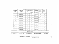
To illustrate the use of the program, an example test will be discussed. The
appropriate steps for conducting the example test will be given with the discussion of
each of the program functions. The example test will involve taking both single truck
(continuous) and rainflow type data at two locations on a bridge. The first location is a
category C weld detail and will be instrumented with two strain transducers. The second
location is a category E' weld detail and will be instrumented with one strain transducer and
one strain gage. The test data sheet is shown in Figure 4.2. Assuming that the equipment
is set-up properly as discussed in Section 3.6, the steps necessary to execute the example
test will be discussed in the following sections and will be listed in Section 4.5.
4.2 Channel Description
The first step in executing a test is to input the channel description data. This
is done using the channel description screen shown in Figure 4.3. The channel description
data is used to tell the Campbell which of the eight input channels will be active and what
type of instrumentation will be connected to each channel. The channel description screen
is accessed from the main menu using the F5 key. The arrow keys at the bottom right
corner of the keyboard can be used to move around the screen. The following input is
required for each channel to be used.
1. Channel No.: The channel number corresponds to the input channel being used
on the Campbell. The connectors for each Campbell channel are numbered on
the outside of the Campbell box. If the cable from a strain gage or transducer
is connected to the number 2 connector on the Campbell box, then the data for
that gage or transducer should be entered into the channel number 2line on the
screen.
2. Channel Type: In this space a G should be entered if a strain gage is being used
on this channel and a T should be entered if a transducer is being used. This
information is used to set the expected input voltage range for the channel.
3. Calibration: This column is used to input the specific calibration data for the
strain gage or transducer being used on this channel. Two related inputs are
required. A stress level in ksi is entered in the S column. The stress level can
be chosen up to a value of 99.99. A MV /V value is then entered in the adjacent
26
BRIDGE TEST PATA SHEET
Bridge Location : Example Bridae Test
Test Dates - Start:
1120/88
Finish:
1128/88
Instrumentation
Loc.#
Description
Fatigue
Category
Description
I
I field splice , girder
I #4, 2nd span
2
I
I cover plate , girder
I #4 , north side ,
I 1 st support
I
I
l
I
I
I
I
I
Description
I
I
I
I
I
I
I
I
I
I
I
I
I
I
I
C
E'
Instrument
Type
trans
trans
#1
#3
trans #4
S.G.
Channel
No.
Notes
1
2
4
5
Files
Channel Description File : EXAMPLE
Zero Description File : -.~E..:X~Z...,Eo!.R~o~---Bainflow Description File : _E
...'X~Ru.F,~.,~L....__ __
Single Truck Tests
Data Files:
1. _ _
EXc.A~_ _.STK
Notes:
tuf(y fqaded gravel truck in rjght lane
2. --'E""XI.IOB'----··STK
Notes:
mQbUe home ja center lane
3. _ _ _ _ .STK
Notes: - - - - - - - - - - - - - - - - -
4. _ _ _ _ .STK
Notes: - - - - - - - - - - - - - - - - -
Bainflow Test
Bainflow Period :
1440 minutes
Start Date:
Time:
1/20188
14:20
Stop Date:
Time:
1128188
9:55
Data File:
E:,XRFl.
.BFL
FIGURE 4.2 Example Test Data Sheet
s
MV/V
Fatigue
Detail#
Undefined
?
?
Undefined
?
?
2
Undefined
?
?
Undefined
?
?
3
Undefined
?
?
Undefined
?
?
4
Undefined
?
?
Undefined
?
?
5
Undefined
?
?
Undefined
?
?
6
Undefined
?
?
Undefined
?
?
7
Undefined
?
?
Undefined
?
?
8
Undefined
?
?
Undefined
?
?
Channel
no.
Channel
Type
i
Calibration
Sr
max
Sr
min
~~~
I
I
--
Message Line
Fi: Load File
F2: Save File
FIGURE 4.3
F3: Send File
Del: Erase Channel
Channel Description Input Screen
ESC: Exit
w
~
28
column which corresponds to the stress level entered in the first column. A linear
relationship between the stress level and the strain gage output is assumed and
the MV /V value represents the voltage output of the gage (in millivolts) divided
by the excitation voltage for the selected stress level. For a strain gage, the
Campbell is programed to use an excitation voltage of 4 volts and the MV /V
value can be calculated using the following formula:
MV/V
:.=
S * G.F. / (.004 *E)
where:
S
:.=
calibration stress level in ksi
G.F. =gage factor for strain gage
E =modulus of elasticity in ksi
The value should be entered with two significant figures to the right of the decimal
point. If the value is less than one then the entry must include a zero before the
decimal poi~t (ex. 0.50). For a transducer, the MV /V value should be determined
from a calibration test as described in Section 3.2.
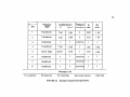
4. Fatigue Detail No.: The AASHTO fatigue category for the detail to be instrumented should be determined in order to establish the maximum stress range that
can be expected. The AASHTO categories are designated alphabetically from A
toE'. The alphabetical category should be entered using the fatigue detail numbers shown on the message line at the bottom of the channel description screen.
Category A is represented by 1, category B by 2, and so forth until category E'
which is represented by 7. When a fatigue detail number between 1 and 7 is entered, default values for maximum and minimum stress ranges are automatically
entered into the next two columns. The default maximum stress range value is
the expected maximum stress for the specified type of detail and the minimum
stress range is set at a level sufficient to prevent recording electronic noise. The
default values may be modified if desired. When one channel is modified, the
other channels with the same fatigue detail number are automatically updated
with this modified value. F5 will restore the Sr Max and Sr Min values to the
original default values. The default values are shown below.
29
CATEGORY
A
DETAIL NO.
1
SrMAX
28 ksi
Sr MIN
3 ksi
B
B'
2
20
2
3
16
1
c
4
16
1
D
5
14
1
E
E'
6
9
.5
7
5
.5
For continuous data collection it is not necessary to enter a fatigue detail number
based on the AASHTO categories. Any number from 1-99 may be entered. For
numbers from 8-99, no values for maximum and minimum stress ranges will appear and these stress range limits should be entered as described in steps 5 and
6.
5. Sr Max: The maximum stress range that is expected during the test on this
channel should be input in ksi. The default values based on the fatigue detail
number may be changed if desired. In the rainflow mode, stress cycles with
ranges up to the maximum stress range plus 5% will be recorded properly. Stress
cycles exceeding this value will be recorded, but will be assigned the value of the
maximum plus 5%. For continuous data tests, the Sr Max value is used for scaling
only and does not actually limit the maximum stress that can be recorded.
The absolute maximum stress values that can be recorded are governed by the
maximum voltage range that the Campbell is set to and the calibration of the
strain gage or transducer. The Campbell voltage range that is set automatically
by the 21X program is ±5 m V for strain gages and ±50 m V for transducers. This
allows a stress of greater than 50 ksi to be recorded when using transducers or
strain gages with gage factors of approximately 2. The Campbell voltage range
may be increased using the low level programming mode if higher voltage ranges
are required.
6. Sr Min: In the rainflow mode it is necessary to enter a minimum stress cycle value
that is to be recorded. This is to prevent the recording of low level cycles that are
the result of electronic noise or are of no structural significance. A value of 0.5
ksi is generally sufficiently low to prevent recording of noise cycles. The default
30
values that are entered based on the fatigue detail number used are based on the
best judgement of the authors as stress ranges which would produce insignificant
fatigue damage. For continuous data tests, the Sr Min value has no effect on the
test and any value may be entered.
The above information can be input in any order and as the cursor is moved from
column to column a message is displayed near the bottom of the screen which gives helpful
information about the data to be input in that particular column.
Below the message line is displayed the function keys which can be used from
the channel description screen. The Fl and F2 keys can be used to load and save channel
description files. These functions are useful because they allow the channel input data
to be input prior to going into the field. The Fl key can be used to load a previously
saved file into the channel description screen. When the Fl key is pressed, a prompt will
be given requesting the filename of the file to be loaded. When the F2 key is pressed to
save the channel data, a prompt will be given requesting a filename for the data to be
saved. The filename should be in the standard DOS format. It is not necessary to enter
a filename extension since the DG will automatically assign an extension of "21X" to the
file. The same channel description file can then be retrieved by pressing Fl and entering
the filename. It is not necessary to type the "21X" extension. If a mistake is made when
entering a filename, the backspace key in the upper right corner of the keyboard can be
used to go back and correct the entry.
The F3 key is used to send the channel description data to the Campbell datalogger. The DG is effectively programming the Campbell to take data on the specified
channels. This programming takes 1 or 2 minutes and a message is flashed on the DG
screen indicating that the Campbell is being programmed. It is recommended that the
channel description data be saved using the F2 key prior to sending the program using the
F3 key. The channel data remains in the 21X program until the program is exited, but it
should be saved in case it is necessary to come back to it at a later time or if the program
is abnormally exited due to a power failure. When the program is sent, the Campbell is
turned on and begins to take data. However, the Campbell does not store the data taken
until it is given instructions to do so using one of the commands on the data acquisition
menu.
The other keys shown at the bottom of the screen are the DEL and ESC keys.
The DEL key erases all of the information that has been entered for the channel that the
pointer is currently on. The ESC key is used to return to the main menu.
31
The channel description screen for the example problem discussed earlier is shown
in Figure 4.4. The two transducers to be used at the category C weld detail are connected
into channels 1 and 2. The calibration for the transducers is 0.81 MV /V output at 7.0 ksi
for the first transducer and 0.94 MV /Vat 7.0 ksi for the second transducer. A category C
detail corresponds to a fatigue detail number of 4 and the default values of 16.00 ksi and
1.00 ksi for the maximum and minimum stress ranges will be used. For the category E'
detail, one transducer and one strain gage will be used and they are connected to channels
4 and 5. The calibration for the transducer is 0.95 MV /V at 7.0 ksi and the calibration for
the strain gage is 0.35 MV /V at 20.0 ksi. Category E' corresponds to fatigue detail number
7 and again the default values for Sr Max and Sr Min will be used. Once the data has
been entered as shown in the figure, the data should be saved using the F2 key and then
sent to the Campbell using the F3 key. The channel description data was saved under the
filename EXAMPLE.21X. After the data has been sent, the Campbell is programmed and
is ready to take data. The ESC key can then be used to return to the main menu.
4.3 Data Acquisition
The data acquisition menu is accessed from the main menu using the F9 key and is
shown in Figure 4.5. The main functions that are controlled from this menu include checking
the data being received from the individual channels, zeroing the channels, initiating the
collection of single truck (continuous mode) and rainfiow data, and retrieving single truck
or rainfiow data from the Campbell. To use the functions on this menu the Campbell
must have already been programmed previously, i.e. the channel description sent to the
Campbell. The specific tasks carried out by each of the function keys are discussed below.
4.3.1 Fl: Check Channels. This function and F2 are used to check that each
of the active input channels are giving reasonable readings. When the F1 key is pushed,
the Campbell is instructed to take data for a few seconds. After the data has been taken
the DG then automatically retrieves the data from the Campbell and processes it. The
scan number shown at the bottom of the screen indicates the number of readings for each
channel that are still to be processed. After processing has been completed, the high,
low, and average readings (in MV /V) are displayed for each of the channels which were
specified on the channel description screen. If the Campbell has not been previously zeroed
(see F3 and F4), then the data displayed will be raw data read directly from the strain
gages or transducers. If the Campbell has previously been zeroed then the data displayed
(Ill
w
s
MV/V
Fatigue
Detail#
Transducer
7.00
0.81
4
16.00
1.00
2
Transducer
7.00
0.94
4
16.00
1.00
3
Undefined
?
?
Undefined
?
?
4
Transducer
7.00
0.95
7
5.00
0.50
5
Strain Gage
20.00
0.35
7
5.00
0.50
6
Undefined
?
?
Undefined
?
?
7
Undefined
?
?
Undefined
?
?
8
Undefined
?
?
Undefined
?
?
Channel
no.
Channel
Type
1
Calibration
Sr
max
Sr
m1n
Message Line
F1: Load File
F2: Save File
FIGURE 4A
F3: Send File
Del: Erase Channel
Example Channel Description Data
ESC: Exit
33
TEXAS STATE DEPARTMENT OF HIGHWAYS AND PUBLIC TRANSPORTATION
F1
=
Check Channels
F2
=
Take Single Reading
F3
-
Take Zero Reading
F4
=
Zero the Data Logger
FS
F6
=
=
F7
..
F8
=
Capture Truck
Retrieve Truck Data
Plot Truck Data
Save Truck Data
F9 =
F10 "'
Start Rainflow Routine
Retrieve Rainflow Data
ESC ...
Exit to main menu
Waiting for command ...
Fig. 4.5 Data Acquisition Menu
34
will include the offsets used in the zeroing process. If the data are far from zero (> ±1.0
MV /V) then a good zero has not been obtained and the Campbell should be rezeroed.
4.3.2 F2: Take Single Reading. This function is similar to the Check Channels
function. It instructs the Campbell to take data and then retrieve and display it. However,
unlike the Check Channels function, it only retrieves one data point instead of retrieving
several points and averaging them. The advantage of this function is that it is much
quicker than the Check Channels. It only takes a few seconds to execute. The single
reading function also differs from the check channels function in that even if the channels
have been zeroed, the F2 function will always give the raw data read directly from the
strain gages or transducers.
4.3.3 F3: Take Zero Reading. When the strain gages and transducers are
installed, they will not produce a zero electronic output. It is necessary to subtract these
initial non-zero outputs from each channel so that all of the channels will read zero stress
under the same conditions and also to allow the full dynamic range of the Campbell to be
utilized. This is referred to as zeroing and must be done before running a test. Zeroing is
accomplished using the F3 and F4 functions. The F3 function instructs the Campbell to
take data for a few seconds and the DG then retrieves the data for each active channel.
The data are then averaged and displayed for each channel. These average values are saved
by the DG and are used to zero the Campbell when the F4 function is used. The F3 key
should be pressed when there is relatively little traffic on the bridge. Some automobile
traffic is acceptable, but no truck traffic should be on the bridge when the zero readings are
taken. H a truck should enter the bridge while zero readings are being taken, the zeroing
function should be repeated by pressing the F3 key after the current zeroing operation is
complete.
4.3.4 F4: Zero The Data Logger. After satisfactory zero readings have been
taken using the F3 key, the Campbell must be reprogrammed using the zero values. The
F4 function is used to accomplish this. Pressing the F4 key instructs the DG to reprogram
the Campbell using a multiplier and offset which are derived from the zero values for each
channel. The multiplier and offset values act on the raw data to give the zeroed values
desired. Before reprogramming, the DG will ask for a filename to use for saving the description file. This description file will contain the data entered into the channel description
screen, the zero readings, and the multiplier and offset values used. This information must
be saved since it is used to retrieve and process the data. The filename should be different
than the filename used to save the channel description data. The channel description data
35
file contains default multiplier and offset values of 1 and 0. This channel description data
file may be used again for another test at a later time, but the description file containing
the actual zero, multiplier, and offset values should not be reused. No filename extension
should be given, the DG will assign an extension of "21X". This is the same extension
that is assigned for the channel description filename so care should be taken not to write
over the channel description file. In the example problem the channel description data file
was named EXAMPLE.21X. The description file containing the zero values will be named
EXZER0.21X
4.3.5 F5: Capture Truck. The F5 through FS functions are used for capturing
a single truck crossing a bridge. The F5 function instructs the Campbell to start taking
data continuously until instructed to stop. The Campbell must have been programmed
and zeroed previously using the F4 function. When the F5 key is pressed there is a delay
of a couple of seconds before data acquisition is actually begun because the Campbell must
first be initialized. After the Campbell begins recording data, a message will be given at
the bottom of the DG screen to press any key to stop taking data. Again there is a slight
delay between pressing the key and stopping data collection. The maximum length of time
that the test can cover is discussed in Section 3.1.
4.3.6 F6: Retrieve Truck Data. After a truck crossing has been recorded using
F5, F6 can be used to retrieve the data from the Campbell. Only the data recorded during
the last execution of the F5 function are retrieved. While the DG is retrieving the data,
the number of scans remaining to be retrieved is displayed in the bottom right corner of
the screen.
4.3.7 F7: Plot Truck Data. The most recent data retrieved using the F6
function can be plotted using the F7 function. When the F7 function is used, the DG
will ask for the channel numbers to be plotted. Any combination of the active channels
may be specified. After the channel numbers have been entered, press the return key
and the specified channels will be plotted on the screen. The plot will be of time on
the horizontal axis and a scaled output on the vertical axjs, The maximum and minimum
output readings for the specified channels will also be displayed. The scaled output readings
can be converted to stress using the following formula:
Stress = Sr Max
* ( output
) / 95
36
where Sr Max is the value entered on the channel description for the maximum stress
expected for this particular channel. To remove the plot from the screen, press any key.
The F7 function may be repeated as many times as desired.
4.3.8 F8: Save Truck Data. The F8 key is used to save the data onto the DG
hard disk. If the data are not saved using the F8 function before the F6: Retrieve Truck
Data function is used again or before the program is exited, the data will be lost. When the
FS key is pressed the DG will ask for a filename and a filename should be entered with no
file extension. The DG will assign a file extension of ".STK" ( Single TrucK ). If a filename
of EXA is entered, the data will be stored in file EXA.STK.
4.3.9 F9: Start Rainftow Routine. The F9 function is used to program the
Campbell to take rainflow data for use in fatigue analysis. In the rainflow mode the
Campbell counts the number of stress cycles measured during a specified period of time.
Rainflow refers to the technique that is used for counting the cycles. The cycle counts are
stored in a two dimensional histogram with the cycle amplitudes on one axis and the mean
cycle magnitudes on the other axis. The histogram is 2 by 50 with 2 mean cycle rows and 50
amplitude columns. For specific details on the Campbell rainflow program see Instruction
81 in the Campbell manual. When F9 is pressed the DG will ask for a rainflow period. The
rainflow period is the length of time over which the Campbell takes rainflow data before
writing the rainflow histogram to final storage. If a period of 20 minutes is specified, the
Campbell will take rainflow data for 20 minutes then write the histogram to storage and
start taking data in a new histogram for the next 20 minute period. The maximum period
that can be used is one day (1440 minutes). When entering the rainflow period, the period
must be in whole minutes (a decimal point should not be entered). The DG will then ask
for the current time. The time must be entered in military format (ie 4:30 am = 0430
and 4:30pm = 1630). The two digit hour should be entered first followed by the two digit
minute. The DG then asks for a filename for storing the channel description data. This file
can have any name, but just as in the F4 function the filename should be different from the
file used for the channel description data. Again a file extension of" .21X" is automatically
assigned to the filename. After the file is saved, the DG will program the Campbell for
taking rainflow data and will set the rainflow capture flag. The Campbell will then begin
to take rainflow data.
Sometimes when the rainflow capture flag is being set, the DG keyboard will
lock up. This is due to a bug in the Campbell processing unit which occurs occasionally
when a very short rainflow period is used. If this occurs the DG should be turned off and
37
then resta.rted. After the 21X program is reentered, the data file just saved in the Start
Rainflow Routine should be loaded into the channel description screen. It is not necessary
to send this file to the Campbell. The data acquisition menu can then be entered and the
F9 function can be executed again.
The rainflow period is synchronized with the real time that is input by the user.
If a 60 minute interval is used, the Campbell will store a rainflow histogram every hour on
the hour. If the Campbell is instructed to begin taking rainflow data at 1630, a histogram
will be written to storage at 1700 and then again at every hour. However, this first partial
histogram (which included only 30 minutes of data) will not be retrieved when the rainflow
data is retrieved using the FlO function. Regardless of the time interval used, the first time
interval of each subsequent day will always begin at midnight. For this reason, if a time
interval is entered which does not evenly divide into 1440 minutes, the last histogram of
each day will have a different interval length than the specified time interval. For example,
if a time interval of 300 minutes (5 hours) is used, a histogram will be written to storage
at 0500, 1000, 1500, 2000, and 2400. The last interval will be only 240 minutes or 4 hours
long. This is undesirable from a testing viewpoint and it will also lead to a problem when
retrieving the rainflow data since the program will not know how many histograms are to
'
be retrieved. For these
reasons, only time intervals which divide evenly into 1440 should be
used. A more detailed discussion of the procedure used by the Campbell for synchronizing
the time interval can be found in Instruction 92 of the Campbell manual.
The most commonly used time interval will be 1440 minutes or one day. For
this case, the first full time interval will always begin at midnight after data collection has
begun. If data collection is begun on Wednesday, the first histogram that will be retrieved
when the FlO function is used will be for Thursday.
4.3.10 FlO: Retrieve Rainflow Data. When returning to the test site to
retrieve rainflow data, the DG must first be reconnected to the Campbell and then the FlO
function is used to initiate the data retrieval. Upon entering the 21X program, no other
tasks should be attempted before executing the retrieve data function. Executing some of
the other functions could result in the rainflow data being erased. In addition, data should
not be entered on the channel description screen. When the FlO function is pressed, the
DG will request the channel description file to be entered. This must be the same file that
was saved when the F9 function was used to sta.rt the rainflow data collection. Again the
filename extension does not need to be entered.
38
The DG will determine the number of input channels being used and the number
of elapsed rainfiow intervals. The DG will then begin to retrieve the rainfiow data from the
Campbell. The total number of intervals being retrieved will be displayed along with the
interval number of the current interval being retrieved. The intervals are retrieved one at
a time and are then automatically saved on the DG hard disk before the next interval is
retrieved.
The data is saved in a file that has the same filename as the channel description
file used in F9 and FlO. However, the file extension will be "RFL" instead of "21X". If a
rainfiow channel description file of EXRFL is used, then the rainfiow data will be stored
in EXRFL.RFL. The number of intervals retrieved will not include any partial intervals
at the beginning and end of the test period. For example, if a test begins at 10:00 a.m.
on Monday and ends at 4:00 p.m. on Friday and has a rainflow period of 1440 minutes
(1 day), only three intervals will be retrieved. These will be for Tuesday, Wednesday, and
Thursday. The data taken on Monday and Friday will be only partial intervals and will
not be recorded. Retrieving rainflow data takes approximately 45 seconds per interval per
channel.
4.4 Low Level Programming Mode
The low level programming mode allows the user to program the Campbell directly through the DG. In this mode the DG acts only as a communication link to the
Campbell and the Campbell programming is done just as it would be done directly on the
Campbell keyboard. This feature has been included to make the system as flexible as possible, but for most applications it will not be necessary to use this mode. The 21X program
has been developed to program the Campbell automatically for typical tests. An example
of a standard Campbell program generated by the 21X program is included in Appendix
A. If some changes to the standard Campbell program are desired, they can be made using
the low level programming mode. An example of this might be to change the sampling rate
being used by the Campbell. The 21X program automatically sets the sample rate at the
fastest possible (0.0125 seconds). For a single truck test it might be useful to use a slower
sample rate. The sample rate can be adjusted using the low level programming mode. An
example showing the keystrokes necessary to change the scan rate are given in Appendix
B.
To use this mode it is necessary to understand the Campbell programming procedures. These are discussed extensively in the Campbell manual. Additional commands
39
that are used by the DG in the low level programming mode are discussed in Appendix B.
When this mode is entered there are no prompts or menus provided. To exit to the main
menu, press the ESC key.
4.5 Example Test
To illustrate the steps required in a typical test, the computer entries required to
execute the example test discussed in the previous sections are shown in Figure 4.6. The
final Campbell program generated is shown in Appendix A.
40
ENTRY
cd campbell
21X
F5
DESCRIPTION
change to campbell directory
execute 21X program
enter channel description screen
enter channel data as shown in Figure 4.4
F2
<CXample
"return"
F3
ESC
F9
F1
F3
F4
exzero
"return"
F1
F5
"any key"
F6
F7
1, 2, 4, 5
"return"
"any key"
F8
exa
"return"
F5
"any key"
F6
F7
1, 2, 4, 5
"return"
"any key"
FB
exb
"return"
save channel description data
channel description filename
send channel description data to Campbell
exit to main menu
enter data acquisition mode
check channels; verify that all active channels
are reading properly
take data for zeroing process
send zeroing values to Campbell
save zeroing values in file named exzero.21x
check channels; verify each channel is reading
approximately aero
begin taking data for first single truck test
end single truck test
retrieve single truck test data
plot single truck test data
plot channels 1, 2, 4 and 5
erase plots from screen
save single truck test data
save data in file exa.stk
begin taking data for second single truck test
end single truck test
retrieve second single truck test data
plot second single truck test data
plot channels 1, 2, 4 and 5
save data from second single truck test
save data in file exb.stk
FIGURE 4.6 Example Test
41
ENTRY
F9
1440
1420
exrfl.
•return,
ESC
ESC
DESCRIPTION
begin rainftow teat
use rainftow period of 1440 minutes {1 day)
current time {start time of teat)
save rainftow description in file exrft.2lx
return to main menu
exit 21X program
disconnect DG
return at end of rainfl.ow test and reconnect
cd campbell
21x
F9
FlO
exrfl.
change to campbell directory
execute 21X program
enter data acquisition mode
retrieve rainfl.ow data
read rainfl.ow description file, retrieve and save data
~turn'"
ESC
ESC
return to main menu
exit 21X program
copy exrfl..rfl., a:
make backup copy of rainfl.ow data on 8oppy disk
FIGURE 4.6 Example Test (cont.)
CHAPTER FIVE
ESTIMATION OF REMAINING FATIGUE LIFE
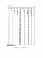
5.1 Background
The data gathered during a field study of a bridge can be used to provide a
realistic estimate of a structure's fatigue life. The stress cycles measured in the field are
stored in a two-dimensional array for each period of collection and data channel in the
Campbell. These arrays are then transferred to Data General microcomputers where the
data is retrieved. The array contains the number of stress range cycles which occurred at
each of the fifty stress range increments and two mean stress levels for each channel and
period.
The stress range level and number of cycles can be used to estimate the fatigue
damage using a Miner's rule summation to calculate the effective stress range as shown
below:
(5.1)
where:
ni =
the number of cycles at stress range
SRi
T = the total number of cycles recorded = L,:ni
Note that mean stress is not included in equation 5.1. Fatigue research on welded structural
steel details indicate that mean stress is not a significant variable. The number of cycles
at the two mean stress levels should be added to obtain ni for each Sm.
The effective stress range represents the stress range which produces the same
fatigue damage as the variable stress cycles measured on the bridge. The estimated fatigue
life in cycles can be calculated using Eq. 5.2.
(5.2)
The constant A in equation 5.2 is obtained from the fatigue life equation of the detail on
the bridge where the stresses were measured. The value of A can be obtained from the
43
44
AASHTO fatigue design stress ranges for redundant load path members at 2 million cycles
in Table 10.3.1A using the equation below:
(5.3)
where SRv is the stress range in Table 10.31A for the detail under consideration.
In order to relate the cyclic life from equation 5.2 into the structure life in years,
an estimate of the number of cycles per year is required. The number of cycles in a year
can be estimated by annualizing the cycles gathered in the field collection period and
adjusting this estimate for past and future traffic volume differences. Methods of adjusting
the number of cycles using traffic surveys and estimated traffic volumes are presented later.
The measured stresses may often be so low that no fatigue damage is occurring
at the location. The stress ranges listed in Tables 10.31A and 10.31B of the AASHTO
Specification for over two million cycles represent the estimated fatigue limit or threshold
stress range of each fatigue category. The values listed in Table 10.31A for redundant
members are based on laboratory studies. The values in 10.31B are reduced stress ranges
to provide increased reliability for non-redundant members. If the largest measured stress
range gathered in the field study is less than the values listed for over two million cycles
for the detail instrumented, no fatigue damage occurred at the detail during the period
the data was collected. If the largest measured stress range is less than or equal to 75%
of the threshold value and the data gathering period is representative of typical traffic, at
least five days of data, then it is reasonable to assume that the location instrumented on
the bridge will not exhibit fatigue cracking. No fatigue life estimate is required since the
fatigue life is infinity. The 75% limit on the threshold stress range suggested above is based
on the authors judgement. Higher cutoffs, but less than or equal to 100% of the threshold,
can be justified if the user is satisfied that present or future loadings will not cause an
increase in the measured stresses. A longer sampling period, for example two weeks versus
one, or sampling another week will allow a more refined analysis and justify an increase in
the percentage of threshold stress range to be used.
5.2 Program RFLO
In order to facilitate reduction of the stress range data gathered in the field, an
additional program is provided. The program title is RFLO. This program is written in
Turbo Pascal. RFLO can be used to plot the stress range and the fatigue damage factor for
45
each channel and collection interval on the screen. In addition, the user can print out the
data for further study and documentation. The program will also create comma separated
files in which the printed data is written to a disk file with each value separated by a
comma. This comma separated file can then be used as input into other programs such as
commercial spreadsheet programs. A detailed description of how to use this program and
interpretation of its output is given in the next section.
Data File : 135.RFL
Save File : C:l35.11
Number of intervals : 7
Interval Length
: 1440 Minutes
Number of channels : 5
SA Max
Channel
Channel
Channel
Channel
Channel
1
2
3
4
5
9.000
9.000
9.000
9.000
9.000
SA Min
0.500
0.500
0.500
0.500
0.500
Interval : 1
Channel : 1
F1 ..SUM MSL vs. SA
F7.SAVE AU.
F2•D.F. VI SA
FS..PRINT ALL
FIGURE 5.1
F4.PRINT
FS..SAVE
ESC ·END
RFLO Input Screen
5.2.1 Using Program RFLO. The program is executed from DOS by typing
RFLO followed by a carriage return. The prompt "Data File:" will then appear on the
screen. Enter the data file you wish to work with by typing in the characters. RFLO
automatically adds the extension RFL. Only files with the RFL extension can be accessed
by this program. The RFL extension was added to your file name in program 21X when
you retrieved the data. After the file name is typed and a carriage return pressed, RFLO
will search the disk for the file and retrieve the header information in the file. The screen
should look like Figure 5.1 after the file has been accessed. The number of channels,
intervals, interval length, and the minimum and maximum stress ranges of each channel
are displayed. Also, the program defaults the save file to File name.11. The numbered
46
extension refers interval and channel. For example, 135.21 refers to the data gathered
during the second interval on channel one. The cursor position is at the bottom of the screen
adjacent to "Interval:". The number of the current interval and channel are displayed. The
data from this interval and channel are the data the program will graph or print out on your
command using the function keys. The interval and channel can he changed by moving the
cursor using the arrow keys and typing in the desired quantities. The save file extension is
automatically changed to match the current values.
The save file is a comma separated file created by RFLO if you press the F5 key.
You can also create comma separated files for all intervals and channels by pressing the F8
key. A printout of the data and an analysis of the data can he obtained by pressing the F4
key. F4 will print out the current interval and channel. The printout for all intervals and
channels is obtained by pressing the F7 key. A typical print is shown in Figure 5.2. The
headings on the printout are defined as follows:
SRL = stress range level
MSL1
=
MSL2
SUM
number of cycles recorded in mean stress level 1
number of cycles recorded in mean stress level 2
=
total number of cycles recorded in both mean stress levels
SR = stress range in ksi for the given SRL
%MSL1
=
percent of the total number of cycles recorded that are in the mean
stress level 1
%MSL2 = percent of the total number of cycles recorded that are in the mean
stress level 2
%ALL
percent of the total number of cycles recorded that are in the particular
SRL
D .F. = damage factor, see Eq. 5.4
In addition to the printing, analysis, and saving functions, the program provides
for a graphical display of the data on the screen. Pressing F1 produces a bar graph histogram of the level of occurrence of the stress ranges. The levels at the two mean stress
levels are added together to produce this plot. Pressing the F2 key produces a plot of the
Interval= 1
Channel= 1
SBL
MSLl
47
MSL2
1
0
2
95
3
23
4
1
5
0
6
0
7
0
8
0
9
0
10
0
11
0
12
0
13
0
14
0
15
0
16
0
17
0
18
0
19
0
20
0
21
0
22
0
23
0
24
0
25
0
26
0
27
0
28
0
29
0
30
0
31
0
32
0
33
0
34
0
35
0
36
0
37
0
38
0
39
0
40
0
41
0
42
0
43
0
44
0
45
0
46
0
47
0
48
0
49
0
50
0
cycles per HoW"s - 67.4
Effective Stress Range =
0
602
400
207
99
53
64
58
13
2
0
0
0
0
0
0
0
0
0
0
0
0
0
0
0
0
0
0
0
0
0
0
0
0
0
0
0
0
0
0
0
0
0
0
0
0
0
0
0
0
SUM
SR
%MSL1
%MSL2
%ALL
D.F.
0
697
423
.38
0
5.88
1.42
.06
0
0
0
0
0
0
0
0
0
0
0
0
0
0
0
0
0
0
0
0
0
0
0
0
0
0
0
0
0
0
0
0
0
0
0
0
0
0
0
0
0
0
0
0
0
0
0
37.23
24.74
12.80
6.12
3.28
3.96
3.59
0
43.10
26.16
12.86
6.12
3.28
3.96
3.59
0
.19
.80
.80
.12
0
0
0
0
0
0
0
0
0
0
0
0
0
0
0
0
0
0
0
0
0
0
0
0
0
0
0
0
0
0
0
0
0
0
0
0
0
0
0
0
.12
0
0
0
0
0
0
0
0
0
0
0
0
0
0
0
0
0
0
0
0
0
0
0
0
0
0
0
0
0
0
0
0
0
0
0
0
0
0
0
0
2~
99
53
64
58
13
2
0
0
0
0
0
0
0
0
0
0
0
0
0
0
0
0
0
0
0
0
0
0
0
0
0
0
0
0
0
0
0
0
0
0
0
0
0
0
0
0
.76
1.14
1.52
1.89
2.27
2.65
3.03
3.41
3.79
4.17
4.55
4.93
5.31
5.68
6.06
6.44
6.82
7.20
7.58
7.96
8.34
8.72
9.09
9.47
9.85
10.23
10.61
10.99
11.37
11.75
12.13
12.51
12.88
13.26
13.64
14.02
14.40
14.78
15.16
15.54
15.92
16.29
16.67
17.05
17.43
17.81
18.19
18.57
18.95
1.58
FIGURE 5.2 Printout from RFLO Program
.38
.45
.42
.39
.74
1.00
.32
.07
0
0
0
0
0
0
0
0
0
0
0
0
0
0
0
0
0
0
0
0
0
0
0
0
0
0
0
0
0
0
0
0
0
0
0
0
0
0
0
0
48
fatigue damage factor versus the stress range. The damage factor is also the last column
of the printout and is defined as:
(5.4)
This term is the function summed in Eq. 5.1, the effective stress range calculation. The
larger values of this damage factor indicate the levels of stress range producing significant
fatigue damage. The two plots, histogram and fatigue damage, can be used to determine
the significance of the measured stress ranges relative to the fatigue calculations. Figures
5.3 and 5.4 show the stress range histograms for all intervals and each relevant individual
interval. Figure 5.5 shows the stress cycles in each interval. Figure 5.6 shows the fatigue
damage for each interval. Most of the fatigue damage occurs at a stress range of 3 ksi.
Intervals 1, 3 and 4 show significantly lower number of stress cycles.
5.3
Calculating Fatigue Life
It is recommended that a minimum of seven days of data be used in assessing a
bridge. This one week period should prevent a biases in the analysis due to daily truck
traffic fluctuations. A more refined analysis is obtained if the number of days of collection
is increased. Based on our experience, however, care should be exercised in extending the
testing for periods more than one week. Daily variations in traffic can be considerable. If,
for example, eight days of data are collected and the repeated day of the week is a low
traffic day, the resulting fatigue life estimate will be biased and possibly unconservative.
Before a fatigue life is estimated, the collected data should be screened to determine if it looks reasonable. The effective stress range for each collection interval of a
channel should be reasonably constant. This daily effective stress range is given in the
printout from RFLO. The number of cycles for each interval for all the channels should
show reasonable correlation. That is, the ratio of the number of cycles between two channels from one day to another should be reasonably constant. If large differences occur that
cannot be explained, then the field test should be repeated to determine the cause of the
differences. Switching transducer is suggested to determine if the differences are caused by
a faulty transducer.
5.3.1 Fatigue Life Calculation Example. The data from a seven-day (one
interval equal to a day) test of an AASHTO category E' fatigue detail are used to estimate
the fatigue life of a bridge. The data was analyzed using a commercial spreadsheet program,
SuperCalc 4. A copy of the SuperCalc template (example.cal) file is provided on a diskette.
49
Stress Range Histogram
--All Intervals--
8c
f:::J
u
u
0
.3+----i..'
50
Cycles per Interval
~~------------------------------------------~
3~+-------~M-------------''
I
c;
~
.! 2400 +----4.:
.E
.....
~
:
1800 .._..........,~_..,._
~
800
0
1
2
J
4
5
8
1
Avwa~
Interval
Figure 5.5
Fatigue Damage Factor
2
a
1.5+--------------~--------~r--------------~-------·------~
00
"u
Dl
D
E 1+---------------
------~~A~·---------------------------~
D
0
CP
:::2
Dl
~ .5 t------.....,.![IIII'IIII'!Y--+-----------\\1~-------i
0
-~------....---------.-----------.---~~!!lii::;-~.......::;::;::;.__j
0
1
2
4
5
8
J
Stress Range-ksi
Figure 5.6
51
The data was first processed through program RFLO to create comma separated
files. The seven files for Channel 1, the channel connected to the transducer at the E'
detail, were loaded into the SuperCalc template. The template was used to analyze the
data and to produce hard copy plots using a pen plotter. The data in Fig 5.2 is one of the
files used. Figures 5.3 through 5.6 were made using this spreadsheet program.
Figure 5.7 shows a printout from the spread sheet program. The number of cycles,
effective stress range, maximum stress range, and the fatigue life based on the effective stress
range cycles are shown.
Fatigue Life Analysis
Load Comma Separated Files from RFLO
Starting at Cell A20
Fatigue Detail Sr
@
2x10 6 cycles: 5.8ksi (enter value)
A: 3.9022e8
Interval
Cycles
Sr Eff.
Max. Sr
1
2
3
4
5
6
7
All
1,617
3,134
1,567
1,328
3,398
3,339
3,575
17,958
1.58
1.64
1.58
1.78
1.72
1.71
1.70
1.68
3.79
5.68
3.79
4.17
4.55
3.79
3.79
5.68
Life-Yrs
167.6
77.8
171.6
143.6
62.0
64.5
61.3
88.0
Graphs
1 - Sr Histogram All Interval
2 - Sr Histogram Ea. Interval
3 - Cycles per Interval
4 -Fatigue Damage Factor
Cycles/Year= 936,381
FIGURE 5. 7
Spreadsheet Output
The values for all the intervals taken together is also shown. The overall values
should be used for the fatigue life calculation. The estimated fatigue life based on the traffic
conditions during the study is 88 years. Since the structure is 35 years old, one estimate of
the remaining fatigue life is 43 years.
52
The calculated remains life of 43 years assumes that past and future traffic volume
and distribution of trucks within the traffic remain stationary. A more realistic estimate of
the fatigue life can be made by using actual historical traffic counts on the roadway. As an
example of the use of measured traffic counts, assume the following traffic data is available:
YEAR
ADT
1953
5,000
1960
1970
7,500
10,000
1975
1980
15,000
20 000
(bridge opening)
This measured traffic data can be used to estimate the traffic for the life of the structure
using a simple compound traffic growth model shown below:
ADTj:::: ADT (1
where:
ADTj =
R
=
+ R)i
(5.5)
ADT after j years
rate of growth per year
In order to use this formula the value of R must be estimated from the measured data. A
SuperCalc spreadsheet was used to determine the best fit R value. This spreadsheet was
also used for some of the ratio calculations. The template file is named fatigue. cal and is
on the diskette provided.
Figure 5.8 shows the absolute error of the predicted ADT versus the measured
values for R from 0.04 to 0.063. The lowest error, best fit R value, is R=0.051. The
estimated fatigue life is sensitive to value of R. Figure 5.9 shows how the predicted fatigue
life changes with R, with all other parameters remaining constant. Figure 5.10 shows the
53
!nfluence of Growth Value on Error in ADT
Capacity=-50,000, Cycles/Day(Field Test)=2565
100.0"' ..,......--------~--------------------,
1-
st
80.0"' +-------------------------------1------i
.s
L.
e
~
"
,
60.0" +-'<---------------------+------------1
~
:l
0
~
40.0"' +------------"'...---~-------+-------------------------l
20.0" +-----.-------------.-----.-------...-----1
4.0X
4.5"
5.o"
5.5"
e.ox
8.5"
Estimated Growth Value-R
Figure 5.8
Influence of Growth Value on Fatigue Life
Capacity=50,000, Cycles/Day(Field Test)==2565
94..,......---------------------------r---~
~~+----------------------------~---0
'i"
¢.1
~
EM+_------------------------~----------~-1
:.::;
~
¢.1
~~+----~------------------r--------------·-------~
¢.1
:l
01
:.::;
~74+------------~------------
69~---------T-------~---------,------~----
,04
.045
.05
.055
Estimated Growth Value-R
Figure 5.9
.06
.065
54
ADT Estimate
.051
50000C--.-------------...,
--
U•awred
E•tlmated
41000
~
,._L--+-~---------------~
I
2~0+-----+-----------
14000T---~------------------------------_,
~+L-----,-------r------~------~-----4
1150
1110
2030
2110
2070
2150
Year
Figure 5.10
'
Fatigue Life Estimate-Years
.051
2~-------------------------T-------------~
u
:su
u
:J
C7l
:p
0
u...
....0
1
i
c
0
:p
u
~
.5
1110
2070
2030
Year
Figure 5.11
2110
2150
55
estimated ADT versus the ADT calculated from Eq. 5.5 using R=0.051. The agreement is
seen to be fairly reasonable.
In addition to employing the measured ADT, a capacity limit upon the ADT
should be used. This is necessary to prevent the ADT predicted from Eq. 5.5 to exceed
the absolute capacity of the highway. This limit can be obtained from highway rating
procedures or estimated based on observed conditions at peak traffic hours. An estimated
maximum value of 50,000 was used in Figs. 8 through 10. The resulting fatigue life
prediction is shown in Fig. 5.11. The estimated end of life is 2030, a fatigue life of 77 years.
The ADT limit of 50,000 is reached after 47 years, the year 2000. The life estimates assume
the ratio of stress cycles to number of vehicles remains constant over the life of the bridge.
The ratio used in the spreadsheet analysis is based on the average number of stress range
cycles from the seven-day field test, 17,958/7 = 2565 cycles divided by the estimated ADT
for 1988 for an R value of 0.051. The estimated 1988 ADT is 28,514 which results in 0.08996
stress cycles per vehicle. This ratio is extremely important in determining the estimated
fatigue life. Figure 5.12 shows how the fatigue life estimate changes as the average number
of stress cycles per day is changed. A low of 1,317 and a high of 3,575 were measured
during the field test. The result is a two-fold difference in fatigue life. A field test duration
should be long enough to insure that daily variations in traffic do not cause the number
stress cycles counted to be biased.
The last figure, Fig. 5.13, shows how the estimated fatigue life varies with the
estimated ADT capacity. In this example, capacities above 75,000 do not significantly
change the fatigue life since the majority of the fatigue damage occurs before the ADT
reaches this capacity.
The estimated life for this example, based on steady state number of fatigue
cycles equal to the average measured in the field test for the life of the bridge, is 88 years.
Using a best-fit R of 0.051 and a ADT capacity of 50,000 yield a life of 77 years. Using
the same value of R and ADT capacity, but increasing the number of stress cycles per
day to the maximum in the field test yields a fatigue life of 62 years. Therefore, based on
these estimates, the Category E' detail in the example bridge would be expected to have
significant cracks after a life of 60-80 years, or between the years 2013 and 2033.
The bridge should be inspected and retrofitted prior to this date. Further future
field studies can be performed to redefine the number of stress cycles and effective stress
range produced by traffic to compare with the values estimated in this analysis.
56
Influence of Cycles/Day From Field Test
R==0.51, Estimated AOT Capcity=SO,OOO
1~~----------------------------~~-------------------~
r!
~ 120
'i
!I
~E
I.
:p
:
" 100 r---··- --- -- LtJ
!
~
::J
l
Q)
-~----- -
.2-
80 [ '
~
....
-
___,i
I
____ J
I
80
1 JOO
----,.----- - ---- -,-- 1800
2300
·r2800
-- -,JJOO
3800
Stress Cycles per Day From Field Test
Figure 5.12
Influence of ADT Capacity on Fatigue Life
R=0.51, Cycles/Doy(Field Test)=2565
------------,
110,--
s
~
I
J
100.l_
i\
~E 90L\_
:p
t!l
~
"&.
~
~
I
j
I
'
!
I
80+--
I!
i
70+---1
sot----30000
i
·-·----·
60000
-· ....
I
90000
Estimated ADT Capacity
Figure 5. 13
-
~
120000
APPENDIX
DATA GENERAL PROGRAM LISTING
PROGRAM CR21X(INPUT,OUTPUTl 1
I AUTHOR : BAHRAM ALEC TAHMASSEBI
I
DfVEIOPED AT FERGUSON STRUCTURAL ENGINEERING LABORATORY
I
OALCONES RESEARCH CENTER
I
UNtVERSilY OF lEXA~ AT AUSTIN
I
VERSION 1 1
7-1-88
I
.. ; . .
. . . . . . . . . .
C014ST
f'l
F2
F3
F4
F5
F8
F7
F8
F9
FlO
59
60
61
62
63
64
65
68
67
68
UP_ARROW
DN_ARROW
LT_ ARROW
RT_ARROW
= 80
= 75
77
CARRIAGE
ESC
DEL
=1
= 83
::
72
=
::
28
DEFAULT_DRIVE
ERR_ROW
ERR_COL
=
=
:;
·c·
I
25
0
FKEY_ROW :: 24
MESSAGE_ROW
FILE_ROW
FILE_COL
TABLE_START_COLUMN
TABLE_START_ROW
ACTIVITY_MESS_ROW
22
22
10
8
2
24
= 650
MAX_PL~_POINTS
MAX_IN~RVALS
=
DEFAULT_SG_EXCITATION
DEFAULT_SG_RANGE
DEFAULT_OT_EXCITATION
DEFAULT_DT_RANGE
HI LITE
Bl
. . . . . . . . . . . . .
. .
I
I
I
I
I
. I
: $40
= $83
14
4000
11
4000
13
4 000 m i I i v o I t a :
5 milivolt range
4000 milivolts =
50 mi 1 ivol t range
4 vo I t s
4 volta
I
................................................. I
TYPE
MESSAGE
MESS_ARRAY
REGISTERS
CHANNEL_RECORD
= STRING[80l 1
= ARRAY[0 .. 10l OF MESSAGE ;
= RECORD
AX, BX, CX, OX, BP, Sl, 01, OS, ES, FLAGS : INTEGER
END 1
RECORD
10
INTEGER ;
TRANSDUCER
INTEGER ;
I 1 = sg , 2 = dt , 0 = undefined I
TRANSOUCER_COL
INTEGER 1
DETAIL
INTEGER 1
DETAIL COL
INTEGER 1
EXCITATION
INTEGER 1
EX_CHANNEL
INTEGER 1
ROW
INTEGER 1
SR_MAX
REAL
SR_MIN
REAL
S_CALIB
REAL
VI
co
MVPERV_CALIB
OFFSET
MULTIPLIER
ZERO , CURRENT
HI
, LO
RANGE
VAL ARRAY
PLOT_ARRAY
PLOT_CHANNELS
T !ME
END 1
ARRAY I I
REAL
REAL
REAL
REAL
REAL
INTEGER
81 OF RECORD
INDEX
VAL
END 1
1 NTEGER
REAL
ARRAY!I .. MAX PLOT POINTS! OF REAL
ARRAY£1..81 OF INlEGER ;
RECORD
HOUR
: INTEGER
MINUTE : INTEGER 1
SECOND : INTEGER
END 1
1
................................................ I
VAR
CURR PAGE
MESS
ROW , COL
CUR_ROW , CUR_COL
COLOR
KEY_PRESSED
KEY
BYTE
MESSAGE
INTEGER
BYTE
INTEGER
BYTE
BYTE
FNAME
PF_FOUND
NEW_PF
SOLID_LINE
ERRORS
DONE
SCREEN_SET
ACO_SCREEN_SET
LAST_NUM
LAST_CHAR
SERIAL_PORT
CH
CHAR_AVAIL
FULL_DUPLEX
LINE , MODEM
STRING! SOl
BOOLEAN
BOOLEAN
MESSAGE
MESS_ARRAY
BOOLEAN
BOOLEAN
BOOLEAN
REAL
CHAR
TEXT
CHAR
BOOLEAN
BOOLEAN
INTEGER
BYTE
DESCRIPTION_FILE
DATA_FILE
TRUCK_OATA
STK_FILE
TEXT
TEXT
TEXT
TEXT
REGS
REGISTERS
BAUD
PARITY
NSTOP
NOATA
INTEGER
INTEGER
INTEGER
INTEGER
CANCELLED
EMPTY
PROGRAMMED
ZEROED
BOOLEAN
BOOLEAN
BOOLEAN
BOOLEAN
TITLE
TABLE_ TOP
TABLE_TOP_2
TABLE_MIDOLE
TABLE_LINE
TABLE_BOTTOM
MESSAGE
MESSAGE
MESSAGE
MESSAGE
MESSAGE
MESSAGE
FKEYS
S_CALIB_MESSAGE
MVPERV_CALIB_MESSAGE
MESSAGE
MESSAGE
MESSAGE
I
\.11
\0
•
MESSAGE
MESSAGE
MESSAGE
MESSAGE
MESSAGE
MESSAGE
MESSAGE
MESSAGE
;
ARRAY{1 .. 81 OF CHANNEL_RECORD
ARRAY! L 81 OF REAL ;
ARRAY{ 1 .. 8! OF INTEGER •
ARRAY! 1. 201 I OF MESSAGE
TRANS MESSAGE
DETAIL MESSAGE
SR_MAX=MESSAGE
S R_M I N__ME S SAGE
SEND_MESSAGE
READ_MESSAGE
_DEFINE MESSAGE
'EMPTY_MESSAGE
CHANNEL INFO
RAW_VOLTAGES
ACTIVE CHANNELS
RAIN_ARRAY
•
•
•
•
SRMAX
ARRAV£1 .. 71 OF REAL
, SRMIN
1
'
CURRENT TIME
CR2 1 X_ TIME
START_TIME
DAYS ELAPSED
INTERVALS_ELAPSED
RAIN_INTERVAL
TIME
TIME
TIME
INTEGER
INTEGER
INTEGER
'
CURRENT_CHANNEL
CURRENT __ F I ELD
INTEGER
INTEGER
•
MEANS_BINS
AMPLITUDE_BINS
LOW_L IMI T
HIGH_LIMIT
PEAK_VALLEY_DISTANCE
CR_LF
CR
CHANNELS
CR21X_CHANNELS
DSP
MPTR
NSCAN
INTEGER
INTEGER
INTEGER
INTEGER
REAL
STRINGI21
CHAR
INTEGER
INTEGER
INTEGER
INTEGER
INTEGER
PLOT DATA
NPOINTS
ARRAY[l .. 81 OF PLOT_ARRAY ;
INTEGER
!
---
--------
---
----- ----------
---------------------------
PROCEDURE CLS CSTROW,STCOL,ENDROW,ENDCOL,COLOR : BYTE
VAR
REGS : REGISTERS
BEGIN
WITH REGS DO
BEGIN
Ax : = so roo
BX := CCOLOR * 256) + 0
CX := (STROW * 2.56) + STCOL 1
OX := (ENDROW * 2.56) + ENDCOL
END ;
INTR(S10,REGSJ
END :
I · ---- ----
----
l
----
-l
;
---- ---- --- ----- -----------------------------------------1
PROCEDURE SCROLL_UP (STROW,STCOl,ENDROW,ENDCOl : BYTEJ
VAR
REGS : REGISTERS
BEGIN
WITH REGS DO
BEGIN
AX : = $0601
BX
10700
CX := (STROW * 256) + STCOL 1
OX := CENDROW * 2.56) + ENDCOL
END ;
INTR(SlO,REGSl
END :
1- ----
"'
0
--
;
--- ---------- ---- ----------------------------------1
PROCEDURE SCROLL_DN (STROW,STCOL.ENDROW,ENDCOL
VAR
REGS : REGISTERS
BEGIN
WITH REGS DO
AEGIN
$0 7 0 1
AX
BX
SOIOO
ex : = (STROW "' 256) + STCOL 1
OX
= IENDROW * 256) + END COL
END ;
NTR(SlO,REGSl
END
[ - - - -- -
----
BVTEl
1
- --- ------------ ---- --------------------------1
PROCEDURf CURSOR IROW.COL
BYTEJ ;
VAR
REGS : REGISTERS
BEGIN
WITH REGS DO
BEGIN
AX:= S0200;
BX := CURR PAGE
* 256
DX := CROW-,. 256J + COL
END ;
INTRIS10,REGSJ
END :
1---- --- -- --- ----- ----------------------- ----------------------- -------1
PROCEDURE SEL_PAGE :
VAR
REGS : REGISTERS
BEGIN
REGS.AX :
15 * 256)
INTR(STO,REGSl
END :
-
-
-
-
- -
---- -
+
CURR_PAGE
1
---------- -------------------------------------------}
PROCEDURE GETC CVAR KEY : BYTE) 1
VAR
REGS : REGISTERS
BEGIN
REGS_ AX : = $0000
INTR(S16,REGSl
1
KEY
:: REGS.AX AND SOOFF ;
KEY_PRESSED := (REGS AX AND SFFOO) OIV 256
END :
(- -- - -------- --- - --------------------- ---------------------------------1
PROCEDURE WRCOL(ROW, COL, COLOR
INTEGER 1 MESS : MESSAGE)
VAR
, J, K : INTEGER
REGS
: REGISTERS
BEGIN
K : = COL ;
J := OROCMESSIOJ) ;
FOR I
= 1 TO J 00
BEGIN
CURSORCROW,K)
WITH REGS DO
BEGIN
AX
( 9 * 256) + OROCMESSI ll) 1
BX
CCURR_PAGE "' 256) + COLOR 1
ex
sooot ,
INTR
IO,REGS)
END
!-
END
END
K
~-------------
K
+
1
1
"'
1-'
_
------ --------------------- -----------------------}
PROCEDURE GET_CURSORCVAR ROW, COL
BYTE)
VAR
REGS
: REGISTERS
BEGIN
REGS AX :~ $0300 :
REGS BX :
CCURR PAGE * 256) + 0 ;
INT~($10,REGSl
,ROW:= CREGS.DX AND SFFOOl DIV 256
COL := REGS.DX AND SOOFF
fND :
--
------
·-
--
--
-----
1
C)'\
N
1
------------ ------------------------)
PROCfDURE VDO STATCVAR MODE. WIDTH, PAGE : BYTE)
VAR
REGS
: REGISTERS
BEGIN
SOFOO ;
REGS. AX :
INTRCSIO,REGSl ;
MODE
LO<REGS.AX) ;
WIDTH :::: HICREGS.AX)
PAGE
HICREGS.BX)
END :
[-- ----
1
----- ------ ------------------- --------------------------------1
PROCEDURE VDO_MODECMODE : BYTE)
VAR
REGS
: REGISTERS
BEGIN
REGS.AX := COOOO + MODE
INTRCS10,REGSl ;
END ;
!---
------
-------------
-------------
FUNCTION NUMERICCCH : BYTEl • BOOLEAN
BEGIN
NUMERIC :::: FALSE 1
IF (CCH > 48) .AND CCH <= 57))
THEN NUMERIC := TRUE
[--~NO
I
---
-----
-----
------
------
--------------
------------
--1
1
----------------------------
---------------1
FUNCTION SPECIALCCB : BYTE)
BOOLEAN
BEGIN
SPECIAL : = FALSE 1
IF
( CB = 13) OR CB ::: 44) OR
CKEY_PRESSEO
UP _ARROW) OR CKEY_PRES ED = DN_ARROWl OR
LT_ARROW) OR CKEY_PRES ED = RT_ARROWl OR
CKEY_PRESSED
F2) OR
<KEY PRESSED
Fl> OR CKEY_PRESSEO
CKEY_PRESSEO
CKEY-PRESSED
F3l
OR
FO OR
(KEY-PRESSED
OR
CKEY_PRESSED
F6l OR
F5l
CKEY_PRESSEO
OR
FB> OR
<KEY-PRESSED
F7l
CKEY_PRESSED
F9l
OR
FIOl OR
~~~~=~~~~~~g ESC> OR CKEY_PRESSED DEL>
THEN SPECIAL : = TRUE
END
(
--
----- ----- ------------- ---------------------------------------1
PROCEDURE DISP_ERRCERR : INTEGER>
VAR
CUR_ROW , CUR_COL : BYTE ;
BEGIN
GET_CURSORCCUA_ROW.CUR_COLl 1
WRCOLCERR_AOW.EAR_COL,4.ERRORSIERRll
WRCOL<ERR_ROW.ERR_COL.8.ERRORSIOJl 1
CURSOACCUR_ROW.CUR_COll
END 1
(- ------ ----- -------------------- ----------------------------------------1
PROCEDURE GETDtVAR DIG :
VAR
DONE
B()OLFAN
Kl Y
INTEGER)
BYT
fll 1,1 N
llON(
IALSt ;
WHit@ NOT DONE DO
HFGIN
GfTCCKEYl ;
IF tNUMERICtKEYll
THEN
BEGIN
DONE :
TRUE ;
DIG
: ORDCCHRCKEYll - 48
END
ELSE IF SPECIALCKEYl
THEN DONE := TRUE
ELSE DISP_ERRC5l
ENO
END :
!--
----
-----
------------
------
------------
FUNCTION LEGAL_CtCH : BYTE) : BOOLEAN
BEGIN
LEGAL_C
FALSE ;
F ((CH > 48) AND CCH <=57)) OR
((CH >= 95) AND tCH <= 123ll OR
CCH = 33) OR
CCH = 125l OR
THEN LEGAL_C := TRUE
!-- END ----
---
--------------------------)
90))
C CCH >" 6 4 l ANO CCH <
( ( CH >= 35l ANO CCH <= 39))
126)
CCH
--- _ --------------------------------PROCEDURE GETNAM 1
VAR
CB
, ROW , COL
BYTE
INTEGER
I , FLEN . ELEN
BOOLEAN
DONE
BOOLEAN
EDONE , FDONE
STRING! SOl
NAME
BEGIN
GET_CURSORCROW.COLl :
FOR I
:= 3 TO 50 DO NAMEIIJ : = ' '
1
DONE
= FALSE ;
FDONE
: = FALSE ;
NEW_PF
FALSE ;
:= 0 ;
FLEN
ELEN
:= 0 ;
WHILE NOT DONE DO
BEGIN
:= 0
;
ELEN
EDONE := FALSE :
WHILE NOT FDONE DO
BEGIN
GETCtCBl ;
IF LEGAL_CCCBl
THEN
BEGIN
WRCOLCROW,COL,14,CHRCCBll
COL : = COL + 1 ;
CURSORCROW,COLl ;
FLEN := FLEN + 1 ;
NAMElFLEN+21 := CHRCCBl
IF FLEN = 8
THEN
BEGIN
FDONE := TRUE ;
;
NAMEIFLEN+3l :=
WRCOL CROW, COL , 1 4, ' _ ' l
COL : = COL + 1 ;
CURSORCROW,COL) ;
END
END
ElSE
OR
OR
-------------1
0'\
w
0\
IF (FLEN > Ol AND <CB = 46l
THEN
BEGIN
FDONE := TRUE
WRCOL CROW, COL , 1 4, ' . ' l
COL : = COL + 1
CURSORCROW,COLJ
NAMEIFLEN+31 := ' . •
END
ELSE
IF CCB = 8l AND CFLEN > OJ
THEN
BEGIN
COL : = COL - 1
WRCOLCROW,COL, 14,' 'l
CURSORCROW,COLJ
FLEN := FLEN- 1
END
ELSE
IF SPECIALCCBl
THEN
BEGIN
FDONE := TRUE
EDONE := TRUE
DONE
:= TRUE
ELEN
:= 3 :
NAMEIFLEN+41
= •• 2.
1•
::
NAMEIFLEN+5l
:: • X •
NAMEIFLEN+61
END
ELSE DISP_ERRCll
END :
WHILE NOT EDONE DO
BEGIN
GETCCCBl ;
IF LEGAL_CCCBJ
THEN
BEGIN
WRCOLCROW,COL, 14,CHRCCB)l
COL : = COL + 1
CURSOR<ROW,COL)
ELEN := ELEN + 1
NAMEIFLEN+3+ELENJ := CHRCCBJ
IF ELEN = 3
THEN
BEGIN
EDONE := TRUE
DONE
: = TRUE
END
END
ELSE
IF SPECIAUCB)
THEN
BEGIN
EDONE :: TRUE
DONE
::: TRUE
IF ELEN :: 0
THEN
BEGIN
ELEN
:= 3 1
NAMEIFLEN+4J := '2' 1
NAME(FLEN+5J := '1'
NAMEIFLEN+6l := 'X'
END
END
ELSE
IF CCB = 8 l
THEN
IF ELEN > 0
THEN
BEGIN
COL : = COL - 1
WRCOLCROW,COL,14,' 'l
CURSORCROW,COLl
ELEN := ELEN- 1
+:--
1
END
ELSE
BEGIN
COL := COL 2
WRCOLCROW,COL,14,'
CURSOR(ROW,COLl
FDONE := FALSE
FLEN :: FLENEDONE := TRUE
END
ELSE DISP_ERRC1)
r
END
END :
IF FLEN > 0
THEN
BEGIN
NEW_PF
= TRUE
P F _FOUND = FALSE
;
NAMEIFLEN 3 l : = •
NAME I 0 I : CHRCFLEN+ELEN+3) 1
FNAME!Ol
= NAME [ 0 I 1
FNAME!1l
= DEFAULT_DRIVE :
FNAME!2l
FOR I : :
=T~:~R~CNAME!Oil DO FNAME! II
END
END
I----- -----
------
------
------ -------
.
)
;
"""'
:=
NAME [ I I
--------------------------
-
-------1
PROCEDURE GETNUMCVAR NUMBER : REAL 1 WL. FL : INTEGER)
VAR
ENTRY
ARRAY£1.101 OF CHAR 1
INTEGER ;
I
• J
WHOLE , FRAC
REAL 1
MUL
WLEN , FLEN
INTEGER
BOOLEAN
DONE , WDONE
FDONE
BYTE ;
CB
CH
CHAR 1
ROW , COL
BYTE ;
BEGIN
GET_CURSOR<ROW,COLl ,
FOR I := 1 TO 10 DO ENTRY!II :: ' ' 1
WLEN := 0 ;
IF (WL > 0) THEN WDONE := FALSE ELSE WDONE := TRUE 1
DONE
: = FALSE ;
WHILE NOT DONE DO
BEGIN
FLEN :
0 ;
IF FL > 0 THEN FDONE := FALSE ELSE FDONE := TRUE 1
WHILE NOT WDONE DO
BEGIN
GETC<CBl ;
IF NUMERICCCB>
THEN
BEGIN
WLEN := WLEN + 1 1
ENTRY!WLENJ := CHRCCB) ;
WRCOLCROW,COL,14,ENTRYCWLENI)
COL :: COL + 1 ;
CURSORCROW,COL) 1
IF WLEN = WL THEN IF FDONE THEN BEGIN
WDONE := TRUE 1
DONE
: = TRUE
END
ELSE BEGIN
WOONE := TRUE ;
WRCOL (ROW, COL, 1 4, '
COL : = COL + 1 1
CURSOR< ROW, COL)
END
END
ELSE IF SPECIAL<CB)
THEN BEGIN
WDONE := TRUE
' )
0'\
V1
f
FDONE := TRUE 1
DONE
: = TRUE
END
ELSE IF CCB = 8l AND <WLEN > Ol
THEN BEGIN
COL : = COL - 1 ;
WRCOU ROW, COL , 1 4 , ' ' l
CURSORCROW,COLl 1
WLEN : = WLEN - 1
END
ELSE IF CCB = 46) AND CWLEN > Ol
THEN BEGIN
IF (FL > Ol
THEN BEGIN
WRCOL<ROW,COL, 14,'. 'l
COL :: COL + 1 1
CURSORCROW,COLl
END 1
WDONE :: TRUE
END
ELSE OISP_ERR<Sl
END ;
WHILE NOT FDONE DO
BEGIN
GETCCCBl ;
IF NUMERICCCBl THEN BEGIN
FLEN := FLEN + 1 1
ENTRY!WLEN+FLENI :::: CHRCCBl 1
WRCOLCROW,COL,14,ENTRYlWLEN+FLENll ;
COL : = COL + 1 1
CURSOR<ROW,COLl ;
IF FLEN ::: FL THEN BEGIN
FDONE := TRUE 1
DONE
:: TRUE
END
END
ELSE
IF SPECIAL<CBl
THEN BEGIN
FDONE : = TRUE 1
DONE :: TRUE
END
ELSE
IF CCB :: 8 l
THEN
IF FLEN > 0
THEN
BEGIN
COL :: COL - I 1
WRCOL CROW, COL, 1 4, ' ' l
CURSORCROW,COL) 1
FLEN ::: FLEN- 1
END
ELSE
BEGIN
COL := COL - 2 ;
WRCOL CROW, COL , 1 4 , '
' l
CURSORCROW,COLl ;
WDONE := FALSE 1
WLEN := WLEN - 1 ;
FDONE :::: TRUE
END
ELSE OISP_ERRC5l
END
END 1
IF CWL > Ol AND CWLEN > 0)
THEN
BEGIN
J ::: WLEN ;
WHOLE := 0.0
MUL :: 1. 0 ;
WHILE J > 0 DO
1
;
0'1
0'1
1
BEGIN
WHOLE :=WHOLE + (TRUNC(ORD(ENTRY!Jll-48ll*MUL
MU L : = MU L * 1 0 0 ;
J
:
= J
I
END;
FRAC:cOO
MUL := 10_0
J :
WLEN + 1;
WH I Lf: ( J < = WLEN+FLEN l DO
BEGIN
FRAC : FRAC + rTRUNC(ORD(ENTRY!Jll-48))/MUL
MUL := MUL :o. 10 0 :
J
END :
I
----
END :
NUMBER :
LAST NUM
END : -
:
J
+
1
I
WHOLE + FRAC
= NUMBER ;
---------
------------
------------
----------------------)
FUNCTION F_TO_A( VLU : REAL ; WL , FLEN : INTEGER) : MESSAGE ;
VAR
SIGN , I , J • K , WLEN
: INTEGER ;
TEMPI , TEMP2 , FACTOR
ALPHA , ALPHA2
MESSAGE
BEGIN
SIGN
:= I ;
IF VLU < 0_0 THEN BEGIN
VLU
:=- VLU
SIGN : = -I
END :
TEMPI
VLU ;
WLEN
:= 0 ;
WHILE NOT (TEMPI < I .OJ DO BEGIN
TEMPI:= TEMPI I 10_0
WLEN
:= WLEN + 1
ENi:>
TEMPI := VLU :
TEMP2
= VLU ;
FOR J
I TO WLEN 00 BEGIN
K
:
=
J
'
FACTOR := LO ;
WHILE K < WLEN DO BEGIN
FACTOR := FACTOR * 10_0
K
:=
K
+
1
1
END ;
TEMPI := TEMP2 I FACTOR 1
ALPHAfJJ := CHRCTRUNCCTEMP1l+48) 1
TEMP2 := TEMP2 - (fACTOR * TRUNCCTEMP1))
END :
IF WLEN
0
THEN BEGIN
FOR J := 1 TOWL DO
BEGIN
WLEN := WLEN + 1 ;
ALPHA[WLENJ := '0'
END
END ;
ALPHA[WLEN+1l :
'
;
FOR I := 1 TO FLEN DO BEGIN
TEMP2 := TEMP2 :0. 10.0 1
ALPHA!WLEN+1+1l := CHRCTRUNCCTEMP2l+48l 1
TEMP2 := TEMP2 - TRUNC(TEMP2l
END :
ALPHA!Ol
CHR(WLEN+1+FlENl ;
F SIGN
1 THEN BEGIN
FOR I := CWLEN+1+FlENl DOWNTO 1 DO ALPHAII+IJ := ALPHAIIJ
ALPHA£11 :
'-' 1
ALPHA!OJ := CHRCWLEN+1+FLEN+1l
END ;
- 1
IF SIGN
::;;: 2
THEN
ELSE
1
"'
--..1
WHilE IIALPHAf I I
'0') AND CALPHA£1+11 = 'O'll DO I := I + 1
IF SIGN = 1
THEN J : = 2
ELSE J : = 1 ;
FORK:= J TO OROIALPHA(Oll DO ALPHA!Kl := ALPHACK+I-JJ
ALPHA!Ol
CHRIORDCALPHAfOil + J - ll
f
I
:
J
:
0\
co
.
I
;
WHILE ALPHA£11
=
WI.
I
+
>
1
'
DO I
:=
I
+ 1 ;
;
FORI
ITOJDOALPHA2[1J:::'
1
FOR I:= 1 TO ORDIALPHA{OJ) DO ALPHA211+Jl
ALPHA2f01
CHRIORDIAlPHAfOll + J) 1
F_TO_A
AlPHA2 ;
END ;
( --
r
- --
:=
ALPHAIII
1
----- ---- -------- ---------------------------- -----------1
FUNCTION I_TO_AI IVLU
INTEGER> : MESSAGE 1
VAR
, J , K , WLEN
: INTEGER
SIGN
,
TEMP 1 , TEMP2 , FACTOR
INTEGER
ALPHA : MESSAGE ;
BEGIN
IF IVLU < 0 THEN BEGIN
IVLU := - I VLU
SIGN := -I
END ;
0 THEN BEGIN
IF I Vl U
ALPHA£01 := CHR ( 1 l
ALPHA£11 := ' 0 ' ;
I_TO_A
:= ALPHA
END
ElSE BEGIN
TEMPI : = IVLU ;
:= 0 ;
WlEN
WHILE NOT (TEMP 1 < 1 l 00 BEGIN
TEMPI:= TEMPI DIV 10
WLEN
:= WLEN + 1
END 1
TEMPI :
I Vl U
TEMP2 : = I VLU ;
FOR J := 1 TO WLEN DO BEGIN
K
:
=J
1
FACTOR := 1 1
WHILE K < WLEN 00 BEGIN
FACTOR := FACTOR a 10
K
:: K +
1
1
END ;
TEMPI :: TEMP2 DIV FACTOR 1
ALPHAIJJ :: CHRCTEMP1+48l ;
TEMP2 := TEMP2 - (fACTOR a TEMPI)
END
END :
!-
-
--
-----
--
--
END 1
ALPHA I 0 l : = CHRCWLEN) ;
IF SIGN = -1 THEN BEGIN
FOR I:= WLEN DOWNTO 1 00 ALPHA(I+II
ALPHAfll :: '-' 1
ALPHAlOI := CHRCWLEN+t)
END 1
I_TO_A
:: ALPHA
---------------------------------------------------------1
FUNCTION A_TO_FIASCII
MESSAGE) : REAL
VAR
I , J
K , L , M : INTEGER ;
INDEX
INTEGER ;
SIGN
REAL
;
WSTRG
STRINGf51
:=
ALPHAIII
FSTRG
WHOLE
FRAC
FRACR
EMP
IN
J
:
~
K
:
=
STRING£5
INTEGER
INTEGER
REAL
INTEGER
il
;
SIGN : = 1 0 ,
IF ((ASCI I[JJ = '+'l OR (ASCI I(JJ = '-')l
THEN
BEGIN
' THEN SIGN := -1 0
IF ASCII[JJ
J
:
END :
0
=
J
+
1
;
DO
WHILE ASCI I!Jl <>
BEGIN
K : = K + 1 ;
WSTRGlKI
=ASCI llJI
=
J
J
+
1
END :
WHOLE : = 0
FOR L : = 1 TO K DO
BEGIN
TEMP := ORO(WSTRGllll - 48 ;
FOR M : = L TO K
1 DO TEMP : = TEMP
WHOLE :=WHOLE + TEMP
END :
K
J
+
0
;
*
10 ;
*
10
WHILE (J <= OROlASCII[Olll DO
BEGIN
K : = K +
,
FSTRG!Kl := ASCII[JJ
J
:
=
J
+
1
END :
FRAC
:= 0 ,
FOR L = 1 TO K DO
GIN
ORDCFSTRG[LJ)
48 ;
TEMP
FOR M := L TO K - 1 DO TEMP
FRAC
:= FRAC
+ TEMP
END ;
FRACR := FRAC :
FOR L
1 TO K DO FRACR := FRACR I
A TO F : = SIGN " (WHOLE + FRACRl
END -~ -
:=
!
---
!----·--
------------------
--------------
--
:=
TEMP
10.0
----------------------
-
-----------------1
----------------------------------------1
BOOLEAN
FUNCTION COM_READY
VAR
LINE,
BYTE
GER ;
I
• J
STERS
REGS
AFGIN
COM READY : = FALSE
= t0300 ;
REGS.AX
REGS.DX :
$0000 ;
INTR($14,REGSl ;
HI(REGS.AXJ
LINE
MODEM
:
LOlREGS AXl
WRITELN ('COM READY:
LINE=
',LINE:3,' MODEM
',MODEM: 3)
LINE :
LINE AND $01
WR I T E LN ( L I NE ) ;
END
F CliNE AND $01) = 1
THEN COM_READY := TRUE
-------
- ----------------- -- -----------------------------------1
0'
\0
PROCEDURE COM_PAR(BAUD , PARITY , STOPS • NOATA
VAR
PARAMETERS : BYTE
I , J : INTEGER ;
REGS
: REGISTERS
BEGIN
PARAMETERS :
0 ;
CASE BAUD Of
110
PARAMETERS := SOO
150
PARAMETERS := $20
300
PARAMETERS := $40
600
PARAMETERS := 160
1200
PARAMETERS
180
2400
PARAMETERS := SAO
4800
PARAMETERS := SCO
9600
PARAMETERS := lEO
END : I case l
CASE PARITY OF
0
PARAMETERS := PARAMETERS + SOO
1 : PARAMETERS := PARAMETERS+ 108
2 : PARAMETERS
PARAMETERS + 118
END : ! case I
CASE STOPS Of
1 : PARAMETERS := PARAMETERS + 100
2 : PARAMETERS := PARAMETERS + 104
END : I case l
CASE NDATA Of
7 : PARAMETERS := PARAMETERS + $02
8 : PARAMETERS := PARAMETERS + 103
END : I case I
REGS AX := $0000 + PARAMETERS ;
REGS.DX := $0000
INTR!S14,REGS)
END :
!
---
---
--
----
----
----
INTEGER)
-...)
0
none
odd
even
---------------------
PROCEDURE SET_PAR ;
BEGIN
CURR_PAGE : = 1
SEL_PAGE:
CLSC0,0,24,79,0J :
WRCOL(1,40,3.'Communica tions Parameters')
WRCOLI2,40,3,'
')
WRCOLI24,1,3,'F1 :Baud
F3: Parity
WRCOLI5,40.3,'Baud Rate= 'J
CASE BAUD Of
110 : WRCOLC5,52,3,'110 ')
150
WRCOL(5,52,3,' 150 ')
300
WRCOU5,52,3,'300 ')
600
WRCOU5,52,3,'600 •;
1200
WRCOLC5,52,3,'1200')
2400
WRCOLC5,52.3,'2400'J
4800
WRCOL(5,52,3,'4800'J
9600
WRCOL(5,52,3,'9600')
END : I case I
WR C 0 L ( 6 , 4 0 , 3 , ' P a r i t y = ' ) ;
CASE PARITY OF
0 : WRCOLI6,49,3.'None'J
1 : WRCOU6,49,3,'0dd 'J
2 : WRCOLI6,49,3, 'Even')
END ; I case I
WRCOU7,40,3,'Siop Bits
'l
CASE NSTOP OF
1 : WRCOL ( 7, 52, 3. ' 1 'J ;
2
WRCOU7,52,3. '2'J :
END , I case l
WRCOU8,40.3. 'Data Bi Is = ')
CASE NDATA OF
7 : WRCOL ( 8. 52 , 3, '7 ' J
8 : WRCOL(8,52,3,'8'J
END ; I case I
----------------------1
1
1
F5
Stop Bit&
f7
Data Bits
ESC= Exit')
KfY := 127 ;
GETC(
Y} :
WHilE
Y PRESSED <> ESC DO
B[GINCASE KFY_PRESSED OF
F 1
BEGIN
CASE BAUD OF
150
110
BAUD
300
1!i0
BAUD
600
300
BAUD
1200
600
BAUD
1200
BAUD
2400
4800
2400
BAUD
9600
4800
BAUD
1 10
9600
BAUD
END : I c se 1
CASE BAUD OF
110 : WRCOL(5,52,3, '110 'J
150 : WRCOLC5,52,3, '150 ')
300 : WRCOLC5,52,3, '300 ')
600 : WRCOLC5,52,3, '600 ')
1200 : WRCOLC5,52,3,'1200'J
2400: WRCOL(5,52,3,'2400')
4800: WRCOLC5,52,3,'4800'J
9600 : WRCOLC5,52,3, '9600')
END : I case l
END : ( F1 l
BEGIN
F3
CASE PARITY OF
0 : PARITY := I
1 : PARITY:= 2
2 : PARITY :: 0
END ;
CASE PARITY OF
0 : WRCOU6,49,3,'None'}
I : WRCOL ( 6, 4 9, 3, 'Odd ' )
2 : WRCOL(6,49,3,'Even'J
END :
END : { F3 l
F5
BEGIN
CASE NSTOP OF
I : NSTOP := 2
2 : NSTOP :: I
END : I case l
CASE NSTOP OF
1 : WRCOLC7,52,3,'1'J
2 : WRCOL ( 7 , 52 , 3 , ' 2 ' J
END : { case l
END : I F5 l
F7
BEGIN
CASE NDATA OF
7 : NDA T A : = 8 1
8 : NDATA : = 7
E NO : I case l
CASE NDATA OF
7 : WRCOLC8,52,3,'7'J
8 : WRCOLC8,52,3,'8'J
END ; I case I
END :
ELSE BEGIN END ;
[NO : I case key of l
GETC ( KEYJ
END :
COM_PAR(BAUO,PARITY,NSTOP,NOATA)
CURR_PAGE :
0 :
SEL PAGE :
END ; I
---
---
---
-
PROCEDURE COM_STAT(VAR LINE
VAR
REGS
REGISTERS :
BEGIN
REGS AX := 10300 ;
--
---
------
, MODEM: BYTE)
-----------
-----
---------------!
"......
REGS OX :
$0000 :
INTRCS14,REGSl ;
LINE : o HI CREGS AXl
MODEM
c
LOCREGS AXl
fND :
f --
----.
-----
"
N
---
--
-
------
-------
----
-------
---l
PROCEDURE PUTC COMCCH
CHAR
VAR
REGS
R[GISTERS
DONE
BOOLEAN
llfGIN
REGS AX
SOlOO ;
REGS AX
REGS AX + OROCCHl
REGS OX : = SOOOO
1NTR(S14,REGSJ ;
END :
!--
----
-----
-----
RE GETC_COMCVAR CH
p
---
------
----
-------------1
----------------------
-------------}
-----
---------
CHAR ; VAR AVAIL : BOOLEAN)
REGS
: REGISTERS
DONE
: BOOLEAN
BEGIN
IF COM_READY
THEN
BEGIN
REGS AX := S0200 :
REGS.DX := 10000 :
INTRCS14,REGSl ;
CH
:= CHR(LOCREGS.AX) AND S7F)
AVAil := TRUE
ENO
ELSE AVAIL := FALSE
F AVAIL
THEN
F FULl_DUPLEX
THEN PUTC_COM(CH)
ENO :
f--
-----
-
-----
----
------
------
PROCEDURE WRS_COM(MESS : MESSAGE)
VAR
I
INTEGER
CH : CHAR
B IN
I :
1 TO ORDCMESS[OJ) DO
BEGIN
PUTC_COMCMESS(Ill :
GETC_COMCCH , CHAR_AVAIL)
DELAY(200l :
END ;
END :
I
----
----
------
------
---------------------------------------------}
PROCEDURE INIT_CAMPBELL ;
VAR
CHI , CH2 : CHAR ;
DONE : BOOLEAN
BEGIN
COM_PARCBAUD,PARITY,NSTOP,NDATA)
CH 1 :
CHR ( 1 3 l ;
CHAR AVAIL
FALSE
DONE-:= FALSE;
WHILE NOT DONE DO
BEGIN
PUTC_COM(CH1)
GETC_COM(CH2 , CHAR_AVAIL)
IF CHAR_AVAil
THEN
BEGIN
WRITE:CCH2)
1
DONE
I
-----7---
-
TRUE
fl SE DELAY( 100)
END
END
:
-----------
------ -
------------ -------------
!
PROCEDURE GO REMOTE
VAR
CH
CHAR ;
BEGIN
!NIT CAMPBEL
WRS_COMC'2718H')
CH::CHR(I3
PUTC COMCCHJ
GETC=COMCCH , CHAR AVAIL)
DELAYC200l ;
PLITC COMC'•'l
END :
I
-----
-
-
--
-------
-
----
-------------
---------------~-------!
PROCEDURE OPEN_COM :
BEGIN
ASSIGNCSERIAL PORT, 'COM!')
REWRITECSERIAL PORT>
END :
1---
--------
-------
-
------- -------------------------1
PROCEDURE CLOSE_COM :
BEGIN
CLOSECSERIAL PORT>
END
-
I
-------
------ - -------------- --------------------------------1
PROCEDURE SEND_MODE_1
BEGIN
GO_REMOTE :
DELA¥(200) :
PUTC_COMC' 1 'l
PUTC COMC'A'l
PUTC-COMC 'D' l
Purc:coMc ·o· >
PUTC COM(' 1' l
PuTc:coMC'2'>
PUTC_COMC '5' l ;
PUTC_COMCCHRC 13))
PUTC_COMC'6') ;
PUTC_COMCCHRC 13))
PUTC_COMC '2' l :
PUTC_COMC CHR ( 13))
PUTC_COMC' 1' l :
PUTC_COMC' 1' l ;
TC COMCCHRCI3ll
rc::::coMC't'> ,
TC COMCCHRC13ll
urc:coMC'1'l :
PUTC_COMCCHRC 13ll
PUTC COMC'2'l
PUTC-COMC '0')
PUTC-COM( '0')
ruTc:coMc · o · > :
PUTC_COM(CHRCI3ll
PUTC_COMC' 1' l ;
PUTC_COMCCHRC13ll
PUIC_COMC'7'l:
PUTC_COMCCHRCI3ll
PUTC COMC'2'J
Purc:coMc ·. • l
PUTC_COMC '5' J :
PUTC_COMCCHR(13ll
'-l
w
-..!
1-E~~ ~-
.p.
--
----- ----- -- ----------- ------------------------------1
---------------------------------------------------------·
( - -- -FUNCTIO~ DEFINEDCCHANNEL : INTEGER) : BOOLEAN ;
BEGIN
IF CCCHANNEL_INFOICHANNELJ.TRANSDUCER < >
<>
CCHANNEl_INFO!CHANNELJ.OETAIL
CCHANNEL_INFOICHANNELJ .SR_MAX
CCHANNEL_INFO{CHANNELJ.SR_MIN
THEN DEFINED := TRUE
ELSE DEFINED := FALSE
END :
I
0J
AND
OJ
AND
O.Ol AND
0. 0 J)
----- - -- ---- -- -- -- ----- ----------- -------------------------1
PROCEDURE LOAD_FILECROW, COL : INTEGER) 1
VAA
DONE : BOOLEAN :
TEMP NAME : STRINGI50l
CHANNEL : INTEGER
I : INTEGER ;
CH : CHAR
BEGIN
DONE : = FALSE ;
CLSCROW,O,ROW,79,0)
REPEAT
IF CFNAMEIOl <> CHACO))
THEN
BEGIN
FOR I := 1 TO ORDCFNAMEIOJ)-2 DO TEMP_NAMEIIJ
TEMP NAMEIOJ : CHRCORO(FNAMEIOJ)-2)
END ; WRCOLCROW,COL,3, 'Data Fi Je : ') ;
CURSORCROW,COL+12J ;
FNAME!Ol :=CHACO) ;
GETNAM :
IF CFNAMEIOJ <>CHACO)) I file specified l
THEN
BEGIN
ASSJGNCOESCRIPTION_FJLE,FNAMEl
:= FNAMEII+2l
II I - l
RESETCDESCRIPTION_FJLEl
Ill q
;
DONE:= (IOresult = 0) 1
IF NOT DONE
THEN WRCOLCROW,COL+25,4, 'File Not Found')
ELSE
BEGIN
WRCOLCROW,COL+25,4,'Reading Data .. ' ) ;
CHANNELS := 0 ;
REAOLNCOESCRIPTION_FILE.START_TIME.HOUR,START_TIME.MINUTE,RAIN_INTERVALl
FOR CHANNEL := 1 TO 8 00 ACTIVE_CHANNELS[CHANNEll := -1 ; I inactive I
FOR CHANNEL := 1 TO 8 DO
BEGIN
REAOLNCDESCRIPTION_FILE,CHANNEL_INFOCCHANNELl.IOl
REAOLN(DESCRIPTION_FILE,CHANNEL_INFOICHANNELl.TRANSOUCERl
REAOLNCOESCRIPTION_FILE,CHANNEL_INFOlCHANNELl.OETAILJ
REAOLNCDESCRIPTION_FILE,CHANNEL_INFOCCHANNELl.EXCITATION)
READLN<OESCRIPTION_FILE,CHANNEL_INFOCCHANNELJ.EX_CHANNELl
REAOlNCDESCRIPTION_FILE,CHANNEL_INFOICHANNELJ.ROWl
1
READLNCDESCRIPTION_FILE.CHANNEL_INFO!CHANNELJ .SR MAX!
READLNCDESCRIPTION_FILE.CHANNEL_INFO!CHANNELl.SR-MIN)
CASE CHANNEL_INFO!CHANNELJ.TRANSDUCER OF
0
CHANNEL_INFO!CHANNELl.EXCITATION :=
1
1 : BEGIN t strain gage l
CHANNEL_INFOCCHANNELJ.EXCITATION ::DEFAULT SG EXCITATION
CHANNEL_INFO!CHANNELJ .RANGE
:= DEFAULT:sG:RANGE
END :
2 : BEGIN I transducer l
CHANNE
INFO!CHANNELI.EXCITATION := DEFAULT_DT_EXCITATION
CHANNE
INFO!CHANNELJ RANGE
:: DEFAULT_DT_RANGE
END ;
END : ! case l
1
IF ((CHANNEL_INFO!CHANNELI.DETAIL < 7) AND
CCHANNEL_INFO!CHANNELI.DETAIL > OJ)
THEN
BEGIN
SRMAX!CHANNEL_INFO!CHANNELI .DETAILJ := CHANNEL_INFO!CHANNEll.SR_r
SRMIN!CHANNEL_INFO!CHANNELl.DETAILI :: CHANNEL_INFO!CHANNELI .SR_t
END ;
READLNCDESCRIPTION_FILE,CHANNEL_INFO!CHANNELJ.OFFSETJ
READLNCDESCRIPTION_FILE,CHANNEL_INFO!CHANNELI.MULTIPLIERJ
READLN!DESCRIPTION_FILE,CHANNEL_INFO!CHANNELI .S_CALIBl
READLNCDESCRIPTION_FILE,CHANNEL_INFO!CHANNELI MVPERV_CALIBl
IF DEFINED(CHANNELJ
THEN
BEGIN
CHANNELS := CHANNELS + 1
ACTIVE_CHANNELS!CHANNELSI := CHANNEL
END :
END ;
PROGRAMMED : FALSE :
new program needs to be loaded
ZEROED
:= FALSE ;
new zeroes need be taken
CLOSE!DESCRIPTION_FILEJ
WRCOL!ROW,COL+25,~.'
' )
DONE := TRUE
END ; I else I
END
ELSE DONE : = TRUE
UNTIL DONE :
IF CFNAME!OJ <>CHACO))
THEN
BEGIN
FOR I:= 1 TO ORDCFNAME!Oil-2 DO TEMP_NAME!Il
TEMP_NAME!Ol := CHR!ORDCFNAME!Oll-2) ;
WRCOL (ROW, COL+ 1 2, 3, '
') 1
WRCOLCROW,COL+12,3,TEMP_NAMEl
END
END ;
!
-
---
---
----
-----
-----
------
-------------------
PROCEDURE SAVE_OESCRIPTIONCROW , COL : INTEGER)
VAR
DONE • DN . FOUND : BOOLEAN
TEMP_NAME : STRING!501
I : INTEGER:
CH : CHAR
;
PROCEDURE RECORD_INFO ;
VAR
:=
I
FNAME!1+21
------
-----
---)
;
"-J
Vl
CHANNEL : INTEGER ;
BEGIN
WRCOUROW,COL+ 25,4.'Piease wait ... Saving file to disk. ' l ;
REWRITECOESCRIPT ION_FILEl ;
WRITELNCDESCRIP TION_FILE,START_T IME.HOUR:2,'
',START_TIME.MIN UTE:2,'
FOR CHANNEL :
1 TO fl DO
BEGIN
WRITELNCDESCRIPT ION_FILE,CHANNEL_ INFO!CHANNELl. 10:1)
WRITELNCDESCRIPTION_FILE.CHANNEL_INFO!CHANNELI.TRANSOUCERl
WRITELNCDESCRIPT ION_FILE,CHANNEL _INFO!CHANNELl.OE TAILl
WRITELNCDESCRIPT ION_FILE.CHANNEL _INFOICHANNELl.EX CITATIONl
WRITELNCOESCRIPTION_FILE,CHANNEL_INFOICHANNELl.EX_CHANNELl
WRITELNCDESCRIPTION_FILE,CHANNEL_INFOICHANNELl.ROWl
WRITELNCDESCRIPTION_FILE,CHANNEL_INFOICHANNELl.SR_MAX)
"'-.1
0\
',RAIN_INTERVAL: 4l
~~:i~t~~g~~g~:~i\8~:~\t~;g~~~~~t:\~~g~g~~~~~t~:g~F~~~~
WRITELNCDESCRIP TION_FILE,CHANNE L_INFOICHANNEll.M ULTIPLIERl
WRITELNCDESCRIP TION_FILE,CHANNE L_INFOICHANNEll.S _CALIBl
WRITELNCDESCRIPT ION_FILE,CHANNEL _INFOICHANNEll.MV PERV_CALIBl
END ;
CLOSECOESCRIPTION FILE)
WRCOL (ROW, COL+ 2 5. 4. '
' l 1
END 1 I record l
BEGIN
DONE : = FALSE ;
REPEAT
IF CFNAME!Ol <> CHACO))
THEN
BEGIN
FOR I:= 1 TO OROCFNAMEIOJ) 2 DO TEMP_NAME!Il
TEMP NAMEIOJ := CHRCORDCFNAME!Ol)-2)
END ; CLSCROW,O,ROW,7 9,0) ;
WRCOLCROW.COL, 3,'Save F i l e : ' ) ;
IF CFNAME!Ol <> CHRCOll
THEN WRCOLCROW,COL+12,4,TEMP_NAMEl
:= FNAMEII+2l;
CURSORCROW,COL+12l ;
FNAME!Ol :=CHACO);
GETNAM ;
IF CFNAME!Ol <>CHACO)) [file specified l
THEN
BEGIN
ASSIGNCDESCRIPTIO N_FILE,FNAMEl 1
[ $1
}
RESETCDESCRIPTIO N_FILEl
CLOSECDESCRIPTIO N_FILEl
{$I+) ;
FOUND:= CIOresult =OJ
IF FOUND
THEN
£duplicate file exists l
BEGIN
WRCOLCROW,COL+ 25,4,'File exists ... Overwrite CY or Nl? ')
ON ::: FALSE ;
WHILE NOT ON DO
BEGIN
GETCCKEYl ;
IF CHRCKEYl IN !'Y','y','N','n'l THEN ON:= TRUE
END 1
IF CHRCKEYl IN I'Y','y'l
THEN I overwite file l
BEGIN
RECORD_INFO ;
DONE ::: TRUE 1
END
END I then I
ELSE
BEGIN
RECORO_INFO 1
DONE := TRUE ;
1
END
(--
END ;
END
ElSE DONE :~ TRUE
UNTil DONE ;
F CFNAMEIOJ <> CHACO))
THEN
;.
BEGIN
FOR I :
1 TO ORDCFNAMEI0])-2 DO TEMP_NAMEI 11
TEMP_NAME!Ol := CHRCORDCFNAME!Ol)-21 ;
WRCOLCROW,COl+12,3,'
') ;
WRCOlCROW,COl+12,3,TEMP_NAME)
END ;
----
----
----
--
--- ---------
:=
---- --------------
FNAMEI 1+21
---
---------
l
PROCEDURE SHOW_VAlUES
VAR
ROW , CllANNEl . COl : INTEGER
CAT : STRINGl4l
BEGIN
ROW:= TABLE_START_ROW + 4 ;
FOR CHANNEL : = 1 TO 8 DO
BEGIN
CASE CHANNEl_INFOICHANNELl.TRANSDUCER OF
0 : WRCOLCROW,CHANNEL_INFOICHANNELI.TRANSDUCER_COL,3,'
Undefined
1 : WRCOlCROW,CHANNEL_INFO!CHANNELI.TRANSDUCER_COL,3,' Strain Gage
2 : WRCOLCROW.CHANNEL_INFOICHANNELI .TRANSDUCER_COL,3,'
Transducer
END ;
COL :~ CHANNEL_INFO!CHANNELI .OETAIL_COL ;
WRCOLCROW,COL-15,3,'
'l ;
IF CHANNEL_INFOICHANNELI.S_CALIB > -9999.0
THEN WRCOLCROW,COL-15,3,F_TO_ACCHANNEL_INFO!CHANNELl.S_CALIB,2,2Jl
ELSE WRCOL CROW, COL- 13, 3 , '?' J ;
WRCOLCROW,COL 7,3,'
'l;
IF CHANNEL_INFOICH~NNELl.MVPERV_CALIB > -9999.0
HI EN WRCOL CROW, COL-7, 3, F_TO_AC CHANNEL_ INFO! CHANNELl. MVPERV_CAL I B, 2,
ELSE WRCOLCROW,COL 5,3,'?'1 ,
IF CHANNEL_INFO!CHANNELJ.DETAIL = 0
THEN BEGIN
WRCOLCROW,COL,3,'Undefined'J
END
ELSE BEGIN
WRCOLCROW,COL,3,'
') 1
WRCOLCROW,COL+4,3,1_TO_ACCHANNEL_INFOICHANNELI.DETAILJJ ;
END ;
WRCOlCROW,COL+12,3,'
'J ;
F CHANNEL_INFO!CHANNELl.SR_MAX > 0.0
THEN WRCOLCROW,COL+12,3,F_TO_ACCHANNEL_INFOICHANNELl.SR_MAX,2,2Jl
ELSE WRCOLCROW,COL+12,3,'
?
') ;
WRCOLCROW,COL+20,3,'
'J 1
IF CHANNEl_INFOICHANNEll.SR_MIN > 0.0
THEN WRCOLCROW,COL+20,3,F_TO_ACCHANNEL_INFO!CHANNELl.SR_MIN,2,2JJ
ELSE WRCOLCROW,COL+20,3,'
?
'J 1
ROW := ROW+ 2 1
END ;
END '
'l
'l
')
2l l
I ·--- --- ----- --- ----------------------- ---- --------- -----------------1
PROCEDURE SHOW_TABLE 1
VAR
CHANNEL , ROWS , ROW , COL : INTEGER
CAT : STRING!41 ;
BEGIN
ClSC0,0,24,79,0J ;
WRCOlCO,O,Hil!TE,TITLEJ ;
WRCOLCFKEY_ROW-1.0,3.SOLIO_LINEJ ;
WRCOLCFKEY_ROW,0,3,FKEYSJ
ROW :
TABLE_START_ROW
COl := TABlE_START_COLUMN
-...J
-...J
WRC0l(ROW,COL,3,TABLE_TO Pl
ROW
ROW + 1
TABLE MIOOLE!32.l :
' '
WRCOLCROW,COL,3.TABLE_MIDDLEl
ROW := ROW+ 1
WRCOLCROW,COL,3,TABLE_MIDDLE)
TABLE MIDDLEI32l := CHR(179l
.ROW :- ROW + 1
WRCOltROW,COL,J,TABLE_TO P_2)
ROW : = ROW + 1
FOR ROWS := 1 TO 7 DO
BEGIN
WRCOLCROW,COL,J,TABLE_MIDDLEl
WRCOLCROW+1,COL,3,TABLE _liNEl
ROW := ROW + 2 ;
END :
WRCOLCROW,COL,3,TABLE_MIDDLE) 1
WRCOLCROW+I,O,J,TABLE_BOTTOMl ;
WRCOLCTABLE_START_ROW+l ,TABLE_START_COLUMN+1,3, 'Channel')
WRCOL ( TABLE_START_ROW+2 , TABLE_START_COLUMN+ 1, 3,'
no.
'l 1
WRCOLCTABLE_START_ROW+l ,TABLE_START_COLUMN+11,3 ,'
Channel ' ) ;
WRCOLCTABLE_START_ROW+2 ,TABLE_START_COLUMN+11,3 ,'
Type
') 1
WRCOLCTABLE_START_ROW+1 ,TABLE_START_COLUMN+26,3, 'Call brat ion')
WRCOLCTABLE_START_ROW+2 ,TABLE_START_COLUMN+27,3 .'S
•MV/V'l 1
WRCOLCTABLE_START_ROW+1 ,TABLE_START_COLUMN+41,3,'Fati~e') ;
WRCOLtTABLE_START_ROW+2 ,TABLE_START_COLUMN+41 ,3,'Detal I 4')
WRCOLCTABLE_START_ROW+l ,TABLE_START_COLUMN+53, 3,'Sr 'J
WRCOLCTABLE_START_ROW+2 ,TABLE_START_COLUMN+53, 3,'max' l
WRCOLCTABLE_START_ROW+l ,TABLE_START_COLUMN+60, 3,'Sr ')
WRCOLCTABLE_START_ROW+2 ,TABLE_START_COLUMN+60 ,3,'min'l
WRCOLCTABLE_START_ROW+4 ,TABLE_START_COLUMN+4,3 ,'1')
WRCOLtTABLE_START_ROW+6 ,TABLE_START_COLUMN+4,3 ,'2'l
WRCOLCTABLE_START_ROW+8 ,TABLE_START_COLUMN+4,3 ,'3'l
WRCOLtTABLE_START_ROW+ 10,TABLE_START_COLUMN+4 ,3,'4'l
WRCOLCTABLE_START_ROW+ 12,TABLE_START_COLUMN+4, 3,'5'l
:~g8t~~~:t~=~~~~~=~g=:~~:~~~t~:~~~~~=ggt~:~:::~::~:~
WRCOLCTABLE_START_ROW+18,TABLE_START_COLUMN+4,3, '8')
SCREEN_SET := TRUE ;
......
co
1
1
END ;
f
----
--
-----
------
------------
--------------------------------------)
PROCEDURE UPDATE_SCREEN_SR
VAR
I
INTEGER ;
BEGIN
FOR I ::: 1 TO 8 DO
BEGIN
IF tCCHANNEL_INFO[IJ.OETAIL < 7) AND
<CHANNEL_INFO!IJ.OETAIL > Oll
THEN
BEGIN
CHANNEL_INF0£1 l.SR_MAX := SRMAXICHANNEL_INFOIII.OE TAIL)
CHANNEL_INFO!IJ.SR_MIN ::: SRMIN(CHANNEL_INFO[IJ.OE TAILJ
END
END ;
SHOW_VALUES
END ;
f
---
------------
--------------------------------
PROCEDURE GET_TRANSDUCERCVAR TRANSDUCER : INTEGER
VAR
DONE : BOOLEAN :
BEGIN
WRCOLCMESSAGE_ROW,0,3,TRANS_MESSAGEl
CASE TRANSDUCER OF
0 : WRCOLtROW,COL,HILITE,'
Undefined
•)
I : WRCOltROW,COL,HILITE,' Strain Gage ')
2 : WRCOL<ROW,COL,HILITE,'
Transducer ')
END : f case J
CURSORtROW,COLl ;
1
------------
ROW , COL '
---------1
INTEGER)
;
DONE : FALSE 1
WHILE NOT DONE DO
BEGIN
GETC(KEYl 1
I F CHR C KEY l IN { ' g' , 'G' . ' t ' . ' T ' l
THEN
BEGIN
IF CCHRCKEYl = 'G'l OR CCHRCKEYl : 'g')
THEN TRANSDUCER := 1
ELSE TRANSDUCER := 2
DONE ::: TRUE 1
PROGRAMMED := FALSE ; I parameter change needs to be programmed l
END
ELSE IF SPECIALCKEYJ THEN DONE := TRUE ;
END ;
CASE TRANSDUCER OF
0 : WRCOLCROW,COL,3,'
Undefined
') 1
: WRCOLCROW,COL,3,' Strain Gage ')
Transducer ')
: WRCOLCROW,COL.3,'
END 1 I case l
END ;
I ----
---------
---------------------------------------------------1
PROCEDURE GET_SR_MAXCCHANNEL
INTEGER) 1
VAR
TEMPREAL
: REAL
;
DONE
: BOOLEAN ;
ROW
COL : INTEGER 1
BEGIN
ROW:
CHANNEL_INFOtCHANNELI.ROW;
COL : CHANNEL_INFOCCHANNEll.DETAIL_COL + 12 ;
WRCOLCMESSAGE_ROW,0,3,SR_MAX_MESSAGEJ ;
IF CHANNEL_INFOtCHANNELJ.SA_MAX > 0.0
THEN WRCOLCAOW,C0l,HILITE,F_TO_ACCHANNEL_INFO!CHANNELI.SR_MAX,2,2ll
ELSE WRCOLCROW.COL+2,HILITE,'?'l ;
CURSORCAOW,COL) 1
DONE := FALSE ;
TEMPREAL := 9999.0 ;
GETNUMCTEMPREAL.2.2l
IF TEMPREAL > 0.0
THEN
BEGIN
CHANNEl_INFOCCHANNELI.SR_MAX :: TEMPREAL ;
IF CCCHANNEL_INFOICHANNELJ.DETAIL < 7) AND
CCHANNEL_INFOCCHANNEll.DETAIL > 0))
THEN
BEGIN
SRMAX[CHANNEL_INFOICHANNELJ.DETAILI := CHANNEL_INFOICHANNELI.SR_MAX ;
UPDATE_SCREEN_SA ;
END ;
PROGRAMMED := FALSE 1 I parameter change needs to be programmed l
END ;
') ;
WRCOLCROW,COL,3,'
IF CHANNEL_INFOICHANNEll.SR_MAX > 0.0
THEN WRCOLCROW,COL,3.F_TO_ACCHANNEL_INFOICHANNELI.SR_MAX,2,2ll
ElSE WRCOlCROW.COl+2,3,'?'l ;
END ;
I
------
-----------
----------
----------------------- ---------1
PROCEDURE GET_SR_MINCCHANNEL : INTEGER) ;
VAR
TEMPREAL
: REAL
;
DONE
: BOOLEAN ;
ROW , COL : INTEGER 1
BEGIN
ROW:
CHANNEL INFOICHANNELI.ROW 1
COL : CHANNEl_INFOICHANNELI.DETAIL_COL + 20 ;
WRCOL<MESSAGE_ROW,0,3,SR_MIN_MESSAGEl ;
IF CHANNEL_INFOCCHANNELJ.SR_MIN > 0.0
THEN WRCOLCROW,COL,HILITE,F_TO_ACCHANNEL_INFOICHANNELJ.SR_MIN,2,2ll
-.....!
\0
ELSE WRCOLCROW,COL+2,HILITE,'?'l
CURSORCROW,COLl ;
OONE :
FALSE ;
= 9999 0 1
lfMPRFAL
GETNUMCTEMPREAL.2,2l
F TfMPREAl > 0 0
THfN
BEGIN
CHANNEL_INFO£CHANNELJ.SR_MIN :: TEMPREAL ;
IF CCCHANNE
INFO£CHANNELl.OETAIL < 7) AND
CCHANNE
INFO£CHANNELl DETAIL > 0))
THEN
BEGIN
SRMIN£CHANNEL_INFO!CHANNEL1 DETAIL) := CHANNEL_INFO!CHANNELl.SR_MIN
UPOATE_SCREEN_SR :
END :
PROGRAMMED :=FALSE : I parameter change needs to be programmed l
END ;
WRCOLCROW.COL,3,'
'l ;
IF CHANNEL_INFO£CHANNELl.SR_MIN > 0.0
T!iEN WRCOLCROW.COL ,3,F_TO_ACCHANNEL_INFOCCHANNELJ .SR_MIN,2,2ll
ELSE WRCOLCROW,COL+2,3. '?'l ;
END :
I-
-
----------------------- -- ----- ---------- -------------l
2
PROCEDURE GET_S_CALIBCVAR S_CALIB : REAL ; ROW, COL : INTEGERl 1
VAR
TEMPREAL
: REAL
DONE
: BOOLEAN
BEGIN
WRCOLCMESSAGE_ROW,0,3,S_CALIB_MESSAGEl ;
IF S_CALIB > -9999.0
THEN WRCOLCROW,COL,HILITE,F_TO_ACS_CALIB,2,2ll
ELSE WRCOLCROW,COL+2,HILITE,'?'l
CURSORCROW.COL) ;
DONE :~ FALSE :
TEMPREAL := -9999.0 :
GETNUMCTEMPREAL.2.2l ;
IF TEMPREAL > -9998.0
THEN
BEGIN
S_CALIB := TEMPREAL
PROGRAMMED := FALSE
! parameter change needs to be programmed
END :
)
;
WRCOL(ROW,COL,3,'
IF S_CALIB > 9999.0
THEN WRCOLCROW,COL,3,F_TO_ACS_CALIB,2,2ll
ELSE WRCOLCROW,COL+2,3,'?'l 1
END :
.
!----------
-- --
- -- -----------------------------------------------------}
PROCEDURE GET_MVPERV_CALIBCVAR MVPERV_CALIB : REAL ; ROW , COL : INTEGER) ;
VAR
TEMPREAL
: REAL
;
DONE
: BOOLEAN ;
BEGIN
WRCOLCMESSAGE_ROW.0,3.MVPERV_CALIB_MESSAGEl 1
F MVPERV_CALIB > 9999.0
THEN WRCOLCROW,COL,HILITE,F_TO_A(MVPERV_CALIB,2,2ll
ELSE WRCOL(ROW,COL+2,HILITE,'?'l
CURSOR(ROW,COL) ;
DONE :: FALSE ;
TEMPREAL :
-9999.0 ;
GETNUMCTEMPREAL,2,2l :
IF TEMPREAL > -9998.0
THEN
BEGIN
MVPERV_CALIB := TEMPREAL 1
PROGRAMMED := FALSE ; ! parameter change needs to be programmed l
END ;
WRCOLCROW,COL,3,'
') 1
IF MVPERV_CALIB > 9999.0
THEN WRCOLCROW,COL,3,F_TO_ACMVPERV_CALIB,2,2ll
(Xl
0
1
E:lSE WRCOUROW,COL+2,3,
'?')
1
END-~---
I
---------- ---------- ------------ ------------ _ --------1
PROCEDURE GET_FATIGUE DETAILCVAR CHANNEL : CHANNEL_RECORO) ;
VAjl
ROW , COL
INTEGER
DONE
BOOLEAN
CAT
STRING£41
TEMP REAL
REAL
OLD_OETA II
INTEGER
BEGIN
ROW:= CHANNEL.ROW 1
COL:= CHANNEL.DETAIL_COL;
WRCOL<MESSAGE_AOW,0,3,DETAIL_MESSAGE) 1
OLD_DETAIL := CHANNEL.OETAIL 1
IF CHANNEL.DETAIL = 0
THEN BEGIN
WRCOL<ROW.COL,H!LITE,'Undefined') 1
ENO
ELSE BEGIN
WACOL (ROW, COL, HIlI TE, '
') 1
WRCOLCROW,COL+4,HILITE, I_TO_ACCHANNEL.OETAIL)) 1
IF ((CHANNEL DETAIL > 0) AND CCHANNEL.OETAIL <= 7))
THEN
BEGIN
CHANNEL.SR_MAX := SRMAXICHANNEL.DETAILl ;
CHANNEL.SR_MIN := SRMINlCHANNEL.DETAill ;
WRCOUROW,COL+I2,3,'
') 1
WRCOLCROW,COL+I2,3,F_TO_ACCHANNEL.SR_MAX,2.2)) 1
WRCOLCROW,COL+20,3,'
') 1
ENOWRCOLCROW,COL+20,3,F_TO_ACCHANNEL.SR_MIN,2,2)) 1
END ;
CURSORCROW,COL+4l ;
TEMP_REAL := -9999.0 1
GETNUMCTEMP_REAL.2,0)
IF TEMP_REAL > 0 0
THEN
BEGIN
CHANNEL.DETAIL := ROUNOCTEMP_REAL) 1
PROGRAMMED := FALSE ; I_ parameter change needs to be programmed J
END ;
IF
END ;
I
CHANNEL.DETAIL = 0
THEN BEGIN
WRCOLCROW,COL,3,'Undeflned')
END
ELSE BEGIN
') ;
WRCOLCAOW,COL,3,'
WRCOLCROW,COL+4,3, I_TO_ACCHANNEL.OETAIL))
IF COLO DETAIL <> CHANNEL.DETAIL)
THENBEGIN
CHANNEL.SR_MAX := -1.0 1
CHANNEL.SA_MIN :: -1.0 1
END 1
IF CCCHANNEL.OETAIL > 0) AND CCHANNEL.DETAIL <= 7))
THEN
BEGIN
CHANNEL.SR_MAX := SRMAXfCHANNEL.DETAILl ;
CHANNEL.SR_MIN := SRMINICHANNEL.DETAILl ;
') 1
WRCOLCROW,COL+12,3,'
WRCOLCROW,COL+12,3,F_TO_ACCHANNEL.SR_MAX,2,2))
WRCOLCROW,COL+20,3,'
') 1
WRCOLCROW,COL+20,3,F_TO_ACCHANNEL.SR_MIN,2,2))
END ;
END I
------------
-------------
PROCEDURE GET_TIMECROW,COL :
VAR
------------
INTEGER)
1
-----------------------
1
1
----------}
Cf)
,__.
TEMP_REAL : REAL
STR : MESSAGE
BEGIN
WITH REGS DO
BEGIN
AX : ~ S2COO
MSDOS CREGS l ;
:= HICCXJ ;
CURRENT_TIME.HOUR
CURRENT_TIME.MINUTE := LOCCXJ
CUARENT_TIME.SECOND := HICDXJ
END :
WRCOL (ROW, COL , 3, 'Cur rent t i me i s ' l
WITH CURRENT_TIME DO
BEGIN
STR := I_TO_A(HQUA) :
IF OAOCSTRIOll = 1
THEN BEGIN
STA£21 := STRI 11
STR£11 ::: '0'
STAIOI := CHR£2)
END 1
WRCOLCAOW,COL+16,3,STRJ
WRCOLCROW,COL+18,3,':')
STR := I_TO_A<MINUTEJ ;
IF ORDCSTAIOJJ = 1
THEN BEGIN
STR£21 := STR£11
STA£11 := '0'
STR£01 := CHA<2J
END :
WRCOL<ROW,COL+19,3,STR) 1
END :
TEMP REAL := 9999.0 :
WRCOLCROW,COL+25,3,'Enter new hour : ') ;
CURSOR(ROW,COL+42l ;
GETNUMCTEMP_REAL,2,0l ;
IF TEMP_REAL > -9999.0 THEN CURRENT_TIME.HOUR := AOUND<TEMP_REALJ
TEMP_REAL :
-9999.0 ;
WRCOLCROW,COL+50,3,'Enter new minute:');
CURSOA<ROW,COL+69) 1
GETNUM(TEMP_REAL,2,0l :
IF TEMP_REAL > 9999 0 THEN CURAENT_TIME.MINUTE :: AOUNDCTEMP_REALl
CURRENT_TIME.SECOND := 0 ;
WITH REGS DO
BEGIN
AX:= 12DOO:
CX := CURRENT_TIME.HOUR * 256 + CURRENT_TIME.MINUTE 1
DX := CURAENT_TIME.SECOND * 256 1
MSDOSCREGS) ;
END ;
CLS<ROW,COL,ROW,COL+72,0J ;
END :
f
--
---
------
--
---
--
------------------------------------------
o::>
N
1
---------)
PROCEDURE INIT_SR_TABLE :
BEGIN
= 28.0
SRMAXI11
SRMAXI21
20.0 1
SAMAX[31
16.0 :
16.0 ;
SRMAXI41
SRMAX£51
14.0
SAMAXI61
9.0
SRMAXI71
5.0
END
f-
-
SAM I Nl 1 I
SRMIN£21
SRMIN!31
SAMIN£41
SRMIN£51
SAMIN£61
SRMIN!71
--
= 3.0
2.0
= 1. 0
= 1 '0
1. 0
= 0.5
= 0.5
I
I
I
------------------
----
----------------------------------------------1
PROCEDURE INITIALIZE ;
VAR
ROWS , ROW , COL
CHANNEL
INTEGER
llEGIN
INTEGER
'!NIT_SR_TABLE :
CURRENT_CHANNEL ; = 1 ;
CURRENT_F I ELD
:= 1
SCREEN_SET := FALSE 1
ACO_SCREEN_SET := FALSE
CURR_PAGE :
0 1
SEL_PAGE ;
CLS(0,0.24,79,0l
CR_LF£ 11
CR_LF(2J
CR_LFIOJ
CR
= CHRI 13)
CHRC10l
= CHACO)
= CHR( 13l
TITLE :='
EXAS STATE DEPARTMENT OF HIGHWAYS AND PUBLIC TRANSPORTATION
WRCOLCO,O,HILITE,TI LEl ;
WRCOL(10,10,3.'F3
Low Level ProQramming') 1
WR C0 LC 1 3 , 1 0 , 3 , ' F 5
Chan n e I Des crt p t i on • ) ;
WRC0L(16,10,3,'F9
Data Acquisition Menu'l
WRCOLC19,10.3,'ESC
Exit to DOS 'l 1
FKEYS
TRANS_MESSAGE
DETAIL_MESSAGE
DETAIL_MESSAGE£331
DETAIL_MESSAGE£471
SR_MAX_MESSAGE
SR_MIN_MESSAGE
SEND_MESSAGE
READ_MESSAGE
DEFINE MESSAGE
EMPTY_MESSAGE
S_CALIB_MESSAGE
MVPERV_CALIB_MESSAG
FULL_DUPLEX
BAUD
PARITY
NS TOP
NDATA
'F1: Load File
F2: Save File
F3: Send File
Del: Erase Channel
ES
Press G for Strain gage • or T for Strain Transducer
Enter 1 .. 7 for category A,B,B ,C,D,E, and E , or 8 thru 99 for user d
CHRC39l 1
CHRC39l
• Enter desired value for Sr max
(if less than 1 precede decimal point w
• Enter desired value for Sr min
(If less than 1 precede decimal point w
PLEASE STAND BY ... TRANSMITTING INTRUCTIONS TO MICROLOGGER.
PLEASE STAND BY ... Reading Channel(sl.
'Channel x Is incompletely defined. Delete channel CY or Nor ESC to cane
'
No channels to send!
Press any key ...
Enter CalibrationS value
:= '
Enter Calibration MV/V value
FALSE ;
300
0
1
8
COM_PARCBAUD,PARITY,NSTOP,NDATAJ
FOR COL:: 1 TO 80 DO
BEGIN
SOL I D_L I NE £COL l :: CHRC 196) 1
TABLE_BOTTOM£COLJ := CHRI196l
END :
SOLID_LINE£01
TABLE_BOTTOM£01
FOR COL
BEGIN
:=
:=
:=
CHRC80l
CHRI80l
2 TO 66 DO
00
w
co
_p.
CHRC196l
TABLE_TOPICOLJ
CHRC196l
TABLE_TOP_21COLJ
•
'
I
TABLE_MIODLE!COLJ
CHRC196l
TABLE_LINEICOLI
CHR(196)
TABLE BOTTOMICOLJ
END ;
CHRC218l 1
TA~LE_TOP! 1 J
CHRC194l
TABLE_TOPI9l
CHRC194l
TABLE_TOP1241
CHR£1941
TABLE_TOPI401
CHR<194l
TABLE_TOP£511
CHR£194)
TABLE_TOP!59l
CHR < 1 9 1 l
TABLE TOP!671
CHR<195l
TABLE_TOP_2l 11
CHR<197l
TABLE_TOP_2!91
CHRC197l
TABLE_TOP_2!241
CHR£1941 I
TABLE_TOP_2!32l
CHRC197l :
TABLE_TOP_2!40l
CHRC197l I
TABLE_TOP_2!511
CHRC197l
TABLE_TOP_2!59l
CHRC180l
TABLE_TOP_2167l
= CHRC179l
TABLE_MIOOLE!Il
= CHR<179l
TABLE_MIDOLE!91
= CHR<179l
TABLE_M!OOlE!24l
CHRC179l I
TABLE_MIOOlE!321
=
:: CHRC179) ;
TABLE_MIOOlE!40J
= CHRC179l I
TABlE_MIODlEI51l
= CHRC179l
TABLE_M100lE!59l
TABLE_MIOOLEI67J = CHRC179l
TABLE_LINE!ll
TABLE_LINEI91
TABLE_l1NEI24l
TABLE_LINE1321
TABLE_LINE!401
TABLE_LINEI511
TABLE_LINEI59l
TABLE_LINE!671
TABL E_BOTTOMI 71
TABLE_BOTTOM! 151
TABLE_BOTTOMI30l
TABLE_BOTTOMI 38 J
TABLE_BOTTOMI 461
TABLE_BOTTOM! 571
TABLE_BOTTOMI65J
TABLE_BOTTOM! 731
TABLE_TOP!Ol
TABLE_TOP_2!01
TABLE_MIOOLE!Ol
TABLE_LINE!Ol
= CHRC195l
= CHRC197l
=
CHRC197l
= CHRC197)
= CHR£197)
CHRC197l
=
=CHR<197)
= CHRC180l
CHR(193l
CHRCI93)
CHRCI93l
CHRC193)
CHRC193l
CHRC193l
CHR(193l
CHRC193l
I
I
I
I
I
I
CHRC67l
CHR£67)
CHRC67l
CHRC67l
FOR CHANNEL : = 1 TO 8 DO
BEGIN
CHANNEL_INFO!CHANNEll 10
CHANNEL_INFO!CHANNELJ.TRANSDUCER
CHANNEL_INFO!CHANNELJ.TRANSOUCER_COL
CHANNEL_INFO!CHANNELJ.OETAIL
g~:~~~ t:: ~~g 1g~~~~~ t ~ :~~~·~} hf8~
IF ((CHANNEL :: tl OR !CHANNEL = 2ll
THEN CHANNEL_INFO!CHANNELl.EX_CHANNEL
IF <<CHANNEL : 31 OR !CHANNEL = 4ll
THEN CHANNEL_INFO!CHANNELl.EX_CHANNEL
IF <<CHANNEL = 51 OR !CHANNEL = 6ll
CHANNEL ;
; I undefined 1
TABLE_START_COLUMN + 9 ;
; I undefined 1
o
TABLE_START_COLUMN + 40 ;
4000
1
I 4 volts l
o
:=
:= 2
THEN CHANNEL_INFOICHANNELl.EX_CHANNEL := 3
IF <<CHANNEL = 7) OR CCHANNEL = 8ll
THEN CHANNEL INFO!CHANNELJ.EX CHANNEl := 4 ;
:= TABLE_START_ROW + CHANNEL*2 + 2
CHANNEL_tNFO!CHANNELl.ROW
CHANNEl_INFO!CHANNELl.SR_MAX
:: -1 0
; I undefined )
CHANNFl
CHANNEl
f
INFOICHANNELl.SR_MIN
INfOfCHANNELl.ZERO
CHANNEl--INFO!CI~ANNEll CURRENT
CHANNEl =INFO! CHANNELl. S_CAL I B
CHANNE
INFO!CHANNELl MVPERV_CALIB
CHANNE
INFO!CHANNELJ MULTIPLIER
'CHANNEl-INFO!CHANNELl OFFSET
NO ;
-
TIM! i!OIJR
fAHl TIMI MINUTE
HAIN TNTfRVAI
MfANS BINS
AMPl llUDE_fiiNS
lOW LIMIT
HIGH LIMIT
PEAK=VALLEY_DISTANCE
RAIN INTERVAl
PROGRAMMED
'~!Afll
I undefined I
1. 0
0.0
0.0
-9999.9
-9999.9
1.0
0.0
99
99
9999
2
50
-50
50
0.2
•o
FALSE
I 0. 2 mv
1.62 ksi
I
14
END ;
[- - - - ---- ------- ----------- ------------------------------------------1
PROCEDURE ELIMINATE(CHANNEL : INTEGER) 1
BEGIN
CHANNEl_INFO!CHANNEll.TRANSDUCER
CHANNEL_INFO!CHANNELJ.DETAIL
CHANNEL_INFO!CHANNELJ.SR_MAX
CHANNEL_INFO!CHANNELJ.SR_MtN
CHANNEL_INFO!CHANNELl .S_CALIB
CHANNEL_INFO!CHANNELl.MVPERV_CALIB
SHOW_VALUES ;
END ;
1--------- ---- ------------------- ----
I
!
I
!
!
I
0
0
- 1-0
- 1 '0
-9999.9
-9999.9
undef
undef
undef
undef
undef
undef
ned
ned
ned
ned
ned
ned
-------------------------------------1
FUNCTION ALL_DEFINED : BOOLEAN
VAR
CHANNEL : INTEGER
DEFINED : BOOLEAN
BEGIN
DEFINED := TRUE :
CHANNEL
= 1
;
WHILE (CHANNEL <= 81 AND DEFINED DO
BEGIN
IF (((CHANNEL_INFO!CHANNELJ.TRANSDUCER
(CHANNEL_INFO!CHANNELI.DETAIL
~g~!~~~t=:~~g~g~!~~~t~:~~=:~~
OJ
~
:
0)
~
g:g~
AND
AND
~~g
CCHANNEL_INFO!CHANNELI.S_CALIB
< -9999.0) AND
CCHANNEL_INFO!CHANNELJ.MVPERV_CALIB < -9999.0))
OR
CCCHANNEL_INFO!CHANNELI.TRANSOUCER
<> OJ
AND
(CHANNEL INFO!CHANNELLDETAIL
<> 0)
AND
<CHANNEL=INFO!CHANNEL!.SR_MAX
> 0.01
AND
<CHANNEL_INFO!CHANNELl SR_MIN
> 0.0)
AND
(CHANNEL_INFO!CHANNELl.S_CALIB
> -9999.0) AND
CCHANNEL_INFO!CHANNEll .MVPERV_CALIB > -9999.0)))
THEN DEFINED := TRUE
ElSE
BEGIN
DEFINED :=FALSE :
IF <CHANNEL_INFO(CHANNELJ .TRANSDUCER : 0)
THEN BEGIN
CURRENT_CHANNEL := CHANNEL 1
CURRENT_FtELD
:= 1 ;
END
ELSE IF f~~~N~~a~~NFO(CHANNELl .DETAIL = OJ
CURRENT_CHANNEL := CHANNEL 1
ENDCURRENT_FtELD
4 1
ELSE IF (CHANNEL_INFO(CHANNELI.SR_MAX < O.Ol
THEN BEGIN
:=
00
Vl
CXl
CUARENT_CHANNEL := CHANNEL ;
:= 5 ;
CURRENT_FIELD
0\
END
ELSE IF CCHANNEL_INFOtCHANNELl.SR_MIN < O.Ol
THEN BEGIN
CURRENT_CHANNEL := CHANNEL ;
:= 6 ;
CURRENT_FIELD
END
ELSE IF CCHANNEL_INFOICHANNELJ.S_CALIB < -9999.0)
THEN BEGIN
CURRENT_CHANNEL := CHANNEL ;
:= 2 1
CURRENT_FIELO
END
ELSE IF CCHANNEL_INFO!CHANNELJ.MVPERV_CALIB < -999
THEN BEGIN
CURRENT_CHANNEL := CHANNEL 1
:= 3 ;
ENDCURRENT_FIELD
! e Is e I
END
CHANNEL +
CHANNEL :
I
END ; l wh 1
EFINEO ;
ALL DEFINED:=
END : -
1
--- -- ------------- --- -------------------------------------- -------1
l-
( -- --------- ------ -- ---------------------------------------------------1
PROCEDURE JUMP_TO(LOCATION : INTEGER)
VAR
I : INTEGER :
RESPONSE I : MESSAGE 1
BEGIN
!NIT CAMPBELL ;
WAS_COMCI_TO_A(LOCATION))
PUTC_COMC'G'l ;
PUTC_CQM(CRl ;
READLNCAUX,RESPONSE1l
AEADLNCAUX,RESPONSEI)
END :
;
1-- -- -- ----- -- --- ----- ------------- -------------------------------1
PROCEDURE EAASE_PAOGRAM
VAR
INTEGER ;
I
BEGIN
GO REMOTE :
WRS COMC'AAAA978A'l
FOR-I : = I TO 200 00
OELAYt100l
GO_AEMOTE :
END ;
(
--
-- --
--- --
---
PROCEDURE SEND PROGRAM
VAA
: INTEGER
CHANNEL
INPUT_LOCATION : INTEGER
: INTEGER
!NIT!At LOC
BEGIN
EAASE_PAOGRAM ;
GO_REMOTE ;
WAS_COMC'AA2434A')
WR S COM ( '*I A' ) ·
WRS=COMC 'D0125A:)
----------------------- -----------------
----)
I wrtte
lt
of
channels to onput
WRS._COMC '30A') ;
WRS_COMCI_TO_ACCHANNELS ll
WRS COMC 'A' l :
WRS=COM(' lA' l
;
location I l
.
INPUT_LOCATION := 2
CHANNELS := 0 ;
FOR CHANNEL :
1 TO 8 DO ACTIVE_CHANNELS[CHANNELl :: -1 ; I inactive 1
FOR CHANNEL : = I TO 8 DO
BEGIN
If DEFINEOCCHANNELl
THEN
BEGIN
CHANNELS := CHANNELS + 1 ;
ACT I VE_CHANNE L S [CHANNELS I : = CHANNEL ;
WRS_COMC'6A'l ;
! ful I bridge measurment I
WRS_COMC'1A'l ;
I param. • 1 = • of repetitions= I for I channel I
WRS_COMCI_TO_A(CHANNEl_I NFOCCHANNELl.RANGE)l
1 I param . • 2 : full
scale range
WRS_COMC 'A') ;
WRS_COMCI_TO_ACCHANNEL)) 1 I param. • 3 = input channel • I
WRS_COM( 'A') 1
WAS_COMCI_TO_ACCHANNEL_I NFOCCHANNELl.EX_CHANNELl) 1 I param. • 4 : excitation channel
WAS COMC'A'l ;
WRS=COMCI_TO_ACCHANNEL_I NFO!CHANNELl .EXCITATION)) 1 I param . • 5 : excitation level l
WRS_COMC 'A') ;
WRS_COMCI_TO_A(INPUT_LOC ATIONll ; I param. • 6 = input storage location 1
WRS_COMC 'A' l ;
WRS_COMCF_TO_A(CHANNEL _INFO!CHANNELl.MULTIPLIER ,4,4ll 1 I param. • 7 = multiplier
WRS COMC'A'l;
WRS=COMCF_TO_ACCHANNEL _INFO!CHANNEll.OFFSET,4,4)) 1
IF CHANNEL_INFOCCHANNELI.OF FSET < 0.0 THEN WRS_COM('C'l 1
WAS COMC'A'l ·
NPUT_LOCATION := INPUT_LOCATION + 1 1
END
END :
WRS_COM< '91A'l
WR S_COM ( ' 1 1 A' l
WRS_COMC' 1 A' l
WRS_COMC'91A'l
WRS_COMC' 12A' l
WRS_COMI'2A'l
if flag set control instruction- used to
start and stop data processing subroutines
parameter 1 : do if flag I is set
parameter 2 : call subroutine 1
if flag set control instruction- used to
start end slop data processing subroutines
par a me t e r 1 : do i I t I a g 2 i a set
parameter 2 : cal I subroutine 2
WRS_COMI'30A'l ,
I******** flashing
WRS_COMI'3000A'l ;
WRS_COMCI_TO_ACINPUT_LOC ATIUNll 1
WRS_COMC 'A' l ;
WAS CUM(' 2 1 A' l
WRS=COMC ' 1 A' l ;
WRS_COMC I_TO_A( INPUT_LOCATIONll 1
WRS_COMC 'A' l ;
WRS_COMC'30A'l;
WRS_COMC 'OA' ) ;
WRS_COMCI_TO_A(INPUT_LOC ATION+1)l 1
WRS_COMC 'A') ;
WRS_COMC'21A'l;
WRS_COMC'1A'l;
WRS_COMC I_TO_A(INPUT_LOCATION+l)) ;
WRS_COM( 'A' l ;
I ight ********l
WRS_COMC '*3A' l
I******* ENTER_MODE_3 ******
WRS_COMC '85A' l
WRS_COM(' 1A' l
I label subroutina
I subroutine 1
1
~
00
00
00
WRS_COM('92A'l;
1 if
time output instruction- sets
1 interval for output of data.
I parameter 1 : start at time= 0
WRS .COM('OA'J
:
WRS_COMI I_TO_A(RAIN_INTERVALJJ
!
WR S ctlM ( ' A ' J
wRs:coMI • lOA' J
:
:
WRS COM(' 77A' J
wRs:coMc · 11 OA • J
I
I
r
:
parameter 2 :
advance
parameter 3 :
t i me i n t e r v a I
output time
parameter 1
rainflow
set
time
output
time
interval
flag
for
tagging instruction
: day , hour , minute
end
of
format
INITIAL_LOC :
2 ;
FOR CHANNEL : = 1 TO 8 00
BEGIN
IF OEFINEOICHANNELJ
THEN
BEGIN
WRS COMI'81A'l :
1 rainflow intermediate processing
wRs:coMC 'lA' J
;
! parameter 1
• of transducers
WRS_COM( I_TO_A( INITIAL_LOCJJ ;
I
parameter
2:
initial
location
WRS COM('A'l ;
I advance I
wRs:coMC'lA'l:
I parameter 3 : on-line cont.
WRS_COMII_TO_AIMEANS_BIN SJJ 1
I
parameter
4
I
parameter
l
I
I
•
of means beans
5
:
•
of
parameter
6
:
low
par a meter
I
1
:
h i gh
WRS COMI'A'l ;
I advance
WRS=COMII_TO_ACLOW_LIMIT JJ ;
input
;
IF LOW_LIMIT < 0 THEN WRS_COM('C')
WRS COM(' A') ;
I advance l
WRS=COMII_TO_AIHIGH_LIMI TJJ ;
WRS COM( 'A' l ;
I advance
PEAK_VALLEY_DISTANCE := 95.0
of
processing
:
WRS COM( 'A' l :
I advance l
WRs:coMC I_TO_A(AMPLITUOE_BINSll
inst.
amplItude beans
I imi t
I imi t
of
of
input
I npu t
data mv
d a t a mv
* (CHANNEL_INFO{CHANNELJ.SR _MIN I
CHANNEL_INFO£CHANNEti.SR_ MAXJ
WRS COMIF_TO_AIPEAK_VALLEY_ OISTANCE,2,2)) ;
I
I
I
I
I
parameter 8 : minimum distance between
peak and valley
WRS COM! 'A' l ;
advance I
WRs:coMC' 11A'l ;
parameter 9 : open form, counts recorded
WRS_COMI'OA'):
parameter 10: send output to f1nat storage
INITIAL_LOC := INITIAL_LOC + 1
END : I if defined I
f:ND ; I for l
WRS COM('95A'J :
I end instruction
WRS COM( '85A'l
WRS=COM( '2A' J
abel subroutine instruction
parameter 1 : subroutine • 2
WRS COM! '86A')
WRS=COM(' 1 OA' J
do command instruct!
parameter 1 : set output
WRS_COMI'70A'l ;
I sample and output
WRS_COMI I_TO_A(CHANNELS)J ;
WRS __ COMC'A'l;
! advance l
data
in
flag
input
storage
WRS_COMC '2A')
parameter 1 : • of transducers
location of initial input storage location
;
WRS_COMC '95A')
;
end Instruction
WRS_COM('*O')
;
I compile program and execute
CLSCMESSAGE_ROW,O,MESSAGE_ROW,79,0)
PROGRAMMED
ENO
(
--
TRUE ;
:~
1
---
----
---
-------------------------------------- --------------------)
INTEGER) ;
PROCEDURE WAITCLENGTH
VAR
START , CURRENT
TIME
DONE , AVAIL
BOOLEAN
CH
CHAR
LAPS
INTEGER 1
RESPONSE1
MESSAGE
BEGIN
DONE := FALSE
WITH REGS DO
BEGIN
AX:: S2COO 1
MSDOSCREGSl ;
START.MINUTE := LO(CX) 1
START.SECOND := HI(OX) 1
END ;
WHILE NOT DONE DO
BEGIN
WITH REGS DO
BEGIN
AX :
S2COO ;
MSDOSCREGS) 1
CURRENT.MtNUTE := LOCCX) ;
CURRENT.SECONO := HI(OX) 1
END ;
LAPS := .(CURRENT.MINUTE*60 + CURRENT.SECONDl- CSTART.MINUTE*60 + START.SECONDl
IF
LAPS >= LENGTH
THEN DONE :: TRUE
ELSE BEGIN
PUTC_COMCCRl .I
READLN(AUX,RESPONSE1l 1
END 1
END 1
END :
(---
------ -------
1
---------------------------------------------------------·
PROCEDURE LOAD_STKCROW , COL
INTEGER) 1
VAR
DONE : BOOLEAN ;
TEMP_NAME : STRtNGI50l
CHANNEL : INTEGER ;
I , J , SCAN : INTEGER
CH : CHAR
BEGIN
ASSIGNCSTK_FILE,'C:TR2.STK')
ISI-1
RESETC STK_F ILEl
IS I+ l ;
DONE:= CIOresult = 0);
IF NOT DONE
THEN WRCOL<ROW,COL+25,4, 'File Not Found')
ELSE
BEGIN
WRCOLCROW,COL+25,4,'Reading Data .. ')
READLNCSTK_FILE,NSCAN) ;
READLNCSTK_FILEl ;
FOR SCAN :: 1 TO NSCAN DO
BEGIN
FOR I := 1 TO CR21X_CHANNELS DO
1
co
11.0
\0
0
BEGIN
J := ACTIVE_CHANNELSIIJ ;
REAOCSTK_FILE,PLOT_OATAIJ,SCAN))
END ;
READLNCSTK_FILE)
END 1
END ; I else l
CLOSECSTK_FILE)
END
-----------------------------------------------}
--·- --- ----- ------PROCEDURE PLOT_CHANNELCN_CHAN • NPOINTS : INTEGER 1 PCHAN : PLOT_CHANNELS) 1
VAR
t • J
: INTEGER
XMAX , XMI N
: INTEGER
XLEN , YLEN
REAL
XSCALE , YSCALE
REAL
XI , X2 • Yl , Y2
INTEGER
CHAN
INTEGER 1
YMAX , YMIN
REAL
ROW , COL
INTEGER
BEGIN
XMAX := NPOINTS
XM IN : = 1 ;
XLEN := XMAX ;
YMAX := -9999.9
YMIN :::: 9999.9 1
FOR I := 1 TO N_CHAN DO
BEGIN
CHAN : = PCHAN£ I l ;
FOR J := 1 TO NPOINTS DO
BEGIN
IF PLOT_DATAICHAN,JJ > YMAX THEN YMAX := PLOT_OATAICHAN,Jl 1
IF PLOT_DATAICHAN,Jl < YMIN THEN YMIN := PLOT_DATAICHAN,Jl ;
END ;
END :
YLEN = ABSCYMAX - YMIN) ;
IF YLEN = 0.0 THEN YLEN := ABSCYMAX) 1
XSCALE : 639 0 I XLEN ;
YSCALE := 199.0 I YLEN ;
IF YMAX <> YMIN THEN WRCOLC24,0,3,F_TO_ACYMIN,5,4)) 1
WRCOLC0,0,3,F_TO_ACYMAX,5,4ll
FOR I :
I TO N_CHAN DO
BEGIN
CHAN :::: PCHAN[ I l 1
FOR J := 1 TO NPOINTS- 1 DO
BEGIN
XI := J Jt ROUNOCXSCALEl ;
Yl : ROUNDCCYMAX- PLOT_DATAICHAN,Jll * YSCALEl 1
X2 := CJ + 1) Jt ROUNOCXSCALEl 1
V2 := ROUND<<YMAX- PLOT_OATAICHAN,J+1l) * YSCALE) 1
0RAW(XI.Vl.X2,V2,3) 1
DELAYC25)
END ;
END
END
[
-
1---- -
--
-
-
--
------------------------------------------------------------)
PROCEDURE TRANSLATECLINE :MESSAGE 1 VAR NVAL : INTEGER
VAR
INTEGER
I ' J
INTEGER
PTA
INTEGER
INDEX
ASCII
STRINGI6
BEGIN
PTA
I
;
NVAL := 0 1
WHILE PTA < ORD(LINEIOJ) DO
BEGIN
NVAL : = NVAL + 1 ;
VALUESINVAll INDEX := CCORDCLINEIPTRll - 48)
VAR VALUES : VAL_ARRAV)
1
*
10)
+
1
CORDCLINElPTR+lll - 48)
FOR J := 1 TO 6 DO ASCII{J] :; LINEIPTR + 1 + Jl
ASCII[Ol := CHRC6l ;
VAlUES[NVALl VAL : = A_TO_F(ASCII)
PTA : = PTA + 10 ;
END :
END ;
I
I
-----
-------
--
----
---------
PROCEDURE GET_POINTERS
VAR
RESPONSE 1 , RESPONSE2 : MESSAGE
I , J : INTEGER
OK
: BOOLEAN
BEGIN
OK :
FALSE ;
WHilE NOT OK DO
BEGIN
PUTC __ COM( 'A' l
PUTC_COMCCHRC1Jll
READlN(AUX,RESPONSE11
READLNCAUX,RESPONSE2l
IF RESPONSE2121 = 'A'
THEN OK := TRUE
ElSE WAIT<1l
END :
I
:
1
----------
--------------
------------)
1
;
WHILE <NOT CRESPONSE21 ll IN I '1','2','3','4','5', '6','7','8' ,'9','0'1)) AND
(I
< 60)
DO I
I + 1 ;
= 1 :
ILE RESPONSE21 I l <> ' ' 00
BEGIN
RESPONSE2 [I l 1
RESPONSE 1 [ J l
J
:
I
:
=
J
I
+
+
1 :
I
:
END :
RESPONSEI!Dl := CHRCJ-Il 1
DSP := ROUNDCA_TO_FCRESPONSE11) ;
WHILE RESPONSE211l <> 'L' DO I :=I+ 1
I
:=
J
:
=
I +
1 :
2
;
WHILE RESPONSE2ill
BEGIN
RESPONSE1!Jl
J
I
:
=
J
I
+
+
1
1
'DO
<>
'
:
RESPONSE211l
1
;
:
END :
RESPONSEIIDI
= CHRCJ-1) ;
MPTR := ROUNDCA_TO_F<RESPONSEIJ)
If MPTR > DSP
THEN NSCAN := (14566 + DSP- MPTRJ OIV <CR21X_CHANNELS +
ELSE NSCAN := CDSP- MPTRJ OIV <CR21X_CHANNELS + 1) 1
END :
I
-
--
----
----
----
1)
----------------------------------------------------)
PROCEDURE TOGGLE_RECORDCMODE : INTEGER)
VAR
RESPONSE 1 , RESPONSE2 : MESSAGE 1
CH : CHAR :
REG IN
GO REMOTE
READLNCAUX,RESPONSEil
PUTC_COMC '6')
PUTC_COMC 'A')
READLNCAUX,RESPONSE1l
PUTC_COM('D'l
READlNCAUX.RESPONSE1l
IF MODE = 1
THEN PUTC_COM(' 1' l
ELSE PUTC_COMC'2'l
READLNCAUX,RESPONSEil
PUTC_COMC '*' l
I,Q
t-'
"'N
READLNCAUX,RESPONSE1l
PUTC_COMC '0')
READLNCAUX,RESPONSE1)
READLN(AUX,RESPONSE2l
WAIT ( 5) ; l
END ;
( - --- - - - - -
- - - - ------ - -------- ---------- - -----------------1
PROCEDURE DUMP_SINGI.ECVAR DATA_POINTS : VAL_ARRAY)
VAR
RESPONSE 1 , RESPONSE2
I , J , K : INTEGER
fl[GIN
PUT C COM ( ' 0 ' l
PUTC_COMCCHR(13J)
READLNCAUX,RESPONSEil
RESPONSE3 : MESSAGE
I
;
;
get a dump of readtngs
READLNCAUX,RESPONSEil
READLNCAUX,RESPONSE2l ,
IF CR21X_CHANNELS = 8 THEN READLNCAUX,RESPONSE3)
1
FOR I:=
1 TO 70 DO RESPONSEJ[Il := RESPONSEH1+101
RESPONSEJ!OJ := CHRCCR21X_CHANNELS*IO)
IF CR21X_CHANNELS = 8
THEN
BEGIN
FOR I := 71 TO 80 DO RESPONSE3111 := RESPONSE211-70l
RESPONSEJ I 01 : = CHR( 80) 1
END ;
TRANSlATECRESPONSEJ.K,DATA_PO!NTSl
END ;
( - - -------- - ----- ------ --- ------ -------------------------------------1
PROCEDURE ACO_SCREEN ;
BEGIN
CLSC0,0.24,79,0)
TITLE : '
TEXAS STATE DEPARTMENT OF HIGHWAYS AND PUBLIC TRANSPORTATION
WRCOlfO,O,HILITE.TITLEl ;
=Check Channels')
WRCOU 4,4,3,'FI
WRCOlf 6.4.3. 'F2
= Take Single readin9'l
WRCOLC 8,4,3,'F3
= Take zero readings l
WRCOUI0,4.3,'F4
=Zero the data logger')
WRCOLC12,4,3,'F5
=Capture Truck')
WRCOL(t3.4,3,'F6
=Retrieve Truck data'l
WRCOlC14,4,3,'F7
= Plot Truck data')
WR C0 L( t 5 , 4 • 3 , • F 8
Save T r u c k d a t a • l
WRCOLCt7,4,3,'F9
=Start Rainflow routtne')
WRC0l(t8,4,3,'F10 =Retrieve Rainflow Data')
WRCOLC20,4,3,'ESC =Exit to main menu')
WRCOLCACTIVITY_MESS_ROW-1,0,3,SOLID_LINEl
ACO_SCREEN_SET := TRUE ;
END ;
(-- - - ---·---- - - --- -- --- ----------------------------------------------1
PROCEDURE RETRIEVE_SINGLE_TRUCK ;
VAR
INTEGER
CHANNEL
OA.TA_POINTS
VAL_ARRAY
INTEGER
COUNTER
INTEGER
SCAN , I , J
BEGIN
WRCOUACflVITY_MESS_ROW,5,3,'Please wait ... Retrieving truck data')
COUNTER : NSCAN ;
JUMP TOCMPTRl :
IF NSCAN > MAX_PLOT_POINTS
!************!
THEN NSCAN : MAX_PLOT_POINTS 1
l*~l
ACO SCREEN ;
P<~l
WRCOUACTIVITY __ MESS_ROW,5,3,'Piease wait ... Retrieving truck data')
1
1
FOR SCAN : = 1 TO NSCAN DO
BEGIN
WRCOLCACTIVITY_MESS_ROW,60,3,'Creading scan
WRCOLCACTIVITY_MESS_ROW,75,3,'
'l;
WRCOL<ACTIVITY_MESS_ROW,75,3,1_TO_A<COUNTERll
COUNTER : COUNTER - 1 1
OUMP_SINGLE<OATA_POINTS) ;
fOR I : = 1 TO CR21X_CHANNELS DO
BEGIN
J '" ACTIVE_CHANNELSIIJ 1
PLOT_OATAIJ.SCANJ := OATA_POINTSI ll.VAL
END 1
END ;
ClSCACTIVITY_MESS_ROW,O,ACTIVITY_MESS_ROW,79,0l ;
END ; ! retrieve single truck J
!~~----
-------
----------
--
----
l'l
1
1
-------------------------------------------}
PROCEDURE SAVE_SINGLE_TRUCK :
VAR
DONE , ON
FOUND
BOOLEAN
TEMP_NAME
STRING! SOl
INTEGER
I • J , K
SCAN
CH
CHAR
PROCEDURE RECORO_INFO
VAR
CHANNEL
INTEGER
VAL_ARRAY
DATA_POINTS
COUNTER
INTEGER
BEGIN
WRCOUACTIVITY_MESS_ROW,FILE_COL+25.3,'Piease wait ... Saving file to disk.')
REWRITE(TRUCK_OATAJ ;
WRITELNCTRUCK_DATA,NSCAN:5) 1
FOR I := 1 TO CR21X_CHANNELS DO
BEGIN
J :: ACTIVE_CHANNELSIIl 1
WRITE<TRUCK_DATA.J:l,' , ') 1
END ;
WRITELNCTRUCK_OATA> 1
COUNTER :: NSCAN ;
FOR SCAN :: 1 TO NSCAN DO
BEGIN
WRCOL (ACT IV I TY_MESS_ROW, f I LE_COL+62, 3,'
') ;
WRCOL<ACTIVITY_MESS_ROW,FILE_COL+62,3,1_TO_A(COUNTER)) 1
COUNTER : COUNTER - 1 1
FOR I:= I TO CR21X_CHANNELS 00
BEGIN
J := ACTIVE_CHANNELSIIl ;
WRITE<TRUCK_DATA,PLOT_OATAIJ,SCANl:10:5,' , ') ;
END ;
WRITELN<TRUCK_DATAJ ;
END :
CLOSE<TRUCK_DATA) ;
CLS<ACTIVITY_MESS_ROW,O,ACTIVITY_MESS_ROW,79,0)
END ; ! record l
BEGIN
DONE : FALSE :
REPEAT
IF (fNAMEIOJ <> CHR(O))
THEN
BEGIN
FOR I :
1 TO ORD<FNAMEIOll-2 DO TEMP_NAMEIIl
TEMP_NAMEIOl := CHRCORO<FNAMEIOll-2)
END 1
CLS<ACTIVITY_MESS_ROW,O,ACTIVITY_MESS_ROW,79,0) 1
WRCOL<ACTIVITY_MESS_ROW,FILE_COL,3,'Save File : ')
CURSOR<ACTIVITY_MESS_ROW,FILE_COL+I2J 1
FNAMEIOJ := CHR<Ol;
GETNAM ;
IF CFNAMEIOJ <> CHACO)) I file specified
THEN
BEGIN
I
:
=
1
:=
FNAMEI1+2l
\0
v.:>
WHILE FNAMEIIJ <> ' . ' DO I := I + 1 ,
FNAME [I+ 1 J : ~ 'S' 1
FNAME[ 1+2) := 'T' 1
F NAME [ I + 3 l : = 'K' 1
FOR I : = 1 TO OROCFNAMEI0))-2 DO TEMP_NAMEI II := FNAMEI 1+2)
TEMP_NAMEIOJ := CHRCORDCFNAMEIOJJ-2> 1
WRCOLCACTIVITY_MESS_ROW,FILE_COL+12,3,'
'I 1
WRCOLCACTIVITY_MESS_ROW,FILE_COL+12,3,TEMP_NAMEI 1
ASSIGNCTRUCK_DATA,FNAME)
Ill- J
RESfT(TRUCK_DATA)
ClO~E(lRUCK_DATAJ
($I • I
"'+'1
;
;
;
FOUND:= CIOre~ult
Ol 1
IF FOUND
THEN
! duplicate file exi5t$ J
BEGIN
WRCOLCACTIVITV_MESS_ROW,FILE_COL+25,4,'File exists ... Overwrite (Y or Nl ? ')
ON:= FALSE 1
WHILE NOT ON DO
BEGIN
GETCCKEY) 1
IF CHR(KEY> IN ('Y','y','N','n'l THEN, ON:= TRUE
ENO 1
F CHRCKEY) IN ( 'Y', 'y' I
THEN l overwi te file l
BEGIN
RECORD_JNFO ;
DONE := TRUE 1
END
END I then I
ELSE
BEGIN
RECORO_INFO ;
DONE : = TRUE ;
END :
END
ELSE DONE
UNTIL DONE 1
END ;
(----------
- -
:=
TRUE :
--------------------------
--------------------------)
PROCEDURE MOVE_BACK ;
VAR
RESPONSE
: MESSAGE
, J , K : INTEGER
BEGIN
INIT_CAMPBELL
PUTC_COMC'B')
;
PUTC_COMCCHRC13)) ;
READLNCAUX,RESPONSEl
REAOLNCAUX,RESPONSEJ
REAOLN(AUX,RESPONSEl
END :
!----------- ----- --
------------------------
PROCEDURE SET_CR21X_TIMECCR21X_TIME : TIMEI ,
VAR
RESPONSE
: MESSAGE
I . J , K : INTEGER
CH : CHAR ;
BEGIN
INIT_CAMPBELL
;
RESPONSE := I_TO_A(CR21X_TIME.HOURI ;
IF CR21X_TIME HOUR< 10
THEN BEGIN
RESPONSEI2l := RESPONSE111
RESPONSE I 11 :
'0' ;
RESPONSEIOJ := CHRC21 ;
END ;
------------------------1
END
WRS_COM(RESPONSEl ;
PUTC_COM(':') ;
SPONSE :
I_TO_ACCR21X_TIME.MINUTEl
CR21X TIME.MINUTE < 10
THEN BEGIN
RESPONSE£21 :=RESPONSE!!]
RESPONSE!ll := '0' ;
RESPONSE!Ol := CHR<2l ;
END :
WRS_COM(RESPONSE) ;
PUTC COM(':');
RESPONSE :: I_TO_ACCR21X_TIME SECOND)
IF CR21X_TIME.MINUTE < 10
THEN BEGIN
RESPONSE!21 := RESPONSE!ll
RESPONSE! 11 := '0' ;
RESPONSE!Ol := CHRC2) ;
END ;
WRS_COM(RESPONSE) ;
PUTC_COMC'C'l;
PUTC_COM(CHRC13)) ;
READLNCAUX,RESPONSEl
READLN<AUX.RESPONSEl
1
1
I -- --- -
-- -- --- -- --------------------- ---------------------------1
PROCEDURE GET_CR21X_TIME ;
VAR
RESPONSE
: MESSAGE
I • J • K :
INTEGER
CH : CHAR ;
BEGIN
IN I T_CAMPBELL
PUTC_COM('C'l
;
PUTC_COM(CHRC13l) ;
READLNCAUX,RESPONSEl
READLN(AUX,RESPONSE)
READLN(AUX,RESPONSEl ;
DAYS_ELAPSEO := <<ORD(RESPONSE!3ll - 48l *
((0RDCRESPONSE!5ll
48) *
CR21X_TIME.HOUR
:
((0RD<RESPONSE!10ll CR21X_TIME.MINUTE := CCORDCRESPONSE!13ll CR21X_TIME.SECOND := <CORO<RESPONSEI16))END ;
1000)
10)
48) a
48) •
48) *
CCOROCRESPONSEC4ll - 48) *
100) +
((0ROCRESPONSE!6ll - 48) *
1)
10) + (0RO<RESPONSEI111) • f8)
10) + (0ROCRESPONSEl14J) - 48)
10) + (0RO(RfSPONSEl11ll- 48)
+
+
1-- --- -- --- --------------------------------------------~------------·
PROCEDURE GET_NUMBER_OF_CHANNELS
VAR
RESPONSE
: MESSAGE
I , J , K : INTEGER
CH : CHAR ;
ASCII : STRINGI71;
BEGIN
GO_RfMOTE
;
WRS_COMC'6AA'l
;
READLN(AUX,RESPONSEl
READLN<AUX,RESPONSEl ;
FOR I :
1 TO 7 DO ASCI!lll ::: RESPONSEl1+3)
ASCI I I 0 1 : = CHR ( 7) ;
CR21X_CHANNELS :: ROUNDCA_TO_FCASCI !))
WRS_COM('*O'l
;
READLN(AUX,RESPONSE)
READLN(AUX,RESPONSEl
READLN(AUX,RESPONSE)
END :
{-·---------------------- -- -------------------------------------------------1
\.0
Vl
PROCEDURE SAVE __ RA I NFLOW_DATA ;
VAR
BOOLEAN
DONE . DN . FOUND
STRINGl50l
TEMP NAME
INTEGER
INTEGER
MINUTES
CHAR
CH; _
PROCEDURE RETRIEVE
VAR
RESPONSE
OATA_POINTS
I . J • K , INTERVALS
CH
BEGIN
REWRITECOATA_FILEl 1
!-"'-"l
(
.. ,
( •• l
MESSAGE
VAL ARRAY
INTEGER
CHAR
WRITELNCDA~A_FILE,MEANS_BINS:2,'
' AMPLITUDE_BINS:2)
WRITELNCOATA_FILE, INTERVALS_ELAPSEO 2) ;
WRITELNCDATA_FILE,RAIN_I NTERVAL:4l
WR I TEL NC0 AT A_F I l E , l OW_L I MI T : 4 , '
' , I GH_L I MI T : 4 l 1
WRITELNCDATA_FILE,CR21X_ CHANNELS:!)
FOR I := 1 TO CR21X_CHANNELS DO
BEGIN
J := ACTIVE_CHANNELSIIJ;
',CHANNEL_INFOIJJ .SR_MAX:5:5,'
WRITELNCOATA_FILE,CHAN NEL_INFOIJJ.ID:2,'
',CHANNEL.,..INFOI
END ;
ACQ SCREEN :
CL SCAC T IV I TY _MESS_ROW, 0, ACTIVITY _MESS_ ROW., 79,0 l ;
WRCOLCACTIVITY_MESS_ROW,O,J. 'Positioning memory pointer ')
FOR INTERVALS := 1 TO INTERVALS_ELAPSEO DO MOVE_BACK ;
ACO_SCREEN :
CLSCACTIVITY_MESS_ROW,O .ACTIVITY_MESS_ROW,79,0l 1
FOR INTERVALS := 1 TO INTERVALS_ELAPSEO DO
BEGIN
WRCOLCACTIVITY_MESS_R OW,O,J,'Intervals elapsed= ') 1
WRC0l(ACTIVITY_MESS_ROW ,20,3, I_TO_ACINTERVALS_ELAPSEDJJ
WRCOLCACTIVITY_MESS_R OW,2a,J,'Retrieving data collected on interval 'l
WRCOL CACTI VI TY_MESS_ROW, 66,3,'
') :
WRCOLCACTIVITY_MESS_ROW,66,3, I_TO_ACINTERVALSJ) 1
CURSOR(ACTIVITY_MESS_ROW ,75)
PUTC_COMC'O'l
:
PUTC_COMCCHRC13l) ;
READLNCAUX.RESPONSEJ 1
FOR I := 1 TO (((CR21X_CHANNELS * MEANS_BINS * AMPLITUOE_BINSJ DIVa> + 1l 00
BEGIN
REAOLNCAUX,RAIN_ARRAYI Ill
END :
READLNCAUX.RESPONSEl ;
WRCOLCACTIVITY_MESS_RO W.2a,3,'
Saving data collected on interval ')
CURSORCACTIVITY_MESS_ROW,75l 1
TRANSLATECRAIN_ARRAYI1l,K,OATA_POINTSJ 1
FOR J : = 4 TO a DO
WRITECOATA_FILE,ROUNDCD ATA_POINTSIJl.VALJ,'
') 1
WRITELNCDATA_FILE) 1
FOR I := 2 TO ((CR21X_CHANNELS * MEANS_BINS * AMPLITUDE_BINSJ DIV 8l
DO
BEGIN
TRANSLATECRAIN_ARRAYIIJ, K,DATA_POINTSl :
FOR J : = I T0 a DO
WRITECOATA_FILE,ROUND(D ATA_POINTSIJI.VALl,'
') ;
WRITELN(DATA_FILEl 1
END ;
I :
C((CR21X_CHANNELS * MEANS_BINS * AMPLITUDE_BINSl DIV 8J + 1)
TRANSLATECRAIN_ARRAYII l,K,DATA_POINTSJ ;
FOR J :
1 TO 7 DO
WRITECDATA_FILE,ROUNDCDATA_POINTSIJJ VAL),'
' )
I
WRITELNCDATA_FILEl
END : I for days l
CLOSECDATA_FILEJ
ACQ_SCREEN
1.0
0'\
CLS(ACTIVITY_MESS_ROW.O,ACTIVITY_MESS_ROW,79,0)
END :
1
BEGIN
DONE :=FALSE ;
WRCOL!ACTIVITY_MESS_ROW,0,3, 'Verifying channels . . ') ;
WAI:f(2l :
GET_NUMBER_OF_CHANNELS
WA I T ( 2 l :
IF CR21X_CHANNELS = 0
THEN
BEGIN
WRCOUACTIVITY_MESS_ROW,0,3,'No channels to read ... Press any key ')
GETCCKEY) ;
DONE : = TRUE ;
END ;
CLS(ACTIVITY_MESS_ROW,O,ACTIVITY_MESS_ROW,79,0) 1
l**l
ACO_SCREEN ;
WRCOL(ACTIVITY __MESS_ROW,0,3,'Verifying number of elapsed intervals· . . ')
IF NOT DONE
THEN
BEGIN
GET_CR21X_TIME ;
MINUTES :
CCOAYS_ELAPSED - 1) * 24 * 60) + (CR21X_TIME.HOUR * 60) +
CCR21X_TIME MINUTE> + 1440 CSTART_TIME.HOUR * 60 + START_TIME.MlNUTEl 1
INTERVALS_ELAPSEO = MINUTES DIV RAIN_INTERVAL ;
IF INTERVALS_ELAPSEO > MAX_INTERVALS THEN INTERVALS_ELAPSEO := MAX_INTERVALS
IF INTERVALS_ELAPSED = 0
THEN
BEGIN
WRCOUACTIVITY_MESS_ROW,0,3,'No data to read ... Pre&s any key ... ')
GETC(KEYl ;
DONE := TRUE ;
END
END ;
WHILE NOT DONE DO
BEGIN
IF CFNAME£0) <> CHR(O})
THEN
BEGIN
.
FOR I:= 1 TO ORO(FNAME!Ol)-2 DO TEMP_NAMECII := FNAMECI+21 1
TEMP_NAME[Ol := CHRCOROCFNAME[OJ)-2)
END 1
CLSCACTIVITY_MESS_ROW,O,ACTIVITY_MESS_ROW,79,0) 1
WRCOL (ACT IV I TY_MESS_ROW, F I LE_COL, 3, 'Save F i I e : 'l 1
CURSORCACTIVITY_MESS_ROW,FILE_COL+12l ;
FNAMECOJ := CHR(O);
GETNAM :
IF CFNAMECOJ <> CHACO)) I file specified
THEN
BEGIN
I := 1 ;
WHILE FNAME(Il <> '.'DO I := I + 1
FNAME[I+ll :: 'R'
FNAMEll+21 := 'F'
FNAMEI1+3l := 'L' 1
ASSIGNCOATA_FILE.FNAMEl
1
1
I Sl- l
RESETCOATA_FILEl 1
CLOSECOATA_FILE) ;
IS I+ I 1
FOUND:
(IOresult = Ol 1
IF FOUND
THEN
I duplicate file exists J
BEGIN
WRCOUACTIVITY_MESS_ROW,FILE_COL+25,4,'File exists ... Overwrite (Y or Nl
ON := FALSE 1
1.0
-....!
END ;
1-
-
-
END
----
END
ELSE DONE
----
-
-
WHILE NOT ON DO
BEGIN
GETCCKEYJ ;
IF CHRCKEYJ IN !'Y','y','N','n' l THEN ON::: TRUE
END ;
IF CHRfKEYJ IN ['Y','y'J
THEN f overwite tile I
BEGIN
RETRIEVE 1
DONE ; TRUE 1
END
END I then I
ELSE
BEGIN
RETRIEVE 1
DONE '" TRUE
END ;
----
= TRUE
------
1
-------------------------------------------!
PROCEDURE ACQUISITION
VAR
DELAY
INTEGER
DATA_POINTS
: VAL_ARRAY
I • J , K
INTEGER
OLD_PAGE
BYTE
DONE . AVAIL
BOOLEAN
CH
CHAR
RESPONSE!
MESSAGE
COUNTER
INTEGER
TEMP_REAL
REAl
N_CHAN
INTEGER
;
PCHAN
: PlOT_CHANNELS ;
PROCEDURE GET_PCHANCVAR N_CHAN
PLOT_CHANNELS)
INTEGER ; VAR PCHAN
VAR
ROW . COL : INTEGER
DONE : BOOLEAN ;
FOUND : BOOLEAN ;
TEMP_REAL : REAl ;
CHAN : INTEGER 1
BEGIN
ROW ::: ACTIVITY MESS ROW
COL : = 31 ;
CLSCACTIVITY_MES S_ROW,O,ACTIVITY _MESS_ROW,79,0) 1
WRCOLCACTIVITY_ MESS_ROW,0,3,'Ente r channels to be plotted : 'l
DONE : FALSE ;
N CHAN := 0 1
WHILE NOT DONE 00
BEGIN
TEMP_REAl :
-9999.9 ;
CURSORCROW,COl) ;
GETNUMfTEMP_REA l,I,O)
IF TEMP_REAl > 0.0
THEN
BEGIN
CHAN ::: ROUNDCTEMP_REAL)
FOUND := FALSE 1
FOR I := I TO CR21X_CHANNELS DO
BEGIN
IF i~~~ ~0~~6~~~-i~~~N;LS!Il
END
FOR I :
1 TO N CHAN DO
BEGI
I CHAN= PCHAN!II
THEN FOUND ;:: FALSE 1
END 1
IF FOUND
THEN
BEGIN
1
1
'-0
00
N_CHAN := N_CHAN + 1 I
PCHAN!N_CHANI := CHAN ;
WRCOLCROW.COL,3.1_TO_ACCHANll
WRCOLCROW,COL+l,3,', ')
COL : = COL + 2 1
END
ELSE WRCOLCROW,COL,3,'
END
ELSE DONE :" TRUE 1
')
1
;
END :
END ;
BEGIN
DONE :=fALSE ;
CLS(0,0,24,79,0)
OLD_PAGE : CURR_PAGE
CURR_PAGE : = 2 ;
SEL_PAGE ;
IF NOT ACO_SCREEN_~ET THEN
{
(
...
.... ,,
I •"' l
I'""' J
ACQ_SCREEN ;
WHILE NOT DONE DO
BEGIN
CLS(ACTIVITY_MESS_ROW,O,ACTIVITY_MESS_ROW.79,0) ;
WRCOL<ACTIVITY_MESS_ROW,0,3, 'Waiting for command , .. ') 1
GETC<KEYl 1
CLStACTIVITY_MESS_ROW,O,ACTIVITY_MESS_ROW,79,0l ;
CASE KEV_PRESSED OF
fl
BEGIN
I check
l
WRCOLCACTIVITY_MESS_ROW,4,3,'Checking channels ...... ')
WRCOLCACTIVITY_MESS_ROW,60,3,'Cstart scanner)') 1
TOGGLE_RECORDC2l
1
WRCOLCACTIVITY_MESS_ROW,60,3, '(stop scanner)') ;
1
TOGGLE_RECORDC2l
ACQ_SCREEN ;
WRCOLC ACT IV I TY_MESS_ROW, 4, 3, 'Checking channe Is .. .. . . ')
WRCOLCACTIVITY_MESS_ROW,60,3,'Cget
pointers)') ;
1
GET_POINTERS
COUNTER := NSCAN
;
fOR I := 1 TO CR21X_CHANNELS DO
BEGIN
J : = ACT I VE_CHANNEL S ( I l 1
CHANNEL_INFO(Jl CURRENT := 0.0
CHANNEL_INFO(Jl.HI
:= ..,.99999.9
CHANNEL_INFO!Jl.LO
:= +99999.9
END 1
ACQ_SCREEN 1
WRCOLCACTIVITY_MESS_ROW,4,3,'Checktn~
channels
......
')
1
WRCOLCACTIVITY_MESS_ROW,60,3, '(check;ng scan
)') 1
FOR K := 1 TO NSCAN DO
BEGIN
wRCOL CACT IV I TY_MESS_ROW, 75,3,'
'l 1
WRCOLCACTIVITY_MESS_ROW,75,3,1_TO_ACCOUNTERll ;
COUNTER := COUNTER - 1 1
DUMP_SINGLECDATA_POINTSJ 1
FOR I :: 1 TO CR21X_CHANNELS DO
BEGIN
J ::: ACTIVE_CHANNELS£ II 1
CHANNEL_INFO!Jl.CURRENT := DATA_POINTS!I J.VAL + CHANNEL_INFO!Jl.CURRE~
IF CHANNEL_INFO!JJ.HI < DATA_POINTS!Il .VAL
THEN CHANNEL_INFO!JJ .HI :: DATA_POINTS!Il.VAt
IF CHANNEL_INFO!JJ .LO > DATA_POINTS!II.VAL
THEN CHANNEL_INFO!JI.LO :: DATA_POINTS!I l.VAL ;
END ;
END 1 ! for k 1
WRCOLCACTIVITY_MESS_ROW,60,3,'
CL$(9,40,17,79,0) 1
WRCOL ( 9, 4 4, 3, '
LO
' ) 1
WRCOLC9,57,3,'AVERAGE'l ;
t
)
:
1.0
1.0
•
F2
I** I
I** I
! *" l
, •• l
I,.* l
I*"' I
I** I
I** l
F3
( * .0: l
! * .0: l
WRCOLC9,68,3,'
HI
') 1
FOR I := I TO CR21X_CHANNELS 00
BEGIN
J :: ACTIVE_CHANNElS£11 ;
CHANNEl_INFO(JJ.CURRENT :: CHANNEL_INFO(JJ.CURRENT ·/ NSCAN
WRCOU9+1,40,3,1_TO_ACJl l 1
WR COL <9 + I , 4 1 , 3 , ' : ' J ;
WRCOLC9+1,44,3,F_TO_ACC HANNEl_INFO(JJ.L0,2,4JJ 1
WRCOLC9+1 ,56,3,F_TO_ACCHANNEL_IN FO(Jl.CURRENT,2,4JJ 1
WRC0l(9+1,68,3,F_TO_ACCHA NNEL_INFO!Jl .HI ,2,4))
END ;
CLSCACTIVITY_MESS_ROW,O ,ACTIVITY_MESS_ROW,79,0)
CURSORCACTIVITY_MESS_AOW,OJ ;
END ;
BEGIN I single reading l
WRCOLCACTIVITY_MESS_RO W,4,3,'Taking single reading .. ')
WRCOLCACTIVITY_MESS_RO W,60,3,'Cstart aeannerl'l
TOGGLE_RECOR0(2J
;
WRCOLCACTIVITY_MESS_RO W,60,3,'Cstop
scanner)')
TOGGLE_RECOROC2)
ACO_SCREEN ;
WRCOLCACTIVITY_MESS_RO W,4,3,'Taking single reading
'l
WRCOLCACTIVITY_MESS_AO W,60,3,'Cget
pointers)') 1
GET_POINTERS
;
ACO_SCREEN 1
WRCOL<ACTIVITY_MESS_RO W,4.3,'Taking single reading .. ' ) ;
WACOLCACTIVITY_MESS_RO W,60,3,'Cmemory search)') ;
JUMP_TOCOSPl
ACO_SCAEEN ;
WRCOLCACTIVITY_MESS_AO W,4,3,'Taking single reading .. ')
WRCOLCACTIVITY_MESS_RO W,60,3,'(memory position)') 1
MOVE_BACK
ACO_SCREEN ;
WRCOL<ACTIVITY_MESS_ROW,4,3, 'Taking single reading .. 'J
WRCOL<ACTIVITY~MESS_AOW,60.3,'Cretrleve datal
') 1
DUMP_SINGLE<OA•A_POINTSJ 1
FOR I := I TO CR21X_CHANNELS 00
BEGIN
J :,. ACT I VE_CHANNELS (I 1 ;
CHANNEl_INFOCJl CURRENT := COATA_POINTS(IJ.VAL- CHANNEL_INFO[JJ.OFFSETl
CHANNEL_INFOlJJ.MULTIPLI ER ;
END ;
WRCOLCACTIVITY_MESS_ROW ,60,3,'
') ;
CLSC9,40,17,79,0J 1
WRCOLC9,60,3,'Current'l ;
FOR I := I TO CR21X_CHANNELS 00
BEGIN
J : ACTIVE_CHANNELS£1 l ;
WRCOLC9+1 ,55,3,1_TO_ACJJ) ;
WRCOLC9+1 ,59,3,F_TO_ACCHANNEl_INF O(Jl.CURRENT,2,4JJ
END ;
CLSCACTIVITY_MESS_ROW,O ,ACTIVITY_MESS_ROW,79,0)
CURSORCACTIVITY_MESS_ROW,OJ ;
END : I F2 J
BEGIN
I zero
J
WRCOLCACTIVITY_MESS_RO W,4,3,'Taking zero readings
.. ')
WRCOLCACTIVITY_MESS_R OW,60,3,'Cstart scanner)') ;
TOGGLE_RECORDC2J
;
WRCOLCACTIVITY_MESS_RO W,60,3,'Cstop
scanner)'] ;
TOGGLE_RECOADC2J
ACO_SCREEN ;
WRCOLCACTIVITY_MESS_AOW,4,3, 'Taking zero readings
')
WRCOLCACTIVITY_MESS_RO W,60,3,'Cget
pointers)') 1
......
0
0
I • • I
I._._ I
F4
I •
t
I
F5
I • ._I
GET_POINTERS
COUNTER := NSCAN
,
FOR I :
I TO CR21X_CHANNELS DO
AEGIN
J:
ACTIVE_CHANNELSIIJ;
CHANNEL_INFO[JJ .ZERO := 0 0 1
f-ND ;
ACQ_SCREEN ;
WRCOLIACTIVITY_MESS_ROW,4,3, 'Taking zero readings ... ')
WRCOLIACTIVITY_MESS_ROW,60,3, '(averaging scan
)')
FOR K = 1 TO NSCAN DO
BEGIN
WRCOLCACTIVITY~ESS_ROW,76,3,'
') ;
WRCOLIACTIVITY_MESS_ROW,76,3,1_TO_A(COUNTERl) 1
COUNTER := COUNTER - 1 ;
DUMP_SINGLE(DATA_POINTSl ;
FOR I : = 1 TO CR2 1 X_CHANNE LS DO
BEGIN
J : ACT I VE_CHANNELSI I I ;
CHANNEL_INFO!Jl .ZERO := DATA_POINTSlll.VAL + CHANNEL_INFO!Jl .ZERO
END ;
END ; I for k l
WRCOLIACTIVITY_MESS_ROW,60,3,'
') ;
CLSC9.40,17,79.0);
WRCOLI9,62,3.'ZER0') ;
FOR I :
1 TO CR21X_CHANNELS 00
BEGIN
J :
ACT I VE_CHANNE LS [ I I 1
CHANNEL_INFO!Jl .ZERO := CHANNEL_INFO!Jl.ZERO I NSCAN ;
CHANNEL_INFO!Jl.ZERO := CCHANNEL_INFO!Jl.ZERO- CHANNEL_INFO[JI.OFFSETl
CHANNEL_INFO!Jl.MULTIPLIER
WRCOU9+1,55,3,1_TO_A(J)) ;
WRCOLC9+1,59,3,F_TO_ACCHANNEL_INFOlJJ.ZER0,2,411
END ;
CLSCACTIVITY_MESS_ROW,O,ACTIVITY_MESS_ROW,79,0J
CURSORCACTIVITY_MESS_ROW,Ol ;
END : I F3 l
BEGIN I zero the campbel I l
FOR I : = I TO CR21X CHANNELS DO
BEGIN
J :.:: ACTIVE_CHANNELSI I ] ;
CHANNEL_INFOlJl.MULTIPLIER != (95.0 * CHANNEL_INFO!Jl.S_CALIB) I
CCHANNEL_INFOIJI.SR_MAX * CHANNEL_INFOIJI.MVPE
CHANNEL_INFOlJl.OFFSET
:= CHANNEL_INFOIJI.ZERO * CHANNEL_INFO!Jl.MULTIPL
END :
WRCOL(ACTIVITY_MESS_ROW,0,3,'Channel de&cription must be saved Cupdatedl. Press an
GETCCKEYI ;
CLSCACTIVITY_MESS_ROW,O,ACTIVITY_MESS_ROW,79,0)
SAVE_DESCRIPTIONIACTIVITY_MESS_ROW,O) 1
WRCOLCACTIVITY_MESS_ROW,O,BLINK,SEND_MESSAGE) 1
SEND_PROGRAM ;
CLSIACTIVITY_MESS_ROW.O,ACT!VITY_MESS_ROW,79,0) 1
CURSORCACTIVITY_MESS_ROW,O) ;
ACO_SCREEN ;
END 1 I f 4 I
BEGIN
I capture truck I
WRCOLCACTIVITY_MESS_ROW,4,3,'1nitializing the data logger ... ')
TOGGLE_RECORDI2)
:
ACO_SCREEN :
CLSCACTIVITY_MESS_ROW,O,ACTIVITY_MESS_ROW,79,0)
CURSORCACTIVITY_MESS_ROW,Ol ;
WRCOUACTIVITY_MESS_ROW,4,3,'Capturing Data ... Press any key to stop ... ')
REPEAT
BEGIN
t-'
0
t-'
I•*• I
;
I
:t:t
l
I
:t:t
l
F6
F7
F8
F9
I'UTC_COMCCRl ;
READLN(AUX,RESPONSE1)
END ;
UNTIL KEYPRESSEO 1
ACQ_SCREEN ;
CLS<ACTIVITY_MESS_ROW,O ,ACTIVITY_MESS_ROW,79,0l
CURSORCACTIVITY_MESS_ROW,O) ;
WRCOL<ACTIVITY_MESS_RO W,4,3,'Capture stopped ... Updating pointers...
'l
TOGGLE_RECOROC2l
GET_POINTERS
ACO_SCREEN ;
CLSCACTIVITY_MESS_ROW,O .ACTIVITY_MESS_ROW,79,0l ;
CURSORCACTIVITY_MESS_ROW,Ol
ENO : I F 5 l
BEGIN
I retrieve sinBie truck
RETRIEVE_SINGLE_TR CK ;
ACQ_SCREEN ;
CURSORCACTIVITY_MESS_ROW,Ol
END :
BEGIN
I plot data }
GET_PCHANCN_CHAN , PCHANJ ;
HIRES ;
PLOT_CHANNELCN_CHAN • NSCAN , PCHANJ
GETCCKEYJ ;
TEXTMOOE ;
ACO_SCREEN ;
ENO ;
BEGIN
I save data l
SAVE_SINGLE_TRUCK ;
CURSORCACTIVITY_MESS_ROW,Ol
ENO ;
BEGIN
I prepare rainflow }
WRCOLCACTIVITY_MESS_RO W,0,3,'Enter Rainflow period in minutes C24 hrs=1440 mins,
CURSORCACTIVITY_MESS_ROW,66l 1
TEMP_REAL :=
1.0 ;
WHILE CCTEMP_REAL < 0.0) OR CTEMP_REAL > 1440.0)) DO
BEGIN
WRCOL (ACT IV I TY_MESS_ROW. 61,3,'
'l 1
CURSOR(ACTIVITY_MESS_ROW,61J 1
GETNUMCTEMP_REAL,4,0) ;
END ;
RAIN_INTERVAL := ROUNOCTEMP_REAL)
IF RAIN_INTERVAL > 0
THEN
BEGIN
CLSCACTIVITY_MESS_ROW,O ,ACTIVITY_MESS_ROW,79,0l
GET_TIMECACTIVITY_MESS_ROW,OJ ;
START_TIME.HOUR := CURRENT_TIME.HOUR ;
~l~~lcil~Tr~~~~~~-Row~~~~~~TvT+~~M~~~~~5w:79,o>
I** l
( •• l
WRCOLCACTIVITY_MESS_ROW,0,3,
'Channel description must be saved (updated). Press any key
GETCCKEYJ ;
CLSCACTIVITY_MESS_ROW,O ,ACTIVITY_MESS_ROW,79,0l 1
SAVE_DESCRIPTIONCACTIVITY_MESS_ROW,Ol ;
CLSCACTIVITY_MESS_ROW,O ,ACTIVITY_MESS_ROW,79,0)
WRCOLCACTIVITY_MESS_ROW,O,BLINK,SEND_MESSAGEJ ;
SENO_PROGRAM ;
ACO_SCREEN ;
CLSCACTIVITY_MESS_ROW,O ,ACTIVITY_MESS_ROW,79,0J
WAIT ( 1 l :
WRCOLCACTIVITY_MESS_RO W,Q,3,'Setting data logger time ... ');
SET_CR21X_TIMECCURRENT_TIMEJ 1
ACO_SCREEN ;
WRCOLCACTIVITY_MESS_R OW,0,3,'Setting Rainflow capture flag ... ')
..
1
'l
1-'
0
N
I • *I
NO ; I
F 1o
[ •• I
WAITC2l ;
TOGGLE_AECOAD( 1 l :
CLS(ACTIVITY_MESS_AOW,O,ACTIVITY_MESS_AOW,79,0)
ACO._SCAEEN 1
END ;
f 9
I
1 N t save r a t n I 1 ow data l
WACOL(ACT!VITY_MESS_AOW,0,3,'Setting Aainflow capture flag oil ... ') 1
INIT_CAMPBELL ;
WAIT ( 5) :
TOGGLE AECOAD<ll :
ACO_SCREEN :
CLS<ACTIVITY_MESS_AOW,O,ACTIVITY_MESS_AOW,79,0l :
WRCOL<ACTIVITY_MESS_AOW,0,3,'Channel de~cription must read. Pres~ any key . .
GETCCKEYJ :
CLS!ACTIVITY_MESS_AOW,O,ACTIVITY_MESS_AOW,79,0l
LOAD_FILE(ACTIVITY_MESS_ROW,OJ ;
CLS!ACTIVITY_MESS_AOW,O,ACTIVITY_MESS_AOW,79.0J
SAVE_RAINFLOW_DATA ,
CURSORCACTIVITY_MESS_AOW.O) 1
END : l FlO l
ESC : DONE : = TRUE :
END ; I case l
END: t whtle l
.
)
CURR_PAGE
= OLD PAGE
SEL_PAGE ;
CLS(0,0,24,79,0J
END :
--
-- --
[
;
--------- ----------------------------------------}
PROCEDURE DESCRIBE :
VAR
BOOLEAN
DONE
DN
BOOLEAN
MESS
MESSAGE
CHANNEL
INTEGER
BEGIN
CURR PAGE
SEL PAGE
I
;
IF NOT SCREEN_SET
THEN
BEGIN
CLSC0,0,24.79,0l :
SHOW_ TABLE
SHOW_VALUES
END
WHILE NOT DONE 00
BEGIN
ROW = CHANNEL_INFOICUAAENT_CHANNEll.AOW 1
CAS[ CURRENT_FIELD OF
I
BEGIN
COL :
CHANNEL_INFOICURAENT_CHANNEll .TAANSOUCEA_COL ;
GET T ANSDUCER<CHANNEL_INFOICUARENT_CHANNELl.TRANSOUCEA,AOW,COLl
CASE HANNEL_INFOICUAAENT_CHANNELl.TAANSOUCEA OF
CHANNEL_INFOCCUAAENT_CHANNEll.EXCITATION := -1
0
1
BEGIN I stratn gage l
CHANNEL_INFO[CUARENT_CHANNEll.EXCITATION :: DEFAULT_SG_EXCITATION
:= DEFAULT_SG_RANGE
CHANNEL_INFO[CUAAENT_CHANNEll.AANGE
END ;
!-'
8
2 : BEGIN I transducer l
CHANNEL_INFOlCURRENT_CHANNELJ EXCITATION :; DEFAULT_DT_EXCITATION
CHANNEL_INFO!CURRENT_CHANNELl.RANGE
:= DEFAULT_DT_RANGE
END ;
END ; I case J
ENtl :
?
GET_S_CALIBCCHANNEl_INFOlCURRENT_CHANNELl .S_CALIB,CHANNEL_INFOICURRENT_CHANNELl .ROW,
CHANNEL_INFOICURRENT_CHANNELl.DETAIL_COL-15)
;
~ , GF, __ MVPERV_g~k~~~f~f~~ h;~~~~~*~~~~~~ff~A~~n L~~~~~hCA~, B. CHANNEL_, NFO! CURRENT_CHANN
6
4
GET_FAT!GUE_OETAILICHANNEL_INFO!CURRENT_CHANNELll
§
GET_SR_MAXCCURRENT_CHANNELl
6
GET_SR_MIN(CURRENT_CHANNELl
EN!l : I case l
CASE KEY PRESSED OF
RT ARROW
BEGIN
IF CURRENT_FIELD = 6
THEN CURRENT_FIELD : = 1
ELSE CURRENT FIELD := CURRENT_FIELD + 1
END ;
BEGIN
LT_ARROW
IF CURRENT_FIELD = 1
THEN CURRENT_FIELD : = 6
ELSE CURRENT_FIELD := CURRENT_FIELD - 1
1
;
DN
ARROW
UP_ARROW
F 1
F2
F3
IN
IF CURRENT_CHANNEL = 8
THEN CURRENT_CHANNEL ::: 1
ELSE CURRENT_CHANNEL : = CURRENT_CHANNEL + 1
END ;
BEGIN
IF CURRENT_CHANNEL
1
THEN CURRENT_CHANNEL : = 8
ELSE CURRENT_CHANNEL : = CURRENT _CHANNEL - 1
END :
BEGIN
~~~~=C!t~~~I~E_ROW,FILE_COL) I
END ;
SAVE_DESCRIPTIONCFILE_ROW,FILE_COLJ
BEGIN
CANCELLED := FALSE 1
WHILE CNOT ALL DEFINED) AND CNOT CANCELLED) DO
BEGIN
-
~~~rNE~M~S~~G~~~~R~?N~f~~1~~ELl
WRCOLIMESSAGE_ROW,0,3,0EFINE_MESSAGEl
ON :=FALSE ;
WHILE NOT ON DO
BEGIN
GETCCKEYl ;
IF CCHR(KEY) IN I'Y' ,•y•, 'N' , ' n ' l l OR (KEY
27l
THEN ON := TRUE
END ;
IF KEY = 27
THEN CANCELLED := TRUE
ELSE IF ICHRIKEYJ IN I'Y','y'Jl
THEN EL !IIHNATE ICURRENT_CHANNEL l
ELSE CANCELLED := TRUE
END ;
F NOT CANCELLED
THEN
BEGIN
EMPTY :: TRUE 1
FOR I := 1 TO 8 DO
IF OEFINEDCI) THEN EMPTY :=FALSE ;
IF EMPTY
THEN BEGIN
WRCOLIMESSAGE_ROW,O,BLINK,EMPTY_MESSAGEJ
I-'
0
.p..
GETCCKEY) ;
CLSCMESSAGE_ROW,O,MESSAGE_ROW,79,0> 1
END
ELSE BEGIN
WRCOLCMESSAGE_ROW,O,SLINK.SEND_MESSAGE>
SENO_PROGRAM ;
CLSCMESSAGE_ROW.O,MESSAGE_ROW,79,0) 1
END ;
END ;
END :
BEGIN
INIT_SR_TABLE 1
UPDATE_SCREEN_SR 1
END ;
BEGIN
DONE :~ TRUE 1
CR21X_CHANNELS := 0 ;
FOR CHANNEL := 1 TO 8 DO
BEGIN
IF DEFINEDCCHANNEL>
THEN
BEGIN
CR21X_CHANNELS := CR21X_CHANNELS + 1
ACT!VE_CHANNELS(CHANNELSI := CHANNEL
END ;
END ;
F5
E.
sc
CURR_PAGE :: 0
SEL_PAGE
CLSC0.0.24.79,0l
DEL
ELSE
END :
(-----
END
END, !
-----
whtle
1
END ;
ELIMINATE(CUARENT_CHANNEL>
BEGIN
CASE CURRENT_FIELO OF
l : CURRENT_FIELD :: 2
2 : BEGIN
IF CHANNEL_INFO(CURRENT_CHANNELl .DETAIL > 7
THEN CURRENT_FIELD := 3
ELSE CURRENT_FIELO := 1
END 1
3 : CURRENT_FIELD := q 1
4 : CURRENT_FIELD := l ;
END ! case l
END
not
done
- ------- --
I
------------------------------------ ----------)
PROCEDURE DIRECT ;
VAR
DONE
BOOLEAN
BEGIN
CLS(0,0,24,79,0l
DONE :
FALSE ;
WtttL( NOT DONE DO
BEGIN
WHILE NOT KEYPRESSED DO
BEGIN
GETC_COM(CH , CHAR_AVAIL)
WHILE CHAR_AVAIL DO
BEGIN
IF ORDCCHl <> 17 THEN WRITECCH)
GETC_COMCCH , CHAR_AVAIL) ;
END 1
END ;
GETC<KEYl ;
1
I-'
0
V1
END
CASE KEYwPRESSED OF
F 1 : ;:~ET PAR
F2 : INtY CAMPBELL
F3 : GO_R!"MOTE
ESC: DONE := TRUE
ELSE
r.
BEGIN
CH := CHR(KEYl
PUTC_COMCCH) 1
END 1
END 1 I ca1e
END I
CLSC0,0,24,79,0) 1
.......
0
0\
1
I
1------------ ----------------------------------------------------------------·
BEGIN
INITIALIZE 1
DONE :: FALSE 1
WHILE NOT DONE DO
BEGIN
TITLE ::'
TEXAS STATE DEPARTMENT OF HIGHWAYS AND PUILIC TRANSPORTATION
WRCOLCO,O,HILITE,TITLE) 1
WRCOLC10,10,3,'F3
: Low Level Progremming') 1
WRCOLCI3,10,3,'F5 : Channel Description') 1
WRCOLC16,10,3,'F9 :Data Acquisition Menu')
WRCOLC19.10,3,'ESC : Exit to DOS ') 1
GETCCKEYl 1
CASE KEY_PRESSED OF
F3 : DIRECT
F5 : DESCRIBE
F9 : I IF PROGRAMMED THEN J ACQUISITION 1
ESC: BEGIN
GET_CURSOR(CUR_ROW,CUR_COL) 1
WRCOLC24,66,3,'EXIT TO DOS CY or NJ ? ') 1
REPEAT
GETCCKEYl 1
UNTIL KEY IN li9,121,71,110J 1
IF KEY IN (89,121J
THEN DONE := TRUE
ELSE BEGIN
WRCOL(24,55,3,'
') 1
CURSORCCUR_ROW,CUR_COLl 1
END 1
END 1
END , ( eaee l
END 1 ( wh i I e )
END.
'
I