1
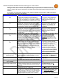
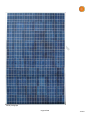
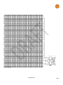
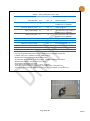
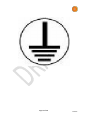
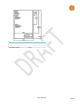
The power from the lower 20% of an idealPV module is independently optimized and added to the power from the upper 80% of the module. In installations where shade is unavoidable, such as row to row shading or roof vent pipes, power loss due to shading will be minimized when the idealPV module is oriented in portrait configuration such that any shadows fall primarily on the lower 20% of the module. Periodic partial shading does not cause cell heating or damage to an idealPV module. Observe all instructions and safety precautions included with the mounting system to be used with the module. Do not install the module near equipment or in location where flammable gases can be generated or collected. Select a proper mounting structure with material thickness of 4 mm (minimum). All mounting hardware must be temperature rated at 90°C (minimum). Do not drill holes in the glass surface of the module. Doing so will void the warranty and could create an electrical hazard. Do not drill additional holes in the module frame. Doing so will void the warranty. Modules must be securely attached to the mounting surface using four mounting holes for normal installation. If heavy wind or snow loads are anticipated, additional mounting points should also be used. Please see the drawing below. The design load for individual module is 30 lb/ft2. Site Load calculations are the responsibility of the system designer or installer. The module must be attached to a support rail using M6 type stainless steel bolt, double washer and nut. Torque 8 N-m. The recommended standoff height is 6 in. The mounting structure and hardware must be made of durable, corrosion, and UV-resistant material. Electrical Installation Grounding All module frames must be properly grounded. Grounding is achieved through secure attachment to the array frame. The array frame shall be grounded in accordance with NEC Article 250. Also observe all local, regional, and national electric codes and regulations. A bonding or toothed washer is required to make proper and reliable electrical grounding connection with the anodized aluminum frame. Devices listed and identified for grounding metallic frames of PV modules are permitted to ground the exposed metallic frames on the module to a grounded mounting structure. Per NEC 250.136, electrical equipment secured to and in electrical contact with a metal rack or structure provided for its support and grounded by one of the means indicated in NEC 250.134 shall be considered effectively grounded. Consider using a GBL4 Solar Module Grounding Lug, rated for outdoor use. The module grounding conductor is to be larger than # 10 AWG. When using a GBL4 Solar Module Grounding Lug, the grounding conductor should be inserted into the opening indicated in the figure, and secured using the set screw. General electrical installation Do not use modules of different configurations in the same system. This module is supplied with Multi Contact connectors for electrical connections. Refer to Section 690.31 of the NEC to determine appropriate types and temperature ratings of conductors. When working with any wiring attached, connected to, or potentially connected to any solar module, all of the solar modules in the circuit should be completely covered with an opaque material to prevent electricity from being generated while connecting or disconnecting conductors. idealPV modules are capable of generating up to their rated ISC and/or VOC in very low light. Always consider the output of any idealPV exposed to any light as an energized high-voltage circuit. Refer to Section 690.8 and 310 of the NEC to determine over-current, conductor capacity, and size requirements. "Rated electrical characteristics are within 10 percent of measured values at Standard Test Conditions of: 1,000 W/m2, 25°C cell temperature and AM 1.5. WARNING Electrical shock hazard! Do not touch bare conductors or other potentially energized parts. Maintenance idealPV recommends the following maintenance items to insure optimum performance of the module: Clean the glass surface of the module as necessary. Use water and a soft sponge or cloth for cleaning. A mild, non-abrasive cleaning agent can be used if necessary. Do not use dishwasher detergent. Electrical and mechanical connections should be checked periodically by qualified personnel to verify that they are clean, secure, and undamaged. Problems should only be investigated by qualified personnel. Follow the manufacturers’ maintenance and inspection schedules for all other components used in the system. Page 3 of 13 130327