1
Manual 07507018
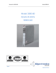
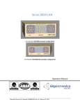
Model 7018
Model 7018
32 SPDT Switch Module
91000150
Manual 07507018
Model 7018
All technical data and specifications in this publication are subject to change without prior notice and do not
represent a commitment on the part of Giga-tronics, Incorporated.
© 2011 Giga-tronics Incorporated. All rights reserved. Printed in the U.S.A.
Warranty
Giga-tronics Series 7000 Switching Modules are warranted against
defective materials and workmanship for three years from date of shipment,
or as detailed in the warranty section of this manual. Giga-tronics will, at its
option, repair or replace products that are proven defective during the
warranty period. This warranty DOES NOT cover damage resulting from
improper use, nor workmanship other than Giga-tronics service. There is no
implied warranty of fitness for a particular purpose, nor is Giga-tronics liable
for any consequential damages. Specification and price change privileges are
reserved by Giga-tronics.
CONTACT INFORMATION
Giga-tronics, Incorporated
4650 Norris Canyon Road
San Ramon, California 94583
Telephone:
800.726.4442 (only within the United States)
925.328.4650
Fax:
925.328.4700
On the Internet:
www.gigatronics.com
Manual 07507018
Model 7018
Regulatory compliance information
This product complies with the essential requirements of the following applicable European Directives,
and carries the CE mark accordingly.
89/336/EEC and 73/23/EEC
EMC Directive and Low Voltage Directive
EN61010-1 (1993)
Electrical Safety
EN61326-1 (1997)
EMC – Emissions and Immunity
Manufacturer’s Name:
Manufacturer’s Address
Giga-tronics, Incorporated
4650 Norris Canyon Road
San Ramon, California 94583
U.S.A.
Type of Equipment:
Model Series Number
Switching Module
7018
Declaration of Conformity on file. Contact Giga-tronics at the following;
Giga-tronics, Incorporated
4650 Norris Canyon Road
San Ramon, California 94583
Telephone:
800.726.4442 (only within the United States)
925.328.4650
Fax:
925.328.4700
Manual 07507018
Model 7018
Record of Changes to This Manual
Use the table below to maintain a permanent record of changes to this document. Corrected
replacement pages are issued as Technical Publication Change Instructions (TPCI). When you are
issued a TPCI, do the following:
1. Insert the TPCI at the front of the manual binder.
2. Remove the pages from the manual binder that are noted in the TPCI.
3. Replace the page(s) removed in the previous step with the corrected page(s).
4. Record the changes in the table below.
TPCI
Number
TPCI Issue
Date
Date Entered
Comments
Manual 07507018
Model 7018
Revision History
Revision
A
B
C
Description of Change
Initial Release 2/02
Updated
Reformatted 5/12
Chg Order #
Approved By
JL
RCW
Manual 07507018
Model 7018
Contents
Contents ....................................................................................................................................................... 6
Chapter 1 Introduction ................................................................................................................................. 7
1.1 Safety and Manual Conventions ........................................................................................................ 7
1.1.1 Product Reference ...................................................................................................................... 7
1.1.2 Personal Safety Alert................................................................................................................... 7
1.1.3 Equipment Safety Alert ............................................................................................................... 7
1.1.4 Notes ........................................................................................................................................... 7
1.1.5 Electrical Safety Precautions ....................................................................................................... 7
Chapter 2 Configuration Table ....................................................................... Error! Bookmark not defined.
Chapter 3 Functional Description ................................................................................................................. 9
3.1 Introduction........................................................................................................................................ 9
3.2 General Description.............................................................................. Error! Bookmark not defined.
Chapter 4 Block Diagram ............................................................................................................................ 10
Chapter 6 Specifications ............................................................................................................................. 11
Chapter 7 Register Map .................................................................................. Error! Bookmark not defined.
Chapter 8 Front Panel Connector Pins ........................................................... Error! Bookmark not defined.
Manual 07507018
Model 7018
Chapter 1 Introduction
1.1 Safety and Manual Conventions
This manual contains conventions regarding safety and equipment usage as described below.
1.1.1 Product Reference
Throughout this manual, the term “Common Core Switching Platform, Series 8800” refers to all models of
within the series, unless otherwise specified.
1.1.2 Personal Safety Alert
WARNING: Indicates a hazardous situation which, if not avoided, could result in death
WARNING
or serious injury.
!
1.1.3 Equipment Safety Alert
CAUTION CAUTION: Indicates a situation which can damage or adversely affect the product or
associated equipment.
1.1.4 Notes
Notes are denoted and used as follows:
NOTE: Highlights or amplifies an essential operating or maintenance procedure, practice, condition or
statement.
1.1.5 Electrical Safety Precautions
Any servicing instructions are for use by service-trained personnel only. To avoid personal injury, do not
perform any service unless you are qualified to do so.
For continued protections against fire hazard, replace the AC line fuse only with a fuse of the same current
rating and type. Do not use repaired fuses or short circuited fuse holders.
Manual 07507018
Model 7018
Chapter 2 Configuration Table
Module
PL91000150
Top Assembly BOM
Assy91000150
Top Assembly
89800740
Font Panel Assembly
PL85003640
PWA BOM
Assy85003640
PWA ASSEMBLY
SCH85003640
PWA SCHEMATIC
Manual 07507018
Model 7018
Chapter 3 Functional Description
3.1 Introduction
This card assembly contains thirty-two SPST (Form A) relays. The card conforms to National Instruments PXI
series specifications and allows ease in design in complex of switching systems.
Manual 07507018
Model 7018
Chapter 4 Block Diagram
Analog Groundplane
Typical Channel (1 of 32). Second Pole
Of DPST grounded for improved Bandwidth.
Manual 07507018
Model 7018
Chapter 6 Specifications
Electrical:
Bandwidth:
Crosstalk:
Max. switching power:
Max. switching current :
Max. switching voltage:
Min. mech. life expectancy:
Initial Contact Resistance:
153 MHz
-22dB @ 100MHz
60 W or 62.5VA
2 Amp
220 VDC or 250 VAC
500K cycles
< 60mΩ
Mechanical:
Size:
Width:
Height:
Length:
Weight:
J1 & J2 connectors:
Mating Connectors:
3U PXI
0.8 inches
5.2 inches
6.5 inches
0.5 lbs.
Positronic, 34 Pos, SMPL34M0TOLB
ASCOR Installation Kit P/N 89800570
Environmental Specifications
Temperature:
Operating:
0º to 55ºC
Storage:
- 40º to 75ºC
Relative Humidity:
Operating:
0 to 90% non-condensing
Storage:
0 to 95% non-condensing
Manual 07507018
Model 7018
Chapter 7 Programming
The Model 7018 is a PXI register based card assembly designed for use with the National Instruments PXI
specification. You can program the Model 7018 in 8, 16 or 32 bit wide data format. By way of your PXI
controller, you can write the data to the appropriate register, shown on the register map, for the relay or
relays in the register that is being closed. When the data bit is true, the relay chosen is closed. You can
determine relay state in a register by simply reading the desired register. Data read back represents the value
of the desired register. In addition, you can read back the coil state to verify that the coil is driven correctly by
the program register. This scenario verifies that the program register has correctly controlled the relay coil.
A register map can be organized to show the relay designation at each register, followed by the register’s
functionality and the path connections to the front panel. PXI automatically assigns the starting address of the
card, called Bar0. Bar0 becomes the starting address of the first register. Each address location controls 8 bits.
The control functions using 16 format are shown in the illustration below.
Programming of the Model 7018 is very straight forward. The module is organized as 32 SPST 1 Amp general
purpose relay board. The location of the first register is assigned by the PCI enumerator. This is designated as
"Bar0" or the starting address of the card. The program registers using 16 bit format are located as follows:
Register #1:
BIT
15
K16
BIT
14
K15
Register #2:
BIT
31
K32
BIT
30
K31
read/write function:
coil read back:
BIT
13
K14
BIT
12
K13
BIT
11
K12
BIT
10
K11
read/write function:
coil read back:
BIT
29
K30
BIT
28
K29
BIT
27
K28
BIT
26
K27
Bar0 + 0000h
Bar0 + 0008h
BIT
9
K10
BIT
8
K09
BIT
7
K08
BIT
6
K07
BIT
5
K06
BIT
4
K05
BIT
3
K04
BIT
2
K03
BIT
1
K02
BIT
0
K01
BIT
22
K23
BIT
21
K22
BIT
20
K21
BIT
19
K20
BIT
18
K19
BIT
17
K18
BIT
16
K17
Bar0 + 0002h
Bar0 + 000Ah
BIT
25
K26
BIT
24
K25
BIT
23
K24
Manual 07507018
Model 7018
Chapter 8 Connector Pin Assignments
J1
FRONT PANEL CONNECTOR
PIN POSITION
AS YOU FACE CONNECTOR
MM
NN
KK
LL
HH
JJ
EE
FF
CC
DD
M
BB
Y
Z
W
X
U
V
S
T
P
R
M
N
K
L
H
J
E
F
C
D
A
B
PIN TO INTERNAL CONNECTION
Pin #
A
B
C
D
E
F
H
J
K
L
M
N
P
R
S
T
U
V
W
X
Y
Z
AA
BB
CC
DD
EE
FF
HH
JJ
KK
LL
MM
NN
Description
Relay #1 in
Relay #1 out
Relay #2 in
Relay #2 out
Relay #3 in
Relay #3 out
Relay #4 in
Relay #4 out
Relay #5 in
Relay #5 out
Relay #6 in
Relay #6 out
Relay #7 in
Relay #7 out
Relay #8 in
Relay #8 out
Relay #9 in
Relay #9 out
Relay #10 in
Relay #10 out
Relay #11 in
Relay #11 out
Relay #12 in
Relay #12 out
Relay #13 in
Relay #13 out
Relay #14 in
Relay #14 out
Relay #15 in
Relay #15 out
Relay #16 in
Relay #16 out
Analog Ground
Analog Ground
User Manual
Model 7018
J2
FRONT PANEL CONNECTOR
PIN POSITION
AS YOU FACE CONNECTOR
MM
NN
KK
LL
HH
JJ
EE
FF
CC
DD
M
BB
Y
Z
W
X
U
V
S
T
P
R
M
N
K
L
H
J
E
F
C
D
A
B
PIN TO INTERNAL CONNECTION
Pin #
A
B
C
D
E
F
H
J
K
L
M
N
P
R
S
T
U
V
W
X
Y
Z
AA
BB
CC
DD
EE
FF
HH
JJ
KK
LL
MM
NN
Description
Relay #17 in
Relay #17 out
Relay #18 in
Relay #18 out
Relay #19 in
Relay #19 out
Relay #20 in
Relay #20 out
Relay #21 in
Relay #21 out
Relay #22 in
Relay #22 out
Relay #23 in
Relay #23 out
Relay #24 in
Relay #24 out
Relay #25 in
Relay #25 out
Relay #26 in
Relay #26 out
Relay #27 in
Relay #27 out
Relay #28 in
Relay #28 out
Relay #29 in
Relay #29 out
Relay #30 in
Relay #30 out
Relay #31 in
Relay #31 out
Relay #32 in
Relay #32 out
Analog Ground
Analog Ground
Page 14
Operation Manual