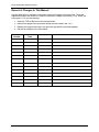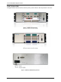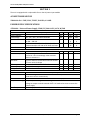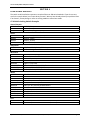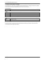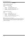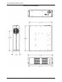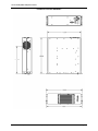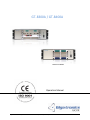
1
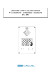
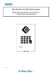
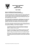
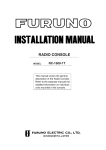
GT-8300A / GT-8400A Model GT-8300A Model GT-8400A Operation Manual Operation Manual, Part Number 07508000-003, Rev. A, Nov. 18, 2010 Series 8300/8400 LAN/GPIB Chassis All technical data and specifications in this publication are subject to change without prior notice and do not represent a commitment on the part of Giga-tronics, Incorporated. © 2010 Giga-tronics Incorporated. All rights reserved. Printed in the U.S.A. Warranty Giga-tronics Series 8300/8400 chassis are warranted against defective materials and workmanship for one (1) year from date of shipment, or as detailed in the warranty section of this manual. Giga-tronics will, at its option, repair or replace products that are proven defective during the warranty period. This warranty DOES NOT cover damage resulting from improper use, nor workmanship other than Giga-tronics service. There is no implied warranty of fitness for a particular purpose, nor is Giga-tronics liable for any consequential damages. Specification and price change privileges are reserved by Giga-tronics. MODEL NUMBERS This Series 8300/8400 chassis includes two models: The eight-slot Model GT-8400A and the four-slot Model GT-8300A. Apart from the number of slots they support, the two models are identical. Both models are referred to in this manual by the general term Series 8300/8400 chassis, except where it is necessary to make a distinction between the models. CONTACT INFORMATION Giga-tronics, Incorporated 4650 Norris Canyon Road San Ramon, California 94583 Telephone: 800.726.4442 (only within the United States) 925.328.4650 Fax: 925.328.4700 On the Internet: www.gigatronics.com Operation Manual, Part Number 07508000-003, Rev. A, Nov. 18, 2010 Page 2 Series 8300/8400 LAN/GPIB Chassis Regulatory compliance information This product complies with the essential requirements of the following applicable European Directives, and carries the CE mark accordingly. 89/336/EEC and 73/23/EEC EMC Directive and Low Voltage Directive EN61010-1 (1993) Electrical Safety EN61326-1 (1997) EMC – Emissions and Immunity Manufacturer’s Name: Manufacturer’s Address Giga-tronics, Incorporated 4650 Norris Canyon Road San Ramon, California 94583 U.S.A. Type of Equipment: Model Series Number: RF/Microwave Switching Sub-System 3U Chassis with LAN, and IEEE-488 Control 8300/8400 Model Numbers: GT-8300A, GT-8400A Declaration of Conformity on file. Contact Giga-tronics at the following; Giga-tronics, Incorporated 4650 Norris Canyon Road San Ramon, California 94583 Telephone: 800.726.4442 (only within the United States) 925.328.4650 Fax: 925.328.4700 Operation Manual, Part Number 07508000-003, Rev. A, Nov. 18, 2010 Page 3 Series 8300/8400 LAN/GPIB Chassis Record of Changes to This Manual Use the table below to maintain a permanent record of changes to this document. Corrected replacement pages are issued as Technical Publication Change Instructions (TCPI). When you are issued a TCPI, do the following: 1. Insert the TCPI at the front of the manual binder. 2. Remove the pages from the manual binder that are noted in the TCPI. 3. Replace the page(s) removed in the previous step with the corrected page(s). 4. Record the changes in the table below. TPCI Number TPCI Issue Date Date Entered Operation Manual, Part Number 07508000-003, Rev. A, Nov. 18, 2010 Comments Page 4 Series 8300/8400 LAN/GPIB Chassis Record of Changes Revision A Description of Change Initial Release Operation Manual, Part Number 07508000-003, Rev. A, Nov. 18, 2010 Chg Order # Approved By 003302 Page 5 Series 8300/8400 LAN/GPIB Chassis Table of Contents SECTION 1 ..................................................................................................................................................... 7 SAFETY AND MANUAL CONVENTIONS...................................................................................................... 7 OVERVIEW................................................................................................................................................. 8 FUNCTIONAL DESCRIPTION....................................................................................................................... 8 WARRANTY ............................................................................................................................................... 8 FRONT/REAR VIEW.................................................................................................................................... 9 SECTION 2 ................................................................................................................................................... 10 UNIT DEFAULTS....................................................................................................................................... 10 SECTION 3 ................................................................................................................................................... 11 AC INPUT MODULE FUSE ........................................................................................................................ 11 52000100-024 - FUSE, 250V, TYPE T, SLO-BLO, 6.3 AMP.................................................................... 11 POWER SUPPLY SPECIFICATIONS ............................................................................................................ 11 47500680 – Universal Power Supply, 250W, 5V/30A & 12V/16.7A, W/FAN ..................................... 11 SECTION 4 ................................................................................................................................................... 12 COMPATIBLE MODULES.......................................................................................................................... 12 GT-8300A Switching Module Examples .............................................................................................. 12 GT-8400A Switching Module Examples .............................................................................................. 13 SECTION 5 ................................................................................................................................................... 14 PARTS LIST/OUTLINE DRAWINGS............................................................................................................ 14 95000110 PARTS LIST (GT-8300A) ...................................................................................................... 14 95000120 PARTS LIST (GT-8400A) ...................................................................................................... 14 95000110 OUTLINE DRAWING............................................................................................................ 15 95000120 OUTLINE DRAWING............................................................................................................ 16 Operation Manual, Part Number 07508000-003, Rev. A, Nov. 18, 2010 Page 6 Series 8300/8400 LAN/GPIB Chassis SECTION 1 SAFETY AND MANUAL CONVENTIONS This manual contains conventions regarding safety and equipment usage as described below. Product Reference Throughout this manual, the term “Series 8300/8400” refers to all models of within the series, unless otherwise specified. Personal Safety Alert ! WARNING WARNING: Indicates a hazardous situation which, if not avoided, could result in death or serious injury. Equipment Safety Alert CAUTION CAUTION: Indicates a situation which can damage or adversely affect the product or associated equipment. Notes Notes are denoted and used as follows: NOTE: Highlights or amplifies an essential operating or maintenance procedure, practice, condition or statement. Electrical Safety Precautions Any servicing instructions are for use by service-trained personnel only. To avoid personal injury, do not perform any service unless you are qualified to do so. For continued protections against fire hazard, replace the AC line fuse only with a fuse of the same current rating and type. Do not use repaired fuses or short circuited fuse holders. Operation Manual, Part Number 07508000-003, Rev. A, Nov. 18, 2010 Page 7 Series 8300/8400 LAN/GPIB Chassis OVERVIEW This manual describes a version of the Series 8300/8400 LAN/GPIB chassis products. Part Numbers (P/N) 95000110A (GT-8300A) and 95000120A (GT-8400A) are both 3U switching system chassis units, with either four (4) slots for installing compatible Giga-tronics ASCOR 3000 series switch modules, or eight (8) slots for installing compatible Giga-tronics ASCOR 4000 series switch modules. Please contact Giga-tronics for a complete list of compatible modules. The Series 8300/8400 chassis units offer Ethernet LAN and GPIB (IEEE-488) communication interfaces, along with a built-in Resource Manager. With high bandwidth available, this allows the creation of large switching systems without the need for external cabling that may have poor impedance control, and have widely varying lengths. The result is a switching solution with the ultimate signal integrity. FUNCTIONAL DESCRIPTION The Series 8300/8400 chassis units are 3U high (5.25 inches), and come with mounting brackets so they may be mounted to fit in a standard 19 inch rack cabinet. Optional rubber feet can also be used to mount these units on a bench top. The units are self contained. That is, they contain their own power supply, Ethernet LAN interface, and GPIB interface. Built-in Resource Manager The Series 8300/8400 uses Giga-tronics / ASCOR family of switch modules. The 8300 uses the Series 3000 switch cards and the 8400 uses the Series 4000 switch cards. These switch modules use the VXI platform. The 8300/8400 chassis has the VXI slot 0 controller built-in and provides the resource management to control the modules that are plugged into the chassis. A Plug-n-Play driver used for a VXI platform will work with these chassis'. The advantage is those customers who are using our switch modules in VXI can migrate to the Series 8300/8400 and their programs will still work without modification. This eliminates the need for a separate slot 0 controller. A single power supply supplies +5.0 Volts DC and +12.0 Volts DC to the unit. The power supply input is 90-250 Volts AC, 47-63 Hz. (See Section 3 for full specifications) WARRANTY Product is warranted to conform to all applicable specifications for a period of one (1) year from the date of shipping. Operation Manual, Part Number 07508000-003, Rev. A, Nov. 18, 2010 Page 8 Series 8300/8400 LAN/GPIB Chassis FRONT/REAR VIEW The figures below illustrate the front and rear power, power indicator and slot positions for the units. Figure 1 – 95000110 Front panel view (shown with optional modules installed) Figure 2 – 95000120 Front panel view (shown with optional modules installed) Figure 3 – 95000110 / 95000120 Rear panel view Operation Manual, Part Number 07508000-003, Rev. A, Nov. 18, 2010 Page 9 Series 8300/8400 LAN/GPIB Chassis SECTION 2 UNIT DEFAULTS This unit is shipped from the factor with the following default settings: Default IP Address: 192.168.0.254 Default Timeout: 120 seconds NOTE: Any software details referred to in this manual assume that the device is properly connected to the communications interface and this interface is functional. CAUTION Please consult Giga-tronics factory before making any changes in your equipment! Operation Manual, Part Number 07508000-003, Rev. A, Nov. 18, 2010 Page 10 Series 8300/8400 LAN/GPIB Chassis SECTION 3 The unit is equipped with a replaceable fuse on the AC power input module AC INPUT MODULE FUSE 52000100-024 - FUSE, 250V, TYPE T, SLO-BLO, 6.3 AMP POWER SUPPLY SPECIFICATIONS 47500680 – Universal Power Supply, 250W, 5V/30A & 12V/16.7A, W/FAN INPUT Parameter Conditions /Description Min Nom Max Units Input Frequency 47 63 Hz Input Voltage 90 – 132 / 180 – 264 Auto-selectable 90 264 VAC Input Current At 100 – 120 VAC 8 A At 200 – 240 VAC 4 A Inrush Current Peak measured at 230 VAC at full load, cold start 70 A Peak measured at 115 VAC at full load, cold start 35 A Power Factor Passive power factor correction meets EN61000-3-2 class a OUTPUT Parameter Conditions /Description Min Nom Max Units Transient Response Output voltage returns to within 1 % in less than 2.5 ms for a 50 % load change. Peak transient does not exceed 5 % Overshoot Turn-on and turn-off overshoot shall not exceed 5% over nominal voltage Efficiency Measured at 230 VAC and full load 75 % Turn on Delay At 120 VAC 1 second Hold up Time At 120 VAC and 80 % of rated maximum load 20 ms PROTECTION CIRCUIT Parameter Conditions /Description Overload Current limiting starts at 110 – 140 % of the rated output current in foldback mode and recovers automatically Short Circuit Short circuit can be continuous. Recovers automatically upon removal of shout Output Over-voltage Output is protected against over-voltage. Unit shuts down and latches when the voltage at output terminals exceeds 130 %. AC needs to be reset to restart the power supply Over Temperature Power Supply shuts down when temperature is in excess of 85°C. Auto Recovery Operation Manual, Part Number 07508000-003, Rev. A, Nov. 18, 2010 Page 11 Series 8300/8400 LAN/GPIB Chassis SECTION 4 COMPATIBLE MODULES The switch cards listed below represent a sample of the over 200 switch modules. If you do not see a card in the sample below, let us know what you need - We may have already solved your problem! Even if we haven’t, we may design or tailor an existing module to meet those needs. GT-8300A Switching Module Examples General Purpose 3000-12 3000-53 3000-60 32 SPDT, 2 Amp 96 SPDT, 2 Amp 2 DPDT, 2 Amp High Frequency Power 3000-02 3000-42 3000-43 3000-51 96 General Purpose SPST, 5 Amp 48 SPDT, 5 Amp 48 SPST, 10 Amp 20 SPDT, 20 Amp Relay Driver 3000-04 3000-48 128 Channel Relay Driver, 500 mA 16 Channel High Power Driver with Timer Microwave 3000-80 3000-226 3000-236T 3000-246 3000-286 3000-23236T 3000-24662 3000-26662T Six 6 x 1, 26.5 GHz, Single Slot Two 6 x 1, 26.5 GHz Three 6 x 1, 18 GHz, Terminated Four 6 x 1, 26.5 GHz Eight 6 x 1, 26.5 GHz Three 2 x 1, Three 6 x 1, 18 GHz, Terminated Four 6 x 1 and Six SPDT 26.5 GHz Six 6 x 1, Six 2 x 1, 18 GHz, Terminated Matrix 3000-05 3000-06 3000-44 3000-44-opt1 3000-45 3000-45B 3000-47 3000-47-opt1 3000-52 3000-52-opt1 3000-57 36 x 2 Coaxial Matrix Dual 18 x 2 Coaxial Matrix 128 x 2, 2-wire Coaxially Shielded Matrix Dual 64 x 2, 2-wire Coaxially Shielded Matrix 64 x 4, 2-wire Coaxially Shielded Matrix 128 x 4, 2-wire Coaxially Shielded Matrix 32 x 8, 2-wire Shielded Matrix Dual 16 x 8, 2-wire Shielded Matrix 32 x 8, 2-wire Matrix Dual 16 x 8, 2-wire Matrix 64 x 4, 2-wire Matrix Tree 3000-03 3000-08 Quad 30 x 1, Trees with Switched Guards, Coaxially Shielded Quad 60 x 1, Trees with Switched Guards, Coaxially Shielded Operation Manual, Part Number 07508000-003, Rev. A, Nov. 18, 2010 Page 12 Series 8300/8400 LAN/GPIB Chassis GT-8400A Switching Module Examples Series 4000 switch cards use slim, high density switch boards with 0.5” spacing. This allows for medium to high density switching configurations in the minimum physical space. General Purpose 4096 96 SPST Matrix 4513 4524 4525 4526 8 x 8 Single-Wire Matrix with (8) 4-Pole Star Switch 16 x 8 Matrix 48 x 16 Matrix HF Coax MUX with Virginia Panel Connectors Tree 4108 45152 Twelve 8 x 1, Tree Eight 6 x 1, 2-wire Tree Normal installation procedures should be followed with installing any modules. Please refer to the instructions that come with each module. Operation Manual, Part Number 07508000-003, Rev. A, Nov. 18, 2010 Page 13 Series 8300/8400 LAN/GPIB Chassis SECTION 5 PARTS LIST/OUTLINE DRAWINGS 95000110 PARTS LIST (GT-8300A) 95000110 85007340 47000590 47500680 52000100-024 Top Level Assembly PCA, 8300 BACKPLANE 4 WIDE 1.2 – Rev. B PCA, LAN/GPIB CONTROLLER, SCPMII Power Supply, 5VDC/30A & 12VDC/16.7A with Fan Fuse, 250V, Type T, SLO-BLO, 6.3 Amp 95000120 PARTS LIST (GT-8400A) 95000120 85007360 47000590 47500680 52000100-024 Top Level Assembly 8400 BACKPLANE 8 X .6, PCA – Rev. B PCA, LAN/GPIB CONTROLLER, SCPMII Power Supply, 5VDC/30A & 12VDC/16.7A with Fan Fuse, 250V, Type T, SLO-BLO, 6.3 Amp NOTE: Only the major components are listed above. The functional difference between models 95000110 (GT-8300A) and 95000120 (GT-8400A) is the number of slots in the backplane, and the form factor of the modules that can be used in each chassis. The 3000 series modules are compatible with the GT-8300A while the 4000 series modules are compatible with the GT-8400A. Operation Manual, Part Number 07508000-003, Rev. A, Nov. 18, 2010 Page 14 Series 8300/8400 LAN/GPIB Chassis 95000110 OUTLINE DRAWING Operation Manual, Part Number 07508000-003, Rev. A, Nov. 18, 2010 Page 15 Series 8300/8400 LAN/GPIB Chassis 95000120 OUTLINE DRAWING Operation Manual, Part Number 07508000-003, Rev. A, Nov. 18, 2010 Page 16 Series 8300/8400 LAN/GPIB Chassis Notes Operation Manual, Part Number 07508000-003, Rev. A, Nov. 18, 2010 Page 17 Series 8300/8400 LAN/GPIB Chassis This page intentionally left blank Operation Manual, Part Number 07508000-003, Rev. A, Nov. 18, 2010 Page 18