1
12
2 Setup and settings
2.1 Introduction
8
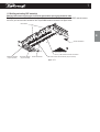
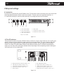
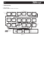
The figure below shows the front panel of DIGAM L Series. The front panel controls and indicators give to the user the total
control and detailed information about the status of the amplifier. The gain control use a logarithmic scale from to +32dB. Read carefully the instructions below that help you to manage the functions of the amplifier.
CLIP
CLIP
-6dB
-6dB
-18dB
-18dB
SIGNAL
SIGNAL
TEMP
READY
A
F B
READY
C G
R
I
O
TEMP
D
E
A - Gain control channel 1
B - Gain control channel 2
C - Gain control channel 3*
D - Gain control channel 4*
E - Power switch
F - LED indicators channel 1 and 2
G - LED indicators channel 3 and 4*
* only for "LQ" models
figure 2.1.1
2.2 The LED indicators
The figure below shows the front panel of DIGAM L Series. and refers to a single couple of channels. The clip LED, when
lighting, indicates the clipping state for the output stage of the correspondig channel. The signal, -18dB and -6dB LEDs
operate as V-meter and the signal LED is lighted when the signal is present in the input stage of the correspondent
channel. The "ready" LED, when lighted, indicates that the startup time after power-on is finished and the amplifier is
ready to use. The "temp" LED, when lighted, indicates that the output stage of the corresponding channel is reducing the
output power due to an over-heated state.
CLIP
-6dB
-18dB
SIGNAL
TEMP
READY
A B C D E
A - Clipping and protection indicator channel 1 (or 3)
B - -6dB output level indicator channel 1 (or 3)
C - -18dB output level indicator channel 1 (or 3)
D - signal presence indicator channel 1 (or 3)
E - "Ready" indicator
F G H I J
F - Over-temperature indicator
G - Signal presence indicator channel 2 (or 4)
H - -18dB output level indicator channel 2 (or 4)
I - -6dB output level indicator channel 2 (or 4)
J - Clipping and protection indicator channel 2 (or 4)
figure 2.1.2