1
User Manual
Combination Generator Control Module
Catalog Numbers 1407-CGCM
Important User Information
Read this document and the documents listed in the additional resources section about installation, configuration, and
operation of this equipment before you install, configure, operate, or maintain this product. Users are required to
familiarize themselves with installation and wiring instructions in addition to requirements of all applicable codes, laws,
and standards.
Activities including installation, adjustments, putting into service, use, assembly, disassembly, and maintenance are required
to be carried out by suitably trained personnel in accordance with applicable code of practice.
If this equipment is used in a manner not specified by the manufacturer, the protection provided by the equipment may be
impaired.
In no event will Rockwell Automation, Inc. be responsible or liable for indirect or consequential damages resulting from the
use or application of this equipment.
The examples and diagrams in this manual are included solely for illustrative purposes. Because of the many variables and
requirements associated with any particular installation, Rockwell Automation, Inc. cannot assume responsibility or
liability for actual use based on the examples and diagrams.
No patent liability is assumed by Rockwell Automation, Inc. with respect to use of information, circuits, equipment, or
software described in this manual.
Reproduction of the contents of this manual, in whole or in part, without written permission of Rockwell Automation,
Inc., is prohibited.
Throughout this manual, when necessary, we use notes to make you aware of safety considerations.
WARNING: Identifies information about practices or circumstances that can cause an explosion in a hazardous environment,
which may lead to personal injury or death, property damage, or economic loss.
ATTENTION: Identifies information about practices or circumstances that can lead to personal injury or death, property
damage, or economic loss. Attentions help you identify a hazard, avoid a hazard, and recognize the consequence.
IMPORTANT
Identifies information that is critical for successful application and understanding of the product.
Labels may also be on or inside the equipment to provide specific precautions.
SHOCK HAZARD: Labels may be on or inside the equipment, for example, a drive or motor, to alert people that dangerous
voltage may be present.
BURN HAZARD: Labels may be on or inside the equipment, for example, a drive or motor, to alert people that surfaces may
reach dangerous temperatures.
ARC FLASH HAZARD: Labels may be on or inside the equipment, for example, a motor control center, to alert people to
potential Arc Flash. Arc Flash will cause severe injury or death. Wear proper Personal Protective Equipment (PPE). Follow ALL
Regulatory requirements for safe work practices and for Personal Protective Equipment (PPE).
Allen-Bradley, Rockwell Software, Rockwell Automation, ControlLogix, Logix5000, and RSLogix are trademarks of Rockwell Automation, Inc.
Trademarks not belonging to Rockwell Automation are property of their respective companies.
3UMMARYOF#HANGES
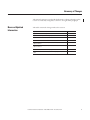
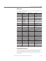
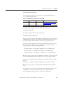
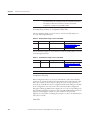
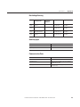
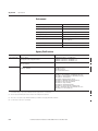
This manual contains new and updated information. Changes throughout this
revision are marked by change bars, as shown to the right of this paragraph.
.EWAND5PDATED
)NFORMATION
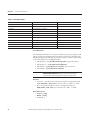
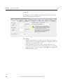
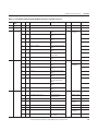
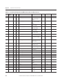
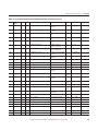
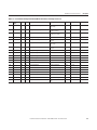
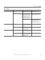
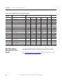
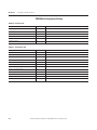
This table contains the changes made to this revision.
4OPIC
0AGE
Updated the dimension diagrams
14
Updated the Configuration Messaging section
129
Added information for the Network status indicator
164
Added information for the Module status indicator
165
Updated the Get Attributes All (service code 0x01) table for Identity
Object Instance 1
198
Updated the Get Attributes All (service code 0x01) table for Identity
Object Instance 2
199
Added a Device Status for Identity Object Instance 2
199
Updated the Certification information in the Agency Certifications
table
210
Rockwell Automation Publication 1407-UM001H-EN-P - November 2014
3UMMARYOF#HANGES
.OTES
Rockwell Automation Publication 1407-UM001H-EN-P - November 2014
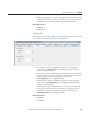
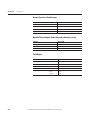
4ABLEOF#ONTENTS
0REFACE
Additional Resources . . . . . . . . . . . . . . . . . . . . . . . . . . . . . . . . . . . . . . . . . . . . . . 7
#HAPTER
'ENERAL)NFORMATION
Introduction . . . . . . . . . . . . . . . . . . . . . . . . . . . . . . . . . . . . . . . . . . . . . . . . . . . . . 9
Functions . . . . . . . . . . . . . . . . . . . . . . . . . . . . . . . . . . . . . . . . . . . . . . . . . . . . . . . . 9
#HAPTER
)NSTALLATION
Mounting Requirements . . . . . . . . . . . . . . . . . . . . . . . . . . . . . . . . . . . . . . . . . . 13
Electrical Connections. . . . . . . . . . . . . . . . . . . . . . . . . . . . . . . . . . . . . . . . . . . . 15
#HAPTER
#'#-5NIT/PERATION
Inputs and Outputs . . . . . . . . . . . . . . . . . . . . . . . . . . . . . . . . . . . . . . . . . . . . . . 38
Communication . . . . . . . . . . . . . . . . . . . . . . . . . . . . . . . . . . . . . . . . . . . . . . . . . 42
Operational Functions. . . . . . . . . . . . . . . . . . . . . . . . . . . . . . . . . . . . . . . . . . . . 43
#HAPTER
#'#-5NIT#ONFIGURATION
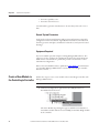
Introduction . . . . . . . . . . . . . . . . . . . . . . . . . . . . . . . . . . . . . . . . . . . . . . . . . . . .
Overview of the Configuration Process. . . . . . . . . . . . . . . . . . . . . . . . . . . . .
Preparation . . . . . . . . . . . . . . . . . . . . . . . . . . . . . . . . . . . . . . . . . . . . . . . . . . . . . .
Create a New Module in the ControlLogix Controller . . . . . . . . . . . . . .
Device Setup . . . . . . . . . . . . . . . . . . . . . . . . . . . . . . . . . . . . . . . . . . . . . . . . . . . . .
71
71
71
72
75
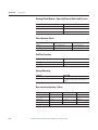
#HAPTER
#'#-5NIT3TARTUP
Introduction . . . . . . . . . . . . . . . . . . . . . . . . . . . . . . . . . . . . . . . . . . . . . . . . . . . .
Safety . . . . . . . . . . . . . . . . . . . . . . . . . . . . . . . . . . . . . . . . . . . . . . . . . . . . . . . . . .
Recommended Equipment . . . . . . . . . . . . . . . . . . . . . . . . . . . . . . . . . . . . . . .
Recommended Start-up Procedure. . . . . . . . . . . . . . . . . . . . . . . . . . . . . . . .
Document Configuration Parameter and Wiring Changes . . . . . . . . . .
107
107
108
109
125
#HAPTER
#'#-5NIT3OFTWARE)NTERFACE
Introduction . . . . . . . . . . . . . . . . . . . . . . . . . . . . . . . . . . . . . . . . . . . . . . . . . . . . 127
CGCM Unit User Program Interface . . . . . . . . . . . . . . . . . . . . . . . . . . . . . 128
CGCM Unit Data Tables. . . . . . . . . . . . . . . . . . . . . . . . . . . . . . . . . . . . . . . . 132
#HAPTER
4ROUBLESHOOTING
. . . . . . . . . . . . . . . . . . . . . . . . . . . . . . . . . . . . . . . . . . . . . . . . . . . . . . . . . . . . . . . . 153
!PPENDIX!
4IME/VERCURRENT
#HARACTERISTIC#URVES
General. . . . . . . . . . . . . . . . . . . . . . . . . . . . . . . . . . . . . . . . . . . . . . . . . . . . . . . . . 169
Curve Specifications . . . . . . . . . . . . . . . . . . . . . . . . . . . . . . . . . . . . . . . . . . . . . 169
Time Over-current Characteristic Curve Graphs. . . . . . . . . . . . . . . . . . . 170
Rockwell Automation Publication 1407-UM001H-EN-P - November 2014
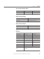
4ABLEOF#ONTENTS
!PPENDIX"
#'#-5NIT-ATH-ODELS
Introduction . . . . . . . . . . . . . . . . . . . . . . . . . . . . . . . . . . . . . . . . . . . . . . . . . . . .
Synchronous Machine Terminal Voltage Transducer and Load
Compensator Model. . . . . . . . . . . . . . . . . . . . . . . . . . . . . . . . . . . . . . . . . . . . .
Voltage Regulator . . . . . . . . . . . . . . . . . . . . . . . . . . . . . . . . . . . . . . . . . . . . . . .
VAR/Power Factor Controller . . . . . . . . . . . . . . . . . . . . . . . . . . . . . . . . . . .
Limiters . . . . . . . . . . . . . . . . . . . . . . . . . . . . . . . . . . . . . . . . . . . . . . . . . . . . . . . .
V/Hz Limiter . . . . . . . . . . . . . . . . . . . . . . . . . . . . . . . . . . . . . . . . . . . . . . . . . . .
Soft Start Control . . . . . . . . . . . . . . . . . . . . . . . . . . . . . . . . . . . . . . . . . . . . . . .
Field Current Regulator . . . . . . . . . . . . . . . . . . . . . . . . . . . . . . . . . . . . . . . . .
189
189
190
191
191
193
194
195
!PPENDIX#
!DDITIONAL#ONTROL.ET.ETWORK ControlNet Application Objects . . . . . . . . . . . . . . . . . . . . . . . . . . . . . . . . . 197
)NFORMATION
!PPENDIX$
. . . . . . . . . . . . . . . . . . . . . . . . . . . . . . . . . . . . . . . . . . . . . . . . . . . . . . . . . . . . . . . . 201
3PECIFICATIONS
!PPENDIX%
$ETAILED#'#-5NIT4AG
$ESCRIPTIONS
Generator Parameters and Configuration Status . . . . . . . . . . . . . . . . . . .
General Excitation Control Modes . . . . . . . . . . . . . . . . . . . . . . . . . . . . . . .
AVR Mode . . . . . . . . . . . . . . . . . . . . . . . . . . . . . . . . . . . . . . . . . . . . . . . . . . . . .
FCR Mode . . . . . . . . . . . . . . . . . . . . . . . . . . . . . . . . . . . . . . . . . . . . . . . . . . . . .
Power Factor Mode. . . . . . . . . . . . . . . . . . . . . . . . . . . . . . . . . . . . . . . . . . . . . .
VAR Mode . . . . . . . . . . . . . . . . . . . . . . . . . . . . . . . . . . . . . . . . . . . . . . . . . . . . .
Excitation Control Features . . . . . . . . . . . . . . . . . . . . . . . . . . . . . . . . . . . . . .
Protection . . . . . . . . . . . . . . . . . . . . . . . . . . . . . . . . . . . . . . . . . . . . . . . . . . . . . .
Synchronizing. . . . . . . . . . . . . . . . . . . . . . . . . . . . . . . . . . . . . . . . . . . . . . . . . . .
Load Sharing. . . . . . . . . . . . . . . . . . . . . . . . . . . . . . . . . . . . . . . . . . . . . . . . . . . .
Metering . . . . . . . . . . . . . . . . . . . . . . . . . . . . . . . . . . . . . . . . . . . . . . . . . . . . . . .
Redundancy . . . . . . . . . . . . . . . . . . . . . . . . . . . . . . . . . . . . . . . . . . . . . . . . . . . .
213
214
215
216
217
218
219
222
228
231
233
235
!PPENDIX&
#ONFIGURATION2ECORD
7ORKSHEET
Generator Information . . . . . . . . . . . . . . . . . . . . . . . . . . . . . . . . . . . . . . . . . . 237
)NDEX
. . . . . . . . . . . . . . . . . . . . . . . . . . . . . . . . . . . . . . . . . . . . . . . . . . . . . . . . . . . . . . . . 245
Rockwell Automation Publication 1407-UM001H-EN-P - November 2014
0REFACE
The information in this manual applies to the 1407-CGCM module, Series D,
Revision A, with host firmware revision 4.25 and ControlNet firmware
revision 1.07. The manual notes differences with earlier versions of the product
where they occur.
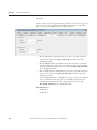
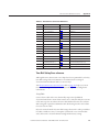
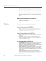
!DDITIONAL2ESOURCES
These documents contain additional information concerning related products
from Rockwell Automation.
2ESOURCE
$ESCRIPTION
Safety Guidelines for the Application,
Installation and Maintenance of Solid State
Controls, publication SGI-1.1
Describes some important differences between
solid-state equipment and hard-wired
electromechanical devices.
ControlNet Coax Media Planning and
Installation, publication CNET-IN002
Provides installation procedures for the
ControlNet network.
Logix5000™ Controllers Common Procedures,
publication 1756-PM001
Provides information about RSLogix™ 5000
software.
CGCM Release Notes, publication 1407-RN001
Provides information on compatible RSLogix
5000 software versions and ControlLogix®
controller firmware revisions.
Industrial Automation Wiring and Grounding
Guidelines, publication 1770.4.1.
Provides general guidelines for installing a
Rockwell Automation industrial system.
Product Certifications website,
http://www.ab.com
Provides declarations of conformity, certificates,
and other certification details.
You can view or download publications at http://www.rockwellautomation.com/
literature/. To order paper copies of technical documentation, contact your local
Allen-Bradley distributor or Rockwell Automation sales representative.
Rockwell Automation Publication 1407-UM001H-EN-P - November 2014
0REFACE
.OTES
Rockwell Automation Publication 1407-UM001H-EN-P - November 2014
#HAPTER
'ENERAL)NFORMATION
)NTRODUCTION
The Combination Generator Control Module (CGCM unit) is a
microprocessor-based control and protection device. The CGCM unit is
designed to integrate with a Logix family programmable controller to provide
generator control, protection and synchronization functions. Programmability of
system parameters, regulation settings, and protective functions enable the
CGCM unit to be used in a wide range of applications.
&UNCTIONS
The following sections outline the functions of the unit.
'ENERATOR2EGULATIONAND#ONTROL&UNCTIONS
This list contains the generator regulation and control functions:
• Four excitation control modes
• Automatic voltage regulation (AVR)
• Manual or field current regulation (FCR)
• Power factor (PF)
• Reactive power (VAR)
• Soft start voltage buildup with an adjustable ramp in AVR and FCR
control modes
• Over-excitation (OEL) and under-excitation (UEL) limiting in AVR,
VAR, and PF control modes
• Under-frequency compensation (Volts/Hertz)
• Line drop compensation
• Auto-tracking between operating modes and between redundant CGCM
units
• Automatic transfer to a back-up CGCM unit in redundant systems
• Generator paralleling with reactive droop compensation or cross-current
(reactive differential) compensation
• Generator paralleling with real power load sharing
• Synchronizing for one or two circuit breakers
Rockwell Automation Publication 1407-UM001H-EN-P - November 2014
#HAPTER
General Information
'ENERATOR0ROTECTION&UNCTIONS
This list contains the generator protection functions:
• Loss of excitation current (40)
• Over-excitation voltage (59F)
• Generator over-voltage (59)
• Generator under-voltage (27)
• Loss of sensing (60FL)
• Loss of permanent magnet generator
(PMG/Excitation power) (27)
• Reverse VAR (40Q)
• Over-frequency (81O)
• Under-frequency (81U)
• Reverse power (32R)
• Rotating diode monitor
• Phase rotation error (47)
• Generator over-current (51)
-ETERING&UNCTIONS
This list contains the metering functions:
• Voltage
• Current
• Frequency
• Real Power
• Apparent Power
• Reactive Power
• Power Factor
• Real Energy (kWh)
• Apparent Energy (kVAh)
• Reactive Energy (kVARh)
• Controller Excitation Current and Voltage
• Diode Monitor Ripple Level
• Load Share Error
• Synchronization Parameters
Rockwell Automation Publication 1407-UM001H-EN-P - November 2014
General Information
#HAPTER )NPUTS
This list contains the inputs for the CGCM unit:
• Single-phase or 3-phase true rms generator voltage sensing
• Single-phase dual bus or 3-phase single bus voltage sensing
• 3-phase generator current sensing (1 or 5 A nominal)
• Single-phase cross current loop 1 or 5 A current transformer (CT) input
• Auxiliary ±10V DC input providing remote control of the setpoints
• DC power input
/UTPUTS
This list contains the outputs for the CGCM unit:
• Pulse-width modulated output power stage rated at 15 A
• Discrete redundancy relay output
• Discrete fault output driver
• Load sharing connection for use with the Allen-Bradley Line
Synchronization Module (1402-LSM) or compatible hardware
#OMMUNICATION)NTERFACES
The CGCM unit has these three communication ports:
• Redundant ControlNet connector
• RS-232 port for dedicated communication with a redundant CGCM
• RS-232 port for factory configuration and test (not for customer use)
Rockwell Automation Publication 1407-UM001H-EN-P - November 2014
#HAPTER
General Information
.OTES
Rockwell Automation Publication 1407-UM001H-EN-P - November 2014
#HAPTER
)NSTALLATION
-OUNTING2EQUIREMENTS
This equipment is intended for use in a Pollution Degree 2 Industrial
Environment, in over-voltage Category II applications (as defined by IEC
publication 60664-1). Because the units contain a heat sink, they must be
mounted vertically. Any other mounting angle reduces the heat dissipation
capabilities of the units, possibly leading to premature failure of critical
components. The unit can be mounted anywhere that the ambient temperature
does not exceed the rated environmental conditions or clearance requirements.
The clearance requirements for the CGCM unit are:
• 63.5 mm (2.5 in.) of clearance is required on both sides of the unit when
mounted.
• 101.6 mm (4 in.) of clearance is required above and below the unit when
mounted.
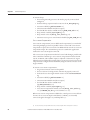
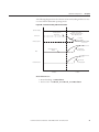
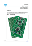
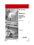
Overall dimensions for the unit are shown in CGCM Unit Overall Dimensions
on page 14.
7!2.).'Explosion Hazard
s Substitution of components can impair suitability for Class I, Division 2.
s Do not replace components or disconnect equipment unless power has been switched
off or the area is known to be non-hazardous.
s Do not connect or disconnect components unless power has been switched off or the
area is known to be non-hazardous.
s This product must be installed in an enclosure. All cables connected to the product
must remain in the enclosure or be protected by conduit or other means.
s All wiring must comply with N.E.C. article 501-4(b).
Rockwell Automation Publication 1407-UM001H-EN-P - November 2014
#HAPTER
Installation
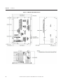
&IGURE#'#-5NIT/VERALL$IMENSIONS
Rockwell Automation Publication 1407-UM001H-EN-P - November 2014
Installation
%LECTRICAL#ONNECTIONS
#HAPTER The CGCM unit’s connections are dependent on the application and excitation
scheme. All inputs or outputs cannot be used in a given installation. Incorrect
wiring can result in damage to the unit.
Connect the CGCM unit’s terminals with copper wire rated for a minimum of
600V. General appliance wire rated for minimum temperatures of 105 °C
(221 °F) is acceptable. All wire must be copper. Select circuit conductors based on
good design practice.
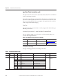
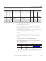
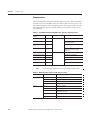
The wire gauge range listed in the Terminal Block Label Description table
indicates the physical capabilities of the connector.
The CGCM unit’s terminals are on the front, bottom, and right panel of the unit.
The nine-pin connector on the bottom of the unit is used for communication
between CGCM units in a redundant system. Suggested torque for terminal
screws is 1 N•m (9 lb•in).
Refer to pages 17…34 for typical connection diagrams.
Terminals to be used as landing points for shielded wires are provided on several
terminal strips. Shield terminals with the same name are internally connected
together but are not connected to protective earth or any internal unit circuitry.
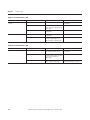
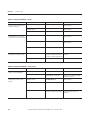
4ABLE4ERMINAL"LOCK,ABEL$ESCRIPTION
4ERMINAL"LOCK
7IRE'AUGE
2ANGE
,ABEL
$ESCRIPTION
TB1
2.6…2.1 mm2
(10…12 AWG)
PMG A
Phase A excitation power supply
PMG B
Phase B excitation power supply (three phase only)
PMG C
Phase C excitation power supply
SHLD1
Shield 1 landing points are tied together but are not connected internally to protective earth or
other unit circuitry
SHLD1
TB2
SHLD2
SHLD2
Shield 2 landing points are tied together but are not connected internally to protective earth or
other unit circuitry
EXC(-)
Excitation output negative
EXC(+)
Excitation output positive
Rockwell Automation Publication 1407-UM001H-EN-P - November 2014
#HAPTER
Installation
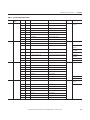
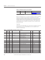
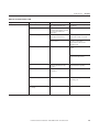
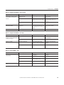
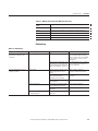
4ABLE4ERMINAL"LOCK,ABEL$ESCRIPTION
4ERMINAL"LOCK
7IRE'AUGE
2ANGE
,ABEL
$ESCRIPTION
TB3
2.6…2.1 mm2
(10…12 AWG)
ID(+)1 A
1 A cross-current compensation CT input
ID(+)5 A
5 A cross-current compensation CT input
TB4
Cross-current compensation CT common input
I3(+)1 A
1 A phase C CT input
I3(+)5 A
5 A phase C CT input
I3(-)
Phase C CT common input
I2(+)1 A
1 A phase B CT input
I2(+)5 A
5 A phase B CT input
I2(-)
Phase B CT common input
I1(+)1 A
1 A phase A CT input
I1(+)5 A
1 A phase A CT input
I1(-)
Phase A CT common input
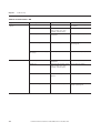
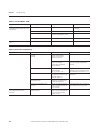
1.6…1.0 mm2
BAT(+)
24V DC control power input
(14…18 AWG)
BAT(-)
24V DC control power return
FLT
Open collector fault output
RD RLY
Open collector output for redundancy relay
CH GND
Chassis ground
V Gen A
Phase A generator voltage input
V Gen B
Phase B generator voltage input
V Gen C
Phase C generator voltage input
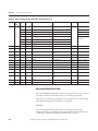
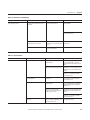
TB5
TB6
TB7
ID(-)
1.6…1.0 mm2
(14…18 AWG)
V Gen N
Neutral generator voltage input
V Bus A
Phase A bus voltage input(1)
V Bus B
Phase B bus voltage input(1)
V Bus C
Phase C bus voltage input
V Bus N
Neutral bus voltage input
VREF(+)
Remote setpoint adjust input
VREF(-)
Remote setpoint adjust input return
SHLD3
Shield 3 landing points are tied together but are not connected internally to protective earth or
other unit circuitry
SHLD3
A-COM
Analog common
EX-D(+)
Excitation enable input
EX-D(-)
Excitation enable return
LS(+)
Real power load sharing input
LS(-)
Real power load sharing return
SHLD4
Shield 4 landing point is not connected internally to protective earth or other unit circuitry
(1) When used in a dual breaker configuration, Bus A voltage input is wired from V Bus A to V Bus N and Bus B is wired from V Bus B to V Bus N.
Rockwell Automation Publication 1407-UM001H-EN-P - November 2014
Installation
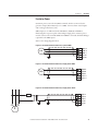
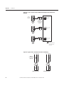
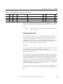
#HAPTER %XCITATION0OWER
Excitation power is wired to the PMG terminals, whether connected to the
generator output (Shunt Excited) or to a PMG. Connect shunt excited inputs
with a voltage transformer (VT).
PMG inputs are on TB1 and are labeled PMG A, PMG B, and PMG C,
illustrating their respective phase relationships. Single-phase excitation power
must be connected to terminals PMG A and PMG C. Twisted, shielded cabling is
required for the PMG inputs.
Refer to the wiring diagrams below.
&IGURE%XCITATION0OWER#ONNECTIONSPHASE0-'
0- '!
0-' "
0-'#
3(, $ 3(, $ 0-'
4"
&IGURE%XCITATION0OWER#ONNECTIONS3INGLEPHASE0-'
0-'!
0-'"
0- '#
3(,$ 3(,$ 0-'
4"
&IGURE%XCITATION0OWER#ONNECTIONS3INGLEPHASE3HUNT
&USE
"
!
0-'!
0-'"
0- '#
3(,$ 3(,$ #
4"
'
Rockwell Automation Publication 1407-UM001H-EN-P - November 2014
#HAPTER
Installation
&IGURE%XCITATION0OWER#ONNECTIONSPHASE3HUNT
&USE
0-'!
0-'"
0-'#
3(,$ 3(,$ &USE
4"
"
!
#
'
&IGURE%XCITATION0OWER#ONNECTIONS!2%0'ENERATOR
4)0
This diagram is based on a Leroy Somer 300 kW AREP (auxiliary winding
regulation excitation principle) machine. Details can differ on other
machines.
Rockwell Automation Publication 1407-UM001H-EN-P - November 2014
Installation
#HAPTER %XCITATION/UTPUT
The excitation outputs are on TB2 and are labeled EXC(+) and EXC(-).
Twisted, shielded cabling is required for the excitation outputs.
&IGURE%XCITATION/UTPUT#ONNECTIONS.ONREDUNDANT#'#%XCITERVOLTAGE
CONNECTIONS
4"
3HLD
3HLD
%8# %8# %XCITERFIELD
When the redundancy function is used, three or four external flyback diodes in
series must be placed across the generator field winding.
Refer to the redundancy wiring diagrams on pages 31…32.
#ONTROL0OWER
The 24V DC control power inputs are on TB4 and are labeled BAT(+) and
BAT(-).
&IGURE#ONTROL0OWERAND#HASSIS'ROUND#ONNECTIONS
"! 4 "! 4
&,4
2$2,9
#('.$
6$##ONTROL
0OWER 3OURCE
4"
'ROUNDBUS
'ROUND ST UD
TY PICAL
#'#
Rockwell Automation Publication 1407-UM001H-EN-P - November 2014
#HAPTER
Installation
#HASSIS 'ROUND
The terminal labeled CH GND, on TB4, is the chassis ground. Ground studs are
also provided on the lower part of the mounting flanges and are internally
connected to the CH GND terminal. Connect chassis ground to earth ground
with minimum 2.6 mm2 (10 AWG) copper wire attached to either stud on the
lower part of either side of the unit and to the CH GND terminal with 1.6 mm2
(14 AWG) copper wire. When installed in a system with other CGCM units, use
a separate lead to the ground bus from each unit.
!#6OLTAGEAND#URRENT3ENSING
The CGCM unit supports generator and bus voltage sensing and generator
current sensing.
'ENERATORAND"US6OLTAGE3ENSING
CGCM units accept single-phase or 3-phase generator and bus voltage sensing
input with nominal voltages of 120 or 208V AC.
Refer to Terminal Block Label Description on page 15 for possible wiring
configurations.
The terminals found on TB5 provide connections for generator voltage sensing
and are labeled V GEN A, V GEN B, V GEN C, and V GEN N. The terminals
found on TB6 provide connections for bus voltage sensing and are labeled V BUS
A, V BUS B, V BUS C, and V BUS N. The connection examples below show
typical connections for various generator and bus connection schemes.
The CGCM unit supports these generator connection schemes:
• Single-phase
• Delta or Two-transformer Open Delta
• Three-wire Wye
• Four-wire Wye
The CGCM supports these bus connection schemes:
• Single-phase
• Delta or Two-transformer Open Delta
• Three-wire Wye
• Four-wire Wye
• Dual Breaker, Single-phase only
Rockwell Automation Publication 1407-UM001H-EN-P - November 2014
Installation
#HAPTER 'ENERATOR#URRENT3ENSING
CGCM units provide 3-phase AC current sensing with provisions for 1 A and 5
A nominal sensing ranges. The inputs for 3-phase current sensing are on TB3.
The ID (+) and ID (-) terminals are used for systems connected in a cross-current
compensation system.
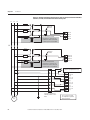
6OLTAGEAND#URRENT3ENSING#ONNECTION%XAMPLES
The following examples depict typical connections of voltage (also called
potential) transformer (VTs) and current transformers (CTs) to the CGCM unit
for various bus and generator power system configurations. These diagrams do
not show all connections to the CGCM unit, nor are they intended to show all
possible wiring combinations. For assistance in wiring a CGCM unit in a power
system configuration not shown below, please contact Rockwell Automation.
Rockwell Automation Publication 1407-UM001H-EN-P - November 2014
#HAPTER
Installation
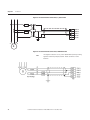
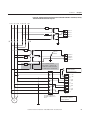
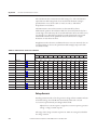
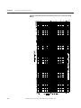
&IGURE6OLTAGEAND#URRENT#ONNECTIONFOR4WOORTHREE4RANSFORMER$ELTA"US
AND4WOORTHREE4RANSFORMER$ELTA'ENERATOR3YSTEM
L1
L2 L3
Fuse
Optional
Ground
Fuse
Fuse
VBus A
VBus B
VBus C
Use of a third potential
transformer is optional. The
CGCM unit can be connected
in either open or closed delta.
VBus N
TB 6
CB
Fuse
Optional
Ground
VGen A
VGen B
VGen C
VGen N
Fuse
Fuse
Use of a third potential
transformer is optional. The
CGCM unit can be connected
in either open or closed delta.
TB 5
To optional cross-current
reactive compensation loop.
ID(+) 1A
ID (+) 5A
ID (-)
I3 (+) 1A
I3 (+) 5A
I3 (-)
I2 (+) 1A
I2 (+) 5A
I2 (-)
I1 (+) 1A
I1 (+) 5A
I1 (-)
TB 3
B
A
G
C
Customer Supplied CT
Shorting Switch or Test
Block
Cross-current CT input
not required for parallel
droop operation.
Rockwell Automation Publication 1407-UM001H-EN-P - November 2014
Installation
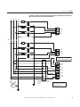
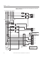
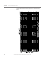
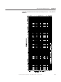
#HAPTER &IGURE6OLTAGEAND#URRENT#ONNECTIONFOR&OURWIRE7YE"USAND&OURWIRE
7YE'ENERATOR3YSTEMWITH'ROUNDED.EUTRAL
,
, , .
&USE
&USE
6"US!
6"US"
6"US#
&USE
6"US.
4" #"
&USE
&USE
6'EN!
6'EN"
6'EN#
6'EN.
&USE
4"
4OOPTIONALCROSSCURRENT
REACTIVECOMPENSATIONLOOP
)$!
)$!
)$
)!
)!
) )!
)!
) )!
)!
) "
!
'
#USTOMER3UPPLIED#4
3HORTING3WITCHOR4EST
"LOCK
#
.
4" #ROSSCURRENT#4INPUT
NOTREQUIREDFORPARALLEL
DROOPOPERATION
Rockwell Automation Publication 1407-UM001H-EN-P - November 2014
#HAPTER
Installation
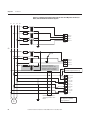
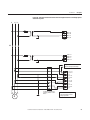
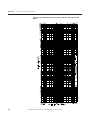
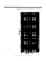
&IGURE6OLTAGEAND#URRENT#ONNECTIONFOR&OURWIRE7YE"USAND4WOOR
THREE4RANSFORMER$ELTA'ENERATOR3YSTEM
L1
L2 L3
N
Fus E
Fuse
VB u s A
VB u s B
VB u s C
Fu se
VB u s N
TB 6
CB
Fuse
Optional
Ground
Fuse
Fuse
VGe n A
VGe n B
VGe n C
VGe n N
Use of a third potential
transformer is optional. The
CGCM unit can be connected
in either open or closed delta.
TB5
To optional cross-current
reactive compensation loop.
ID (+) 1A
ID (+) 5A
ID ( -)
I3 (+) 1A
I3 (+) 5A
I3 ( -)
I2 (+) 1A
I2 (+) 5A
I2 ( -)
I1 (+) 1A
I1 (+) 5A
I1 ( -)
TB3
B
A
G
C
Customer Supplied CT
Shorting Switch or Test
Block
Cross-current CT input
not required for parallel
droop operations.
Rockwell Automation Publication 1407-UM001H-EN-P - November 2014
Installation
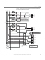
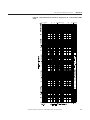
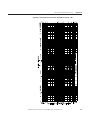
#HAPTER &IGURE6OLTAGEAND#URRENT#ONNECTIONFOR4WOORTHREE4RANSFORMER$ELTA
"USAND&OURWIRE7YE'ENERATOR3YSTEM
L1
L2 L3
Fu se
Optional
Ground
VB us A
6"us B
VB us C
Fu se
VB us N
TB 6
Fuse
Use of a third potential
transformer is optional. The
CGCM unit can be connected
in either open or closed delta.
CB
Fuse
Fuse
V Gen A
VGe n B
V Gen C
V Gen N
Fuse
TB 5
To optional cross-current
reactive compensation loop.
ID (+)
ID (+)
ID (- )
I3 (+)
I3 (+)
I3 (- )
I2 (+)
I2 (+)
I2 (- )
I1 (+)
I1 (+)
I1 (- )
1A
5A
1A
5A
1A
5A
1A
5A
TB3
B C
A
G
N
Customer Supplied CT
Shorting Switch or Test
Block
Cross-current CT input
not required for parallel
droop operation.
Rockwell Automation Publication 1407-UM001H-EN-P - November 2014
#HAPTER
Installation
&IGURE6OLTAGEAND#URRENT#ONNECTIONFOR4HREEWIRE7YE"USAND&OURWIRE
7YE'ENERATOR3YSTEMWITH'ROUNDED.EUTRAL
, , ,
&USE
&USE
6"US!
6"US"
6"US#
&USE
6"US.
4" #"
&USE
&USE
6'EN!
6'EN"
6'EN#
6'EN.
&USE
4"
4OOPTIONALCROSSCURRENT
REACTIVECOMPENSATIONLOOP
)$ !
)$ !
)$ ) !
) !
) ) !
) !
) ) !
) !
) 4" "
!
'
#
.
#USTOMER3UPPLIED#4
3HORTING3WITCHOR4EST
"LOCK
#ROSSCURRENT#4INPUT
NOTREQUIREDFORPARALLEL
DROOPOPERATION
Rockwell Automation Publication 1407-UM001H-EN-P - November 2014
Installation
#HAPTER &IGURE6OLTAGEAND#URRENT#ONNECTIONFOR$UAL"REAKER"USAND4WOORTHREE
4RANSFORMER$ELTA'ENERATOR3YSTEM
L1 A L 2A L 3 A L1 B L 2B L 3 B
Fus e
VB us A
VB us B
VB us C
Fu se
6"us N
TB 6
CB
CB
Fuse
Optional
Ground
VGen
VGen
VGen
VGen
Fuse
A
B
C
N
TB 5
Fus e
Use of a third potential
transformer is optional. The
CGCM unit can be connected
in either open or closed delta.
To optional crosscurrent reactive
compensation loop.
ID (+ ) 1A
ID (+ ) 5A
ID (-)
I3 (+ ) 1A
I3 (+ ) 5A
I3 ( -)
I2 (+ ) 1A
I2 (+ ) 5A
I2 ( -)
I1 (+ ) 1A
I1 (+ ) 5A
I1 ( -)
TB 3
B
A
G
C
Customer Supplied CT
Shorting Switch or Test
Block
Cross-current CT input
not required for parallel
droop operation.
Rockwell Automation Publication 1407-UM001H-EN-P - November 2014
#HAPTER
Installation
&IGURE6OLTAGEAND#URRENT#ONNECTIONFOR$UAL"REAKER"USAND&OURWIRE
7YE'ENERATOR3YSTEM
, ! , ! , ! ," , " ,"
&USE
6"US !
6"US "
6"US #
&USE
6"US .
4" #"
#"
&USE
&USE
6 'EN!
6 'EN"
6 'EN#
6 'EN.
&USE
4" 4OOPTIONALCROSS
CURRENTREACTIVE
COMPENSATIONLOOP
)$ !
)$ !
)$ ) !
) !
) ) !
) !
) ) !
) !
) 4" !
"
'
#
.
#USTOMER3UPPLIED#4
3HORTING3WITCHOR4EST
"LOCK
Rockwell Automation Publication 1407-UM001H-EN-P - November 2014
#ROSSCURRENT#4INPUT
NOTREQUIREDFORPARALLEL
DROOPOPERATION
Installation
#HAPTER &IGURE6OLTAGEAND#URRENT#ONNECTIONFOR3INGLE0HASE"USAND3INGLEPHASE
'ENERATOR3YSTEM
,
, ,
&USE
6"US!
6"US"
6"US#
6"US.
4" #"
6'EN !
6'EN "
6'EN #
6'EN .
&USE
4" 4OOPTIONALCROSSCURRENT
REACTIVECOMPENSATIONLOOP
)$ !
)$ !
)$ ) !
) !
) ) !
) !
) ) !
) !
) 4"
"
!
'
#
#USTOMER3UPPLIED#4
3HORTING3WITCHOR4EST
"LOCK
#ROSSCURRENT#4INPUT
NOTREQUIREDFORPARALLEL
DROOPOPERATION
Rockwell Automation Publication 1407-UM001H-EN-P - November 2014
#HAPTER
Installation
&IGURE#URRENT#ONNECTIONSFORPHASE$ELTA'ENERATORWITH4WO#4S
The connections shown in this diagram can be used if only two CTs are available
in the generator circuit. Two CTs can be used only with a three-wire delta
generator. The circuit shown in this diagram can be substituted for the CT
connections shown in Figures 9, 11, 14, and 16.
I3
I3
I3
I2
I2
I2
I1
I1
I1
(+)
(+)
( -)
(+)
(+)
( -)
(+)
(+)
( -)
1A
5A
1A
5A
1A
5A
TB 3
B
A
C
Customer Supplied CT
Shorting Switch or Test
Block
G
!UXILIARY)NPUT
The auxiliary input is a +/- 10V DC input. The auxiliary input terminals are on
TB7 and are labeled VREF(+) and VREF(-). SHLD3 is provided for landing the
cable shield. Twisted, shielded cabling is required for the VREF connections.
2EMOTE%XCITATION%NABLE)NPUT
The remote excitation enable input is a 24V DC input. The remote excitation
enable input terminals are on TB7 and are labeled EX-D(+) and EX-D(-).
$ISCRETE/UTPUTS
There are two types of discrete outputs: fault relay outputs and redundancy relay
outputs.
Rockwell Automation Publication 1407-UM001H-EN-P - November 2014
Installation
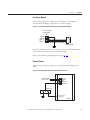
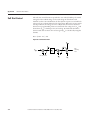
#HAPTER &AULT2ELAY/UTPUT
The fault relay output is an open-collector sinking output. The fault relay output
terminals are on TB4 and are labeled FLT. The following illustration shows a
typical connection.
&IGURE4YPICAL&AULT2ELAY#ONNECTION
2EDUNDANCY2ELAY/UTPUT
The redundancy relay output is an open-collector sinking output. The
redundancy relay output terminals are on TB4 and are labeled RD RLY. The
following figures illustrate typical redundancy connections.
&IGURE4YPICAL2EDUNDANCY6OLTAGE3ENSING#ONNECTION$IAGRAM
6"US!
6"US"
6"US#
6"US.
"US6OLTAGE
#ONNECTIONS
4"
'ENERATOR
6OLTAGE
#ONNECTIONS
6'EN!
6'EN"
6'EN#
6'EN.
4" 6"US!
6"US"
6"US#
6"US.
4" #'#-
6 'EN!
6 'EN"
6 'EN#
6 'EN.
4"
Rockwell Automation Publication 1407-UM001H-EN-P - November 2014
#'#- #HAPTER
Installation
&IGURE4YPICAL2EDUNDANCY#URRENT3ENSING#ONNECTION$IAGRAM
'ENERATOR
#URRENT
#ONNECTIONS
4" 4" #USTOMER
3UPPLIED#4
3HORTING"LOCKS
OR4EST"LOCK
) ) !
) !
4YPICALCONNECTIONFOR
ONECURRENTINPUT/THER
CURRENTINPUTSINCLUDING
THECROSSCURRENTINPUT
SHOULDDUPLICATE
#'#-
) )!
)!
#'#-
&IGURE4YPICAL2EDUNDANCY%XCITATION0OWER#ONNECTION$IAGRAM
0-' !
0-' "
0-' #
3HIELD
3HIELD
0-' 6OLTAGE
#ONNECTIONS
#'#-
4" 0-' !
0-' "
0-' #
3HIELD
3HIELD
#'#-
4"
&IGURE4YPICAL2EDUNDANCY2ELAY#ONNECTION$IAGRAM
%XCITER6OLTAGE
#ONNECTIONS
4" 3HLD
3HLD
%8# %8# "!4 "!4
&,4
2$ 2,9
#('.$
&LYBACK$IODES
%XCITER&IELD
4"
#'#-
4" 3HLD
3HLD
%8# %8# "! 4 "!4 &,4
2$2, 9
#('.$
4"
5SERPROVIDED
2ELAY
5 SERPROVIDED
2ELAY
#'#-
Rockwell Automation Publication 1407-UM001H-EN-P - November 2014
Installation
#HAPTER 2EALPOWER,OAD3HARING
The load sharing terminals connect to a 0…5V DC, internally powered circuit.
The load sharing terminals are on TB7 and are labeled LS(+) and LS(-). Terminal
SHLD4 is provided to land the cable shield. Twisted, shielded cabling is required
for the load sharing connections.
&IGURE2EALPOWER,OAD3HARING
,3 ,3 3(,$ 4" #'#- ,3 ,3 3(,$ 4"
#'#-
,3 ,3 3(, $ 4" #'#-
'ROUNDSHIELDAT
ONLYONEPOINT
#ROSSCURRENT#OMPENSATION
The Cross-current (reactive differential) Compensation Connection Diagram on
page 34 shows a typical connection diagram for three paralleled generators using
the 5 A sensing input range on the AC current input.
Make connections with 2.6 mm (10 AWG) copper wire for CT inputs.
The resistance of the cross-current CT wiring must be as low as possible. A loop
resistance less than 10% of the internal cross -current burden resistance of
1.0 7(1) enables cross-current operation with negligible voltage droop. If the
CCCT loop resistance must be higher, adjust the CCCT gain or increase the
cross-current burden resistance. You can do those things by adding external
resistance to each CGCM unit in the loop.
The cross-current compensation terminals are on TB3 and are labeled ID(-) and
ID(+). One and five ampere range terminals are provided.
(1) Series C devices have internal 1 7 resistor. Earlier devices can require an external resistor.
Rockwell Automation Publication 1407-UM001H-EN-P - November 2014
#HAPTER
Installation
&IGURE#ROSSCURRENTREACTIVEDIFFERENTIAL#OMPENSATION#ONNECTION
$IAGRAM
L 1 L2
L3
Crosscurrent CT
(typical)
ID (+ ) 1A
ID (+ ) 5A
ID (-)
A
B
G
G1
L1
L2
TB 3
Customer
Supplied CT
Shorting Switch
or Test Block
(typical)
C
L3
ID (+ ) 1 A
ID (+ ) 5 A
ID ( -)
TB 3
A
B
C
G
G2
L1
L2
L3
ID (+ ) 1 A
ID (+ ) 5 A
ID ( -)
TB 3
A
B
C
Ground
cross-current loop
at only one point
(optional).
G
G3
&IGURE4YPICAL#ROSSCURRENT#4,OCATIONSAND0OLARITY
, , ,
, , ,
#ROSS
CURRENT#4
TYPICAL
!
"
!
#
8
9 :
!"#'ENERATOR
"
'
'
8
#
:
9
!#"'ENERATOR
Rockwell Automation Publication 1407-UM001H-EN-P - November 2014
Installation
#HAPTER #OMMUNICATION#ONNECTORSAND3ETTINGS
There are three ports on the unit: the factory calibration port, the redundancy
port (COM1), and the ControlNet network port.
&ACTORY#ALIBRATION0ORT
The factory calibration port is not intended for use by anyone other than
qualified factory representatives.
2EDUNDANCY0ORT#/-
The DB-9 female connector on the bottom side of the CGCM unit is used for
communication with another CGCM unit when operating in a redundant
system configuration. Use a null modem cable for this connection.
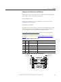
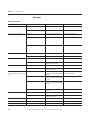
See CGCM Unit Interconnection Cable table for connector pin numbers,
functions, names, and signal directions.
The cable pin-out is illustrated in the CGCM Unit Interconnection Cable
Diagram.
4ABLE#'#-5NIT)NTERCONNECTION#ABLE
0IN
.AME
1
$ESCRIPTION
&UNCTION
Not used
2
XMIT
Transmit
Sends serial data from CGCM unit
3
RCV
Receive
Receives serial data from CGCM unit
4
DTR
Data terminal ready
Receives a signal that the sending unit is operational
5
GND
Ground
Provides the ground signal
6
DSR
Data set ready
Sends a signal that the CGCM unit is operational
7, 8, 9
Not used
&IGURE#'#-5NIT)NTERCONNECTION#ABLE$IAGRAM
To CGCM Unit
DB-9 Female
Rockwell Automation Publication 1407-UM001H-EN-P - November 2014
To CGCM Unit
DB-9 Female
#HAPTER
Installation
#ONTROL.ET.ETWORK0ORT
Two ControlNet tap cables and channel labels are included with the
1407-CGCM unit.
If redundancy is desired, use both connectors. Otherwise, you can use either
connector.
You can use the mounting fasteners provided on the right-hand side of the unit
chassis to fasten the tap cables. Minimum bend radius for the ControlNet tap
cables is 38 mm (1.5 in.). Take care not to kink or pinch the ControlNet tap cable
or bend it more sharply than the minimum radius. Panduit HLM-15RO
hook-and-loop wraps are recommended for securing the tap cable to chassis
mounts.
Use the thumbwheel switches on the front of the CGCM unit to set the
ControlNet network node address (MAC ID).
For installation procedures, please refer to ControlNet Coax Media Planning and
Installation, publication CNET-IN002.
Rockwell Automation Publication 1407-UM001H-EN-P - November 2014
#HAPTER
#'#-5NIT/PERATION
This section provides a operational description of the CGCM unit’s functions.
The CGCM unit incorporates hardware inputs and outputs, software inputs and
outputs to a Logix family programmable controller, configuration settings, and its
internal control algorithms to provide the regulation, synchronizing, and
protection functions described in this section.
For information on configuring the CGCM unit, see Chapter 4, Configuration.
For further information on the software interface between the CGCM unit and
its host Logix programmable controller, see Chapter 6, CGCM Unit Software
Interface.
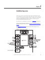
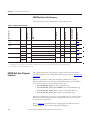
The Simplified Block Diagram provides a functional block diagram for the
CGCM unit.
&IGURE3IMPLIFIED"LOCK$IAGRAM
DC
Rockwell Automation Publication 1407-UM001H-EN-P - November 2014
#HAPTER
CGCM Unit Operation
)NPUTSAND/UTPUTS
The figure below shows the front panel layout of the CGCM unit. Input and
output connections are made through the terminal blocks TB1…TB7.
&IGURE&RONT0ANEL,AYOUT
!NALOG)NPUTS
The CGCM unit provides a number of analog inputs for use in the regulation
and control of stand-alone and paralleled generator systems. Each of the inputs is
outlined below.
'ENERATOR6OLTAGE3ENSING)NPUTS
The CGCM unit senses generator voltage through voltage transformers (VTs)
installed across the generator output leads.
Rockwell Automation Publication 1407-UM001H-EN-P - November 2014
CGCM Unit Operation
#HAPTER The CGCM unit uses voltages measured through the generator voltage sensing
inputs for generator voltage, VAR and/or power factor regulation, kW and kVAR
load sharing, synchronization, metering, and protection. The inputs accept
signals with up to 40% Total Harmonic Distortion (THD) and are connected for
single-phase and 3-phase applications. The generator voltage inputs are internally
scaled by the CGCM unit according to its transformer configuration settings.
Generator voltage sensing inputs are labeled V Gen A, V Gen B, V Gen C, and V
Gen N.
"US6OLTAGE3ENSING)NPUTS
Voltages measured through the bus voltage sensing inputs are used for generator
to bus synchronizing. The CGCM unit senses bus voltage through VTs.
Depending upon the number of busses and the type of synchronizing required,
there is one or two sets of bus sensing transformers. If dual bus synchronizing is
required, the sensing transformer configuration is limited to single-phase. In a
single breaker system the inputs are connected in either single-phase or 3-phase
configurations. The inputs accept signals with up to 40% THD. The bus voltage
inputs are internally scaled by the CGCM unit according to its transformer
configuration settings.
Bus voltage sensing inputs are labeled V Bus A, V Bus B, V Bus C, and V Bus N.
'ENERATOR,INE#URRENT
The CGCM unit senses generator current through current transformers installed
on the generator output leads.
Current measured through the line current inputs is used for metering purposes,
regulating generator vars, regulating generator PF, real power load sharing, and
for protection purposes; and is required for operation in AVR Droop, PF, and
VAR operating modes. Line current inputs are galvanically isolated via CTs
internal to the CGCM unit. The CGCM unit accepts either 1 A or 5 A current
inputs wired to the corresponding input. Line current inputs are labeled I1(+)1
A, I1(+)5 A, I1(-), and so forth.
#ROSSCURRENT
The CGCM unit senses reactive differential current through properly connected
current transformers typically installed on the B-phase output leads of each
paralleled generator.
See Typical Cross-current CT Locations and Polarity on page 34 for more
information.
Line current inputs are galvanically isolated via CTs internal to the CGCM unit.
The CGCM unit accepts either 1 A or 5 A current inputs. The cross-current
input terminals are labeled ID(+)5A, ID(+)1A, and ID(-).
Rockwell Automation Publication 1407-UM001H-EN-P - November 2014
#HAPTER
CGCM Unit Operation
!UXILIARY)NPUT
This input is an analog voltage (-10…10V DC), and provides a means to remotely
adjust the regulation point of the generator. Resistive isolation is provided
through the use of differential amplifiers.
The auxiliary input terminals are labeled VREF(+) and VREF(-).
0OWER)NPUTS
The unit has two types of power inputs: control power inputs and excitation
power inputs.
#ONTROL0OWER)NPUT
The CGCM unit operates from a nominal 24V DC supply connected to the
control power inputs. The control power input is diode-protected to protect
against equipment damage due to improper polarity of the applied power.
The control power inputs are labeled BAT(+) and BAT(-).
%XCITATION0OWER)NPUT
The CGCM unit accepts either 3-phase or single phase excitation power.
Excitation power can be obtained from the generator or the utility via shunt
excitation (SE) or from the generator prime mover via a Permanent Magnet
Generator (PMG).
See Chapter 2 for details on connections for SE or PMG operation.
The excitation power input terminals are labeled PMG A, PMG B, and PMG C.
$ISCRETE)NPUTS2EMOTE%XCITATION%NABLE
The remote excitation enable input is a 24V DC input. When 24V DC is applied
to the input, CGCM unit excitation is permitted.
)-0/24!.4
For generator excitation to occur, excitation must be enabled in software,
an active ControlNet connection must be present, and a 24V DC signal
must be applied to the remote excitation enable input.
The remote excitation enable input terminals are labeled EX-D(+) and EX-D(-).
Rockwell Automation Publication 1407-UM001H-EN-P - November 2014
CGCM Unit Operation
#HAPTER !NALOG/UTPUTS
The unit has two types of analog outputs: excitation output and real power load
sharing.
%XCITATION/UTPUT
The CGCM unit Pulse Width Modulated (PWM) power stage provides DC
generator exciter field current. The excitation power stage is designed to
accommodate up to 125V DC (nominal) field voltages.
Refer to Excitation Control Modes on page 44 for a description of operation.
Care must be taken that the field resistance does not allow more than 15 A DC to
flow continuously at rated field voltage.
Minimum resistance for common voltages is given in Appendix D.
The CGCM unit excitation output is equipped with a high-speed circuit for
detecting a shorted output. The excitation output is clamped at a very low level
when a low impedance connection is detected. The CGCM unit indicates that
the clamp is active by setting Spare2 bit in the Scheduled Read Data Table. The
Spare2 bit indication is reset by either setting the tag SoftwareExcEN = 0 or by
cycling the control power to the CGCM unit.
Note that a loss of ControlNet network communication with the host Logix
controller causes the CGCM unit to automatically shutdown generator
excitation.
The excitation output terminals are labeled EXC(+) and EXC(-).
2EALPOWER,OAD3HARING
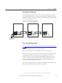
Real-power load sharing terminals are provided to allow two or more CGCM
units or other compatible generator control devices (such as the Line
Synchronization Module, catalog number 1402-LSM) to load the generators
under their control such that the same per unit output is developed by each
generator.
Load sharing terminals are labeled LS(+) and LS(-).
Rockwell Automation Publication 1407-UM001H-EN-P - November 2014
#HAPTER
CGCM Unit Operation
$ISCRETE/UTPUTS
The CGCM unit provides two discrete open collector outputs, the fault output
and the redundancy relay output. These are sinking type outputs internally
connected to the control power BAT(-) supply. They are intended to drive a
user-supplied relay connected between the control power BAT(+) supply and the
applicable discrete output terminal.
&AULT/UTPUT
The fault output can be used to annunciate a fault via a user-supplied relay. The
user chooses, from a predetermined list, the conditions for this output. The fault
output is labeled FLT.
The fault enable output tags in the Output table determine which faults activate
the fault relay output.
2EDUNDANCY2ELAY/UTPUT
The redundancy relay output is used to transfer excitation of the generator from
the primary CGCM unit to the redundant CGCM unit in dual unit systems.
The redundancy relay output is labeled RD RLY.
#OMMUNICATION
The CGCM unit provides three communication ports along with software
inputs and outputs.
#OM&ACTORY4EST0ORT
Not for customer use. This port is used to calibrate the CGCM unit during
factory testing.
#OM2EDUNDANCY0ORT
The redundancy port lets one CGCM unit communicate with its partner
CGCM unit in a redundant system, letting the partner unit auto-track the
primary unit's control modes.
#ONTROL.ET.ETWORK0ORT
The version 1.5 ControlNet network port is used to interface with a Logix family
programmable logic controller. Through this port, RSLogix 5000 software
facilitates setting CGCM unit configuration parameters. Control, metering, and
protection settings are communicated to the CGCM unit by using this port. The
CGCM unit firmware is flash programmable through this port.
Rockwell Automation Publication 1407-UM001H-EN-P - November 2014
CGCM Unit Operation
#HAPTER 3OFTWARE)NPUTSAND/UTPUTS
Your Logix family host programmable controller must include the hardware and
communication interfaces with the generator, prime mover, power system, and
balance of plant that are not specifically included in the CGCM unit module.
The software interface between the CGCM unit and its host controller is made
via the ControlNet software interface. The specific interface consists of several
assembly instances, or data tables.
• The Input (Scheduled Read) table provides time-critical status and fault
parameters, and control commands, from the CGCM unit to the host
Logix controller.
• The Output (Scheduled Write) table provides time-critical enable
commands, selection commands, and setpoints from the host controller to
the CGCM unit.
• The Unscheduled Read table provides non time critical metering data
from the CGCM unit to the host controller.
• The Unscheduled Write table provides a means to adjust selected gains and
(in firmware revision 3.x or later) energy counter presets while excitation is
enabled.
• The Configuration table contains the basic CGCM unit configuration
parameters and is automatically transferred from the host controller to the
CGCM unit on powerup and at other times when excitation is not
enabled.
Refer to Chapter 6, CGCM Unit Software Interface, for more detailed
information on the CGCM unit software interface.
/PERATIONAL&UNCTIONS
The following sections describe the operational functions of the CGCM unit.
The functions include the following:
• Excitation Control Modes
• Limiting Functions
• Protection Functions
• Synchronizing
• Real-power Load Sharing
• Metering
• Redundancy
• Watchdog Timer
Rockwell Automation Publication 1407-UM001H-EN-P - November 2014
#HAPTER
CGCM Unit Operation
%XCITATION#ONTROL-ODES
The CGCM unit controls the DC excitation current of the generator exciter
based on a number of factors, including the following:
• The selected control mode
• The configuration of the CGCM unit including gains
• Measured generator voltage and current
• The applicable setpoint or setpoints
• The value of the Auxiliary Input
• Various limiting functions
The CGCM unit offers several modes of regulation that are selected and
activated by using the software interface to the host Logix programmable
controller. An active ControlNet network connection must exist with the host
Logix controller for any regulation mode to be active.
The CGCM unit automatically shuts down excitation if one of these faults
occurs:
• Overexcitation voltage
• Reverse VAR
• Logix controller fault
'AINS
The CGCM unit regulates excitation current by using a proportional, integral,
and derivative (PID) control algorithm. The regulatory response of the CGCM
unit is determined by your gain settings. The gains for each mode include the
following:
• Proportional Gain Kp – determines the basic response to changes in
generator voltage
• Integral gain Ki – speeds the return to steady state voltage after a
disturbance
• Derivative gain Kd – speeds the initial regulator response to a disturbance
• Overall gain Kg – adjusts the coarse loop gain of the regulator
• Auxiliary Gain – adjusts the effect of the auxiliary input on the regulator
output
Please refer to Chapter 4, CGCM Unit Configuration, for more detailed
information.
Rockwell Automation Publication 1407-UM001H-EN-P - November 2014
CGCM Unit Operation
#HAPTER &IELD#URRENT2EGULATION-ODE
FCR mode provides manual control of the excitation current. In FCR mode, the
CGCM unit measures and controls its field excitation current output to maintain
the commanded field current setpoint. The FCR feedback loop includes
adjustable proportional, integral, and derivative gains. In FCR mode, automatic
voltage control, reactive power control, power factor control, over-excitation
limiting, and under-excitation limiting are disabled. To activate FCR mode:
• the gains must be set.
• FCR mode must be selected (tag AVR_FCR_Select = 1).
• the desired setpoint must be written to the FCRSetpt tag.
• excitation enabled (tag SoftwareExcEn = 1).
• remote Excitation Enable On (discrete input).
!UTOMATIC6OLTAGE2EGULATION-ODE!62
AVR mode provides automatic control of the excitation current. In AVR mode,
the CGCM unit controls field excitation current output to maintain the
commanded generator voltage setpoint. The AVR feedback loop includes
adjustable proportional, integral, and derivative gains. To activate AVR mode:
• the metering VTs must be properly connected and configured.
• the AVR gains must be set.
• AVR mode must be selected (tag AVR_FCR_Select = 0).
• the desired setpoint must be written to the AVRSetpt tag.
• excitation enabled (tag SoftwareExcEn = 1).
• remote Excitation Enable On (discrete input).
• for constant voltage control, droop must be disabled
(tag V_DroopEn = 0).
$ROOPREACTIVECURRENTCOMPENSATION
Droop (reactive current compensation) is a method of controlling reactive
current when a generator is connected in parallel with another energy source.
Droop adjusts the generator voltage in proportion to the measured generator
reactive power. The CGCM unit calculates reactive power by using the 3-phase
generator voltage and current sensing inputs. The droop adjustment represents
the percent reduction from the generator voltage setpoint when the generator
produces reactive power corresponding to rated generator kVA.
Rockwell Automation Publication 1407-UM001H-EN-P - November 2014
#HAPTER
CGCM Unit Operation
To activate droop:
• the metering CTs and generator VTs must be properly connected and
configured.
• the desired droop setpoint must be written to the V_DroopSetpt tag.
• excitation enabled (tag SoftwareExcEn = 1).
• remote Excitation Enable On (discrete input).
• the CGCM unit must be in AVR mode (tag AVR_FCR_Select = 0).
• droop must be enabled (V_DroopEn tag = 1).
• droop must be selected (Droop_CCC_Select tag = 0).
• automatic reactive power control must be disabled (tag PF_VAR_En = 0).
#ROSSCURRENT#OMPENSATION
Cross-current compensation (reactive differential compensation) is a method of
connecting multiple generators in parallel to share reactive load. Cross-current
compensation requires the connection of an additional CT into the cross-current
compensation input. The CGCM unit operates in a stand-alone application
without the cross-current inputs connected.
The cross-current compensation method of reactive load sharing is possible with
other controllers of similar type. Cross-current compensation monitors the ID
current, V GEN A, and V GEN C inputs to adjust the excitation level. A gain
adjustment is provided to allow tuning of the cross current control. Cross-current
compensation is configured and controlled by using the software interface to the
Logix controller.
To activate cross-current compensation:
• the generators must be connected in parallel.
• the cross-current CT and generator VTs must be properly connected.
• the desired cross-current gain must be written to the CrossCurrentGain
tag.
• excitation enabled (tag SoftwareExcEn = 1).
• remote Excitation Enable On (discrete input).
• the CGCM unit must be in AVR mode
(tag AVR_FCR Select = 0).
• droop must be enabled (V_DroopEn tag = 1).
• cross-current compensation must be selected (Droop_CCC_Select tag
= 1) (and KVAR_LS_En tag = 1 for firmware rev. 2.x).
When cross-current compensation is disabled or control power is removed from
the unit, the cross-current input terminals ID(+) and ID(-) are internally
connected together through a very small impedance.(1)
(1) For series B devices, the input terminals are not connected together when control power is removed.
Rockwell Automation Publication 1407-UM001H-EN-P - November 2014
CGCM Unit Operation
#HAPTER !UXILIARY)NPUT2EGULATION!DJUSTMENT
The auxiliary input provides a means to remotely adjust the regulation point of
the generator. This analog voltage (-10…10V DC) input signal changes the
setpoint of the selected operating mode by one percent of the applicable rated
value for each volt applied (positive or negative), multiplied by the auxiliary gain
setting for AVR/FCR or VAR/PF.
Refer to Chapter 4 for more information.
Auxiliary input gain settings range from -99…99. If the gains are set to zero, the
auxiliary input is inactive.
A typical use for this input is with a Power System Stabilizer where adjusting the
regulation point of the generator can increase system stability during power
system kW swings.
,INEDROP#OMPENSATION
Line-drop compensation adjusts generator voltage proportional to generator
load. Line-drop compensation can be used to maintain voltage at a load that is at
a distance from the generator. Generator output reactive current is used to
increase the generator voltage with increasing load, based on the user
configurable line-drop compensation factor. Line-drop compensation is
adjustable from 0…10% of the voltage setpoint in 0.1% steps, which represents
the percent voltage change at rated generator current. Line-drop compensation
cannot be used with droop or cross-current compensation.
0OWER&ACTOR2EGULATION-ODE0&
In PF mode, the CGCM unit controls field excitation current output to maintain
the commanded power factor setpoint. The CGCM unit uses the measured
generator voltages and currents to calculate power factor. The PF feedback loop
includes adjustable proportional and integral gains. To activate PF mode:
• the metering CTs and VTs must be properly connected and configured.
• the PF mode gains must be set.
• the desired power factor setpoint must be written to the PFSetpt tag.
• excitation enabled (tag SoftwareExcEn = 1).
• remote Excitation Enable On (discrete input).
• the CGCM unit must be in AVR mode (tag AVR_FCR_Select = 0).
• droop must be enabled (V_DroopEn tag = 1).
• droop must be selected (Droop_CCC_Select tag = 0).
• automatic reactive power control must be enabled (tag PF_VAR_En = 1).
• power factor control must be selected (tag PF_VAR_Select = 0).
Rockwell Automation Publication 1407-UM001H-EN-P - November 2014
#HAPTER
CGCM Unit Operation
2EACTIVE0OWER2EGULATION-ODE6!2
In VAR mode, the CGCM unit controls field excitation current output to
maintain the commanded reactive power setpoint. The CGCM unit uses the
measured generator voltages and currents to calculate reactive power. The VAR
feedback loop includes adjustable proportional and integral gains. To activate
VAR mode:
• the metering CTs and VTs must be properly connected and configured.
• the VAR mode gains must be set.
• the desired reactive power setpoint must be written to the VARSetpt tag.
• excitation enabled (tag SoftwareExcEn = 1).
• remote Excitation Enable On (discrete input).
• the CGCM unit must be in AVR mode (tag AVR_FCR_Select = 0).
• droop must be enabled (V_DroopEn tag = 1).
• droop must be selected (Droop_CCC_Select tag = 0).
• automatic reactive power control must be enabled (tag PF_VAR_En = 1).
• VAR control must be selected (tag PF_VAR_Select = 1).
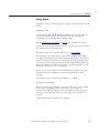
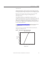
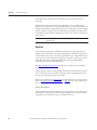
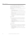
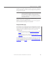
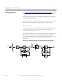
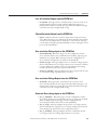
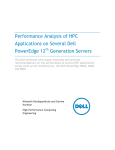
3OFT3TART-ODE
CGCM unit Soft Start mode provides for an orderly build-up of generator
voltage from residual to the voltage setpoint in the desired time with minimal
overshoot. When the system is in Soft Start mode, the CGCM unit adjusts the
voltage reference based on the Soft Start Initial Voltage and Soft Start Time.
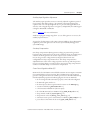
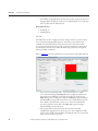
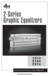
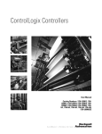
The Soft Start Voltage Reference illustration is a graph for the voltage reference
showing soft start initial voltage at 30%, soft start time at 8 seconds.
&IGURE3OFT3TART6OLTAGE2EFERENCE
Rockwell Automation Publication 1407-UM001H-EN-P - November 2014
CGCM Unit Operation
#HAPTER If the generator is not up to speed when the soft start begins, the voltage increases
but only to the level determined by Volts/Hz limiting. When the unit is operating
in FCR mode, soft start operates as it does in the AVR mode, with the field
current, rather than the generator voltage, being the controlled parameter.
To activate soft start mode:
• the Soft Start Initial Voltage (tag SoftStart_InitLevel) and Soft Start
Time (tag SoftStartTime) parameters must be set.
• excitation enabled (tag SoftwareExcEn = 1).
• remote Excitation Enable On (discrete input).
• FCR mode not active (tag AVR_FCR_Select = 0).
• engine idle bit is set (tag EngineIdle = 1).
)NTERNAL4RACKING
The CGCM unit provides a tracking function between the non-active modes of
operation and the active mode of operation, to minimize the potential for
instability that can occur when switching from one mode to another. There are
two settings you can configure. The internal tracking rate defines the time
constant of a first-order filter through which the CGCM unit matches the
non-active modes with the active mode and is scaled in seconds. The time for the
tracking function to settle out after a step change in the operating setpoint is
approximately four times the internal tracking rate setting.
The internal tracking delay setting adjusts the delay of the tracking function to
prevent a non-active mode from being adjusted into an undesirable condition.
For example, with AVR mode active, if the generator sensing VT fails open, the
excitation output goes to a full-on state. Applying a tracking delay reduces the
likelihood of this undesirable operating point being transferred to a new
operating mode.
4RAVERSE2ATES
You can control the speed at which the CGCM unit switches from one
regulation mode to another by configuring traverse rates for each regulation
mode. These settings define the rate at which the system changes to the new
setpoint when the mode changes. At the instant the mode is changed, the
regulator begins changing its operating point from the internal tracking setpoint
to the new mode's setpoint at a rate determined by the new mode's traverse rate.
Please refer to Chapter 4 for information on scaling and units of the traverse rate
settings.
Increasing a traverse rate causes the regulator output to change more slowly. A
value of 200 seconds is a special case that causes the CGCM unit to hold the
existing regulator output until the new setpoint is adjusted to become equal to or
pass through the previous mode's setpoint.
Rockwell Automation Publication 1407-UM001H-EN-P - November 2014
#HAPTER
CGCM Unit Operation
The tag SetptTraverseActive = 1 when the CGCM unit is traversing between
the internal tracking setpoint and the new operating mode's setpoint. The tag = 0
when the operating point has completed traversing to the new mode's setpoint.
This tag is used by the host Logix controller to determine when the new mode
has taken control.
,IMITING&UNCTIONS
This section discusses the different types of limiting functions the CGCM unit
provides.
• Volts/Hertz Limit
• Over-excitation Limit
• Under-excitation Limit
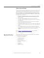
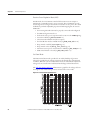
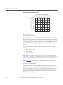
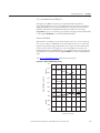
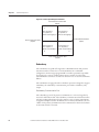
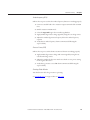
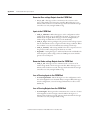
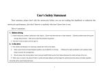
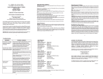
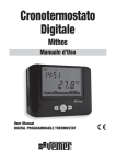
'ENERATOR#APABILITY#URVE
The generator capability curve graphically depicts the combinations of real and
reactive power a generator is able to produce (or absorb, in the case of reactive
power) without damage caused by overheating. The CGCM unit provides a
number of limiting functions designed to maintain operation within safe areas of
the generator capability curve.
A typical generator capability curve is shown in the following illustration.
&IGURE4YPICAL'ENERATOR#APABILITY#URVE
,AGGING
&IELD7INDING
(EATING,IMITATION
2ATING0&
,AGGING
!RMATURE7INDING
2EACTIVE0OWERPER5NIT
(EATING,IMITATION
0RIME-OVER
0OWER,IMITATION
0&
,EADING
,EADING
!RMATURE#ORE
%ND)RON(EATING
,IMITATION
2EAL0OWERPER5NIT
Rockwell Automation Publication 1407-UM001H-EN-P - November 2014
CGCM Unit Operation
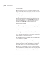
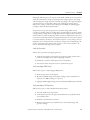
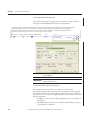
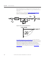
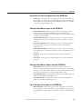
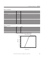
#HAPTER 6OLTS(ERTZ,IMIT
Volts/Hertz limiting acts to reduce the generator output voltage by an amount
proportional to generator frequency. This is done to protect the generator from
overheating and reduce the impact on the prime mover when adding a large load.
When the generator frequency drops, the voltage setpoint is automatically
adjusted by the CGCM unit so that generator voltage follows the
under-frequency slope.
The CGCM unit provides two configurable knee frequencies and two
configurable slopes that allow the user to define the Volts/Hz characteristic. The
slopes are expressed in PU Volts / PU Hertz. For a nominal 60 Hz, 120V system,
a slope of one corresponds to 2V per Hz. The generator output voltage is
maintained at the configured level for any frequency at or above the configured
knee frequency up to 90 Hz. Excitation is inhibited when the frequency is at or
below the 10 Hz cutoff frequency.
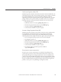
The Under-frequency Slope and Knee Voltages graph shows a typical Volts/Hz
characteristic as displayed in the RSLogix 5000 software CGCM unit
configuration screen.
Volts/Hertz limiting is automatically enabled in AVR mode and limits the
voltage increase in Soft Start mode.
&IGURE5NDERFREQUENCY3LOPEAND+NEE6OLTAGES
5NDERFREQUENCY3LOPE
6OLTAGE
&REQUENCY(Z
Rockwell Automation Publication 1407-UM001H-EN-P - November 2014
#HAPTER
CGCM Unit Operation
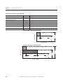
/VEREXCITATION,IMIT
Over-excitation limiting (OEL) operates in all modes except FCR. The CGCM
unit senses and limits the field current to prevent field overheating. When the
limit is reached, the limiter function overrides AVR, VAR, or Power Factor
modes to limit field current to the preset level. OEL operates in the area above
the Field Winding Heating Limitation curve in the generator capability curve.
The generator operates in one of two different states, offline or online. The
generator is offline when it is operating in a constant-voltage mode. The CGCM
unit is considered online if any of these modes are enabled:
• Droop (reactive power) compensation
• Cross current compensation
• Line drop compensation
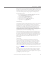
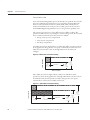
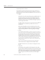
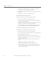
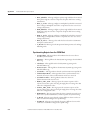
Two OEL current levels, high and low, are defined for offline operation as shown
in the graph below. The generator can operate continuously at or below the low
OEL current level and for a time at the high OEL current level that you
configure.
&)%,$#522%.4
&IGURE/FFLINE/VEREXCITATION,IMITING
High
Current
Time
0…10 seconds
CONTINUOUS
Low
Current
Level
0…15 A dc
High
Current
Level
0…30 A dc
TIME IN SECONDS
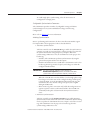
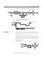
Three OEL current levels, high, medium, and low are defined for online
operation as shown in the graph below. The high and medium current levels can
be maintained only for time periods you define. The generator can operate
continuously at or below the low OEL current level.
FIELD CURRENT
&IGURE/NLINE/VEREXCITATION,IMITING
(IGH
Current
Time
0…10 seconds
Medium
Current
Time
0…120 seconds
CONTINUOUS
TIME IN SECONDS
Rockwell Automation Publication 1407-UM001H-EN-P - November 2014
Low
Current
Level
0.0…15 A dc
Medium
Current
Level
0.0… 20 A dc
High
Current
Level
0.0…30 A dc
CGCM Unit Operation
#HAPTER The CGCM unit also uses two counters, the reset counter and the time limit
counter. The counters are used to prevent excessive heating of the exciter field
that can be a result of repeated over-excitation. The time limit counter monitors
the duration of an over-excitation condition. The reset counter counts backward
from either the high OEL time setting or the sum of the high and medium OEL
times, depending on the value of the time limit counter.
If, during an OEL cycle, excitation current returns below the low current value,
the reset counter begins counting backwards from its present value. If it reaches
zero, the time limit counter is reset to zero and a new OEL cycle can then occur.
If the reset counter does not reach zero before the excitation current rises above
the low current value, the time limit counter begins counting where it stopped
when the excitation current last fell below the low current value. If the time limit
counter is greater than the programmed high OEL time, the excitation current is
limited to the medium current value. This prevents repeated cycling of the exciter
field at its highest possible current value.
When the excitation current exceeds the OEL limit, the OEL alarm tag
OEL_Active = 1. In FCR mode, OEL limiting is not active although the tag is
set. This tag is in the Scheduled Read table. The OEL function meets
ANSI/IEEE C50.13.
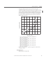
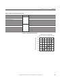
5NDEREXCITATION,IMIT
Under-excitation limiting (UEL) operates in all modes except FCR mode. UEL
senses the leading var input of the generator and limits any further decrease in
excitation to prevent loss of synchronization and excessive end-iron heating
during parallel operation. UEL operates in the area below the Armature Core
End Iron Heating Limitation curve in the generator capability curve.
4)0
The UEL function is not designed to prevent the loss of excitation
function from operating.
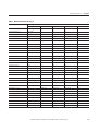
A customizable UEL limiting curve is defined by a piecewise linear curve
specified by five points you select as shown in the Typical UEL Limiting Curve
diagram.
Generator is operating in the area of its characteristic curve below the UEL curve,
when the excitation current is less than the UEL curve, the UEL alarm tag
UEL_Active = 1. In FCR mode, UEL limiting is not active although the tag is
set. This tag is in the Scheduled Read table.
Rockwell Automation Publication 1407-UM001H-EN-P - November 2014
#HAPTER
CGCM Unit Operation
&IGURE4YPICAL5%,,IMITING#URVE
2EAL0OWER'ENERATE7X
K K K K K K
2EACTIVE0OWER!BSORBVARX
K
K
K
K
K
K
0ROTECTION&UNCTIONS
The CGCM unit detects the fault conditions listed and described below. Faults
detected by the CGCM unit are communicated to the host Logix programmable
controller. Fault flags are communicated in the Scheduled Read table. A fault flag
is latched until the host controller resets it. The host Logix controller can reset all
CGCM unit faults by setting the tag FltReset = 1 once the fault condition is
cleared.
The CGCM unit automatically shuts down excitation if one of these faults
occurs:
• Overexcitation voltage
• Reverse VAR
• Logix controller fault
Fault conditions can also be configured to activate the CGCM unit fault relay
output. Once configured, the CGCM unit fault relay operates independently of
the host Logix controller program (including Controller Run/Program mode).
Refer to Chapter 4 for information on configuring the fault relay operation.
#'#-0ROTECTION#APABILITIES
The protective functions in the CGCM unit are time-proven and designed to
provide a high degree of reliability, repeatability, longevity, and accuracy. The
CGCM unit is designed to meet or exceed applicable CE standards, but was not
tested to all standards that many North American utilities use to define utility
grade protection. However, the CGCM unit does possess many of the features
that define utility grade protection.
Rockwell Automation Publication 1407-UM001H-EN-P - November 2014
CGCM Unit Operation
#HAPTER The CGCM unit can be used as primary protection in applications not requiring
utility grade protection or in utility applications where the authority having
jurisdiction has approved the CGCM unit for use as primary protection. In
applications requiring utility grade protection, where the local authority has not
evaluated or approved the CGCM unit, the CGCM unit can be used for
secondary protection in conjunction with a primary protection system.
,OSSOF%XCITATION#URRENT
The CGCM unit activates this fault when excitation current metered by the
CGCM unit falls below the user specified loss of excitation current setpoint for
more than the user defined delay time. In a redundant CGCM unit system,
excitation is disabled and a transfer to the secondary controller occurs. If this fault
occurs, tag LossExcFlt = 1 in the Scheduled Read table. This fault is inhibited
during voltage build and when soft start is active.
/VEREXCITATION6OLTAGE&FIELDOVERVOLTAGE
When the field voltage rises above the level you specified for more than a set
amount of time, a field over-voltage annunciation occurs. Once the field voltage
drops below the threshold, the field over-voltage timer is reset. If this fault occurs,
the CGCM unit shuts down excitation and sets tag OvrExcFlt = 1 in the
Scheduled Read table.
'ENERATOR/VERVOLTAGE
When the generator voltage rises above the level you specified for more than a set
amount of time, a generator over-voltage annunciation occurs. Once the
generator voltage drops below the threshold, the generator over-voltage timer is
reset. If this fault occurs, tag
Ovr_V_Flt = 1 in the Scheduled Read table.
'ENERATOR5NDERVOLTAGE
When the generator voltage falls below the level you specified for more than a set
amount of time, a generator under-voltage annunciation occurs. Once the
generator voltage rises above the threshold, the generator under-voltage timer is
reset. This function is disabled during soft start timing or when the EngineIdle
tag is set. If this fault occurs, tag Undr_V_Flt = 1 in the Scheduled Read table.
Rockwell Automation Publication 1407-UM001H-EN-P - November 2014
#HAPTER
CGCM Unit Operation
,OSSOF3ENSING&,
For three-wire and four-wire sensing, Loss of Sensing detection is based on the
logical combination of several conditions. They include these conditions:
1. The average positive sequence voltage is greater than 8.8% of the AVR
setpoint.
2. The negative sequence voltage is greater than 25% of the positive sequence
voltage.
3. The negative sequence current is less than 17.7% of the positive sequence
current.
4. The positive sequence current is less than 1% of rated current for
0.1 seconds.
5. The generator positive sequence voltage is less than 8.8% of the AVR
setpoint.
6. The positive sequence current is less than 200% of the rated current for
0.1 seconds.
The three phase loss of sensing is expressed by this logical formula:
Loss of Sensing = ((1 and 2) and (3 or 4)) or (5 and 6)
For single-phase sensing, Loss of Sensing is detected when the following
conditions exist in the proper logical combination.
1. The average generator terminal line-to-line voltage is less than 70% of the
AVR setpoint.
2. The positive sequence current is less than 200% of the rated current.
3. The negative sequence current is less than or equal to 17.7% of the positive
sequence current.
4. The positive sequence current is less than 1% of rated current for
0.1 seconds.
The single phase loss of sensing is expressed by this logical formula:
Loss of Sensing = ((1 and 2) and (3 or 4))
The time delay for this function is fixed at 0.1 seconds during normal operation
and increased to 1.0 seconds during soft start operation. Loss of Sensing is
disabled when the excitation current is less than the Loss of Excitation setpoint. If
this fault occurs, tag LossSensingFlt = 1 in the Scheduled Read table.
Rockwell Automation Publication 1407-UM001H-EN-P - November 2014
CGCM Unit Operation
#HAPTER ,OSSOF%XCITATION0OWER0-'
If voltage to the PMG excitation power inputs falls below 10V AC for
approximately 400 ms or more, a Loss of Excitation power fault occurs. When
single phase PMG is selected, the CGCM unit senses phases A and C for this
function. This function is disabled when Shunt excitation is selected, the
EngineIdle tag is set, or the host Logix controller is in Program mode. If this fault
occurs, tag LossPMGFlt = 1 in the Scheduled Read table.
2EVERSE6!21
When the Reverse VAR level exceeds the characteristic curve for an amount of
time you set, a Reverse VAR fault occurs. The characteristic curve is a line that
begins at the pickup setting you defined at zero real power and extends toward
positive reactive power at an angle of 8°. Once the VARs increase above the
threshold, the Reverse VAR fault timer is reset. If this fault occurs, the CGCM
unit shuts down excitation and sets tag RevVARFlt = 1 in the Scheduled Read
table.
The Reverse VAR Characteristic graph shows more details.
&IGURE2EVERSE6!2#HARACTERISTIC
,AGGING
2EACTIVE0OWERPER5NIT
'ENERATOR
#HARACTERISTIC
#URVE
ª
2EVERSE6!2
4RIP3ETTING
,EADING
4RIP2EGION
2EAL0OWERPER5NIT
Rockwell Automation Publication 1407-UM001H-EN-P - November 2014
#HAPTER
CGCM Unit Operation
/VERFREQUENCY/
When generator frequency exceeds the over-frequency setpoint for a specified
amount of time, a definite time over-frequency fault occurs. Once the frequency
drops below the threshold, the over-frequency fault timer is reset. If this fault
occurs, tag OvrFreqFlt = 1 in the Scheduled Read table.
5NDERFREQUENCY5
When generator frequency drops below the under-frequency setpoint for a
specified amount of time, a definite time under-frequency fault occurs. This
function is disabled during soft start timing, when no voltage is present on the
generator voltage sensing inputs, or when the EngineIdle tag is set. Once the
frequency rises above the threshold, the under-frequency fault timer is reset. If
this fault occurs, tag UndrFreqFlt = 1 in the Scheduled Read table.
2EVERSE0OWER0ROTECTION2
When generator reverse power exceeds the reverse power setting for a specified
amount of time, a reverse power fault occurs. Once the reverse power drops below
95% of the threshold, the reverse power fault timer is reset. If this fault occurs, tag
RevPwrFlt = 1 in the Scheduled Read table.
2OTATING$IODE&AILURE
The Rotating Diode Monitor is capable of detecting one or more open or shorted
diodes in the generator’s rotor. If a failed diode is detected, a fault occurs.
The CGCM unit monitors specific harmonic components present in the field
current. The frequency of the harmonics is proportional to the system frequency
and the ratio between the main and exciter field poles.
For example, during normal operation at 60 Hz, a 3-phase exciter bridge produces
a ripple current frequency of 1080 Hz.
1080 Hz = 6 * 60Hz * (12 exciter poles / 4 main poles)
A shorted diode produces increased ripple current at 1/6 of the normal ripple
frequency or 180 Hz. Similarly, an open diode shows increased current at 1/3 of
the normal ripple frequency or 360 Hz. The CGCM unit senses harmonics in
the 1/6 and 1/3 harmonic levels to provide protection for these conditions.
When the ripple current at one of these frequencies exceeds the applicable user
specified threshold, a timer is started. Once the time delay is exceeded, a rotating
diode fault occurs. If the ripple current falls below the threshold (configured as
percent of measured excitation current) before the timer expires, the timer is
reset. If this fault occurs, tag RotDiodeFlt = 1 in the Scheduled Read table.
Rockwell Automation Publication 1407-UM001H-EN-P - November 2014
CGCM Unit Operation
#HAPTER The Rotating Diode fault is inhibited if the field current is less than
1.5 A DC or if the generator frequency is outside the range of 45…70 Hz.
0HASE2OTATION&AULT
The CGCM unit calculates the negative sequence voltage of the 3-phase
generator voltage sensing input. When the generator phase rotation is opposite to
the wiring rotation you configured, the level of the generator negative sequence
voltage increases to approximately 100%. The pickup value for this function is
fixed at 66%. When the pickup value is exceeded, timing is started. After a one
second delay a phase rotation fault is indicated. A phase rotation fault is also
indicated when a phase loss condition occurs. If this fault occurs, tag
PhRotFlt = 1 in the Scheduled Read table.
'ENERATOR/VERCURRENT6
A generator over-current fault occurs when generator current exceeds the
generator over-current function’s setpoint. You configure over-current protection
by selecting a time characteristic curve, an over-current setpoint, a time dial
setting and a voltage restraint setpoint. The over-current function meets
ANSI/IEEE C37.112.
See Appendix A for a list of available curves and more detail.
If this fault occurs, tag Ovr_I_Flt = 1 in the Scheduled Read table.
3YNCHRONIZING
The CGCM unit monitors the generator and bus voltage sensing inputs to
provide synchronization between the generator and either of two buses. The
CGCM unit provides voltage, phase and frequency error parameters, and a
breaker close permissive signal, to its host Logix controller. This lets the
controller control the prime mover, achieve phase synchronization, and voltage
matching.
The CGCM unit can also provide synchronization between two busses by
measuring appropriate synchronization parameters. For synchronizing between
two busses, substitute the term second bus for generator in the discussions that
follow.
When synchronizing a system between systems with differing metering
configurations, the synchronization configuration must account for any phase
shift or voltage differences between the two systems. For example, when
synchronizing a three-wire (delta) generator to four-wire (wye) bus system, the
synchronization configuration must take into account the 30° phase shift
between line-to-line and line-to-neutral voltage.
Rockwell Automation Publication 1407-UM001H-EN-P - November 2014
#HAPTER
CGCM Unit Operation
3YNCHRONIZING#ONNECTION3CHEMES
The CGCM unit provides information that its host Logix controller uses to
synchronize the generator output voltage, frequency, and phase to a reference
power system, or bus. 3-phase, dual bus, and single-phase connection schemes are
described below.
• 3-phase
In this scheme, the 3-phase output of the generator and all three phases of
the reference system are connected to the CGCM unit. This lets the
CGCM unit match voltage, frequency, phase, and phase rotation of the
generator to the reference system. The 3-phase scheme provides the
CGCM unit with the most power system data, allowing it to perform the
most thorough synchronization.
To enable a 3-phase connection, the user selects the Generator and Bus VT
Configurations as two-transformer open-delta, three-wire wye or
four-wire wye.
When synchronizing delta systems, the CGCM unit uses line-to-line
voltage for voltage, frequency and phase matching. When synchronizing
wye systems, the CGCM unit uses line-to-line voltage for voltage and
frequency matching, and line-to-neutral voltage for phase matching.
• Dual Bus
The CGCM unit has the ability to synchronize a generator to either one
of two reference busses. The CGCM unit supports this by monitoring one
line-to-line phase of the two reference busses. The user must select the
appropriate bus for synchronization. It is not possible to synchronize to
two different busses at the same time. For dual-bus synchronization, the
3-phase output of the generator and a single phase from each reference bus
are connected to the CGCM unit. This lets the CGCM unit match
voltage, frequency, and phase, but not phase rotation of the generator to
the reference system.
However, the CGCM unit verifies that the generator output phase
rotation matches the user-configured selection of ABC or ACB.
To enable the dual-bus mode, select the Bus VT Configuration as Dual
Breaker.
• Single-phase
The CGCM unit is also capable of synchronizing where only a single
line-to-line input is available from the generator or bus. This is the case for
single-phase systems or in systems where only one phase has a transformer
connected for synchronizing purposes. The CGCM unit can perform no
phase rotation check on the generator output with single-phase generator
voltage sensing. The reference bus connection can be either single or
3-phase.
Rockwell Automation Publication 1407-UM001H-EN-P - November 2014
CGCM Unit Operation
#HAPTER To enable single-phase synchronizing, select the Generator VT
Configuration as Single-phase.
#ONFIGURABLE3YNCHRONIZATION0ARAMETERS
The CGCM unit provides a number of configurable settings to facilitate
synchronizing between systems with different voltages and metering
configurations.
Please refer to Chapter 4 for more information.
)NITIATING3YNCHRONIZATION
Prior to performing synchronization, the host controller must initialize tags in
the Output table to their appropriate values as described below.
• Automatic Synchronization
The host controller sets the AutoSyncEn tag to enable the synchronizer to
compute error and correction tags in the software interface for control of
the synchronization bus voltage, frequency, and phase. When the
synchronizing conditions are met, the CGCM unit sets the proper close
breaker tag.
– Dual bus: The CGCM unit performs synchronization by using the
generator bus inputs and the active bus inputs.
– Dead bus: If dead bus closure is enabled, the CGCM unit sets the close
breaker tag when the generator frequency and voltage are within the
configured dead bus limits.
)-0/24!.4
Prior to Host FRN 4.9, regardless of the setting of the
$EADBUS'EN&REQ,O,IMIT parameter, the CGCM unit disables
synchronization when the generator frequency is below 45 Hz.
When the CGCM unit senses that all three (one for single phase setup)
bus voltages are less than 10% of the configured voltage and frequency
is less than 20 Hz, it sets the Dead Bus Synchronizing mode tag. The
CGCM unit does not calculate voltage or frequency error signals
during Dead Bus mode.
– Phase rotation (3-phase connection only): If the bus and generator are
opposite in phase rotation, synchronization fails. The CGCM unit
continually checks phase rotation match when synchronization is
active.
• Permissive Synchronization
The host controller sets the PermissiveSyncEn tag to enable Permissive
Synchronization mode. This mode is the same as Automatic Synchronizing
mode except that the CGCM unit does not compute error and correction
tags. The CGCM unit sets the proper close breaker tag when the
synchronizing conditions are met.
Rockwell Automation Publication 1407-UM001H-EN-P - November 2014
#HAPTER
CGCM Unit Operation
• Check Synchronization
The host controller sets the CheckSyncEn tag to enable Check
Synchronization mode. This mode is the same as the Automatic
Synchronization mode except the CGCM unit does not set a close breaker
tag. This mode is useful for testing the system.
• Initiate Synchronization
The host Logix controller sets the InitiateSync tag to begin the
synchronization process. This tag must remain set during the entire
process. If the initiate synchronization tag is reset, the CGCM unit
terminates the synchronization process. Similarly, a write of the
Unscheduled Write table terminates an active synchronization process.
The Initiate Synchronization tag enables the operation of the selected
Synchronizing mode. The host controller must select one and only one of
the three modes described above before or at the same time as the Initiate
Synchronization tag. If none are enabled, the CGCM unit sets the
undefined Synchronization mode error flag. If more than one of these
inputs is enabled, the CGCM unit sets the conflict error flag. In either
case, synchronization fails and the CGCM unit sets the synchronization
failure flag.
3YNCHRONIZING%RROR#ALCULATION
When Synchronization is active, the CGCM unit computes synchronizing errors
as follows.
Bus Voltage – Generator Voltage
Voltage Match Error = 100 s -------------------------------------------------------------------------------Bus Voltage
Frequency Match Error = Bus Frequency – Generator Frequency
Phase Match Error = Bus Voltage Phase Angle in Degrees
– Generator Voltage Phase Angle in Degrees
Rockwell Automation Publication 1407-UM001H-EN-P - November 2014
CGCM Unit Operation
#HAPTER 3YNCHRONIZING#ONTROL3OFTWARE)NTERFACE
When synchronization is active, the CGCM unit adjusts the values of the
Scheduled Read table tags as described below.
• Voltage Match Error as computed above
• Frequency Match Error as computed above
• Phase Match Error as computed above
• Voltage Raise and Lower tags, which are set when the voltage match error
is above or below, respectively, the voltage acceptance window as defined
by the configured synchronizing voltage high and low limits
• Frequency Raise and Lower tags, which are set when the frequency match
error is above or below, respectively, the frequency acceptance window as
defined by the configured synchronizing frequency high and low limits
• Phase Raise and Lower tags, which are set when the phase match error is
above or below, respectively, the phase acceptance window as defined by
the configured synchronizing phase high and low limits
• The applicable Close Breaker tag, which is set when the voltage match
error, frequency match error and phase match error have all remained
continuously within their respective acceptance windows for the
configured acceptance window delay time
2EALPOWER,OAD3HARING
The real-power load sharing function lets two or more CGCM units or other
compatible generator control devices (such as the Line Synchronization Module,
bulletin number 1402-LSM) to load the generators under their control such that
the same per unit output is developed by each generator. A 0…5V DC signal is
developed proportional to the per unit kW output of the generator and fed to the
load sharing terminals through an internal resistor. The configurable full-scale
voltage corresponds to the rated generator kilowatts. The load sharing output is
updated every 50 ms.
The load sharing terminals are connected in parallel (plus to plus, minus to
minus) with other compatible devices. If the CGCM unit’s generator is more
heavily loaded than the others, its developed load share voltage is higher, and
current flows out of the CGCM unit and into other devices on the network. A
more lightly loaded generator results in a lower load share voltage and current
flowing into the CGCM unit.
The direction and magnitude of current flow is used to develop the Load Share
Error value the CGCM unit makes available to the host logic controller. The host
logic controller program can use this value to control the prime mover governor
and balance generator output with others in the system.
The CGCM unit exhibits two rate of change features, Limit and Rate, that work
together to protect against an unstable system.
Rockwell Automation Publication 1407-UM001H-EN-P - November 2014
#HAPTER
CGCM Unit Operation
Limit defines the maximum per unit load share error reported to the host
controller.
Rate defines the maximum change in the load share error per CGCM unit
update cycle, expressed in percent of rated kilowatts per second. For example, if a
change of load of 50% is required and the rate set for 10% per second, the change
takes 5 seconds to complete. The CGCM unit has an internal relay that isolates
the load share circuit whenever the function is not active or when control power
is not present.
)-0/24!.4
Series B units do not isolate when control power is lost. An external relay
must be used.
-ETERING
The CGCM unit provides true RMS metering based on voltage and current
samples obtained from the current and voltage inputs. All monitored parameters
are derived from these values. Accuracy is specified as a percentage of full scale, at
25 °C (77 °F) across the frequency range of the controller, at unity power factor.
Metered parameters are communicated to the host Logix programmable
controller via the Unscheduled Read table.
The Metered Parameter Accuracy table lists all metered parameters and their
accuracy.
3-phase generator side metering is independent of the Synchronization mode in
one or two breaker schemes. In the two-breaker scheme, single-phase bus side
metering is provided only for the selected bus.
Refer to the Specifications, Appendix D, for information on metering accuracy.
Refer to Power System Sign Conventions on page 66 for the sign convention of
power and current values.
-ETERED0ARAMETERS
The CGCM unit provides the following metered parameters. The collection of
metering data is dependent on the metering wiring mode selected, for example,
single-phase, open-delta, four-wire wye, and three-wire wye.
Rockwell Automation Publication 1407-UM001H-EN-P - November 2014
CGCM Unit Operation
#HAPTER 4ABLE-ETERED0ARAMETER!CCURACY
-ETERED0ARAMETER
-ETERING7IRING-ODE
3INGLEPHASE
$ELTA
4HREEWIRE7YE
&OURWIRE7YE
$UALBUS
Gen Voltages, 3, L-L
CA
AB, BC, CA
AB, BC, CA
AB, BC, CA
-
Gen Voltage, avg, L-L
Yes (=CA)
Yes
Yes
Yes
-
Gen Voltages, 3, L-N
N/A
N/A
N/A
A, B, C
-
Gen Voltage, avg, L-N
N/A
N/A
N/A
Yes
-
Gen Currents, 3
A, B, C
A, B, C
A, B, C
A, B, C
-
Gen Current, avg
Yes
Yes
Yes
Yes
-
Gen Kilowatts, 3
N/A
N/A
N/A
A, B, C
-
Gen Kilowatts, total
Yes
Yes
Yes
Yes
-
Gen kVA, 3
N/A
N/A
N/A
A, B, C
-
Gen kVA, total
Yes
Yes
Yes
Yes
-
Gen kVAR, 3
N/A
N/A
N/A
A, B, C
-
Gen kVAR, total
Yes
Yes
Yes
Yes
-
Gen Power Factor, 3
N/A
N/A
N/A
A, B, C
-
Gen Power Factor, avg
Yes
Yes
Yes
Yes
-
Gen Frequency
Yes
Yes
Yes
Yes
-
Excitation Current
Yes
Yes
Yes
Yes
-
Gen Kilowatt Hours
Yes
Yes
Yes
Yes
-
Gen kVAR Hours
Yes
Yes
Yes
Yes
-
Gen kVA Hours
Yes
Yes
Yes
Yes
-
Diode Ripple Level
Yes
Yes
Yes
Yes
-
Load Share Error
Yes
Yes
Yes
Yes
-
Voltage Match Error
(1)
(1)
(1)
(1)
(1)
Sync Phase Error
(1)
(1)
(1)
(1)
(1)
Sync Frequency Error
(1)
(1)
(1)
(1)
(1)
Bus Voltages, 3, L-L
CA
AB, BC, CA
AB, BC, CA
AB, BC, CA
N/A
Bus Voltage, avg, L-L
Yes (=CA)
Yes
Yes
Yes
Yes
Bus Voltages, 3, L-N
N/A
N/A
N/A
A, B, C
N/A
Bus Voltage, avg, L-N
N/A
N/A
N/A
Yes
N/A
Bus A Frequency
Yes
Yes
Yes
Yes
Yes
Bus B Frequency
N/A
N/A
N/A
N/A
Yes
Gen Phase Rotation
N/A
Yes
Yes
Yes
Yes
Bus Phase Rotation
N/A
Yes
Yes
Yes
N/A
(1) Results updated only while Synchronization is active (tag )NITIATE3YNC = 1).
Rockwell Automation Publication 1407-UM001H-EN-P - November 2014
#HAPTER
CGCM Unit Operation
&IGURE0OWER3YSTEM3IGN#ONVENTIONS
&ORWARD2EACTIVE0OWER&LOW
EXPORT
))
)
WATTSNEGATIVE
WATTSPOSITIVE
VARSPOSITIVE
VARSPOSITIVE
POWERFACTORLAGGING POWERFACTORLAGGING
&ORWARD2EAL0OWER&LOW
EXPORT
2EVERSE2EAL0OWER&LOW
IMPORT
WATTSNEGATIVE
VARSNEGATIVE
POWERFACTORLEADING
WATTSPOSITIVE
VARSNEGATIVE
POWERFACTORLEADING
)))
)6
2EVERSE2EACTIVE0OWER&LOW
IMPORT
2EDUNDANCY
The CGCM unit is capable of being used in a Redundant mode that provides
automatic transfer of control to a second CGCM unit. In a redundant
configuration, the host Logix programmable controller is primarily responsible
for sensing power system conditions that require a transfer of control. The
CGCM unit also can initiate a transfer of control in case of certain CGCM unit
failures.
The CGCM unit is equipped with two hardware provisions designed to support
redundancy, the redundancy communication port and the redundancy relay
output.
2EDUNDANCY#OMMUNICATION0ORT
The redundancy ports of the partner CGCM units are connected together by
means of a null modem cable. The redundancy communication channel is used to
exchange tracking information from the primary to the secondary CGCM unit
to support a bumpless transfer. In addition, the secondary CGCM unit can sense
a failure in the primary CGCM unit via this communication channel to facilitate
an automatic transfer of control.
Rockwell Automation Publication 1407-UM001H-EN-P - November 2014
CGCM Unit Operation
#HAPTER If a loss of communication between redundant CGCM units occurs, the primary
CGCM unit remains primary and the secondary CGCM unit switches to
primary also. Because in this state both units are supplying current to the field, the
host Logix programmable controller must be programmed to take corrective
action (for example disable excitation to one CGCM unit) when this condition
occurs.
2EDUNDANCY2ELAY/UTPUT
The redundancy relay output is energized (sinks current) when the CGCM unit
is in Primary mode. If the CGCM unit experiences a failure or operates in
Secondary mode, the redundancy output is de-energized. The output is used to
energize your relay that connects excitation output of the primary CGCM unit to
the generator field.
When the excitation outputs from two CGCM units are connected through
relays to the generator exciter field, you must place flyback diodes across the
generator field winding to provide a path for exciter current during a transfer. To
prevent errors in field current measurement, place three or four diodes in series. If
fewer diodes are used, the field current splits between the external diode and the
internal circuitry and prevent the current measurement circuit from sensing the
total field current.
2EDUNDANCY/PERATION
CGCM units in a redundant system must both be connected to the generator
and bus VTs and the generator and cross-current CTs, as applicable. Connect the
units excitation outputs through the relays you provide to the generator exciter
field. In addition, properly connect the redundancy communication cable and
verify that the CGCM unit configurations match.
CGCM units used in a redundant configuration are normally designated as
primary and secondary, depending on the order in which the host controller
enables excitation. With excitation disabled, each CGCM unit starts out in a
Secondary mode. When the host controller enables excitation on the first
CGCM unit, it checks for tracking information on the redundancy
communication channel. If no tracking information is received, the CGCM unit
switches to Primary mode. When the host controller subsequently enables
excitation on the secondary CGCM unit, it begins receiving tracking
information and remains in Secondary mode. The primary CGCM unit
indicates its status by setting the Spare1 tag in the software interface to the host
controller.
If the primary CGCM unit fails or if its excitation is disabled, it stops sending
tracking data on the redundancy communication channel. When the secondary
senses a loss of tracking data it automatically switches to Primary mode and takes
over-excitation control. It remains primary until the host controller disables its
excitation.
Rockwell Automation Publication 1407-UM001H-EN-P - November 2014
#HAPTER
CGCM Unit Operation
Once the primary and secondary CGCM unit roles have been established by the
host controller, they remain in their respective modes indefinitely. You can force a
transfer by disabling excitation on the primary unit. This causes the secondary
unit to sense a loss of tracking information, switch to Primary mode, and take
over-excitation control.
Following a transfer, if the original failed primary CGCM unit is repaired and
returned to service, it detects tracking information from the primary unit and
remain in Secondary mode. In this state it is capable of taking over if the primary
unit fails.
In a typical redundant CGCM unit application, the host Logix controller
determines the generator's offline or online status by monitoring the status of the
generator breaker. When operating offline, the CGCM unit normally regulates
generator voltage in AVR mode. The host controller monitors generator voltage
and other conditions. If those conditions indicate a failure of the primary unit the
host controller initiates a transfer by disabling excitation to the primary unit. The
secondary unit senses the loss of tracking information from the primary unit,
designate itself the primary, energize its redundancy relay output and take
over-excitation control.
When operating online, that is with the generator breaker closed and the
generator operating in parallel with other generators or the power grid, the
CGCM unit normally operates in VAR or PF mode to regulate reactive power
flow. The host controller monitors generator conditions as in the offline
condition and initiates a transfer to the secondary CGCM unit as appropriate.
When operating online, the generator voltage is relatively fixed; therefore the
host controller can monitor a different set of conditions, such as over-excitation
or under-excitation.
Host controller operation is dependent on user-provided logic programming.
These events cause a CGCM unit to stop communicating to the backup:
• A fault of the digital signal processor
• A loss of redundant communication
• A watchdog time-out
• A loss of ControlNet communication
2EDUNDANCY4RACKING
The CGCM unit provides a tracking function between the secondary and
primary CGCM units in a redundant system, to reduce the potential for
instability that can occur when transferring control between the two units. Two
settings you configure are provided. The redundant tracking rate defines the rate
at which the primary CGCM unit matches the output of the secondary CGCM
unit with its own output and is scaled in seconds per full-scale excursion of the
excitation output.
Rockwell Automation Publication 1407-UM001H-EN-P - November 2014
CGCM Unit Operation
#HAPTER The redundant tracking delay setting adjusts the delay of the tracking function to
prevent the secondary CGCM unit output from being adjusted into an
undesirable condition. For example, with AVR mode active in the primary
CGCM unit, if the generator sensing VT fails open the excitation output goes to
a full-on state. Applying a tracking delay reduces the likelihood of this undesirable
operating point to be transferred to the secondary CGCM unit when it takes
over control.
7ATCHDOG4IMER
A watchdog timer time-out is an indication that the CGCM unit is not capable
of executing the proper instructions, including those required to energize the
fault output. When the Watchdog Timer times out, the CGCM unit removes
excitation from the system, the CGCM unit internal microprocessor is reset, and
the output relays (fault and redundancy) are disabled.
Rockwell Automation Publication 1407-UM001H-EN-P - November 2014
#HAPTER
CGCM Unit Operation
.OTES
Rockwell Automation Publication 1407-UM001H-EN-P - November 2014
#HAPTER
#'#-5NIT#ONFIGURATION
)NTRODUCTION
This section provides a generic set-up and verification procedure for power
generation systems by using the CGCM unit and RSLogix 5000 software. The
various configuration parameters required to customize the device to a specific
application are presented. Because every application is unique, read this section
carefully and make sure that the configuration entries are appropriate for the
system being implemented.
For additional information on RSLogix 5000 software, see Logix5000
Controllers Common Procedures, publication 1756-PM001.
/VERVIEWOFTHE
#ONFIGURATION0ROCESS
Follow these steps when you use the RSLogix 5000 software to configure the
CGCM unit.
1. Gather the necessary equipment and information.
2. Create a new module.
3. Enter configuration for the module.
4. Edit configuration for a module when changes are needed.
0REPARATION
Appendix F provides a table for recording configuration settings. It is suggested
that you make a copy of Appendix F, use it to record the setup for each unit, and
retain these records for future reference.
This generator information is needed to configure the CGCM unit:
• Rated frequency
• Rated voltage
• Rated current
• Rated real power
• PMG rated voltage
• Full-load exciter field voltage
• No-load exciter field voltage
• Full-load exciter field current
• Generator direct access transient time constant T’do
• Generator exciter field time constant Te
• Number of main and exciter field poles
Rockwell Automation Publication 1407-UM001H-EN-P - November 2014
#HAPTER
CGCM Unit Configuration
• Generator capability curve
• Generator decrement curve
Consult with the generator manufacturer to be sure that you have the correct
data.
2ECORD3YSTEM0ARAMETERS
Verify and record system information and generator information required for
configuration of the CGCM unit. Typically this information can be obtained
from the generator nameplate, manufacturer’s data sheets, and system electrical
drawings.
%QUIPMENT2EQUIRED
You need a suitable personal computer running RSLogix 5000 software. The
software is used to configure the CGCM unit for desired operation. RSLogix
5000 software contains a device profile that provides a user interface to the
CGCM unit configuration.
Refer to the CGCM Release Notes, publication 1407-RN001, for information
on compatible RSLogix 5000 software versions and ControlLogix controller
firmware revisions.
#REATEA.EW-ODULEIN
THE#ONTROL,OGIX#ONTROLLER
Follow these steps to create a new module in the ControlLogix controller with
RSLogix 5000 software.
)-0/24!.4
You must be offline when you create a new module.
1. Under I/O Configuration, right-click 1756-CNB(R) and choose
New Module from the menu.
The Select Module Type dialog box appears. Add the CGCM unit as a
ControlNet module under the 1756-CNB(R) ControlNet Bridge module
in the controller.
Rockwell Automation Publication 1407-UM001H-EN-P - November 2014
CGCM Unit Configuration
#HAPTER 2. Select 1407-CGCM, click Create, and then in the Select Major Revision
dialog box, enter the Major Revision of the host firmware (for example 4
where the host firmware revision is 4.x or 2 where the host firmware is
revision 2.x).
)-0/24!.4
You must enter the correct Major Revision at this time. Do not change the
Major Revision number once the module is created. If you need to change
it at a later time, you must delete the module and configure a new
module.
3. Click OK.
The Module Properties dialog box appears.
4. Enter a Name for the module, its ControlNet Node address, and its
Revision (the minor revision number, for example 25 where the host
firmware revision is 4.25).
Rockwell Automation Publication 1407-UM001H-EN-P - November 2014
#HAPTER
CGCM Unit Configuration
5. Select an Electronic Keying mode to suit your application needs and click
Finish.
4)0
Alternately, you can click Next to begin configuring the CGCM unit at this
point. Refer to the configuration tabs description below.
Once you have added the module, you must schedule the connection to the
CGCM unit with RSNetWorx for ControlNet software.
%LECTRONIC+EYING
!44%.4)/.Be extremely cautious when using the disable keying
option; if used incorrectly, this option can lead to personal injury or death,
property damage or economic loss.
Although the CGCM unit does not physically reside in a ControlLogix chassis,
electronic keying provides protection against module mismatch.
You must choose one of these keying options for the CGCM unit during module
configuration:
• Exact match - all of the parameters described below must match or the
inserted module rejects a connection to the controller
Rockwell Automation Publication 1407-UM001H-EN-P - November 2014
CGCM Unit Configuration
#HAPTER • Compatible module - a unit with host firmware major revision 3 or 4
functions as a unit with host firmware major revision 2 if so configured
when the new module is created
• Disable keying - the inserted module does not reject a connection to the
controller
An I/O module that is connected in a ControlLogix system compares the
following information for itself to that of the original configuration:
• Vendor
• Product type
• Catalog number
• Major revision
This feature can prevent the inadvertent operation of a control system if a
CGCM unit is replaced with an incompatible unit.
$EVICE3ETUP
You must configure the CGCM unit for the unit to function. Configuration tabs
in the module set-up screen divide the required information into sub-categories.
Evaluate the system and generator information to determine the appropriate
configuration settings and use the configuration tabs to enter the settings.
4)0
Some screens shown in this document can vary slightly from the RSLogix
5000 software that is currently provided. Please review each screen
carefully.
!PPLYINGTHE#ONFIGURATIONTOTHE#'#-5NIT
The configuration tabs provide a simple way for you to enter and edit CGCM
unit configuration parameters. Changes you make to the configuration are not
always immediately sent to the unit. The configuration data is stored in two
controller tags in the ControlLogix controller, the Configuration tag and the
Unscheduled Write tag.
Refer to Chapter 6 for details on these data tags.
The Unscheduled Write tag contains the parameters from the Gain tab along
with the Line Drop Voltage Compensation from the Voltage tab. The
Configuration tag contains all other CGCM unit configuration parameters.
Configuration data from the Configuration tag is written automatically to the
CGCM unit only when excitation is not enabled and one of two following
conditions occur:
• A connection is first established to the CGCM unit
• You change the configuration with the configuration tabs
Rockwell Automation Publication 1407-UM001H-EN-P - November 2014
#HAPTER
CGCM Unit Configuration
The Unscheduled Write data tag must be written to the CGCM unit by using a
message instruction in the controller program.
Refer to Chapter 6 for more information on the program interface for CGCM
unit configuration.
#ONFIGURATION4ABS
Input the initial settings (parameters) to match your system application for each
of the configuration tabs as shown in the following paragraphs. Review the
settings and click OK when complete.
Descriptions for the configuration tabs labeled General, Connection, and
Module Info are provided in Logix5000 Controllers Common Procedures,
publication 1756-PM001.
Each tab contains four action buttons at the bottom of the tab. These buttons
function as follows:
• OK - Accepts the entered values for each screen and returns the user to the
previous screen.
• Cancel - Exits the screen and returns the values to their previous values.
• Apply - Applies the current settings without leaving the screen.
• Help - Accesses the help menu.
RSLogix 5000 software performs configuration data checking as specified by the
limits shown in the data tables. The data checking verifies that the entry is within
range for the device, however, it does not verify that it is reasonable for the
application. You must be sure that the entry is reasonable for the specific
application. If you enter an out-of range parameter in a Configuration tab, a
message box reports the error and the appropriate limits.
Refer to Chapter 6 for information on the limits specified by the data tables.
7!2.).'Data limit checking does not ensure values are appropriate
for the application.
Rockwell Automation Publication 1407-UM001H-EN-P - November 2014
CGCM Unit Configuration
#HAPTER 'ENERATOR4AB
The Generator tab is used to configure the unit to the design ratings of the
generator. Enter the generator’s nameplate ratings in the appropriate fields of the
Generator tab.
Rated Frequency - Sets the generator's rated frequency in Hz. Sets the value of tag
GenRatedFreq in the Configuration table.
Rated Voltage - Sets the generator's rated line-to-line voltage in volts AC. Sets the
value of tag GenRated_V in the Configuration table.
Rated Current - Sets the generator's rated current in amperes AC. Sets the value
of tag GenRated_I in the Configuration table.
Rated Power - Sets the generator's rated power in Watts. Sets the value of tag
GenRated_W in the Configuration table.
Rated Field Voltage - Sets the generator exciter's rated field voltage while the
generator is operating at rated voltage, kW, and kVAR. Sets the value of tag
GenRatedExcV in the Configuration table.
Rated Field Current - Sets the generator exciter's rated field current, in amperes
DC. This is the current that must be supplied to the exciter while the generator is
operating at rated voltage, kW, and kVAR. Sets the value of tag GenRatedExcI in
the Configuration table.
Rockwell Automation Publication 1407-UM001H-EN-P - November 2014
#HAPTER
CGCM Unit Configuration
4RANSFORMERS4AB
The Transformers tab is used to match the unit with the configuration of the
generator voltage and current sensing transformers. To configure the Transformer
tab, you must know the system wiring configuration. The settings entered in the
Transformers tab must correspond to the actual wiring configuration.
Please refer to Chapter 2, Installation, for information on various wiring
configurations.
Please refer to the VT and CT manufacturer’s data for assistance in entering the
correct primary and secondary voltages.
• Generator VT Configuration - The generator VT configuration selections
are (1) single-phase, (2) two-transformer open delta, (3) three-wire wye,
and (4) four-wire wye. Use the two-transformer open delta setting for any
delta configuration. This parameter is stored in the tag GenVT_Config in
the configuration table.
• Generator VT Primary Voltage - The primary voltage rating of the
generator voltage transformer is stored in tag GenVT_Pri_V in the
configuration table.
• Generator VT Secondary Voltage - The secondary voltage rating of the
generator voltage transformer connected to V Gen A, V Gen B, and
V Gen C, (and V Gen N for wye configurations) of the CGCM unit. This
parameter is stored in tag GenVT_Sec_V in the configuration table.
Rockwell Automation Publication 1407-UM001H-EN-P - November 2014
CGCM Unit Configuration
#HAPTER • Bus VT Configuration - The bus VT configuration selections are (1)
single-phase, (2) two-transformer open delta, (3) three-wire wye, (4)
four-wire wye, and (5) dual breaker. This parameter is stored in the tag
BusVT_Config in the configuration table. For applications that require
synchronizing to one of two busses, dual breaker must be selected.
• Bus A VT Primary Voltage - The primary voltage rating of the bus voltage
transformer is stored in tag BusA_VT_Pri_V in the configuration table.
• Bus A VT Secondary Voltage - The secondary voltage rating of the bus
voltage transformer connected to V Bus A, V Bus B, and V Bus C (and V
Gen N for wye configurations) of the CGCM unit. This parameter is
stored in tag BusA_VT_Sec_V in the configuration table.
• Bus B VT Primary Voltage - The primary voltage rating of the second bus
voltage transformer when dual breaker bus VT configuration is selected.
This parameter is stored in tag BusB_VT_Pri_V in the configuration
table.
• Bus B VT Secondary Voltage - The secondary voltage rating of the second
bus voltage transformer connected to V Bus B, and V Bus N of the CGCM
unit. This parameter is stored in tag BusB_VT_Sec_V in the
configuration table.
•
•
•
•
The Bus B VT settings are used only by the CGCM unit if the Bus VT
configuration selection is dual breaker.
Generator CT Primary Current - Is the primary current rating of the
generator current transformers. This parameter is stored in tag
GenCT_Pri_I in the configuration table.
Generator CT Secondary Current - The secondary current rating of the
generator current transformers connected to the CGCM unit’s terminals
I1, I2, and I3. This parameter is stored in tag GenCT_Sec_I in the
configuration table.
Cross Current CT Primary Current - The primary current rating of the
cross current generator current transformer. This parameter is stored in tag
CCCT_Pri_I in the configuration table. It is used for monitoring
generator reactive current in paralleling applications.
Cross Current CT Secondary Current - The secondary current rating of
the cross current generator current transformer connected to the CGCM
unit terminals ID (+) and ID (-).This parameter is stored in tag
CCCT_Sec_I in the configuration table. It is used for monitoring
generator reactive current in paralleling applications.
%8!-0,%
As an example, consider a generator rated at 12,470V and 450 A. VTs
with ratios of 100:1 and CTs with ratios of 500:5 are used. The
appropriate settings for this configuration are:
•
•
•
•
Generator VT Primary Voltage = 12,000
Generator VT Secondary Voltage = 120
Generator CT Primary Current = 500
Generator CT Secondary Current = 5
Rockwell Automation Publication 1407-UM001H-EN-P - November 2014
#HAPTER
CGCM Unit Configuration
%XCITATION4AB
The Excitation tab is used to configure the unit’s settings related to operation and
protection of the exciter.
• Soft Start Initial Voltage - The generator voltage setpoint that is applied
immediately after enabling the CGCM unit excitation output. This
parameter is stored in tag SoftStart_InitLevel in the Configuration table.
Its value is a percentage of the nominal generator rated voltage. Take care
to set this parameter higher than the generator residual voltage.
• Soft Start Time - The desired time to ramp up from the Soft Start Initial
Voltage to the nominal generator output voltage. This parameter is stored
in tag SoftStartTime in the Configuration table and is expressed in
seconds.
• Over-excitation Voltage Setpoint - Establishes the over-excitation voltage
setpoint used by the CGCM unit. This setpoint is stored in tag
OvrExcV_Setpt in the configuration table and scaled in volts.
• Over-excitation Time Delay - Establishes the time to annunciate a fault
once the over-excitation voltage setpoint has been exceeded. This setpoint
is stored in tag OvrExcV_TimeDly in the configuration table and scaled
in seconds.
4)0
Coordinate the Over-excitation voltage setpoint and time delay
settings with the OEL function settings to protect the exciter from
overheating while avoiding nuisance tripping from normal field
forcing during transient conditions.
Rockwell Automation Publication 1407-UM001H-EN-P - November 2014
CGCM Unit Configuration
#HAPTER • Loss of Excitation Current Setpoint - Establishes the level of excitation
current that is considered to be a minimum needed to maintain generator
synchronization when in parallel with other power sources such as a utility
grid. This setpoint is stored in tag LossExc_I_Setpt in the configuration
table and scaled in amperes. Excitation current in excess of the loss of
excitation current setpoint enables loss of sensing protection.
• Loss of Excitation Current Delay - Establishes the amount of time in
seconds that the excitation current must be continually below the Loss of
Excitation Current Setpoint before the CGCM unit annunciates a loss of
excitation fault. This setpoint is stored in tag LossExc_I_TimeDly in the
configuration table
• Rotating Diode Fault Main Pole - Indicates the number of poles of the
main field of the generator. Stored in tag MainPole in the configuration
table.
• Rotating Diode Fault Exciter Pole – Indicates the number of poles of the
exciter field of the generator. Stored in tag ExciterPole in the
configuration table.
• Rotating Diode Fault Open Diode Level - Establishes the percent ripple at
which the rotating diode monitor alarm turns on when an open diode
condition occurs. This parameter is stored in tag
OpenDiodeMonitorLevel in the configuration table and is expressed in
percent of maximum ripple current.
• Rotating Diode Fault Shorted Diode Level - Establishes the percent ripple
at which the rotating diode monitor alarm turns on in the event a shorted
diode condition occurs. Tag ShortedDiodeMonitorLevel in the
configuration table stores this value, expressed in percent of maximum
ripple current.
Rockwell Automation Publication 1407-UM001H-EN-P - November 2014
#HAPTER
CGCM Unit Configuration
• Rotating Diode Fault Delay - Establishes the time duration that the ripple
current must be at or above the fault level before the CGCM unit
annunciates a rotating diode fault. Tag DiodeMonitorTimeDelay in the
configuration table stores this value, expressed in seconds.
4)0
Refer to Chapter 5 for more information on configuring rotating
diode protection parameters.
• Excitation Select – Selects the excitation power source. This parameter is
stored in the Boolean tag PMG_Shunt_Select in the Configuration table.
In this tag, 0 = PMG, 1 = Shunt. Select PMG to enable the loss of PMG
sensing. Select Shunt for obtaining excitation power from the generator’s
terminals and for systems using series boost.
• PMG Phase Select – Establishes whether the excitation power source to
the CGCM unit is single or 3-phase, to assure correct operation of the loss
of PMG sensing function. This parameter is stored in the Boolean tag
PMG_1Ph_3Ph_Select in the Configuration table. In this tag, 0 = single
phase, 1 = 3-phase.
Related Parameters:
• Over-excitation voltage protection – Over-excitation limiting (OEL)
configuration parameters
• GenRated_V
Rockwell Automation Publication 1407-UM001H-EN-P - November 2014
CGCM Unit Configuration
#HAPTER 6OLTS(Z4AB
The Volts/Hz tab is used to configure the unit’s settings related to operation of
the Volts/Hz compensation function. The parameters define a curve, which
determines the Volts/Hz response.
• Volts per Hertz Upper Knee Frequency - Establishes the frequency at
which the V/Hz characteristic starts to reduce the generator voltage as a
function of generator frequency. Tag VperHz_HiKneeFreq in the
configuration table stores this value, expressed in Hertz. The upper knee
frequency must be greater than the lower knee frequency.
• Volts per Hertz Upper Slope - Establishes the rate at which the V/Hz
characteristic reduces the generator voltage as a function of generator
frequency between the upper and lower knee frequencies. Tag
VperHz_HiSlope in the configuration table stores this value, expressed as
a number that reflects per unit change in voltage for each per unit change
in frequency.
• Volts per Hertz Lower Knee Frequency - Establishes the frequency at
which the V/Hz characteristic starts to reduce the generator voltage at the
lower slope rate as a function of generator frequency. Tag
VperHz_LoKneeFreq in the configuration table stores this value,
expressed in Hertz. The lower knee frequency must be less than the upper
knee frequency.
• Volts per Hertz Lower Slope - Establishes the rate at which the V/Hz
characteristic reduces the generator voltage as a function of generator
frequency below the Lower Knee Frequency setting. Tag
VperHz_LoSlope in the configuration table stores this value, expressed as
a number that reflects per unit change in voltage for each per unit change
in frequency.
Rockwell Automation Publication 1407-UM001H-EN-P - November 2014
#HAPTER
CGCM Unit Configuration
• The Validate and graph button becomes active when a parameter has been
changed. When clicked, the V/Hz curve established by the knee and slope
values is plotted in the Volts/Hz tab.
Related Parameters:
• GenRated_V
• GenRatedFreq
/%,4AB
The OEL tab is used to configure the unit’s settings related to operation of the
Over-excitation Limiting (OEL) function. The values entered in this tab
establish the thresholds and time delays that determine the behavior of the
over-excitation limiting function. See the generator manufacturer’s data sheets
for information such as, exciter full-load and forcing current for setting both
online and offline conditions.
Refer to Chapter 3 for more information on the operation of the OEL function.
• Over-excitation Limiting Enable – Select this check box to enable
over-excitation limiting. Tag OEL_En in the configuration table stores
this parameter. In addition to selecting the check box, which sets the
OEL_En tag in the configuration table, the OEL_En tag in the Output
(Scheduled Write) Data table must also be set to enable this function. In
Series B deices with firmware revision 3.3 or earlier, the OEL limiter
operates if either box is checked or the OEL_En tag in the Output
(Scheduled Write) Data table is set.
• The tags listed below determine the points shown in the OEL
configuration diagrams below. These tags are in the configuration table
and are set by the like-named fields in the OEL tab. They are expressed as
amperes and seconds, respectively.
Rockwell Automation Publication 1407-UM001H-EN-P - November 2014
#HAPTER CGCM Unit Configuration
&IGURE/NLINE/%,#ONFIGURATION
!
FIELD CURRENT
"
#
(IGH
Current
Time
0…10 seconds
Medium
Current
Time
0…120 seconds
CONTINUOUS
Low
Current
Level
0.0…15 A dc
Medium
Current
Level
0.0… 20 A dc
High
Current
Level
0.0…30 A dc
TIME IN SECONDS
– Point A is defined by tags OEL_OnlineHiSetpt and
OEL_OnlineHiTimeDly
– Point B is defined by OEL_OnlineMedSetpt and
OEL_OnlineMedTimeDly
– Point C is defined by OEL_OnlineLoSetpt
&)%,$#522%.4
&IGURE/FFLINE/%,#ONFIGURATION
$
%
High
Current
Time
0…10 seconds
CONTINUOUS
Low
Current
Level
0…15 A dc
High
Current
Level
0…30 A dc
TIME IN SECONDS
– Point D is defined by OEL_OfflineHiSetpt and
OEL_OfflineHiTimeDly
– Point E is defined by OEL_OfflineLoSetpt
• Online/Offline graph button - Toggles to show online or offline OEL
characteristics. The graph pictorially represents the OEL settings.
• Validate and Graph button – Updates the graph in the OEL tab after
entering new values.
Related Parameters
• GenRatedExcI
• OEL_En tag in the Output table
Rockwell Automation Publication 1407-UM001H-EN-P - November 2014
#HAPTER
CGCM Unit Configuration
5%,4AB
The UEL tab is used to configure the unit’s settings related to operation of the
Under-excitation Limiting (UEL) function. The values entered in this tab
establish break points in a piecewise linear curve that defines the characteristic
curve for this function. See the generator manufacturer’s data for the proper
setting information.
Refer to Chapter 3 for more information on the operation of the UEL function.
• Under-excitation Limiting Enable – Select this check box to enable
over-excitation limiting. Tag UEL_En in the configuration table stores
this parameter. In addition to selecting the check box, which sets the
UEL_En tag in the configuration table, the UEL_En tag in the Output
(Scheduled Write) Data table must also be set to enable this function. In
Series B deices with firmware revision 3.3 or earlier, the UEL limiter
operates if either the enable box is checked or the UEL_En tag in the
Output (Scheduled Write) Data table is set.
Rockwell Automation Publication 1407-UM001H-EN-P - November 2014
CGCM Unit Configuration
#HAPTER • The tags listed below determine the points shown in the UEL
configuration diagrams below. These tags are in the configuration table
and are set by the like-named fields in the UEL tab. VAR values are actually
negative, indicating leading. Configure the VAR and Watt tags with
increasing real power values in point 1 through point x. These tags define
the curve breakpoints. As shown, the curve continues horizontally left
from point 1 and vertically up from point 5. The tags are expressed in
Watts or VARs respectively.
2EACTIVE0OWER6!2S
2EAL0OWER7ATTS
– Point 1 is defined by tags UEL_Curve_W_Pt1 and
UEL_Curve_VAR_Pt1
– Point 2 is defined by tags UEL_Curve_W_Pt2 and
UEL_Curve_VAR_Pt2
– Point 3 is defined by tags UEL_Curve_W_Pt3 and
UEL_Curve_VAR_Pt3
– Point 4 is defined by tags UEL_Curve_W_Pt4 and
UEL_Curve_VAR_Pt4
– Point 5 is defined by tags UEL_Curve_W_Pt5 and
UEL_Curve_VAR_Pt5
• Validate and Graph button – Updates the graph in the UEL tab after
entering new values.
Related Parameters
• UEL_En tag in the Output table
Rockwell Automation Publication 1407-UM001H-EN-P - November 2014
#HAPTER
CGCM Unit Configuration
'AIN4AB
The Gain tab is used to configure the unit’s gain parameters necessary for the
operation of the excitation control. Except as otherwise noted, gain parameters
are unitless.
Appendix B provides additional information regarding the mathematical models
used in the unit.
The parameters in the Gain tab are stored in the Unscheduled Write table and are
not automatically written to the unit.
Refer to Chapter 6 for a discussion of user programming necessary to transfer
these parameters.
AVR/FCR Control
The AVR/FCR gains determine the response of the main control loop of the
voltage regulation function. The PID calculator software available in the Tools
folder on the RSLogix 5000 software installation CDs can be used to assist in
determining appropriate initial AVR gain settings for Kp, Ki, Kd, and Kg. These
settings can be fine tuned during system startup.
Please refer to Chapter 5 for more information on tuning the regulator gains.
Rockwell Automation Publication 1407-UM001H-EN-P - November 2014
CGCM Unit Configuration
#HAPTER • Proportional Gain Kp - Sets the proportional gain, which determines the
characteristic of the dynamic response to changes in generator voltage. If
the transient response has too much overshoot, decrease Kp. If the
transient response is too slow, with little or no overshoot, then increase Kp.
The tag AVR_FCR_Kp in the Unscheduled Write table stores this
parameter.
• Integral Gain Ki – Sets the integral gain. If the time to reach steady state is
too long, increase Ki. The tag AVR_FCR_Ki in the Unscheduled Write
table stores this parameter.
• Derivative Gain Kd – Sets the derivative gain. To improve the transient
response to a step change, increase Kd. If there is too much jitter in the
steady-state voltage, decrease Kd. The tag AVR_FCR_Kd in the
Unscheduled Write table stores this parameter.
• Time Constant Td - The filtering time constant, Td, is used to remove the
noise effect on the numerical differentiation. The tag AVR_FCR_Td in
the Unscheduled Write table stores this parameter, expressed in seconds.
• FCR Overall Gain Kg - Sets the overall gain of the voltage regulator in
FCR mode. It determines the characteristic of the dynamic response to a
change in the CGCM unit output current. The tag FCR_Kg in the
Unscheduled Write table stores this parameter.
• AVR Overall Gain Kg – Sets the overall gain of the voltage regulator in
AVR mode. It determines the characteristic of the dynamic response to a
change in the voltage of the generator. The tag AVR_Kg in the
Unscheduled Write table stores this parameter.
• Voltage Matching Gain – This parameter is not used. Set to zero. The tag
V_Match_Gain in the Unscheduled Write table stores this parameter.
Rockwell Automation Publication 1407-UM001H-EN-P - November 2014
#HAPTER
CGCM Unit Configuration
Power Factor Control
The Power Factor Control gains determine the response of the power factor
control loop for the voltage regulation function when in PF mode. These settings
can be adjusted during system startup.
Please refer to Chapter 5 for more information on tuning the power factor
control gains.
• Integral Gain Ki - Sets the integral gain. Generally if the time to reach
steady state is too long, increase Ki. The tag PF_Ki in the Unscheduled
Write table stores this parameter.
• Overall Gain Kg - Sets the overall gain, which determines the characteristic
of the dynamic response to changes in power factor. If the transient
response has too much overshoot, decrease Kg. If the transient response is
too slow, with little or no overshoot, then increase Kg. The tag PF_Kg in
the Unscheduled Write table stores this parameter.
VAR Control
The VAR Control gains determine the response of the VAR control loop for the
voltage regulation function when in VAR mode. These settings can be adjusted
during system startup.
Please refer to Chapter 5 for more information on tuning the VAR control gains.
• Integral Gain Ki - Sets the integral gain. Generally if the time to reach
steady state is too long, increase Ki. The tag VAR_Ki in the Unscheduled
Write table stores this parameter.
• Overall Gain Kg - Sets the overall gain, which determines the characteristic
of the dynamic response to changes in VARs. If the transient response has
too much overshoot, decrease Kg. If the transient response is too slow, with
little or no overshoot, then increase Kg. The tag VAR_Kg in the
Unscheduled Write table stores this parameter.
Over-excitation Limiting
The OEL gains determine the response of the OEL control loop for the voltage
regulation function when OEL is active. These settings can be adjusted during
system startup.
Please refer to Chapter 5 for more information on tuning the OEL control gains.
• Integral Gain Ki - Sets the integral gain. If the time to reach steady state is
too long, increase Ki. The tag OEL_Ki in the Unscheduled Write table
stores this parameter.
• Overall Gain Kg - Sets the overall gain, which determines the characteristic
of the dynamic response when OEL is active. If the transient response has
too much overshoot, decrease Kg. If the transient response is too slow, with
little or no overshoot, then increase Kg. The tag OEL_Kg in the
Unscheduled Write table stores this parameter.
Rockwell Automation Publication 1407-UM001H-EN-P - November 2014
CGCM Unit Configuration
#HAPTER Under-excitation Limiting
The UEL gains determine the response of the UEL control loop for the voltage
regulation function when UEL is active. These settings can be adjusted during
system startup.
Please refer to Chapter 5 for more information on tuning the UEL control gains.
• Integral Gain Ki - Sets the integral gain. If the time to reach steady state is
too long, increase Ki. The tag UEL_Ki in the Unscheduled Write table
stores this parameter.
• Overall Gain Kg - Sets the overall gain, which determines the characteristic
of the dynamic response when UEL is active. If the transient response has
too much overshoot, decrease Kg. If the transient response is too slow, with
little or no overshoot, then increase Kg. The tag UEL_Kg in the
Unscheduled Write table stores this parameter.
Other Gains
The remaining three gains are stored in the Configuration table and can only be
written to the CGCM unit when excitation is disabled.
Please refer to Chapter 6 for more information.
• AVR/FCR Control Auxiliary Gain - Sets the influence of the auxiliary
input on the AVR/FCR operating setpoint. The units are percent of rated
generator voltage or excitation field current, as applicable, per auxiliary
input volt. The tag AVR_FCRAuxGain in the Configuration table stores
this parameter.
• PF/VAR Auxiliary Gain - Sets the influence of the auxiliary input on the
VAR/PF operating setpoint. The units for the var controller are percent of
rated generator KVA. For PF control, the units are 0.01 PF per volt. A
setting of 5 results in the regulated PF being changed by 0.05 for each volt
applied to the auxiliary input. The tag PF_VARAuxGain in the
Configuration table stores this parameter.
• Cross-current Gain - sets the gain of the cross-current input. The measured
cross-current value is multiplied by this setting. This setting determines the
change in voltage setpoint expressed in percent of rated voltage for a
change in kVARs equal to the rated generator kVA. This parameter adjusts
the characteristic of VAR sharing between machines connected in the
cross-current compensation method of VAR sharing. A setting of 5, for
example, results in the voltage setpoint being changed by 5% of rated
voltage for a change in kVARs equal to the rated kVA. The tag
CrossCurrentGain in the Configuration table stores this parameter.
Related Parameters
• GenRated_V
• GenRated_I
• GenRatedExcI
Rockwell Automation Publication 1407-UM001H-EN-P - November 2014
#HAPTER
CGCM Unit Configuration
4RACKING4AB
The Tracking tab is used to configure the unit’s internal and redundant tracking
parameters. Enter the internal tracking, redundant tracking, and traverse rates in
the appropriate fields of the Tracking tab.
Internal Tracking
• Enable internal tracking - This checkbox sets the Boolean tag
Internal_Tracking_En in the Configuration data table. When the value
of this tag is 1, internal tracking between voltage regulating modes is
enabled and the Traverse Rates are enabled. If the tag value is 0, both the
Traverse Rates and tracking between regulation modes is disable.
• Internal Tracking Rate - This setting changes the rate at which the internal
tracking function matches the non-active excitation control modes to the
active excitation control mode. This sets the value of the
InternalTrackRate tag in the Configuration table, expressed in seconds.
• Internal Tracking Delay - This setting adjusts the delay in the internal
tracking function. This sets the value of the InternalTrackDelay tag in the
Configuration table, expressed in seconds. Its purpose is to reduce the
likelihood that the short-term response of the active regulating mode to an
upset is transferred to a new mode of operation when the mode is
switched. If the internal tracking delay is too short, the transient response
to an upset is transferred to the new operating mode. Conversely, if the
tracking delay is set too long, there is a risk of an old operating point being
transferred to the new operating mode, resulting in an undesirable bump.
Rockwell Automation Publication 1407-UM001H-EN-P - November 2014
CGCM Unit Configuration
#HAPTER An example of how these parameters affect tracking is shown in the Internal
Tracking graph. In this example, a loss of sensing causes a full-scale regulator
output. The internal tracking delay permits FCR mode to begin operation at the
output level prior to the loss of sensing.
Setpoint / Regulator Output
&IGURE)NTERNAL4RACKING
Internal
Tracking Delay
AVR Setpoint
Regulator
Output
Internal
Tracking
Internal Tracking
Delay
FCR
Setpoint
Return from Tracked
Value to FCR Setpoint
Internal Tracking
Delay
4x Internal
Tracking Delay
Rapid Decline to
Tracked Value
Upset
Mode Switched
to FCR
Time
Increasing the internal tracking rate makes the tracking function less responsive to
changes in the regulator output by reducing the slope of the tracking function.
Increasing the tracking delay offsets the tracking response to the right in the
figure. In the example above, if the internal tracking delay were reduced, it is likely
that the FCR mode setpoint has started at full regulator output, and recovery to
the desired operation has been delayed.
Redundant Tracking
4)0
Redundant tracking is enabled whenever two CGCM units are configured
in a Redundant mode and both are operational. Redundant tracking
parameters have no effect on a CGCM that is not part of a redundant
pair.
• Redundant Tracking Rate - This setting adjusts the rate at which the
tracking function of the redundant CGCM unit matches its regulator
operating point to that of the active CGCM unit. This sets the value of the
RedndtTrackRate tag in the Configuration table, expressed in seconds per
full-scale excursion of the regulator output from zero to the rated
generator field current.
Rockwell Automation Publication 1407-UM001H-EN-P - November 2014
#HAPTER
CGCM Unit Configuration
• Redundant Tracking Delay - This setting adjusts the delay in the
redundant tracking function. This sets the value of the
RedndtTrackDelay tag in the Configuration table, expressed in seconds.
Its purpose is to reduce the likelihood that the short-term response of the
active CGCM unit’s Regulating mode to an upset will be transferred to the
back-up CGCM unit when it becomes primary.
The redundant tracking function performs in a similar fashion to the internal
tracking example above. Increasing the redundant tracking rate makes the
tracking function less responsive to changes in the regulator output by reducing
the slope of the tracking function. Increasing the tracking delay offsets the
tracking response to the right in the figure.
Traverse Rates
These parameters adjust how fast the regulator changes its operating point from
one setpoint, the tracking value, to another when changing regulator operating
modes. In general, the lower the rate, the faster the regulator operating point
changes. A value of 200 puts the regulator in Hold mode and prevents the field
current from changing when the Regulator Operating mode is changed.
Please refer to Chapter 3 for more information.
• AVR Control Traverse Rate – Sets tag AVR_Traverse_Rate in the
Configuration table. This parameter determines the time measured in
seconds for the setpoint to move from zero to the rated generator voltage.
It determines how fast the regulator changes the voltage setpoint from the
tracking value to the operating setpoint when the Regulator Operating
mode changes to AVR.
• Power Factor Traverse Rate - Sets tag PF_Traverse_Rate in the
Configuration table. This parameter determines the time measured in
seconds for the PF setpoint to move from 0.50 lagging to 0.50 leading or
vice versa. It determines how fast the regulator changes the power factor
setpoint from the tracking value to the operating setpoint when the
Regulator Operating mode changes to PF.
• VAR Control Traverse Rate - Sets tag VAR_Traverse_Rate in the
Configuration table. This parameter determines the time measured in
seconds for the setpoint to move from zero to the rated generator KVA. It
determines how fast the regulator changes the VAR setpoint from the
tracking value to the operating setpoint when the Regulator Operating
mode changes to VAR.
• Manual Control (FCR) Traverse Rate - Sets tag FCR_Traverse_Rate in
the Configuration table. This parameter determines the time measured in
seconds for the setpoint to move from zero to the rated exciter current. It
determines how fast the regulator changes the field current setpoint from
the tracking value to the operating setpoint when the Regulator Operating
mode changes to FCR.
Rockwell Automation Publication 1407-UM001H-EN-P - November 2014
CGCM Unit Configuration
#HAPTER The following diagram shows the function of internal tracking and traverse rates
on a switch from VAR to PF operating modes.
&IGURE)NTERNAL4RACKINGAND4RAVERSE2ATES
Generator Voltage
PF Mode Internal
Tracking Setpoint =
Measured PF
0OWER&ACTOR
PF Mode Traverse Rate
Determines Transition to New
Mode's Operating Point
PF is New
Process Variable
PF Mode Setpoint
VARs are Old Process
Variable
VAR Internal
Tracking Setpoint
VARs
FCR Internal
Tracking Setpoint
Excitation Current
VAR Mode
PF Mode
Related Parameters
• Internal tracking – GenRatedExcI
• Traverse rates – GenRated_V, GenRated_I, GenRatedExcI
Rockwell Automation Publication 1407-UM001H-EN-P - November 2014
#HAPTER
CGCM Unit Configuration
3YNCH4AB
The Synch tab is used to configure the unit’s parameters related to the
synchronizing function of the CGCM unit.
Synchronization Limits
• Frequency Match - Establishes the acceptance window for frequency
matching, defined by Configuration table tags SyncFreqLoLimit and
SyncFreqHiLimit. These tags are set by using the Lower Limit and Upper
Limit fields in the Synch tab and are expressed in Hertz.
• Voltage Match - Establishes the acceptance window for voltage matching,
defined by Configuration table tags SyncV_LoLimit and
SyncV_HiLimit. These tags are set by using the Lower Limit and Upper
Limit fields in the Synch tab and are expressed in percent of rated
generator voltage.
• Phase Match - Establishes the acceptance window for phase matching,
defined by Configuration table tags SyncPhLoLimit and
SyncPhHiLimit. These tags are set by using the Lower Limit and Upper
Limit fields in the Synch tab and are expressed in degrees.
• Acceptance Delay - Establishes the time that all sync parameters must be
continuously within their respective acceptance windows to permit closing
the breaker. The Configuration table tag SynchAcceptDly stores this
value, expressed in seconds.
Rockwell Automation Publication 1407-UM001H-EN-P - November 2014
CGCM Unit Configuration
#HAPTER Bus A Offsets
• Voltage multiplier - Establishes a factor by which the Bus A voltage is
scaled during synchronization. It can be used to compensate for
transformer ratio differences between the generator and bus voltages. For
example, if the generator nominal voltage is 4160V and the nominal Bus A
voltage is 12,480V (each measured line-to-line), a voltage multiplier value
of 0.333 permits voltage matching during synchronization. Configuration
table tag BusA_V_Scaler stores this parameter.
• Phase - Establishes an offset angle added to the measured Bus A phase
angle. It can be used to compensate for phase shift across transformers or
between delta and wye connected systems.
As an example, consider the system shown in Voltage and Current
Connection for Four-wire Wye Bus and Two (or three) Transformer Delta
Generator System on page 24.
When a generator with three-wire (delta) metering is synchronized to a bus
with four-wire (wye) metering, set the phase offset to 30° to compensate
for the 30° lag between the delta and wye systems. Configuration table tag
BusA_PhOffset stores this parameter, expressed in degrees.
Bus B Offsets
• Voltage multiplier - Establishes a factor by which the Bus B voltage is
scaled during synchronization. It can be used to compensate for
transformer ratio differences between the generator and bus voltages.
Configuration table tag BusB_V_Scaler stores this parameter.
• Phase - Establishes an offset angle added to the measured Bus B phase
angle. It can be used to compensate for phase shift across transformers or
between delta and wye connected systems. Configuration table tag
BusB_PhOffset stores this parameter, expressed in degrees.
4)0
)-0/24!.4
The Bus A examples also apply to Bus B.
Table 4 provides a guide for adjusting phase offset for wiring
configurations shown in Chapter 2, Installation. Other wiring
configurations are possible. It is your responsibility to determine and
verify phase offset values for wiring configurations that are not depicted
in this manual.
Rockwell Automation Publication 1407-UM001H-EN-P - November 2014
#HAPTER
CGCM Unit Configuration
4ABLE0HASE/FFSET'UIDE
'ENERATOR
"US
0HASE3HIFT/FFSETIN#'#-3YNCH4AB
Single phase (line-to-line)
Dual breaker (line-to-neutral)
-30
Single phase (line-to-line)
Four-wire wye
-30
Open delta
Dual breaker (line-to-neutral)
-30
Open delta
Four-wire wye
-30
Three-wire wye
Dual breaker (line-to-line)
-60
Three-wire wye
Dual breaker (line-to-neutral)
-30
Three-wire wye
Four-wire wye
-30
Four-wire wye
Dual breaker (line-to-line)
-30
Four-wire wye
Single (connected line-to-line)
30
Four-wire wye
Open delta
30
Four-wire wye
Three-wire wye
30
Dead Bus Limits
The dead bus limits define the acceptance windows for generator frequency and
voltage used by the CGCM unit when closing the breaker into a dead bus. The
following Configuration tab fields specify the acceptance windows. These fields
set the related tags in the Configuration table.
• Min Frequency - Tag DeadbusGenFreqLoLimit, expressed in Hertz
• Max Frequency - Tag DeadbusGenFreqHiLimit
• Min Voltage - Tag DeadbusGenV_LoLimit, expressed in volts
• Max Voltage - Tag DeadbusGenV_HiLimit
)-0/24!.4
Prior to Host FRN 4.9, regardless of the setting of the
$EADBUS'EN&REQ,O,IMIT parameter, the CGCM unit disables
synchronization when the generator frequency is below 45 Hz.
Rotation
• Generator – Specifies the generator phase rotation. Configuration table
tag GenRotABC_ACB_Select stores this value. 0 = ABC, 1 = ACB
• Bus – Specifies the bus phase rotation. Configuration table tag
BusRotABC_ACB_Select stores this value. 0 = ABC, 1 = ACB
Related Parameters
• GenVT_Config
• BusVT_Config
• GenRated_V
Rockwell Automation Publication 1407-UM001H-EN-P - November 2014
CGCM Unit Configuration
#HAPTER ,OAD3HARE4AB
The Load Share tab is used to configure the unit’s parameters related to the real
power load sharing function of the unit.
• Full Scale Voltage - Sets the load share output voltage when the generator is
producing rated real power. The tag LS_FS_V in the configuration table
stores this value, expressed in volts.
• Limit - Sets the maximum per unit load share error reported to the host
controller. The tag LSLimit in the configuration table stores this value,
expressed in per unit power.
• Rate - Sets the maximum change in the load share error per CGCM unit
update cycle. The tag LSRate in the configuration table stores this value,
expressed in seconds per rated watts.
Related Parameters
• GenRated_W
Rockwell Automation Publication 1407-UM001H-EN-P - November 2014
#HAPTER
CGCM Unit Configuration
6OLTAGE4AB
The Voltage tab is used to configure the unit’s parameters related to the voltage
protection and compensation functions.
Over-voltage
• Setpoint - Establishes the over-voltage setpoint used by the CGCM unit.
This setpoint is stored in tag Ovr_V_Setpt in the configuration table and
scaled in per cent rated generator volts.
• Delay - Establishes the time the generator voltage must be above the
over-voltage setpoint before the CGCM unit annunciates an over-voltage
fault. This setpoint is stored in tag Ovr_V_TimeDly in the configuration
table and scaled in seconds.
Rockwell Automation Publication 1407-UM001H-EN-P - November 2014
CGCM Unit Configuration
#HAPTER Under-voltage
• Setpoint - Establishes the under-voltage setpoint used by the CGCM unit.
This setpoint is stored in tag Undr_V_Setpt in the configuration table
and scaled in per cent rated generator volts.
• Delay - Establishes the time the generator voltage must be below the
under-voltage setpoint before the CGCM unit annunciates an
under-voltage fault. This setpoint is stored in tag Undr_V_TimeDly in
the configuration table and scaled in seconds.
Compensation Settings
• Droop Percentage - Establishes the voltage droop level at rated load when
operating in Voltage Droop (reactive current compensation) mode. This
setting determines the change in voltage setpoint expressed in percent of
rated voltage. A setting of 5, for example, results in the voltage setpoint
being changed by 5% of rated voltage for a change in kVARs equal to the
rated kVA. The tag V_DroopSetpt in the Configuration table stores this
parameter.
• Line Drop Voltage Compensation - Establishes the output voltage increase
at rated current. Tag LineDropComp in the Configuration table stores
this parameter.
Related Parameters
• GenRated_V
• GenRated_I
• GenRated_W
• SoftStartTime
• EngineIdle
Rockwell Automation Publication 1407-UM001H-EN-P - November 2014
#HAPTER
CGCM Unit Configuration
#URRENT4AB
The Current tab is used to configure the CGCM unit parameters related to the
over-current protection function.
Refer to Appendix A for more information on setting the parameters in the
Current tab as well as the available time over-current characteristic curves.
Over-current
• Setpoint - Establishes the over-current threshold. When the generator
current exceeds this threshold, the CGCM unit starts timing toward a trip
based on the selected over-current curve, voltage-restraint setting, and
time dial setting. Tag Ovr_I_Setpt stores this parameter, expressed in
percent of rated generator current.
• Over-current Curve - Selects the time over-current characteristic curve
that are used by the over-current function of the CGCM unit. Tag
Ovr_I_Curve stores this parameter.
• Over-current Time Dial – Selects a particular curve from the family of
curves contained in the selected over-current characteristic curve. Tag
Ovr_I_TimeDial stores this parameter.
• Over-current Voltage Restraint Setpoint - This setting establishes the
generator voltage threshold below which the CGCM unit automatically
reduces the selected time over-current setpoint. Tag Ovr_I_VrestSetpt
stores this value, expressed as a percent of rated generator voltage. The
over-current setpoint is reduced to the same percentage as the voltage
restraint threshold.
Rockwell Automation Publication 1407-UM001H-EN-P - November 2014
CGCM Unit Configuration
#HAPTER • Validate and graph button – Updates the graph shown on the Current tab
to display the selected over-current characteristic curve. The specific curve
selected by the over-current time dial setting is displayed in black.
Related Parameters
• GenRated_I
• GenRated_V
&REQUENCY4AB
The Frequency tab is used to configure the CGCM unit parameters related to the
over-frequency and under-frequency protection functions.
• Over-frequency Setpoint - Establishes the generator over-frequency
setpoint. The tag OvrFreqSetpt in the configuration table stores this
parameter, expressed in Hz.
• Over-frequency Delay - Establishes the amount of time in seconds that the
frequency must be above the over-frequency setpoint before the CGCM
unit annunciates the fault. This parameter is stored in tag
OvrFreqTimeDly in the configuration table.
• Under-frequency Setpoint - Establishes the generator under-frequency
setpoint. The tag UndrFreqSetpt in the configuration table stores this
parameter, expressed in Hz.
• Under-frequency Delay - Establishes the amount of time in seconds that
the frequency must be below the under-frequency setpoint before the
CGCM unit annunciates the fault. This parameter is stored in tag
UndrFreqTimeDly in the configuration table.
Related Parameters
• EngineIdle
• SoftStartTime
Rockwell Automation Publication 1407-UM001H-EN-P - November 2014
#HAPTER
CGCM Unit Configuration
0OWER4AB
The Power tab is used to configure the unit’s parameters related to reverse power
and reverse reactive power protection. A higher setpoint value corresponds to
larger reverse power or VAR flow before a fault is declared.
• Reverse kW Setpoint - Establishes the generator reverse kW setpoint in
percent of rated VA. The tag Rev_kW_Setpt stores this value in the
configuration table.
• Reverse kW Fault Delay - Establishes the amount of time in seconds that
the reverse kW must be above the reverse kW setpoint before the CGCM
annunciates the fault. This parameter is stored in tag Rev_kW_TimeDly
in the configuration table.
• Reverse kVAR Setpoint - Establishes the generator reverse kVar setpoint in
percent of rated VA. The tag Rev_kVAR_Setpt stores this value in the
configuration table.
• Reverse kVAR Fault Delay - establishes the amount of time in seconds that
the reverse kVAR must be above the reverse kVAR setpoint before the
CGCM unit annunciates the fault. This parameter is stored in tag
Rev_kVAR_TimeDly in the configuration table.
Related Parameters
• GenRated_V
• GenRated_I
Rockwell Automation Publication 1407-UM001H-EN-P - November 2014
CGCM Unit Configuration
#HAPTER &AULT2ELAY4AB
The Fault Relay tab is used to configure the unit’s parameters related to the fault
relay output. Checking the box enables the fault output for that particular fault.
The fault output relay operates when a selected fault occurs if the fault output is
enabled, and the corresponding fault tag in the Output (Scheduled Write) Data
table is set. In Series B devices with firmware revision 3.4 or earlier, the fault relay
operates if either the enable box is checked or the corresponding fault tag in the
Output (Scheduled Write) Data table is set.
Related Parameters
• Fault output enable tags in the Output table
Rockwell Automation Publication 1407-UM001H-EN-P - November 2014
#HAPTER
CGCM Unit Configuration
.OTES
Rockwell Automation Publication 1407-UM001H-EN-P - November 2014
#HAPTER
#'#-5NIT3TARTUP
)NTRODUCTION
This chapter provides a suggested set of steps that the user can follow in
commissioning a CGCM system. This assumes that you have:
• evaluated the system design needs.
• selected a suitable instrument wiring arrangement.
• followed recommended installation procedures.
• configured the RSLogix 5000 software and programmed the host Logix
controller.
• configured the ControlNet network.
• performed the initial configuration of the CGCM unit.
This suggested procedure is a basic guide that can be altered to suit the needs of
your particular installation.
For additional information on how to perform specific steps, refer to Chapter 3,
CGCM Unit Operation, and Chapter 4, CGCM Unit Configuration. If errors
are encountered during startup, refer to Chapter 7, Troubleshooting.
3AFETY
7!2.).'Only qualified personnel, following accepted safety
procedures, can install, wire and service the CGCM unit and its
associated components. Before beginning any work, disconnect all
sources of power and verify that they are de-energized and locked out.
Failure to follow these instructions can result in personal injury or death,
property damage or economic loss.
7!2.).'Never open a current transformer (CT) secondary circuit with
primary current applied. Wiring between the CTs and the CGCM unit must
include a shorting terminal block in the CT secondary circuit. Shorting the
secondary with primary current present lets you remove other connections
if needed. An open CT secondary with primary current applied produces a
hazardous voltage, which can lead to personal injury, death, property
damage or economic loss.
Rockwell Automation Publication 1407-UM001H-EN-P - November 2014
#HAPTER
CGCM Unit Startup
!44%.4)/.Electrostatic discharge can damage integrated circuits or
semiconductors. Follow these guidelines when you handle the module.
Touch a grounded object to discharge static potential.
•
•
•
•
2ECOMMENDED%QUIPMENT
Wear an approved wrist strap-grounding device.
Do not open the module or attempt to service internal components.
If available, use a static safe workstation.
When not in use, keep the module in its static shield bag.
You need the following equipment to help in the startup of the CGCM unit.
0ROGRAMMING4ERMINAL
A suitable programming terminal (typically a notebook personal computer) with
RSLinx, RSLogix 5000, and RSNetWorx for ControlNet software is required.
The programming terminal must be equipped with a suitable interface to support
communication with the Logix controller. A typical communication interface
can be a ControlNet network interface card (catalog number 1784-PCC) and its
cable.
4WOCHANNEL#HART2ECORDEROR/THER3UITABLE$ATA2ECORDING
-ETHOD
A two-channel recorder or other suitable method is recommended for the
verification procedure. Chart recorder connections vary depending on the test
being performed.
Rockwell Automation Publication 1407-UM001H-EN-P - November 2014
CGCM Unit Startup
#HAPTER 4EST#URRENTAND6OLTAGE3OURCE
An appropriately calibrated 3-phase voltage and 3-phase current source is
recommended to simulate generator and system power conditions at known
operating points of interest. These can be connected to the CGCM VT and CT
input terminals in place of system VT and CT instruments.
7!2.).'Never open a current transformer (CT) secondary circuit with
primary current applied. Wiring between the CTs and the CGCM unit must
include a shorting terminal block in the CT secondary circuit. Shorting the
secondary with primary current present lets you remove other connections
if needed. An open CT secondary with primary current applied produces a
hazardous voltage, which can lead to personal injury, death, property
damage or economic loss.
2ECOMMENDED3TARTUP
0ROCEDURE
Perform the static and dynamic redundancy tests described below.
Perform recommended start-up procedures on each unit when commissioning
redundant CGCM systems. Remove control power from the other CGCM unit
prior to start-up procedures.
)NITIAL#HECKOUT
Follow these steps to perform the initial checkout.
1. Inspect physical installation of the CGCM unit and associated hardware.
2. Inspect all related CGCM unit wiring interconnections.
3. Verify that grounding wiring is correctly installed and that CT wiring has
been correctly installed by using shorting terminal blocks or test switches
you provided.
4. Verify that all safety related measures have been properly taken; such as
locking and tagging out power interconnections and prime mover
capability.
!PPLY0OWERTOTHE#'#-5NIT6$#
Follow these steps to apply power to the CGCM unit.
1. Apply control power (24V DC) to the unit.
2. Verify that following the CGCM unit’s initial power self test, the
ControlNet media status indicators flash and then become solid green.
Rockwell Automation Publication 1407-UM001H-EN-P - November 2014
#HAPTER
CGCM Unit Startup
6ERIFYTHE#ONTROL.ET.ETWORK#ONNECTION
Follow these steps to verify the ControlNet network connection.
1. Use the RSWho function of RSLinx software to browse and confirm the
CGCM unit is on the ControlNet network.
2. Verify the CGCM unit’s firmware revision is the same or later than
indicated on the firmware revision label.
3. Use RSLogix 5000 software to confirm that the CGCM unit’s connection
status is good and that the communication logic (MSG instructions) is
executing properly.
4. Verify that scheduled and unscheduled data communication is updating by
viewing changing data in the controller tag database.
3TATICALLY4EST#'#-3YSTEM2EDUNDANCY/PERATION
These steps apply only for CGCM units configured in a redundant pair.
1. Connect a suitable load to the excitation output terminals of the CGCM
units through redundancy relays you provide.
2. Enable excitation in FCR mode with an FCR setpoint greater than the loss
of field current setpoint.
3. Verify that only one CGCM unit is the primary by observing the status of
the Spare1 tag in the Input table, the state of the primary CGCM unit’s
redundancy relay output, and the exciter field output current.
4. Disable excitation on the primary CGCM unit by removing the hardware
excitation enable input, or clearing the software excitation enable tag, or
removing the ControlNet connections, or removing 24V DC control
power from the primary CGCM unit.
5. Verify that the back-up CGCM unit has become the primary by observing
the status of its Spare1 tag in the Input table, the state of its CGCM unit’s
redundancy relay output, and the exciter field output current.
Rockwell Automation Publication 1407-UM001H-EN-P - November 2014
CGCM Unit Startup
#HAPTER 3IMULATE!#'ENAND"US)NPUTSAND6ERIFY-ETERED0ARAMETERS
Follow these steps to simulate the AC Gen and Bus inputs and verify the metered
parameters.
1. Disconnect Generator VT and CT inputs, and Bus VT inputs, in a
manner that lets you verify as much of the system wiring as practical.
Ideally, this is done at the VTs for voltage inputs and at the CT shorting
blocks for the CT inputs (after suitably shorting the CTs).
2. Apply known signals to each of the VT and CT inputs by using the test
current and voltage source.
This can be done one at a time or simultaneously depending upon the
source available.
3. Observe the scheduled and unscheduled data returned to the controller
from the CGCM unit with RSLogix 5000 software.
4. Verify that the metered values correctly reflect the simulated signal inputs.
If errors are found, make the necessary wiring or configuration corrections.
3TATIC4ESTSOF0ROTECTIVE&UNCTIONS
These tests can be performed to verify the applicable protective functions of the
CGCM unit. These tests can require the use of the test current and voltage
source. Some tests can require a load on the CGCM unit’s exciter output. This
load can be either the generator exciter field or a simulated load.
,OSSOF%XCITATION#URRENT
Follow these steps to test that the Loss of Excitation current function is working
properly.
1. Connect a suitable load to the excitation output terminals of the CGCM
unit.
2. Set the loss of field current setpoint to a level that causes an alarm.
3. Enable excitation in FCR mode with an FCR setpoint less than the loss of
field current setpoint.
4. Verify that a field loss alarm is annunciated following the expected delay by
viewing the appropriate controller tag.
5. Reset the loss of field setpoint to the desired level.
Rockwell Automation Publication 1407-UM001H-EN-P - November 2014
#HAPTER
CGCM Unit Startup
/VEREXCITATION6OLTAGE&
Follow these steps to test that the Over-excitation voltage function is working
properly.
1. Connect a suitable load to the excitation output terminals of the CGCM
unit.
2. Decrease the field over-excitation voltage setpoint to a level that causes an
alarm.
3. Enable excitation in FCR mode with an FCR setpoint that produces a
field voltage higher than the over-excitation voltage setpoint.
4. Verify that a field over-excitation voltage alarm is annunciated following
the expected delay.
5. Reset the field over-excitation voltage setpoint to the desired level.
'ENERATOR/VERVOLTAGE
Follow these steps to test that the Generator Over-voltage function is working
properly.
1. Set the generator over-voltage setpoint to a level that causes an alarm.
2. Apply simulated generator voltage signals by using the test voltage source.
3. Adjust the simulated generator voltage to exceed the generator
over-voltage setpoint.
4. Verify that a generator over-voltage alarm is annunciated following the
expected delay.
5. Reset the generator over-voltage setpoint to the desired level.
'ENERATOR5NDERVOLTAGE
Follow these steps to test that the Generator Under-voltage function is working
properly.
1. Connect a suitable load to the excitation output terminals of the CGCM
unit.
2. Increase the generator under-voltage setpoint to a level that causes an
alarm.
3. Enable excitation in FCR mode.
4. Clear the EngineIdle tag in the controller tag database.
5. Apply simulated generator voltage signals by using the test voltage source.
6. Adjust the simulated generator voltage below the generator under-voltage
setpoint.
Rockwell Automation Publication 1407-UM001H-EN-P - November 2014
CGCM Unit Startup
#HAPTER 7. Verify that a generator under-voltage alarm is annunciated following the
expected delay.
8. Reset the generator under-voltage setpoint to the desired level.
,OSSOF3ENSING&,
Follow these steps to test that the Loss of Sensing function is working properly.
1. Connect a suitable load to the excitation output terminals of the CGCM
unit.
2. Enable excitation in FCR mode with an FCR setpoint greater than the loss
of field current setpoint.
3. Apply simulated generator voltage signals by using the test voltage source.
4. Adjust the AVR setpoint equal to the simulated generator average
line-to-line voltage.
5. Switch the CGCM unit from FCR to AVR mode.
6. Reduce one or more generator VT sensing inputs to less than 30% of the
AVR setpoint.
)-0/24!.4
During this step excitation output increases to the OEL limiting
setpoint (if configured) or the maximum output. Exercise caution
so that no damage occurs to the CGCM, exciter field or simulated
load.
7. Verify that a generator loss of sensing alarm is annunciated following the
expected delay.
Rockwell Automation Publication 1407-UM001H-EN-P - November 2014
#HAPTER
CGCM Unit Startup
,OSSOF0ERMANENT-AGNET'ENERATOR0-'%XCITATION0OWER
This fault is enabled only when PMG excitation is selected and excitation is
enabled. If shunt excitation is selected, skip these steps.
Follow these steps to test that the Loss of Permanent Magnet Generator function
is working properly.
1. Verify that PMG excitation is selected and that PMG phase select is
correctly set to single- or 3-phase.
2. Connect a suitable load to the excitation output terminals of the CGCM
unit.
3. Enable excitation in FCR mode with an FCR setpoint greater than the loss
of field current setpoint.
4. Remove one or more generator PMG supply leads to the CGCM unit.
5. Verify that a generator loss of PMG alarm is annunciated following the
expected delay.
2EVERSE6!21
Follow these steps to test that the Reverse VAR function is working properly.
1. Apply simulated generator voltage and current signals by using the test
current and voltage source.
2. Adjust the simulated reactive power until it exceeds the reverse VAR
setting in the negative direction.
3. Verify that a generator reverse VAR alarm is annunciated following the
expected delay.
/VERFREQUENCY/
Follow these steps to test that the Over-frequency function is working properly.
1. Apply simulated generator voltage signals by using the test voltage source.
2. Adjust the simulated generator voltage frequency until it exceeds the
over-frequency setpoint.
3. Verify that a generator over-frequency alarm is annunciated following the
expected delay.
Rockwell Automation Publication 1407-UM001H-EN-P - November 2014
CGCM Unit Startup
#HAPTER 5NDERFREQUENCY5
Follow these steps to test that the Under-frequency function is working properly.
1. Connect a suitable load to the excitation output terminals of the CGCM
unit.
2. Enable excitation in FCR mode.
3. Clear the EngineIdle tag in the controller tag database.
4. Apply simulated generator voltage signals by using the test voltage source.
5. Adjust the simulated generator frequency below the under-frequency
setpoint.
6. Verify that an under-frequency alarm is annunciated following the
expected delay.
2EVERSE0OWER2
Follow these steps to test that the Reverse Power function is working properly.
1. Apply simulated generator voltage and current signals by using the test
current and voltage source.
2. Adjust the simulated real power until it exceeds the reverse power setting
in the negative direction.
3. Verify that a generator reverse kW alarm is annunciated following the
expected delay.
2OTATING$IODE-ONITOR
Test this function after the generator is operating.
See Diode Monitor set-up procedures on page 124.
Rockwell Automation Publication 1407-UM001H-EN-P - November 2014
#HAPTER
CGCM Unit Startup
0HASE2OTATION%RROR
Follow these steps to test that the Phase Rotation Error function is working
properly.
1. Apply simulated generator voltage signals by using the test voltage source,
opposite to the configured phase rotation.
2. Adjust the simulated generator voltage to the rated generator voltage.
3. Verify that a phase rotation fault alarm is annunciated following the
expected delay.
'ENERATOR/VERCURRENT
Follow these steps to test that the Generator Over-current function is working
properly.
1. Apply simulated generator voltage and current signals by using the test
current and voltage source.
2. Adjust the simulated generator voltage to rated generator voltage.
3. Adjust the current above the desired test trip time point on the selected
over-current curve.
4. Verify that a generator over-current alarm is annunciated following the
expected delay.
The delay is a function of the curve, time dial selections, voltage restraint
settings, and the simulated generator current and voltage applied.
5. Repeat as desired to verify various points on the characteristic curve
selected.
2ECONNECT!LL0ERMANENT#ONNECTIONS
Following all static testing, reconnect all permanent connections that were
temporarily removed. These connections can include VT and CT input
connections, excitation power, and exciter field connections.
Refer to the system installation and wiring documentation.
/PERATIONAL4ESTINGOFTHE#'#-5NITS&UNCTIONS
These tests can be performed to verify the applicable operational functions of the
CGCM unit. These tests are performed with the generator and prime mover
fully functional. These steps are assumed to be performed in order, so that the
conditions at the end of one step exist at the beginning of the next step.
Rockwell Automation Publication 1407-UM001H-EN-P - November 2014
CGCM Unit Startup
#HAPTER During the following tests, the response of the AVR or FCR modes of operation
can be determined by creating a step change in the voltage setpoint. Increasing
and decreasing the voltage setpoint creates the step change. The typical change in
setpoint is between 1% and 10%. Observe the resulting generator response.
Observe the voltage overshoot and settling time and adjust the following gain
settings to obtain the desired performance.
A typical test is to operate the generator at nominal voltage. With a chart
recorder (or suitable voltage-recording device) monitoring the generator’s output
voltage, initiate a change in the setting. If the transient response observed has too
much overshoot, reduce the Kp value. If the overshoot is small and the response is
too slow increase the Kp value. Increasing the Ki value decreases the time required
to reach steady state. To improve the transient response to a step change, increase
Kd. If there is too much jitter in the steady-state output, decrease Kd. Because all
of these terms impact the characteristic response, it is necessary to balance all
three to obtain the desired generator response.
3TARTTHE'ENERATOR
Follow these steps when starting the generator.
1. Verify the appropriate measures have been taken to allow rotation of the
prime mover and generator without applying excitation.
2. Disable the excitation enable inputs to the CGCM unit.
3. Start and accelerate the prime mover to synchronous speed.
6ERIFYAND!PPLY0-'0OWER
Follow these steps to verify and apply PMG power.
1. Rotate the generator at rated speed.
2. Measure the PMG voltage and compare with generator manufacturer’s
data to be sure PMG voltage is as expected.
3. Apply the PMG supply voltage at the CGCM unit’s PMG input terminals.
6ERIFYAND!DJUST/PERATION
Follow these steps to verify and adjust the FCR operation.
1. Select the FCR mode of operation.
2. Set the FCR setpoint to the generator manufacturer’s specified no-load
exciter field current.
3. Enable the CGCM unit’s excitation.
4. Monitor the generator exciter field current, exciter field voltage, and
generator voltage.
Rockwell Automation Publication 1407-UM001H-EN-P - November 2014
#HAPTER
CGCM Unit Startup
5. Verify that the configured soft start occurs and the generator voltage
increases to near the specified rated output voltage.
6. Adjust the FCR setpoint and verify that the metered field current responds
as desired.
7. Adjust gains as required to achieve the desired result.
6ERIFY-ETERED6OLTAGESAND0HASE2OTATION
Follow these steps to verify metered voltages and phase rotation.
1. Observe the reported phase rotation for the generator.
2. Confirm that the metered rotation matches the configured rotation and
that no phase rotation fault exists.
3. Measure the VT inputs at the CGCM unit’s VT input terminals and verify
that they are correct for the selected wiring configuration.
4. Verify that the phase, line, and average voltages reported in the CGCM
unit’s controller tags are as expected for the selected configuration.
6ERIFYAND!DJUST!62-ODE/PERATIONCONSTANTVOLTAGE
Follow these steps to verify and adjust the AVR mode operation.
1. Adjust the AVR setpoint to the generator rated voltage.
2. Select Constant Voltage mode by disabling reactive compensation (droop).
3. Select the AVR mode of operation.
4. Monitor the generator exciter field current and generator voltage.
5. Verify that the metered generator voltage is near the rated output voltage
setpoint entered previously.
6. Adjust the AVR setpoint and verify the metered voltage responds as
desired.
Adjust gains as required to achieve the desired result.
7. Disable excitation and allow the generator voltage to collapse.
8. With the AVR mode of operation still selected, enable excitation and
verify the configured soft start is performed and the generator voltage
increases to the AVR setpoint.
Rockwell Automation Publication 1407-UM001H-EN-P - November 2014
CGCM Unit Startup
#HAPTER 6ERIFY#'#-5NIT2EDUNDANCY/PERATIONWHENAPPLICABLE
Follow these steps to verify the CGCM unit’s redundancy operation.
1. Determine which CGCM unit is the primary of the redundant pair by
monitoring the Spare1 tag in the Input table.
2. Disable excitation on the primary CGCM unit by removing the hardware
excitation enable input, or clearing the software excitation enable tag, or
removing the ControlNet connections, or removing 24V DC control
power from the primary CGCM unit.
3. Verify that control transfers to the back-up CGCM unit and that its status
is now primary
4EST3YNCHRONIZATION
Synchronization testing is performed by using external independent metering
equipment connected directly to the main leads at the circuit breaker. This test
verifies that the CGCM unit properly synchronizes the generator to the reference
bus.
'ENERATOR"REAKERIN4EST0OSITION
Follow these steps to test synchronization when the generator breaker is in the
test position.
1. Verify the generator main circuit breaker is in a test position that prevents
the breaker from closing when the CGCM unit issues a close command.
2. Observe the generator voltage, bus voltage, frequencies, and phase
synchronization by using independent metering equipment.
3. Initiate synchronization in the CGCM unit.
4. Confirm that the CGCM unit reports appropriate error signals and issues
a close command when appropriate as indicated by independent metering
equipment.
'ENERATOR"REAKERIN.ORMAL0OSITION
Follow these steps to test synchronization when the generator breaker is in the
normal position.
1. Place the generator main circuit breaker into the normal position that
enables the breaker to close when the CGCM unit issues a close command.
2. Select manual load control for the prime mover.
3. Select Voltage Droop mode for the CGCM unit.
4. Initiate synchronization.
Rockwell Automation Publication 1407-UM001H-EN-P - November 2014
#HAPTER
CGCM Unit Startup
5. Confirm that the CGCM unit reports appropriate error signals and issues
a close command when appropriate.
6ERIFY!PPLICABLE!UTOMATIC/PERATING-ODES
The CGCM unit has these automatic operating modes:
• Droop (reactive current compensation) Operation
• Cross Current (reactive differential compensation) Operation
• VAR Control
• PF Control
• Real Power Load Sharing Operation
$ROOPREACTIVECURRENTCOMPENSATION/PERATION
Perform this test with the generator operating in parallel with a large power
source that is maintaining constant voltage. You could also use one or more
additional generators.
Follow these steps to test Droop operation.
1. Adjust the prime mover to maintain constant real power.
2. Adjust the voltage setpoint with the CGCM unit in Voltage Droop mode.
3. Monitor the reactive power and verify that the measured reactive power
changes by the expected amount.
%8!-0,%
If the droop setpoint is 5%, and the voltage setpoint is changed
by 1%, the expected change in reactive power is 20% of rated
kVA.
#ROSS#URRENTREACTIVEDIFFERENTIALCOMPENSATION/PERATION
Perform this test with the generator operating in parallel with a large power
source that is maintaining constant voltage. You could also use one or more
additional generators.
Follow these steps to test the cross current operation.
1. Safely disconnect the cross-current loop (reactive differential
inter-connection) with parallel machines.
The cross-current CT for the generator under test must remain connected
to its CGCM unit.
2. Adjust the prime mover to produce a constant power of approximately
25% of rated output with the voltage control in AVR Droop mode.
Rockwell Automation Publication 1407-UM001H-EN-P - November 2014
CGCM Unit Startup
#HAPTER 3. Change the mode of operation to cross-current compensation.
4. Adjust the voltage setpoint.
5. Monitor the reactive power and verify that the measured reactive power
changes by the expected amount.
For example, if the cross-current compensation gain is 5%, and the voltage
setpoint is changed by 1%, the expected change in reactive power is 20% of
rated kVA.
6. Repeat the same test on each machine.
7. Reconnect the cross-current loop.
8. Connect two or more machines in parallel (not connected to an infinite
source) and apply a load.
9. Verify that the generator voltage does not decrease and the reactive power
is shared among the machines.
6!2#ONTROL
Perform this test with the generator operating in parallel with a large power
source that is maintaining constant voltage.
Follow these steps to test the VAR control operation.
1. Place the voltage control in Droop mode.
2. Adjust the prime mover to produce a constant power of approximately
25% of rated output.
3. Verify that the VAR setpoint is adjusted to the produced VARs.
In the following step, be prepared to transfer back to AVR Droop mode if
the excitation increases or decreases suddenly.
4. Transfer to VAR Control mode.
5. Adjust the VARs to 30% of the rated VA value.
6. Monitor the exciter field current and metered VARs to determine
performance during the following step.
7. Perform a 5% step of the VAR setpoint and observe the response of the
automatic VAR control.
8. Adjust gains as required to achieve the desired result, and run the test
again.
Rockwell Automation Publication 1407-UM001H-EN-P - November 2014
#HAPTER
CGCM Unit Startup
0&#ONTROL
Perform this test with the generator operating in parallel with a large power
source that is maintaining constant voltage.
Follow these steps to test the PF control operation.
1. Place the voltage control in Droop mode.
2. Adjust the prime mover to produce a constant power of approximately
25% of rated output.
3. Verify that the PF setpoint is adjusted to the measured PF.
Be prepared to transfer back to AVR Droop mode if the excitation
increases or decreases suddenly.
4. Transfer to PF Control mode.
5. Monitor the exciter field current and metered PF to determine
performance during the following step.
6. Perform a 0.10 step of the PF setpoint and observe the response of the
automatic PF control.
Adjust gains as required to achieve the desired result, and run the test
again.
2EAL0OWER,OAD3HARING/PERATION
Perform this test with two machines connected in parallel.
Follow these steps to test the Real Power Load Sharing operation.
1. Place one prime mover in constant-speed control, and the other in manual
load control (typically droop).
2. Adjust the load to a reasonably balanced condition by adjusting the speed
setpoint of the droop machine.
3. Enable the real load sharing function on both machines.
4. Switch the droop machine to constant speed control and observe the real
power and load share error reported from the CGCM unit on each
machine.
5. Verify that the real power balances between the two generators as required
and that the load share error from each CGCM unit approaches zero.
6. Adjust load share rate and limit as required to provide stable load share
operation.
Rockwell Automation Publication 1407-UM001H-EN-P - November 2014
CGCM Unit Startup
#HAPTER 6ERIFY/PERATIONOF,IMITER&UNCTIONSAND$IODE-ONITOR
Perform the following tests to verify Limiter Functions and Diode Monitor
operation.
6OLTS(Z/PERATION
Perform this test with the generator operating unloaded in Constant Speed mode
and constant voltage AVR mode.
Follow these steps to test the Volts/Hz operation.
1. With the generator circuit breaker open, adjust the prime mover speed
down to just above the configured V/Hz upper knee frequency.
Verify that the voltage remains constant.
2. Adjust the prime mover speed down to below the configured V/Hz upper
knee frequency.
Verify the voltage decreases at the configured upper slope rate.
3. Adjust the prime mover speed down to below the configured V/Hz lower
knee frequency.
Verify the voltage decreases at the configured lower slope rate.
5NDEREXCITATION,IMITING5%,/PERATION
Perform this test with the generator operating in parallel (droop or PF/VAR
control) with a large power source that is maintaining constant voltage.
Follow these steps to test the UEL operation.
1. Disable the UEL function.
2. Set the online under-excitation limit for 5% VARs into the generator.
3. Adjust the VARs into the generator for 15% at 25% load to create an
under-excited condition
4. Enable the UEL function.
This creates a step change into the UEL limit.
5. Observe the response of the excitation current reported by the CGCM
unit.
6. Adjust the UEL gains as required to obtain the desired stable response.
7. Verify stable performance of the UEL by testing the machine from
25…100% real power loading while under excited.
8. Increase the excitation above the UEL limit.
9. Return the UEL settings to the values determined for the application.
Rockwell Automation Publication 1407-UM001H-EN-P - November 2014
#HAPTER
CGCM Unit Startup
/VEREXCITATION,IMITING/%,/PERATION
Perform this test with the generator operating unloaded in Constant Speed mode
and constant voltage AVR mode.
Follow these steps to test the OEL operation.
1. Enable the OEL function.
2. Determine the field current required to reach 105% of the rated generator
voltage.
3. Set the offline OEL high and low setpoints for a value equal to the field
current determined above.
4. Set the voltage setpoint to rated generator voltage.
5. Enable excitation.
6. Set the voltage setpoint to 110% of the rated output.
7. Verify that the generator maximum voltage remains at approximately
105% and that the OEL Active tag = 1.
8. Observe the response of the excitation current reported by the CGCM
unit.
9. Adjust the OEL gains as required to obtain the desired stable response.
10. Return the AVR setpoint to the rated output level.
11. Return the OEL settings to the values determined for the application.
$IODE-ONITOR
Perform this test with the generator operating in any mode.
Follow these steps to test the Diode Monitor operation.
1. Input the number of main poles and exciter poles.
2. Determine the normal percent ripple by observing the ExcRipple tag value.
3. Find the highest percent ripple while operating the generator and prime
mover through the normal operating range.
4. Set the Open Diode Level to a value that is three times the highest normal
percent ripple found above.
The multiplier can be varied from 2…5 to adjust the trip margin. Reducing
the multiplier could result in nuisance EDM open diode indications.
Rockwell Automation Publication 1407-UM001H-EN-P - November 2014
CGCM Unit Startup
#HAPTER 5. Set the Shorted Diode Level to a value that is 50 times the highest normal
percent ripple found above.
The multiplier can be varied from 40…70 to adjust the trip margin.
Regardless of the calculated value, the level has a maximum value of 70.
Reducing the multiplier could result in nuisance EDM shorted diode
indications.
6. Set the EDM time delays as desired.
7. Disable excitation and shut down the prime mover.
8. Disconnect one diode to create an open diode condition.
9. Start the prime mover, enable excitation and verify that the CGCM unit
annunciates an open diode fault.
10. Disable excitation and shut down the prime mover.
11. Reconnect the diode disconnected above.
12. Start the prime mover, enable excitation and verify that the CGCM unit
no longer annunciates an open diode fault.
$OCUMENT#ONFIGURATION
0ARAMETERAND7IRING
#HANGES
When all tests have been performed and all adjustments are complete, use the
configuration record to document the installed configuration. Use the system
design documentation to clearly identify any required changes made to CGCM
unit’s related wiring.
See Appendix F for the configuration record.
Rockwell Automation Publication 1407-UM001H-EN-P - November 2014
#HAPTER
CGCM Unit Startup
.OTES
Rockwell Automation Publication 1407-UM001H-EN-P - November 2014
#HAPTER
#'#-5NIT3OFTWARE)NTERFACE
)NTRODUCTION
This chapter provides information on communicating with the CGCM unit by
using the ControlNet network. It discusses scheduled and unscheduled
messaging between the ControlLogix controller and the CGCM unit and
touches briefly on the user program communication interface.
The Summary of Data Tables on page 128 provides an overview of the
module-defined Data Types that are created in the ControlLogix controller when
a CGCM unit is created.
Other tables display the content and format of the Data Types in greater detail.
#'#-5NIT&IRMWARE2EVISION#ONSIDERATIONS
Controller tags are created when a CGCM unit is added to the ControlLogix
controller project. The module-defined data type depends on the major firmware
revision selected. If you need to change the major firmware revision in the
ControlLogix project you must delete the CGCM unit from the controller I/O
configuration and install it again with the correct firmware revision selected.
In revision 3.x and later the size of the Unscheduled Write data type was
increased from 64 bytes to 76 bytes.
Use the <CGCM>.C.UnschWrite controller tag as the source tag for the
unscheduled write with either firmware revision (where <CGCM> is the name
of the CGCM unit in the controller I/O configuration). The data in this tag is
accessed by using the Gain and Voltage tabs in the module properties dialog box.
Set the length of the unscheduled write message to 64 bytes for firmware revision
2.x and 76 bytes for revision 3.x and later.
If an unscheduled write with length of 76 bytes is attempted to a CGCM unit
with firmware revision 2.x, the message returns an error due to the data size
mismatch.
Rockwell Automation Publication 1407-UM001H-EN-P - November 2014
#HAPTER
CGCM Unit Software Interface
#'#-5NIT$ATA4ABLE3UMMARY
This table summarizes what information the data tables provide.
$ATA!CCESS
-ODULEDEFINED$ATA
4YPE
!SSY)NSTANCE
3IZE"YTES
-ESSAGE4YPE
7RITEPERMITTEDWITH
%XCITATION%NABLED
2EFERTO0AGE
Input (Scheduled
Read)
N/A
R
AB:1407_CGCM:I:0
2
76
S
N/A
134
Output (Scheduled
Write)
2.X
W
AB:1407_CGCM:O:0
1
56
S
Y
138
Unscheduled Read
2.X
5
172
U
N/A
142
6
64
U
Y
144
S (W)
U (R)
N
147
$ATA4ABLE.AME
&IRMWARE2EVISION
4ABLE3UMMARYOF$ATA4ABLES
3.X/4.X
AB:1407_CGCM:O:1
R
AB:1407_CGCM: Unscheduled_Read
3.X/4.X
Unscheduled Write
2.X
AB:1407_CGCM: Unscheduled_Read3
W
AB:1407_CGCM: Unscheduled_Write
R/W
AB:1407_CGCM:C:0
3.X/4.X
Configuration
2.X
AB:1407_CGCM: Unscheduled_Write3
76
4
344
AB:1407_CGCM:C:1
3.X/4.X(1)
(1) Series C units with ControlNet Daughter Card firmware revision 1.09 or later and Series D units have an additional instance that can be used to access this data. The
assembly instance is 7 and the size is 352. This instance eliminates the need for the user to deal with internal bytes used by RSLogix software.
(2) S = Scheduled, U = Unscheduled, W = Write, R = Read.
#'#-5NIT5SER0ROGRAM
)NTERFACE
The CGCM unit and the ControlLogix controller transfer data through five
controller tags based on the module-defined data types listed in the Summary of
Data Tables.
When the CGCM unit is added into the RSLogix 5000 software project,
RSLogix 5000 software creates the five module defined data types. In addition,
four controller tags are created by using these data types:
• [CGCM_Module_Name]:C, the Configuration tag
• [CGCM_Module_Name]:C.UnschWrite, the Unscheduled Write tag
• [CGCM_Module_Name]:O, the Output or Scheduled Write tag
• [CGCM_Module_Name]:I, the Input or Scheduled Read tag
When the Configuration tag is created, a set of default values are assigned. These
default values do not always reflect the configuration parameters necessary for
operation of your application.
Refer to Chapter 4 for information on configuring the CGCM unit with the
RSLogix 5000 software module configuration dialog boxes.
Rockwell Automation Publication 1407-UM001H-EN-P - November 2014
CGCM Unit Software Interface
#HAPTER In addition to the module configuration interface, the data in the Configuration
and Unscheduled Write tags can be accessed by reading and writing elements of
the tags in the user program.
)-0/24!.4
RSLogix 5000 software performs data range checks on configuration data
entered into the module configuration screens. This does not ensure that
data is appropriate for the application. No data range checking is
performed on configuration data that is modified by the user program.
Out-of-range configuration data is not accepted by the CGCM unit and a
communication error results.
If you wish to monitor the content of the Unscheduled Read data type in the user
program, you must create a tag with data type
AB:1407_CGCM:Unscheduled_Read and create logic in the user program to
initiate unscheduled read messages to the CGCM unit.
#ONFIGURATION-ESSAGING
The CGCM unit is not configured when power is applied. Before the CGCM
unit can operate, use the ControlLogix controller to configure the unit. There are
two parts to the module configuration and a two-step process that transfers the
configuration into the CGCM unit. The follow are the two parts of the
configuration data:
• Configuration data table: The configuration parameters for the CGCM
unit are stored in the controller in the Configuration Data Table on
page 145.
• Unscheduled Write data table: Voltage regulator gain and voltage
compensation parameters are stored in the Unscheduled Write Data Table
on page 143.
The controller automatically writes the Configuration data table to the CGCM
unit. The user program controls the write of the Unscheduled Write data. The
two-step configuration process is described in the Connection Behavior during
Configuration section on page 130.
Rockwell Automation Publication 1407-UM001H-EN-P - November 2014
#HAPTER
CGCM Unit Software Interface
5NSCHEDULED7RITE-ESSAGE,OGIC
This sample ladder diagram rung provides an example of message control for
writing the Unscheduled Write data table to the CGCM unit.
Simplified logic rung to send the Unscheduled Write message from the controller to the 1407-CGCM after the Configuration write has
been accepted. Enable_UW is a user-defined permissive interlock. CGCM:I.ConfigRcvd asserted indicates that the CGCM has
accepted the scheduled Configuration write. After a configuration write, the CGCM turns off CGCM:I.UnscheduledWriteRcvd,
completing the rung input logic. The one-shot fires the message instruction only once.
Enable_UW
CGCM:I.ConfigRcvd CGCM:I.UnschdWriteRcvd
shot1
ONS
MSG
Type - CIP Generic
Message Control
msgWriteUW
EN
DN
ER
)-0/24!.4
The user is responsible for initiating all unscheduled messaging through
the user program.
)-0/24!.4
The message length can be 64 bytes, which avoids writing the kWh,
kVARh, and kVAh presets.
#ONNECTION"EHAVIORDURING#ONFIGURATION
The CGCM unit operates with an active Class 1 connection with a
ControlLogix programmable controller that you programmed and configured.
The Class 1 connection is made through the module profile. The CGCM unit
controls the state of two bits in the Input data table to interact with the controller
during configuration:
• ConfigRcvd - indicates that a valid Configuration write is accepted by the
CGCM unit
• UnschdWriteRcvd - indicates that a valid Unscheduled Write message is
accepted by the CGCM unit
Rockwell Automation Publication 1407-UM001H-EN-P - November 2014
CGCM Unit Software Interface
#HAPTER Two types of connection-related services are involved in the configuration of the
CGCM unit:
• Forward Open - When a connection is first established, for instance when
the module profile is first configured or the CGCM unit is powered on, a
Forward Open service is executed. The ConfigRcvd and
UnschdWriteRcvd bits initial states are de-asserted. The controller writes
the Configuration data table automatically, and when the CGCM unit
accepts this write, the ConfigRcvd bit is set. When the ConfigRcvd bit is
set, the user program logic rung that controls the Unscheduled Write
message is enabled. When the CGCM unit accepts the Unscheduled
Write, the UnschdWriteRcvd bit is set.
• A Null Forward Open is executed when all these conditions are met:
– A connection is already established.
– A change to the Configuration or Unscheduled Write data tables is
made in the module profile tabs.
– Appy or OK is clicked.
The controller attempts to write the Configuration automatically. If
excitation is enabled, the configuration write is rejected. If excitation is not
enabled, the CGCM unit accepts a valid configuration write. Regardless of
excitation status, the CGCM unit de-asserts the UnschedWriteRcvd bit
during the execution of a Null Forward Open. This action re-enables the
user program logic rung that controls the Unscheduled Write message.
When the CGCM unit accepts the Unscheduled Write, the
UnschdWriteRcvd bit is set.
With the UnschedWriteRcvd bit asserted, the CGCM unit begins processing
Scheduled Write (Output) data and is ready for normal operation based on
configuration and outputs received. The CGCM unit ignores any Scheduled
Write (Output) data if the UnschedWriteRcvd bit is not asserted.
#ONFIGURATION3UMMARY
These are the configuration changes to the CGCM unit.:
• The CGCM unit accepts Configuration data only when excitation is
disabled and all configuration data is in the correct range.
• The CGCM unit accepts Unscheduled Write data regardless of the
excitation state provided that all Unscheduled Write data is in the correct
range.
Rockwell Automation Publication 1407-UM001H-EN-P - November 2014
#HAPTER
CGCM Unit Software Interface
/PERATING)NTERFACES
In normal operation, the ControlLogix controller and the CGCM unit share
operating data through scheduled and unscheduled ControlNet network
messaging.
The overall functions and detailed content of the CGCM unit data tables are
described in the next section.
#'#-5NIT$ATA4ABLES
The tables in this section show the content and organization of the CGCM Unit
data tables.
4ERMS
These terms are used in the following tables:
• Spare - Unused now, can be available for future use. If read, spares are zero
value. If written, spare data is ignored by the CGCM unit.
• Reserved - Used internally by CGCM unit. If read, reserve data can be any
value. If written, reserved data is ignored by the CGCM unit.
• Generator - Generator output point.
• Bus - Indicates the synchronizing reference point.
• Bus A - Indicates either a three phase reference bus, or the first single phase
reference bus.
• Bus B - If used, the second single phase reference bus.
Rockwell Automation Publication 1407-UM001H-EN-P - November 2014
CGCM Unit Software Interface
#HAPTER !BBREVIATIONS
The standard abbreviations shown below are used in the data table names for the
assembly object table data names.
!BBREVIATION
Ack
Aux
Avg
AVR
Comp
Config
CT
Dly
$EFINITION
Acknowledge
Auxiliary
Average
Automatic Voltage
Regulator
Breaker
Cross Current
Compensation
Cross Current
Compensation
Transformer
Compensation
Configuration
Current Transformer
Delay
En
Ened
Err
Exc
FCR
Flt
Freq
FS
Gen
Hi
Hrs
Hz
I
Init
k
Kd
Kg
Ki
Kp
Enable
Enabled
Error
Excitation
Field Current Regulator
Fault
Frequency
Full Scale
Generator
High
Hours
Hertz
Current
Initial
Kilo
Derivative gain
Overall gain
Integral gain
Proportional gain
Pri
PU
Pwr
Rcvd
Redndt
Resvd
Rev
Rot
Sec
Setpt
Sync
Td
UEL
Undr
Unschd
V
VA
VAR
VT (or PT)
Lim
Limit
W
Brkr
CCC
CCCT
!BBREVIATION
Lo
LS
Max
Med
$EFINITION
Low
Load Share
Maximum
Medium
Min
OEL
Minimum
Over-excitation Limiting
Out
Output
Ovr
PF
Ph
PMG
Over
Power Factor
Phase
Permanent Magnet
Generator
Primary
Per Unit
Power
Received
Redundant
Reserved
Reverse
Rotation
Secondary
Setpoint
Synchronization
Derivative Time Constant
Under-excitation Limiting
Under
Unscheduled
Voltage
Volt Amps
Volt Amps Reactive
Voltage (Potential)
Transformer
Watt
!SSEMBLY/BJECT0ROPERTIES
The CIP Assembly Object (Class 0x04) provides assembly instances, attributes
and services that facilitate data transfer between the CGCM unit and the
ControlLogix controller. Specific assembly object properties are listed with each
data table below.
Rockwell Automation Publication 1407-UM001H-EN-P - November 2014
#HAPTER
CGCM Unit Software Interface
)NPUT$ATA4ABLESCHEDULEDREAD
The Input data table contains time-critical status data read from the CGCM unit
by the ControlLogix controller.
Data in this Controller Tag is automatically read by the host controller from the
unit at the scheduled update rate whenever a connection between the two exists.
This occurs independently of the user program. The Input data table can also be
read by using unscheduled messaging.
$ATA4YPE
The Input data table is automatically created by using module-defined data type
AB:1407_CGCM:I:0.
!SSEMBLY/BJECT)NSTANCE)NPUT$ATA4ABLE3CHEDULED2EAD
The Get Attributes Single service for instance 1 of the Assembly Object can
access the following information.
4ABLE'ET!TTRIBUTES3INGLE3ERVICE#ODEX%
.AME
!TTRIBUTE)$
$ATA4YPE
6ALUE
Data
3
UINT
See Scheduled Read Data
Table
Size
4
UINT
76
#ONFIGURATION#HECKING
No range checking is performed on the Input data table.
4ABLE3CHEDULED2EAD$ATA4ABLE
"YTE
3IZEIN
"YTES
4YPE
"ITS
4AG.AME
$ESCRIPTION
0
4
DINT
0…7
Status_32_bit
Connect Status
4
1
Bool
0
RevVARFlt
Reverse kVAR Fault
Bool
1
RevPwrFlt
Reverse kW Fault
Bool
2
OvrExcFlt
Over-excitation Fault
Bool
3
Ovr_I_Flt
Over-current Fault
Bool
4
Undr_V_Flt
Under-voltage Fault
Bool
5
Ovr_V_Flt
Over-voltage Fault
Bool
6
UndrFreqFlt
Under-frequency Fault
Bool
7
OvrFreqFlt
Over-frequency Fault
Rockwell Automation Publication 1407-UM001H-EN-P - November 2014
5NITS
2ANGE
-
0=Inactive,
1=Active
CGCM Unit Software Interface
#HAPTER 4ABLE3CHEDULED2EAD$ATA4ABLE
"YTE
3IZEIN
"YTES
4YPE
"ITS
4AG.AME
$ESCRIPTION
5NITS
2ANGE
5
1
Bool
0
CGCM_Flt
CGCM Internal Fault
-
Bool
1
LossExcFlt
Loss of Excitation Current Fault
0=Inactive,
1=Active
Bool
2
OEL_Active
Over-excitation Limiting Active
Bool
3
UEL_Active
Under-excitation Limiting Active
Bool
4
LossSensingFlt
VT Sensing Loss
Bool
5
LossPMGFlt
PMG Loss
Bool
6
RotDiodeFlt
Rotating Diode Fault
Bool
7
PhRotFlt
Phase Rotation Fault
Bool
0
BusRot_ABC_ACB
Rotation Bus
-
0=ABC, 1=ACB
Bool
1
GenRot_ABC_ACB
Rotation Generator
Bool
2
FltOut
Output Active Fault
0=Inactive,
1=Active
Bool
3
ExcOut
Excitation Out Enabled
0=Disabled,
1=Enabled
Bool
4
PF_VAR_Selection
Power Factor/VAR Selection
0=PF, 1=VAR
Bool
5
PF_VAR_Control_Ened
Power Factor/VAR Control Enabled
0=Disabled,
1=Enabled
Bool
6
AVR_FCR_Selection
AVR/FCR Control Selection
0=AVR, 1=FCR
Bool
7
FLTResetAck
Reset Acknowledge Fault
0=No, 1=Yes
6
7
8
1
1
1
Bool
0
BusV_Present
Bus Voltage Present
Bool
1
GenV_Present
Generator Voltage Present
Bool
2
PhRotMatch
Phase Rotation Match
Bool
3
V_Match
Voltage Match
Bool
4
FreqMatch
Frequency Match
Bool
5
PhMatch
Phase Match
Bool
6
CGCMInControl
CGCM Control
0=No, 1=Yes
Bool
7
Spare1
CGCM is active in a redundant pair
0=False, 1=True
Bool
0
Activebus_A_B
Bus A/B Active
Bool
1
Raise_V
Raise Voltage
Bool
2
Lower_V
Lower Voltage
Bool
3
Raise_Freq
Raise Frequency
Bool
4
Lower_Freq
Lower Frequency
Bool
5
Raise_Ph
Raise Phase
Bool
6
Lower_Ph
Lower Phase
Bool
7
SyncFailure
Synchronization Failure
Rockwell Automation Publication 1407-UM001H-EN-P - November 2014
-
-
0=False, 1=True
0=Bus A,
1=Bus B
0=False, 1=True
#HAPTER
CGCM Unit Software Interface
4ABLE3CHEDULED2EAD$ATA4ABLE
"YTE
3IZEIN
"YTES
4YPE
"ITS
4AG.AME
$ESCRIPTION
5NITS
2ANGE
9
1
Bool
0
AutoSync
Auto Synchronization Enabled
-
Bool
1
CheckSync
Check Synchronization Enabled
0=Disabled,
1=Enabled
Bool
2
PermissiveSync
Permissive Synchronization
Enabled
Bool
3
UndefinedSyncMode
Undefined Synchronization Mode
10
11
1
1
0=No, 1=Yes
Bool
4
SyncModeConflict
Synchronization Mode Conflict
Bool
5
SyncDeadBus
Dead Bus Synchronization
Bool
6
CloseBusA_Brkr
Close Bus A Breaker
Bool
7
CloseBusB_Brkr
Close Bus B Breaker
Bool
0
Spare2
Indicates when the excitation
output short circuit protection is
active.
Bool
1
FreqLessThan10Hz
Frequency Less Than 10 Hz
0=False, 1=True
Bool
2
Spare3
Bool
3
SetptTraverseActive
Traverse Setpoint Active
0=Setpoint,
1=Traverse
Bool
4
ShortedRotDiodeFlt
Rotating Diode Shorted Fault
Bool
5
OpenRotDiodeFlt
Rotating Diode Open Fault
0=Inactive,
1=Active
Bool
6
HardwareExcEned
Hardware Excitation Enabled
Bool
7
SoftwareExcEned
Software Excitation Enabled
Bool
0
ConfigRcvd
Configuration Received
Bool
1
UnschdWriteRcvd
Unscheduled Write Received
Bool
2
Spare6
Bool
3
Spare7
Bool
4
Spare8
Bool
5
kVAR_LS_Active
Bool
6
Spare9
Bool
7
0=Don’t Close,
1=Close
-
0 = Inactive
1 = Active
0=Disabled,
1=Enabled
-
0=False
1=True
kVAR Load Share Active
0=Inactive
1=Active
kW_LS_Active
kW Load Share Active
0=Inactive
1=Active
12
4
Real
N/A
Total_kW
Total kW
kW
16
4
Real
N/A
LS_Err
Load Share Error
%
20
4
Real
N/A
kW_LS_Input_V
kW Load Share Input Voltage
Volts
24
4
Real
N/A
kW_PU_Load
kW Load Per Unit
-
0…5
28
4
Real
N/A
kW_AnalogPU_Load
kW Analog Value Per Unit
-
0…1
32
4
Real
N/A
kVAR_LS_InputV
kVAR Load Share Input Voltage
Volts
0…1
36
4
Real
N/A
kVAR_PU_load
kVAR Load Per Unit
-
40
4
Real
N/A
kVAR_AnalogPU_Load
kVAR Analog Value Per Unit
-
0…1
44
4
Real
N/A
AvgLLGenV
Average Generator LL Voltage
Volts
0…30,000
Rockwell Automation Publication 1407-UM001H-EN-P - November 2014
-3E+09…3E+09
CGCM Unit Software Interface
#HAPTER 4ABLE3CHEDULED2EAD$ATA4ABLE
"YTE
3IZEIN
"YTES
4YPE
"ITS
4AG.AME
$ESCRIPTION
5NITS
2ANGE
48
4
Real
N/A
V_MatchErr
Voltage Match Error
%V
-100…100
52
4
Real
N/A
FreqMatchErr
Frequency Match Error
Hz
-90…90
56
4
Real
N/A
PhMatchErr
Phase Match Error
Deg
-180…180
60
4
Real
N/A
GenFreq
Generator Frequency
Hz
10…90
64
4
Real
N/A
BusFreq
Active Bus Frequency
Hz
10…90
68
4
Real
N/A
Spare10
-
72
4
Real
N/A
Spare11
-
/UTPUTSCHEDULEDWRITE$ATA4ABLE
The Output data table contains time-critical command and setpoint data written
to the CGCM unit by the ControlLogix controller.
Data in this Controller Tag is automatically written by the host controller to the
unit at the scheduled update rate whenever a connection between the two exists.
This occurs independently of the user program. The Output data table can also
be read and written by using unscheduled messaging. An unscheduled write
message is not accepted if there is a scheduled connection active.
$ATA4YPE
The Output data table is automatically created by using module-defined data
type AB:1407_CGCM:O:0 (Revision 2.x) or
AB:1407_CGCM:O:1 (Revision 3.x or 4.x).
!SSEMBLY/BJECT)NSTANCE/UTPUT$ATA4ABLESCHEDULEDWRITE
The Get Attributes Single service for instance 1 of the Assembly Object can
access the following information:.
4ABLE'ET!TTRIBUTES3INGLESERVICECODEX%
.AME
!TTRIBUTE)$
$ATA4YPE
6ALUE
Data
3
UINT
See Output (scheduled write)
Data Table, Assembly Instance
1
Size
4
UINT
56
The Set Attributes Single service for instance 1 of the Assembly Object can access
the following information.
Rockwell Automation Publication 1407-UM001H-EN-P - November 2014
#HAPTER
CGCM Unit Software Interface
4ABLE3ET!TTRIBUTES3INGLESERVICECODEX
.AME
!TTRIBUTE)$
$ATA4YPE
6ALUE
Data
3
UINT
See Output (scheduled
write) Data Table,
Assembly Instance 1
4)0
Set Attribute Single is supported for this instance only when there is no
scheduled connection to it. Otherwise it returns the error
CI_GRC_BAD_OBJ_MODE.
#ONFIGURATION#HECKING
No range checking is performed on the Output data table.
$ATA4ABLE
4ABLE/UTPUTSCHEDULEDWRITE$ATA4ABLE!SSEMBLY)NSTANCE
"YTE
3IZE
IN
"YTES
4YPE
"ITS
4AG.AME
$ESCRIPTION
5NITS
2ANGE
0
1
Bool
0
RevVARFltOutEn
Reverse VAR Fault Output Enable
-
Bool
1
RevPwrFltOutEn
Reverse Power Fault Output
Enable
0=Disabled,
1=Enabled
Bool
2
OvrExcFltOutEn
Over-excitation Fault Output
Enable
Bool
3
Ovr_I_FltOutEn
Over-current Fault Output Enable
Bool
4
Undr_V_FltOutEn
Under-voltage Fault Output
Enable
Bool
5
Ovr_V_FltOutEn
Over-voltage Fault Output Enable
Bool
6
UndrFreqFltOutEn
Under-frequency Fault Output
Enable
Bool
7
OvrFreqFltOutEn
Over-frequency Fault Output
Enable
Bool
0
Spare1
-
-
Bool
1
LossExcFltOutEn
Loss Excitation Fault Output
Enable
Bool
2
OEL_En
Over-excitation Limiting Enable
Bool
3
UEL_En
Under-excitation Limiting Enable
Bool
4
LossSensingFltOutEn
Loss Sensing Fault Output Enable
Bool
5
LossPMGFLtOutEn
Loss Permanent Magnet
Generator Fault Output Enable
Bool
6
RotDiodeFltOutEn
Rotation Diode Fault Output
Enable
Bool
7
PhRotFltOutEn
Phase Rotation Fault Output
Enable
1
1
Rockwell Automation Publication 1407-UM001H-EN-P - November 2014
0=Disabled,
1=Enabled
CGCM Unit Software Interface
#HAPTER 4ABLE/UTPUTSCHEDULEDWRITE$ATA4ABLE!SSEMBLY)NSTANCE
"YTE
3IZE
IN
"YTES
4YPE
"ITS
4AG.AME
2
1
Bool
0
Spare2
Bool
1
Spare3
Bool
2
EngineIdle
Bool
3
Spare4
3
4
1
1
$ESCRIPTION
5NITS
2ANGE
-
-
Engine Idle
0=False, 1=True
Bool
4
PF_VAR_Select
Power Factor/VAR Select
0=PF, 1=VAR
Bool
5
PF_VAR_En
Power Factor/VAR Enable
0=Disabled,
1=Enabled
Bool
6
AVR_FCR_Select
Automatic Voltage
Regulator/Field Current Regulator
Select
0=AVR, 1=FCR
Bool
7
FltReset
Fault Reset
0=De-assert,
1=Assert
Bool
0
AutoSyncEn
Auto Synchronization Enable
Bool
1
CheckSyncEn
Check Synchronization Enable
Bool
2
PermissiveSyncEn
Permissive Synchronization
Enable
Bool
3
Spare5
-
0=Disabled,
1=Enabled
Bool
4
Spare6
Bool
5
Bus A_B_Select
Bus A/B Select
0=Bus A, 1=Bus B
Bool
6
DeadBusClosureEn
Dead Bus Closure Enable
0=Disabled,
1=Enabled
Bool
7
InitiateSync
Initiate Synchronization
0=Inactive, 1=Active
Bool
0
Clear_kW_Hrs (Rev. 2.X)
Set_kW_Hrs (Rev. 3.X or later)
Set/Clear kW Hours
0=De-assert,
1=Assert
Bool
1
Clear_kVAR_Hrs (Rev. 2.X)
Set_kVAR_Hrs (Rev. 3.X or later)
Set/Clear kVAR Hours
Bool
2
Clear_kVA_Hrs (Rev. 2.X)
Set_kVA_Hrs (Rev. 3.X or later)
Set/Clear kVA Hours
Bool
3
Spare7
Bool
4
Droop_CCC_Select
Droop/Cross Current
Compensation Select
0=Droop, 1=CCC
Bool
5
V_DroopEn
Voltage Droop Enable
0=Disabled,
1=Enabled
Software Excitation Enable
0=Disabled,
1=Enabled
Bool
6
Spare8
Bool
7
SoftwareExcEn
Rockwell Automation Publication 1407-UM001H-EN-P - November 2014
#HAPTER
CGCM Unit Software Interface
4ABLE/UTPUTSCHEDULEDWRITE$ATA4ABLE!SSEMBLY)NSTANCE
"YTE
3IZE
IN
"YTES
4YPE
"ITS
4AG.AME
5
1
Bool
0
Spare9
Bool
1
Spare10
Bool
2
Spare11
Bool
3
Spare12
Bool
4
kVAR_LS_BridgeEn
kVAR Load Share Bridge Enable
Bool
5
kVAR_LS_En
kVAR Load Share Enable
Bool
6
kW_LS_BridgeEn
kW Load Share Bridge Enable
Bool
7
kW_LS_En
kW Load Share Enable
$ESCRIPTION
5NITS
2ANGE
-
-
0=Disabled,
1=Enabled
6
1
Bool
0…7
Spare13_20
-
-
7
1
Bool
0…7
Spare21_28
-
-
8
4
Real
N/A
AVRSetpt
Automatic Voltage Regulator
Setpoint
Volts
85…30,000
12
4
Real
N/A
FCRSetpt
Field Current Regulator Setpoint
Adc
0…15
16
4
Real
N/A
PFSetpt
Power Factor Setpoint
PF
-0.5…0.5
20
4
Real
N/A
VARSetpt
VAR Setpoint
VARS
-1E+07…1E+07
24
4
Real
N/A
kWLSOutV
kW Load Share Output Voltage
Volts
28
4
Real
N/A
kWAnalogTargetPUValue
kW Analog Target Value Per Unit
-
32
4
Real
N/A
kWDigitalTargetPUValue
kW Digital Target Value Per Unit
-
36
4
Real
N/A
kVAR_LS_OutV
kVAR Load Share Output Voltage
Volts
40
4
Real
N/A
kVARAnalogTargetPUValue
kVAR Analog Target Value Per
Unit
-
44
4
Real
N/A
kVARDigitalTargetPUValue
kVAR Digital Target Value Per
Unit
-
48
4
Real
N/A
Spare13
-
52
4
Real
N/A
Spare14
-
5NSCHEDULED2EAD$ATA4ABLE
The Unscheduled Read data table contains metering and other non time-critical
status data read from the CGCM unit by the ControlLogix controller.
Data in this Controller Tag is read by the host controller from the unit by using
unscheduled messaging controlled by the user program.
$ATA4YPE
The Unscheduled Read data table must be created by the user by using
module-defined data type AB:1407_CGCM:Unschduled_Read (Revision 2.x)
or AB:1407_CGCM:Unscheduled_Read3 (Revision 3.x or 4.x).
Rockwell Automation Publication 1407-UM001H-EN-P - November 2014
CGCM Unit Software Interface
#HAPTER 5NSCHEDULED2EAD$ATA4ABLE
The Get Attributes Single service for instance 5 of the Assembly Object can
access the following information.
4ABLE'ET!TTRIBUTES3INGLESERVICECODEX%
.AME
!TTRIBUTE)$
$ATA4YPE
6ALUE
Data
3
UINT
See Unscheduled Read Data Table,
Assembly Instance 5
Size
4
UINT
172
The Set Attributes Single service is not supported for instance 5.
#ONFIGURATION#HECKING
No range checking is performed on this data table.
%NERGY-ETERING#ONSIDERATIONS
Energy metering values (kW_Hrs, kVAR_Hrs, and kVA_Hrs) are provided using
a REAL data type. Values are expressed in a 32-bit floating-point format with a
precision of 7 digits. The table lists the theoretical range of a REAL value.
The energy values accumulate when the average generator line current is no less
than 1% of generator rated current. The limit that can be represented by an
energy tag is expressed by the following formulas:
kVA_Hrs Limit = 8,338,600 rated kVA % of rated load kW_Hrs Limit = 8,338,600 rated kW % of rated load kVAR_Hrs Limit = 8,338,600 rated kVAR % of rated load When the energy tag value reaches (8,388,600 * rated kVA * % of rated load) and
the unit is still providing the same load level or less, the value will not update.
For instance, a 30 MVA machine operating at 10% load will yield an energy tag
limit of :
(8,338,600 * .1 * 30000) = 25,015,800,000 kVAh, or 2.50158 x 10¹⁰ kVAh
When the energy tag value exceeds 8,338,600, rounding of the value begins to
occur.
The energy values are not retentive. When the 1407-CGCM unit powers up or
re-establishes a connection with the controller, the energy presets in the
Unscheduled Write table are written to the energy metering values.
Rockwell Automation Publication 1407-UM001H-EN-P - November 2014
#HAPTER
CGCM Unit Software Interface
$ATA4ABLE
4ABLE5NSCHEDULED2EAD$ATA4ABLE!SSEMBLY)NSTANCE
"YTE
3IZEIN 4YPE
"YTES
4AG.AME
$ESCRIPTION
5NITS
2ANGE
0
4
Real
AvgPF
Average Power Factor
PF
-1…1
4
4
Real
PhA_PF
Phase A Power Factor
kVA
0…3E+09
kW
-3E+09…3E+09
8
4
Real
PhB_PF
Phase B Power Factor
12
4
Real
PhC_PF
Phase C Power Factor
16
4
Real
Total_kVA
Total kVA
20
4
Real
PhA_kVA
Phase A kVA
24
4
Real
PhB_kVA
Phase B kVA
28
4
Real
PhC_kVA
Phase C kVA
32
4
Real
PhA_kW
Phase A kW
36
4
Real
Ph_B_kW
Phase B kW
40
4
Real
PhC_kW
Phase C kW
44
4
Real
Total_kVAR
Total kVAR
48
4
Real
PhA_kVAR
Phase A kVAR
52
4
Real
PhB_kVAR
Phase B kVAR
56
4
Real
PhC_kVAR
Phase C kVAR
60
4
Real
Avg_I
Average Current
64
4
Real
PhA_I
Phase A Current
68
4
Real
PhB_I
Phase B Current
72
4
Real
PhC_I
Phase C Current
76
4
Real
PhAB_GenV
Phase AB Generator Voltage
80
4
Real
PhBC_GenV
Phase BC Generator Voltage
84
4
Real
PhCA_GenV
Phase CA Generator Voltage
88
4
Real
AvgLN_GenV
Average LN Generator Voltage
92
4
Real
PhA_GenV
Phase A Generator Voltage
96
4
Real
PhB_GenV
Phase B Generator Voltage
100
4
Real
PhC_GenV
Phase C Generator Voltage
104
4
Real
AvgLL_BusV
Average LL Bus A Voltage
108
4
Real
PhAB_BusV
Phase AB Bus A Voltage
112
4
Real
PhBC_BusV
Phase BC Bus A Voltage
116
4
Real
PhCA_BusV
Phase CA Bus A Voltage
120
4
Real
AvgLN_BusV
Average LN Bus A Voltage
124
4
Real
PhA_BusV
Phase A Bus A Voltage
128
4
Real
PhB_BusV
Phase B Bus A Voltage
132
4
Real
PhC_BusV
Phase C Bus A Voltage
136
4
Real
BusB_V
Bus B Voltage
140
4
Real
Exc_V
Excitation Voltage
kVAR
A
0…60,000
V
0…30,000
V
0…30000
Rockwell Automation Publication 1407-UM001H-EN-P - November 2014
0
200
CGCM Unit Software Interface
#HAPTER 4ABLE5NSCHEDULED2EAD$ATA4ABLE!SSEMBLY)NSTANCE
"YTE
3IZEIN 4YPE
"YTES
4AG.AME
$ESCRIPTION
5NITS
2ANGE
144
4
Real
Exc_I
Excitation Current
Amps
0
15
148
4
Real
ExcRipple_I (Rev.2.x)
ExcRipple (Rev. 3.x)
Excitation Ripple Current
Amps/%
0
15
152
4
Real
kW_Hrs
kW Hours
kWh
-3.04 * 1038
3.04 * 1038
156
4
Real
kVAR_Hrs
kVAR Hours
kVARh
-3.04 * 1038
3.04 * 1038
160
4
Real
kVA_Hrs
kVA Hours
kVAh
0
3.04 * 1038
164
4
Real
V_AdjustOffset
Voltage Adjust Offset
%
-10
10
168
2
INT
Spare
170
2
INT
Resvd
Reserved
5NSCHEDULED7RITE$ATA4ABLE
The Unscheduled Write data table contains gains and other configuration
parameters, that can be written to the CGCM unit by the ControlLogix
controller regardless of the excitation state.
Data in this Controller Tag is written by the host controller to the unit by using
unscheduled messaging controlled by the user program.
$ATA4YPE
The Unscheduled Write data table is automatically created by using the
appropriate module-defined data type depending on the CGCM unit firmware
revision.
!SSEMBLY/BJECT)NSTANCE5NSCHEDULED7RITE$ATA4ABLE
The Get Attributes Single service for instance 6 of the Assembly Object can
access the following information.
4ABLE'ET!TTRIBUTES3INGLESERVICECODEX%
.AME
!TTRIBUTE)$
$ATA4YPE
6ALUE
Data
3
UINT
See Unscheduled Write Data
Table, Assembly Instance 6
Size
4
UINT
CGCM firmware 2.x = 64
CGCM firmware 3.x or 4.x = 72
The Set Attributes Single service for instance 6 of the Assembly Object can access
the following information.
Rockwell Automation Publication 1407-UM001H-EN-P - November 2014
#HAPTER
CGCM Unit Software Interface
4ABLE3ET!TTRIBUTES3INGLESERVICECODEX
.AME
!TTRIBUTE)$
$ATA4YPE
6ALUE
Data
3
UINT
See Unscheduled Write Data Table,
Assembly Instance 6
#ONFIGURATION#HECKING
When an unscheduled write is received, the CGCM unit verifies that individual
parameters are within the range indicated in the table below (for example,
perform range checking). If an out-of-range parameter is detected, the CGCM
unit ignores all data in the unscheduled write in the message instruction. The
CGCM unit does not perform application checking (is a value suitable for the
particular application) or dependency checking (is a value reasonable based on
other values entered).
$ATA4ABLE
Although the Unscheduled Write tag is contained in the Configuration tag in the
Logix controller tags, the Unscheduled Write must be read back from the
CGCM unit independently.
4ABLE5NSCHEDULED7RITE$ATA4ABLE!SSEMBLY)NSTANCE
"YTE
3IZEIN
"YTES
4YPE
4AG.AME
$ESCRIPTION
5NITS
2ANGE
%RROR
#ODE
0
4
Real
LineDropComp
Line Drop Compensation
%
0…10
1
4
4
Real
AVR_FCR_Kp
Automatic Voltage Regulator/Field Current
Regulator Proportional Gain
-
0…1000
2
8
4
Real
AVR_FCR_Ki
Automatic Voltage Regulator/Field Current
Regulator Integral Gain
-
0…1000
3
12
4
Real
AVR_FCR_Kd
Automatic Voltage Regulator/Field Current
Regulator Derivative Gain
-
0…1000
4
16
4
Real
AVR_FCR_Td
Automatic Voltage Regulator/Field Current
Regulator Derivative Time Constant
-
0…1000
5
20
4
Real
AVR_Kg
Automatic Voltage Regulator Overall Gain
-
0…1000
6
24
4
Real
FCR_Kg
Field Current Regulator Overall Gain
-
0…1000
7
28
4
Real
PF_Kg
Power Factor Overall Gain
-
0…1000
8
32
4
Real
PF_Ki
Power Factor Integral Gain
-
0…1000
9
36
4
Real
VAR_Kg
VAR Overall Gain
-
0…1000
10
40
4
Real
VAR_Ki
VAR Integral Gain
-
0…1000
11
44
4
Real
OEL_Kg
Over-excitation Limiting Overall Gain
-
0…1000
12
48
4
Real
OEL_Ki
Over-excitation Limiting Integral Gain
-
0…1000
13
52
4
Real
UEL_Kg
Under-excitation Limiting Overall Gain
-
0…1000
14
56
4
Real
UEL_Ki
Under-excitation Limiting Integral Gain
-
0…1000
15
60
4
Real
V_Match_Gain
Voltage Match Gain
-
0…1000
16
Rockwell Automation Publication 1407-UM001H-EN-P - November 2014
CGCM Unit Software Interface
#HAPTER 4ABLE5NSCHEDULED7RITE$ATA4ABLE!SSEMBLY)NSTANCE
"YTE
3IZEIN
"YTES
4YPE
4AG.AME
$ESCRIPTION
64
4
Real
kWHoursPreset
68
4
Real
72
4
Real
5NITS
2ANGE
%RROR
#ODE
kW Hours Preset
-1 x 10¹²…1 x 10¹²
17
kVARHoursPreset
kVAR Hours Preset
-1 x 10¹²…1 x 10¹²
18
kVAHoursPreset
kVA Hours Preset
0…1 x 10¹²
19
Message size depends on the unit’s firmware revision. 64 (FRN 2.x) or 76 (FRN
3.x or later) byte Message size from CNET to CGCM (Written to the CGCM
unit).
4)0
The last three elements are present only in the CGCM unit host firmware
revision 3.X or later.
#ONFIGURATION$ATA4ABLE
The Configuration data table contains configuration parameters, which are
automatically written to the CGCM unit by the ControlLogix controller when a
connection is first established or when the user changes parameters in the
RSLogix 5000 software module configuration dialog boxes and clicks the Apply
or OK buttons. The CGCM unit accepts only Configuration data if all
parameters are within range and excitation is disabled.
$ATA4YPE
The Configuration data table is automatically created by using module-defined
data type AB:1407_CGCM:C:0 for firmware revision 2.x or
AB:1407_CGCM:C:1 for firmware revision 3.x. This tag does not show the first
four bytes of the data table.
Unscheduled reads and writes of the Configuration data table are supported. If
you wish to perform unscheduled reads or writes, you must create a user-defined
data type and (tags based on it) that begins with a four-byte pad (for example, a
DINT element) followed by the remaining tags in the AB:1407_CGCM:C:0
(or C:1) module-defined data type. You can do this in RSLogix 5000 software by
highlighting the tags in the module-defined data type definition, choosing Copy
from the Edit menu, selecting the element after the pad in the user-defined data
type and choosing Paste from the Edit menu.
In host firmware revision 3.4 and later, the configuration is also available by using
assembly instance 7. Instance 7 does not require the four-byte pad described
above.
Rockwell Automation Publication 1407-UM001H-EN-P - November 2014
#HAPTER
CGCM Unit Software Interface
)-0/24!.4
Writing the CGCM unit’s configuration with unscheduled messaging is
not recommended. We recommend using only scheduled configuration
messaging sent when the connection is opened or the module
configuration is edited in RSLogix 5000 software.
!SSEMBLY/BJECT)NSTANCE#ONFIGURATION$ATA4ABLE
The Get Attributes Single service for instance 4 of the Assembly Object can
access the following information.
4ABLE'ET!TTRIBUTES3INGLESERVICECODEX%
.AME
!TTRIBUTE)$
$ATA4YPE
6ALUE
Data
3
UINT
See Unscheduled Configuration
Read/Write Data Table,
Assembly Instance 4
Size
4
UINT
344
The Set Attributes Single service for instance 6 of the Assembly Object can access
the following information.
4ABLE3ET!TTRIBUTES3INGLESERVICECODEX
.AME
!TTRIBUTE)$
$ATA4YPE
6ALUE
Data
3
UINT
See Unscheduled Configuration
Read/Write Data Table, Assembly
Instance 4
)-0/24!.4
Use of this service is not recommended. See the note above.
#ONFIGURATION#HECKING
When configuration data is received, the CGCM unit verifies that individual
parameters are within the minimum and maximum values indicated in the table
below (for example, perform range checking). If an out-of-range parameter is
detected, the CGCM unit enters a configuration fault mode and ignores all data
in the configuration write. The Connection tab in the module configuration
dialog box in RSLogix 5000 software displays an error code corresponding to the
first offending configuration parameter. The CGCM unit does not perform any
application checking (for example, is a value suitable for the particular
application) or dependency checking (for example, is a value reasonable based on
other values entered).
$ATA4ABLE
Rockwell Automation Publication 1407-UM001H-EN-P - November 2014
CGCM Unit Software Interface
#HAPTER 4ABLE5NSCHEDULED#ONFIGURATION2EAD7RITE$ATA4ABLE!SSEMBLY)NSTANCE
"YTE
3IZEIN
"YTES
4YPE
"ITS
4AG.AME
0
1
SINT
N/A
Space Reserved for Logix controller Revision Configuration Number
1
3
SINT
N/A
Pad Bytes Reserved for Logix controller Usage
4
1
Bool
0
RevVARFltOutEn
Reverse VAR Fault Output
Enable
Bool
1
RevPwrFltOutEn
Reverse Power Fault Output
Enable
Bool
2
OvrExcFltOutEn
Over-excitation Fault Output
Enable
Bool
3
Ovr_I_FltOutEn
Over-current Fault Output
Enable
Bool
4
Undr_V_FltOutEn
Under-voltage Fault Output
Enable
Bool
5
OvrVFltOutEn
Over-voltage Fault Output
Enable
Bool
6
UndrFreqFltOutEn
Under-frequency Fault
Output Enable
Bool
7
OvrFreqFltOutEn
Over-frequency Fault Output
Enable
Bool
0
Spare1
Bool
1
Loss_Exc_Flt_Out_En
Loss Excitation Fault Output
Enable
Bool
2
OEL_En
Over-excitation Limiting
Enable
Bool
3
UEL_En
Under-excitation Limiting
Enable
Bool
4
LossSensingFltOutEn
Loss Sensing Fault Output
Enable
Bool
5
LossPMGFltOutEn
Loss Permanent Magnet
Generator Fault Output
Enable
Bool
6
RotDiodeFltOutEn
Rotating Diode Fault Output
Enable
Bool
7
PhRotFltOutEn
Phase Rotation Fault Output
Enable
Bool
0
BusRotABC_ACB_Select
Bus Rotation ABC/ACB
Select
Bool
1
GenRotABC_ACB_Select
Generator Rotation
ABC/ACB Select
0=ABC, 1=ACB
Bool
2
Spare2
Bool
3
PMG_Shunt_Select
PMG/Shunt Select
0=PMG,
1=Shunt
Bool
4
Spare3
Bool
5
Spare4
Bool
6
Internal_Tracking_En
Internal Tracking Enable
0=Disabled,
1=Enabled
Bool
7
PMG_1Ph_3PhSelect
PMG Single Phase/Three
Phase Select
0=1Ph, 1=3Ph
5
6
1
1
$ESCRIPTION
5NITS
2ANGE
-
0=Disabled,
1=Enabled
-
-
%RROR#ODE
0=Disabled,
1=Enabled
-
Rockwell Automation Publication 1407-UM001H-EN-P - November 2014
0=ABC, 1=ACB
#HAPTER
CGCM Unit Software Interface
4ABLE5NSCHEDULED#ONFIGURATION2EAD7RITE$ATA4ABLE!SSEMBLY)NSTANCE
"YTE
3IZEIN
"YTES
4YPE
"ITS
4AG.AME
7
1
Bool
0…7
Spare5_12
8
4
Real
N/A
GenVT_Pri_V
12
4
Real
N/A
16
4
Real
20
4
24
$ESCRIPTION
5NITS
2ANGE
%RROR#ODE
-
-
Generator Voltage
Transformer Primary
Voltage
V
1…30,000
1.
GenVT_Sec_V
Generator Voltage
Transformer Secondary
Voltage
V
1…240
2
N/A
BusA_VT_Pri_V
Bus A Voltage Transformer
Primary Voltage
V
1…30,000
3
Real
N/A
BusA_VT_Sec_V
Bus A Voltage Transformer
Secondary Voltage
V
1…240
4
4
Real
N/A
BusB_VT_Pri_V
Bus B Voltage Transformer
Primary Voltage
V
1…30,000
5
28
4
Real
N/A
BusB_VT_Sec_V
Bus B Voltage Transformer
Secondary Voltage
V
1…240
6
32
4
Real
N/A
GenCT_Pri_I
Generator Current
A
Transformer Primary Current
1…60,000
7
36
4
Real
N/A
GenCT_Sec_I
Generator Current
Transformer Secondary
Current
A
1…5
8
40
4
Real
N/A
CCCT_Pri_I
Cross Current
Compensation Transformer
Primary Current
A
1…60,000
9
44
4
Real
N/A
CCCT_Sec_I
Cross Current
Compensation Transformer
Secondary Current
A
1…5
10
48
2
INT
N/A
GenVT_Config
Generator Voltage
Transformer Configuration
-
1…4
11
50
2
INT
N/A
BusVT_Config
Bus Voltage Transformer
Configuration
-
1…5
12
52
4
Real
N/A
GenRated_W
Generator Rated Power
W
0…1E+09
13
56
4
Real
N/A
GenRated_V
Generator Rated Voltage
V
85…30,000
14
60
4
Real
N/A
GenRated_I
Generator Rated Current
A
10…60,000
15
64
4
Real
N/A
GenRatedFreq
Generator Rated Frequency
Hz
50…60
16
68
4
Real
N/A
GenRatedExcV
Generator Rated Excitation
Voltage
V
1…200
17
72
4
Real
N/A
GenRatedExcI
Generator Rated Excitation
Current
A
0.1…15
18
76
4
Real
N/A
LS_FS_V
Load Share Full Scale
Voltage
V
0…4
19
80
4
Real
N/A
LSRate
Load Share Rate
s
0…100
20
84
4
Real
N/A
LSLimit
Load Share Limit
P.U.
0…1
21
88
4
Real
N/A
SyncFreqHiLim
Synchronization Frequency
High Limit
Hz
-2…2
22
92
4
Real
N/A
SyncFreqLoLim
Synchronization Frequency
Low Limit
Hz
-2…2
23
Rockwell Automation Publication 1407-UM001H-EN-P - November 2014
#HAPTER CGCM Unit Software Interface
4ABLE5NSCHEDULED#ONFIGURATION2EAD7RITE$ATA4ABLE!SSEMBLY)NSTANCE
"YTE
3IZEIN
"YTES
4YPE
"ITS
4AG.AME
$ESCRIPTION
5NITS
2ANGE
%RROR#ODE
96
4
Real
N/A
SyncV_HiLim
Synchronization Voltage
High Limit
%V
-25…25
24
100
4
Real
N/A
SyncV_LoLim
Synchronization Voltage
Low Limit
%V
-25…25
25
104
4
Real
N/A
SyncPhHiLim
Synchronization Phase High
Limit
Deg
-45…45
26
108
4
Real
N/A
SyncPhLoLim
Synchronization Phase Low
Limit
Deg
-45…45
27
112
4
Real
N/A
SyncAcceptDly
Synchronization Accept
Delay
s
0…10
28
116
4
Real
N/A
DeadbusGenFreqLoLim
Deadbus Generator
Frequency Low Limit
Hz
40…70
29
120
4
Real
N/A
DeadbusGenFreqHiLim
Deadbus Generator
Frequency High Limit
Hz
40…70
30
124
4
Real
N/A
DeadbusGenV_LoLim
Deadbus Generator Voltage
Low Limit
V
85…30,000
31
128
4
Real
N/A
DeadbusGenV_HiLim
Deadbus Generator Voltage
High Limit
V
85…30,000
32
132
4
Real
N/A
BusA_PhOffset
Bus A Phase Offset
Deg
-180…180
33
136
4
Real
N/A
BusA_V_Scaler
Bus A Voltage Scaler
-
0…30,000
34
140
4
Real
N/A
BusB_PhOffset
Bus B Phase Offset
Deg
-180…180
35
144
4
Real
N/A
BusB_V_Scaler
Bus B Voltage Scaler
-
0…30,000
36
148
4
Real
N/A
VperHz_HiKneeFreq
Volts per Hz Upper Knee
Frequency
Hz
15…90
37
152
4
Real
N/A
VperHz_HiSlope
Volts per Hz Upper Slope
PUV
/PUHz
0…3
38
156
4
Real
N/A
VperHz_LoKneeFreq
Volts per Hz Low Knee
Frequency
Hz
15…90
39
160
4
Real
N/A
VperHz_LoSlope
Volts per Hz Low Slope
PUV
/PUHz
0…3
40
164
4
Real
N/A
V_DroopSetpt
Voltage Droop Setpoint
%
-30…30
41
168
2
INT
N/A
OvrExcV_Setpt
Over-excitation Voltage
Setpoint
Volts
/100
100…20,000
42
170
2
INT
N/A
OvrExcV_TimeDly
Over-excitation Voltage
Time Delay
s/100
10…3000
43
172
2
INT
N/A
Ovr_V_Setpt
Over-voltage Setpoint
%/100
10000…14000
44
174
2
INT
N/A
Ovr_V_TimeDly
Over-voltage Time Delay
s/100
10…30,000
45
176
2
INT
N/A
Undr_V_Setpt
Under-voltage Setpoint
%/100
6000…10,000
46
178
2
INT
N/A
Undr_V_TimeDly
Under-voltage Time Delay
s/100
10…30,000
47
180
2
INT
N/A
OpenDiodeMonitorLevel
Open Diode Monitor Level
%/100
0…10,000
48
182
2
INT
N/A
ShortedDiodeMonitorLev el
Shorted Diode Monitor
Level
%/100
0…10,000
49
184
2
INT
N/A
DiodeMonitorTimeDly
Diode Monitor Time Delay
s/100
10…30,000
50
186
2
INT
N/A
MainPole
Main Pole
Poles
2…24
51
Rockwell Automation Publication 1407-UM001H-EN-P - November 2014
#HAPTER
CGCM Unit Software Interface
4ABLE5NSCHEDULED#ONFIGURATION2EAD7RITE$ATA4ABLE!SSEMBLY)NSTANCE
"YTE
3IZEIN
"YTES
4YPE
"ITS
4AG.AME
$ESCRIPTION
5NITS
2ANGE
%RROR#ODE
188
2
INT
N/A
ExciterPole
Exciter Pole
Poles
2…24
52
190
2
INT
N/A
Rev_kW_Setpt
Reverse kW Setpoint
%/100
100…10,000
53
192
2
INT
N/A
Rev_kW_TimeDly
Reverse kW Time Delay
s/100
10…30,000
54
194
2
INT
N/A
Rev_kVAR_Setpt
Reverse kVAR Setpoint
%/100
100…10,000
55
196
2
INT
N/A
Rev_kVAR_TimeDly
Reverse kVAR Time Delay
s/100
10…3000
56
198
2
INT
N/A
OvrFreqSetpt
Over-frequency Setpoint
Hz/100
3000…7000
57
200
2
INT
N/A
OvrFreqTimeDly
Over-frequency Delay
s/100
10…30,000
58
202
2
INT
N/A
UndrFreqSetpt
Under-frequency Setpoint
Hz/100
3000…7000
59
204
2
INT
N/A
UndrFreqTimeDly
Under-frequency Delay
s/100
10…30,000
60
206
2
INT
N/A
Ovr_I_Setpt
Over-current Setpoint
%/100
1000…32,000
61
208
2
INT
N/A
Ovr_I_TimeDly
Over-current Time Delay
Time
dial
setting
/100
0…990
62
210
2
INT
N/A
Ovr_I_Curve
Over-current Curve
-
1…17
63
212
2
INT
N/A
Ovr_I_VrestSetpt
Over-current Voltage
Restraint Setpoint
%/100
0…20,000
64
214
2
INT
N/A
Spare13
-
-
65
216
2
INT
N/A
LossExc_I_Setpt
Loss Excitation Current
Setpoint
A/100
10…1500
66
218
2
INT
N/A
LossExc_I_TimeDly
Loss Excitation Current
Delay
s/100
10…990
67
220
4
Real
N/A
UEL_Curve_W_Pt1
Under-excitation Limiting
Curve Power Point 1
W
0…1E+09
68
224
4
Real
N/A
UEL_Curve_W_Pt2
Under-excitation Limiting
Curve Power Point 2
W
0…1E+09
69
228
4
Real
N/A
UEL_Curve_W_Pt3
Under-excitation Limiting
Curve Power Point 3
W
0…1E+09
70
232
4
Real
N/A
UEL_Curve_W_Pt4
Under-excitation Limiting
Curve Power Point 4
W
0…1E+09
71
236
4
Real
N/A
UEL_Curve_W_Pt5
Under-excitation Limiting
Curve Point 5
W
0…1E+09
72
240
4
Real
N/A
UEL_Curve_VAR_Pt1
Under-excitation Limiting
VAR Point 1
VARs
0…1E+09
73
244
4
Real
0…7
UEL_Curve_VAR_Pt2
Under-excitation Limiting
VAR Point 2
VARs
0…1E+09
74
248
4
Real
0…7
UEL_Curve_VAR_Pt3
Under-excitation Limiting
VAR Point 3
VARs
0…1E+09
75
252
4
Real
0…7
UEL_Curve_VAR_Pt4
Under-excitation Limiting
VAR Point 4
VARs
0…1E+09
76
256
4
Real
0…7
UEL_Curve_VAR_Pt5
Under-excitation Limiting
VAR Point 5
VARs
0…1E+09
77
260
4
Real
0…7
OEL_OnlineHiSetpt
Over-excitation Online High
Setpoint
A
0…9999
78
Rockwell Automation Publication 1407-UM001H-EN-P - November 2014
#HAPTER CGCM Unit Software Interface
4ABLE5NSCHEDULED#ONFIGURATION2EAD7RITE$ATA4ABLE!SSEMBLY)NSTANCE
"YTE
3IZEIN
"YTES
4YPE
"ITS
4AG.AME
$ESCRIPTION
5NITS
2ANGE
%RROR#ODE
264
4
Real
N/A
OEL_OnlineHiTimeDly
Over-excitation Online High
Time Delay
s
0…60
79
268
4
Real
N/A
OEL_OnlineMedSetpt
Over-excitation Online
Medium Setpoint
A
0…9999
80
272
4
Real
N/A
OEL_OnlineMedTimeDly
Over-excitation Online
Medium Time Delay
s
0…120
81
276
4
Real
N/A
OEL_OnlineLoSetpt
Over-excitation Online Low
A
0…9999
82
280
4
Real
N/A
OEL_OfflineHiSetpt
Over-excitation Offline High
Setpoint
A
0…9999
83
284
4
Real
N/A
OEL_OfflineHiTimeDly
Over-excitation Offline High
Time Delay
s
0…10
84
288
4
Real
N/A
OEL_OfflineLoSetp
Over-excitation Offline Low
Setpoint
A
0…9999
85
292
4
Real
N/A
AVR_Traverse_Rate
AVR Traverse Rate
s
0…200
86
296
4
Real
N/A
FCR_Traverse_Rate
FCR Traverse Rate
s
0…200
87
300
4
Real
N/A
VAR_Traverse_Rate
VAR Traverse Rate
s
0…200
88
304
4
Real
N/A
PF_Traverse_Rate
PF Traverse Rate
s
0…200
89
308
4
Real
N/A
Softstart_InitLevel
Soft Start Initial Level
%
0…90
90
312
4
Real
N/A
SoftStartTime
Soft Start Time
s
1…7200
91
316
4
Real
N/A
InternalTrackRate
Internal Track Rate
s/FS
1…80
92
320
4
Real
N/A
InternalTrackDly
Internal Track Delay
s
0…8
93
324
4
Real
N/A
RedndtTrackRate
Redundant Track Rate
s/FS
1…80
94
328
4
Real
N/A
RedndtTrackDly
Redundant Track Delay
s
0…8
95
332
4
Real
N/A
CrossCurrentGain
Cross Current Gain
-
-30…30
96
336
4
Real
N/A
AVR_FCRAuxGain
AVR/FCR Auxiliary Gain
-
-99…99
97
340
4
Real
N/A
PF_VARAuxGain
Power Factor/VAR Auxiliary
Gain
-
-99…99
98
Rockwell Automation Publication 1407-UM001H-EN-P - November 2014
#HAPTER
CGCM Unit Software Interface
.OTES
Rockwell Automation Publication 1407-UM001H-EN-P - November 2014
#HAPTER
4ROUBLESHOOTING
This chapter lists suggested diagnostic and corrective action procedures for a
variety of common generator system malfunctions. If the suggested actions do not
resolve the anomaly, please contact Rockwell Automation technical support.
Information on Rockwell Automation support can be found on the back cover.
This chapter does not include procedures to diagnose or correct issues related to
the basic communication between the CGCM unit and its host Logix controller.
For assistance in diagnosing ControlNet network communication issues, please
refer to ControlNet Coax Media Planning and Installation, publication
CNET-IN002.
4ABLE%XCITATION#ONTROL
3YMPTOM
-OST,IKELY#AUSE
$IAGNOSTIC!CTION
#ORRECTIVE!CTION
No excitation current output
Excitation is not enabled
Check excitation enable (hardware
and software) and FCR select
Correct Logix controller logic or I/O
as required
Wiring error
Check wiring for excitation enable,
excitation current output, fuses
open, grounding, and PMG/supply
Correct wiring as required
No supply/PMG power
Measure Voltage at CGCM unit
PMG/supply input terminals
Correct supply anomaly if
insufficient voltage is measured
FCR not selected/enabled
Check excitation enable (hardware
and software) and FCR select
Correct Logix controller logic or I/O
as required
Wiring error
Check wiring for excitation enable,
excitation current output, fuses
open, grounding, and PMG/supply
Correct wiring as required
Insufficient supply power
Measure Voltage at CGCM unit
PMG/supply input terminals
Correct supply anomaly if
insufficient voltage is measured
Field resistance too great
Disconnect field current outputs at
CGCM unit and measure load
resistance
Correct/verify load resistance is
within CGCM unit capability
Gain mis-adjusted
Check gains entered into CGCM unit
configuration
Calculate/adjust as required
Excitation output is less than
setpoint
Rockwell Automation Publication 1407-UM001H-EN-P - November 2014
#HAPTER
Troubleshooting
4ABLE%XCITATION#ONTROL
3YMPTOM
-OST,IKELY#AUSE
$IAGNOSTIC!CTION
#ORRECTIVE!CTION
Excitation output is greater than
setpoint
FCR not selected/enabled
Check excitation FCR select
Correct Logix controller logic or I/O
as required
Wiring error
Check wiring for excitation current
output, fuses open, grounding, and
PMG/supply
Correct wiring as required
Gain mis-adjusted
Check gains entered into CGCM unit
configuration
Calculate/adjust as required
Gain mis-adjusted
Check gains entered into CGCM unit
configuration
Calculate/adjust as required
Wiring error
Check wiring for excitation enable,
excitation current output, fuses
open, grounding, and PMG/supply
Correct wiring as required
Excitation is erratic/unstable
4ABLE%XCITATION#ONTROL!62
3YMPTOM
-OST,IKELY#AUSE
$IAGNOSTIC!CTION
#ORRECTIVE!CTION
No excitation current output
Excitation is not enabled
Check excitation enable (hardware
and software) and AVR select
Correct Logix controller logic or I/O
as required
Wiring error
Check wiring for excitation enable,
excitation current output, VT inputs,
fuses open, grounding, and
PMG/supply
Correct wiring as required
No supply/PMG power
Measure Voltage at CGCM unit
PMG / supply input terminals
Correct supply anomaly if
insufficient voltage is measured
Rockwell Automation Publication 1407-UM001H-EN-P - November 2014
Troubleshooting
#HAPTER 4ABLE%XCITATION#ONTROL!62
3YMPTOM
-OST,IKELY#AUSE
$IAGNOSTIC!CTION
#ORRECTIVE!CTION
Voltage output is less than setpoint
AVR not selected/enabled
Check excitation enable (hardware
and software) and AVR select
Correct Logix controller logic or I/O
as required
Wiring error
Check wiring for excitation enable,
excitation current output, VT inputs,
fuses open, grounding, and
PMG/supply
Correct wiring as required
Insufficient supply power
Measure Voltage at CGCM unit
PMG/supply input terminals
Correct supply anomaly if
insufficient voltage is measured
Measure generator residual voltage
(shunt excitation)
If less than 10V AC, consult
generator manufacturer’s
documentation and flash the
generator field
Check generator speed
Increase generator speed to rated
speed
Generator not up to rated speed
Correct condition preventing rated
speed from being attained
Field resistance too great
Disconnect field current outputs at
CGCM unit and measure load
resistance
Correct/verify load resistance is
within CGCM unit capability
Gain mis-adjusted
Check gains entered into CGCM unit
configuration
Calculate/adjust as required
Excitation limiting active
Check OEL active input
Correct OEL configuration or change
operating point
Droop compensation is driving down
the voltage
Check Droop Enable
Adjust/disable droop compensation
Rockwell Automation Publication 1407-UM001H-EN-P - November 2014
#HAPTER
Troubleshooting
4ABLE%XCITATION#ONTROL!62
3YMPTOM
-OST,IKELY#AUSE
$IAGNOSTIC!CTION
#ORRECTIVE!CTION
Voltage output is greater than
setpoint
AVR not selected / enabled
Check excitation AVR select
Correct Logix controller logic or I/O
as required
Wiring error
Check wiring for excitation current
output, VT inputs, fuses open,
grounding, and PMG/supply
Correct wiring as required
Gain mis-adjusted
Check gains entered into CGCM unit
configuration
Calculate / adjust as required
Excitation limiting active
Check UEL active input
Correct UEL configuration or change
operating point
Droop compensation is driving up
the voltage
Check Droop Enable
Adjust/disable droop compensation
Gain mis-adjusted
Check gains entered into CGCM unit
configuration
Calculate / adjust as required
Wiring error
Check wiring for excitation current
output, VT inputs, fuses open,
grounding, and PMG/supply
Correct wiring as required
Prime mover is unstable
Check prime mover governor
operation
Correct as required
Excitation limiting active
Check UEL/OEL active input
Correct UEL/OEL configuration or
change operating point
Voltage is erratic or unstable
Rockwell Automation Publication 1407-UM001H-EN-P - November 2014
Troubleshooting
#HAPTER 4ABLE2EACTIVE0OWER#ONTROL0&
3YMPTOM
-OST,IKELY#AUSE
$IAGNOSTIC!CTION
#ORRECTIVE!CTION
Power Factor not at PF setpoint
PF not enabled
Check input tag 0&?%NED
If not enabled, select appropriate
modes of operation to enable PF
mode
Gain misadjusted
Observe response of PF to changes
in PF setpoint
If a response is slow, increase gain
Diode failure
Use diode monitor if previously
Replace as required
configured or measure/check diodes
Excitation limiting active
Check UEL/OEL active input
Correct UEL/OEL configuration or
change operating point
Gain misadjusted
Observe response of PF to changes
in PF setpoint
Adjust until a stable response is
observed
Wiring Error
Check stability in other control mode
such as Droop
If stable in other mode, see above.
Otherwise, check field output wiring
and VT/CT input wiring
Power Factor unstable/erratic
4ABLE2EACTIVE0OWER#ONTROL6!2
3YMPTOM
-OST,IKELY#AUSE
$IAGNOSTIC!CTION
#ORRECTIVE!CTION
VARs not at VAR setpoint
VAR not enabled
Check input tag 6!2?%NED
If not enabled, select appropriate
modes of operation to enable VAR
mode
Gain misadjusted
Observe response of VAR to
changes in VAR setpoint
If a response is slow, increase gain
Diode failure
Use diode monitor if previously
Replace as required
configured or measure/check diodes
Excitation limiting active
Check UEL/OEL active input
Correct UEL/OEL configuration or
change operating point
Gain misadjusted
Observe response of VAR to
changes in VAR setpoint
Adjust until a stable response is
observed
Wiring Error
Check stability in other control mode
such as Droop
If stable in other mode, see above.
Otherwise, check field output wiring
and VT/CT input wiring
VARs unstable/erratic
Rockwell Automation Publication 1407-UM001H-EN-P - November 2014
#HAPTER
Troubleshooting
4ABLE#OMPENSATION-ODES$ROOP
3YMPTOM
-OST,IKELY#AUSE
$IAGNOSTIC!CTION
#ORRECTIVE!CTION
Voltage does not change with
changes in reactive load while not
connected to the grid
Droop not selected/active
Check tag $ROOP?%NED
If not active, check/correct logic for
mode selection
Cross current mode is
enabled/selected
Check $ROOP?###4?3ELECT tag
If active, check/correct logic for
mode selection
Metering error
See Metering troubleshooting
See Metering troubleshooting
Check tag $ROOP?%NED
If not active, check/correct logic for
mode selection
PF or VAR control enabled/selected
Check tag 0&?6!2?#ONTROL
If active, check/correct logic for
mode selection
Metering error
See Metering troubleshooting
See Metering troubleshooting
AVR Gains misadjusted
Check voltage stability when
operating isolated from load and if
possible in constant voltage control
Calculate/correct AVR gains if
required
Metering error
See Metering trouble shooting
See Metering trouble shooting
Reactive power does not change
Droop not selected/active
with adjustments to the voltage
setpoint while connected to the grid
Voltage and / or reactive load is
unstable when operating in droop
4ABLE#OMPENSATION-ODES#ROSS#URRENT
3YMPTOM
-OST,IKELY#AUSE
$IAGNOSTIC!CTION
#ORRECTIVE!CTION
VARs share but not equally; even
when the system load changes
Gain mis-adjustment
Check CCCT Gain
Correct as required
CT or input impedance mismatch
Verify CT selection and measure
input impedance to each AVR
Correct or replace CTs as required.
Add resistors as required to match
AVR input resistance
Cross current mode is not
enabled/selected
Check $ROOP?###4?3ELECT tag
and K6!2?,3%N tag
If not active, check/correct logic for
mode selection
Gain misadjustment
Check CCCT Gain
Correct as required
Wiring error
Measure voltage at ID+/- terminal
and adjust reactive power/voltage
Correct wiring as required if voltage
signal from CCCT circuit is not
observed
VARs do not share at all and when a
voltage adjust is made, nothing
happens
Rockwell Automation Publication 1407-UM001H-EN-P - November 2014
Troubleshooting
#HAPTER 4ABLE#OMPENSATION-ODES#ROSS#URRENT
3YMPTOM
-OST,IKELY#AUSE
$IAGNOSTIC!CTION
#ORRECTIVE!CTION
VARs do not share at all and when a
voltage adjust is made, reactive
power transfers to/ from the
machine
Cross current mode is not
enabled/selected
Check $ROOP?###4?3ELECT tag
If not active, check/correct logic for
mode selection
Wiring error
Measure voltage at ID+/- terminal
and adjust reactive power/voltage
Correct wiring as required if voltage
signal from CCCT circuit is not
observed
Gain mis-adjustment
Check CCCT Gain
Correct as required
VARs transfer opposite from one
generator to another
CT polarity or differential circuit
wiring error
Verify CT polarity on each generator
by disconnecting differential circuit
and operating on cross-current
control
Correct CT polarity and differential
circuit wiring as needed
VARs share but are unstable
Gain mis-adjustment
Check CCCT Gain
Correct as required
4ABLE#OMPENSATION-ODES,INE$ROP
3YMPTOM
-OST,IKELY#AUSE
$IAGNOSTIC!CTION
#ORRECTIVE!CTION
Voltage does not change with
changes in reactive load while not
connected to the grid
Line Drop not active
Check tag ,INE$ROP#OMP
If not active, check/correct logic for
mode selection
Metering error
See Metering troubleshooting
See Metering troubleshooting
Voltage is unstable
AVR Gains misadjusted
Check voltage stability when
operating isolated from load and if
possible in constant voltage control
Calculate/correct AVR gains if
required
Metering error
See Metering troubleshooting
See Metering troubleshooting
3YMPTOM
-OST,IKELY#AUSE
$IAGNOSTIC!CTION
#ORRECTIVE!CTION
VARs absorbed exceed the
programmed UEL limit (UEL does not
limit/activate)
UEL not enabled
Check tag 5%,?%N and
configuration
Correct logic or configuration as
required
UEL Gain misadjusted
Force into UEL
Adjust gains as required
UEL not configured
Check UEL curve intercepts against
reactive capability curve
Correct as required
Metering error
See Metering troubleshooting
See Metering troubleshooting
UEL Gain misadjusted
Force into UEL
Adjust gains as required
4ABLE,IMITING-ODES5%,
Excitation is unstable when UEL is
active
Rockwell Automation Publication 1407-UM001H-EN-P - November 2014
#HAPTER
Troubleshooting
4ABLE,IMITING-ODES/%,
3YMPTOM
-OST,IKELY#AUSE
$IAGNOSTIC!CTION
#ORRECTIVE!CTION
Excitation Current exceeds the
programmed OEL limit (OEL does not
limit/activate)
OEL not enabled
Check tag /%,?%N and configuration
Correct logic or configuration
as required
OEL Gain misadjusted
Force into OEL
Adjust gains as required
OEL not configured
Check OEL settings against generator
excitation requirements / limits
Correct as required
Metering error
See Metering troubleshooting
See Metering troubleshooting
OEL Gain misadjusted
Force into OEL
Adjust gains as required
Excitation is unstable when OEL is
active
4ABLE2EAL0OWER,OAD3HARING
3YMPTOM
-OST,IKELY#AUSE
$IAGNOSTIC!CTION
#ORRECTIVE!CTION
Units do not share load
Load share lines not properly
connected
Measure voltage at each LS+/terminal. Verify voltage
represents PU load
Re-connect LS lines
Open LS terminals; apply a load,
measure LS voltage.
Voltage equals (kW/Rated
kW)*LSFSVoltage
If Voltage not correct, replace CGCM
unit after verifying configuration
settings
Load sharing not enabled
Check output tag kW_LS_EN is
set and input tag
kW_LS_ACTIVE is true
If Loadsharing must be disabled no
anomaly is present, otherwise correct
loadsharing logic for tag kW_LS_En
CGCM unit not properly configured
Check configuration parameters
are properly set. Refer to Load
Share tab, Chapter 4
Input correct configuration
parameters
Wiring errors cause CGCM unit to not
meter kW properly
Check kW indication from CGCM
unit against second meter for
accurate kW indication
Correct wiring errors
Governor not responding to load
share error
Observe that load share error is
being received from CGCM unit
in host controller
Correct anomaly in Host controller if a
valid load share error is received
Load share lines connected with
polarity reversed
Observe that load share error is
being received from CGCM unit
in host controller and error
polarity is correct
Correct polarity on LS lines
Units do not share load equally: one
unit increases the other unit
decreases
Rockwell Automation Publication 1407-UM001H-EN-P - November 2014
Troubleshooting
#HAPTER 4ABLE2EAL0OWER,OAD3HARING
3YMPTOM
-OST,IKELY#AUSE
$IAGNOSTIC!CTION
#ORRECTIVE!CTION
Units do not share load equally: units
both change together
Series 2 CGCM unit on network is
powered down and load share lines
connected
Verify CGCM unit is firmware
revision earlier than 3.3
Replace with Series 3.X CGCM unit
when available
Add relay to disconnect load share
lines on power down
Load share full scale voltage
configurations do not match
Check full load voltage
configuration in each load share
device
Set full load voltage same in all load
share devices
Governor error
Check governor for use of LS
error from CGCM unit
Correct governor
4ABLE3YNCHRONIZING
3YMPTOM
-OST,IKELY#AUSE
$IAGNOSTIC!CTION
#ORRECTIVE!CTION
No close indication from CGCM unit
Phase not matched
Observe Phase match tag during
synchronization
If phase match indicated, check
close command tag. If no phase
match indicated, check phase match
error
Observe phase error reported by
CGCM unit during synchronization
If no phase error is reported by
CGCM unit, correct wiring and verify
appropriate Synchronization mode is
active
If phase error reported, verify
governor is responding to CGCM
unit reported error
Close output from CGCM unit not
being examined
Monitor Close breaker tag from
CGCM unit
If close indication received, check
use of tag. If no close indication,
check match errors
Frequency not matched
Observe frequency match tag during
synchronization
If frequency match indicated, check
close command tag. If no frequency
match indicated, check frequency
match error
Observe frequency error, generator
frequency, and selected bus
frequency reported by CGCM unit
during synchronization
If no frequency error is reported by
CGCM unit, correct wiring and verify
appropriate Synchronization mode is
active
If frequency error reported, verify
governor is responding to CGCM
unit reported error
Sync parameter configuration
incorrect
Observe configured synchronization
limits, VT input configuration, and
generator rated entries
Rockwell Automation Publication 1407-UM001H-EN-P - November 2014
Correct any errors in the
configuration entries
#HAPTER
Troubleshooting
4ABLE3YNCHRONIZING
3YMPTOM
-OST,IKELY#AUSE
$IAGNOSTIC!CTION
#ORRECTIVE!CTION
No close indication from CGCM unit
(cont.)
Voltage not matched
Observe voltage match tag during
synchronization
If voltage match indicated, check
close command tag. If no voltage
match indicated, check voltage
match error
Observe voltage error, generator
voltage, and selected bus voltage
reported by CGCM unit during
synchronization
If no voltage error is reported by
CGCM unit correct wiring and verify
appropriate Synchronization mode is
active
If voltage error is reported, verify
voltage setpoint to CGCM unit is
being adjusted appropriately to
provide voltage correction
Close indication from CGCM unit
when sync parameters not met
Configuration errors
Observe VT and Bus offset
configuration parameters to verify
they reflect the desired/expected VT
wiring
Correct configuration to match
expected VT wiring
Wiring errors
Adjust manually such that test
equipment (reference) indicates
synchronism, the observe
diagnostics above. This information
can be used to determine most
likely wiring error. Voltage not
matched, verify PT wiring and VT
ratios are correct. Phase or
frequency not matched; verify phase
rotation and polarity of VT wiring
Correct VT wiring
-ETERING
If there is a difference between the metering data reported by the CGCM
unit and a reference meter, verify the metering used to determine CGCM
unit malfunction is being correctly used and in calibration.
4ABLE-ETERING
3YMPTOM
-OST,IKELY#AUSE
$IAGNOSTIC!CTION
#ORRECTIVE!CTION
Voltage does not read correctly
Configuration errors
Observe VT configuration and
rotation parameters and to verify
they reflect desired/expected VT
wiring
Correct configuration to match
expected VT wiring
Wiring errors
Observe each LL, phase, average
Correct phase rotation, polarity,
voltage, and rotation indication.
grounding, or fusing as applicable
Indicated rotation matches
configured rotation. LL voltage (and
LN if applicable) indicated if all low
or high indicate ratio error, if one or
two are low or high indicate
polarity, grounding, or disconnection
Measure signal at CGCM unit
terminals
Rockwell Automation Publication 1407-UM001H-EN-P - November 2014
If voltage indicated corresponds to
measured value, correct VT wiring.
If voltage indicated does not
correspond to measured voltage,
see configuration errors. If
configuration is correct, replace
CGCM unit
Troubleshooting
#HAPTER 4ABLE-ETERING
3YMPTOM
-OST,IKELY#AUSE
$IAGNOSTIC!CTION
#ORRECTIVE!CTION
Current does not read correctly
Configuration errors
Observe CT configuration
parameters and to verify they reflect
desired/ expected CT ratios
Correct configuration to match
expected CT wiring
Wiring errors
Observe each phase, and average
Correct phase rotation, polarity, or
current indication. Each phase
grounding, as applicable. Confirm
current indicated is approximately
the correct CT inputs are used
equal and the average represents
the average of the three. If all low or
high indicate ratio error, if one or
two are low or high indicate
polarity, grounding, or disconnection
KW does not read correctly
kVAR does not read correctly
Measure signal at CGCM unit
terminals
If current indicated corresponds to
measured value, correct CT wiring.
If current indicated does not
correspond to measured current, see
configuration errors. If configuration
is correct, replace CGCM unit
CT Wiring error
See Current troubleshooting above.
Observe kVA indicated. If kVA and
voltage are correct, verify CT phase
rotation
See Current troubleshooting above
VT wiring error
See Voltage troubleshooting above.
Then observe kVA indicated. If kVA
and voltage are correct, see CT
wiring troubleshooting
See Voltage troubleshooting above
CT Wiring error
See Current troubleshooting above.
Observe kVA indicated. If kVA and
voltage is correct, verify CT phase
rotation
See Current troubleshooting above
VT wiring error
See Voltage troubleshooting above.
Then observe kVA indicated. If kVA
and voltage are correct, see CT
wiring troubleshooting
See Voltage troubleshooting above
Rockwell Automation Publication 1407-UM001H-EN-P - November 2014
#HAPTER
Troubleshooting
#OMMUNICATION
The ControlNet Network Status indicators indicate the state of the ControlNet
network connected to the BNC connectors. If more than one state is present, the
status indicators always reflect the highest priority status present on the network.
The following tables describe the status indicator states and the priority of each
status indicator.
4ABLE#ONTROL.ET!AND#ONTROL.ET"3TATUS3ERIES#ANDEARLIERUNITS
3TATUS)NDICATOR
3TATE
0RIORITY
(OWTO6IEW
Both steady off
1 (highest)
View together
Both steady red
2
Failed to link interface to
ControlNet network
Alternating red and
green
3
Self testing
Alternating red
4
Bad node configuration (such as
duplicate ControlNet network
address)
Steady off
5
Flashing red and green
6
Invalid link configuration
Flashing red
7
Link fault or no frames received
Flashing green
8
Temporary channel error or listen
only
Steady green
9 (lowest)
Normal operation
4)0
View independently
#AUSE
Reset or no power
Channel disabled or not supported
A test sequence is performed on this status indicator during startup.
4ABLE.ETWORK3TATUS)NDICATOR!"3ERIES$UNITS
3TATUS)NDICATOR
3TATUS)NDICATOR3TATE $ESCRIPTION
A and B
Off
Not online/No power
Flashing Red (1 Hz)
Incorrect node configuration, duplicated MAC ID
Alternating Red/Green
Self test of bus controller
Red
Fatal event or faulty unit
Off
Channel is disabled
Alternating Red/Green
Invalid link cofiguration
Flashing Green (1 Hz)
Temporary errors (node self corrects) or node is not
configured to go online
Green
Normal operation
Flashing Red (1 Hz)
Media fault or no other nodes on the network
A or B
Rockwell Automation Publication 1407-UM001H-EN-P - November 2014
Troubleshooting
#HAPTER 4ABLE-ODULE3TATUS)NDICATOR-33ERIES$UNITS
3TATUS)NDICATOR
3TATE
$ESCRIPTION
Off
No power
Green
Operating in normal condition, controlled by a scanner in Run state
Flashing Green (1 Hz)
The module is not configured, or the scanner in idle state
Red
Unrecoverable faults, EXCEPTION, or Fatal event
Flashing Red (1 Hz)
Recoverable faults, MAC ID has been changed after initialization
2EDUNDANCY
4ABLE2EDUNDANCY
3YMPTOM
-OST,IKELY#AUSE
$IAGNOSTIC!CTION
Both CGCM units operate as primary
(both provide excitation to the
generator)
Serial cable not properly connected
Disable excitation to one CGCM unit If excitation turns off as commanded
(one remaining CGCM operating),
repair / replace cable. If both CGCM
units continues to excite, replace
CGCM units
One or both CGCM units will not
operate as primary
Faulty wiring
Logix controller error
One CGCM unit has failed or is not
configured properly
#ORRECTIVE!CTION
Connect personal computer by using
hyperterminal or similar application
to verify communication output from
CGCM unit redundancy comm port
If communication exists, see above.
If no communication output exists,
replace CGCM unit
Measure excitation enable input to
CGCM unit that will not act as
primary
Verify voltage is applied to
excitation enable input terminal
Check operation of external relay
and associated wiring for
redundancy relay and output
Correct excitation redundancy relay
operation
Check wiring of excitation +/- output
from CGCM unit
Correct excitation output wiring
Check output to excitation enable
input (hardware and software)
Correct logic as required
Check logic to redundancy relay (if
applicable)
Correct logic as required
Troubleshoot as non-redundant
CGCM unit
Correct or replace as needed
Rockwell Automation Publication 1407-UM001H-EN-P - November 2014
#HAPTER
Troubleshooting
0ROTECTION
4ABLE0ROTECTION
3YMPTOM
-OST,IKELY#AUSE
$IAGNOSTIC!CTION
#ORRECTIVE!CTION
Loss of excitation current (40)
Wiring error
Check excitation output wiring
Correct wiring as required
Gains mis-adjusted
Check AVR gains
Calculate/adjust gains as required
Wiring error
Check excitation output wiring
Correct wiring as required
Gains mis-adjusted
Check AVR gains
Calculate/adjust gains as required
OEL limit exceeded
Check OEL operation
Correct as required
Check AVR gains
Calculate/adjust gains as required
Wiring error
Check VT wiring. See Voltage
metering trouble shooting
Correct wiring as required
Fuse open
Check VT fuses
Replace as required
Wiring error
Check for open connections and
phase rotation reversal
Correct wiring as required
Supply circuit breaker trip/fuse open
Check PMG supply. Measure with
voltmeter at CGCM unit PMG input
terminals
Correct/replace PMG input
protection as required
Wiring error
Check PMG supply. Measure with
voltmeter at CGCM unit PMG input
terminals
Correct wiring as required
PMG failure
Check PMG supply. Measure with
voltmeter at CGCM unit PMG input
terminals
Repair as required
Incorrect configuration
Check single-phase versus 3-phase
selection
Correct as required
Under-excitation
Check UEL configuration if required,
Correct as required
Incorrect operating mode selected
Check selected operating mode for
operating requirements
Select as appropriate
Over-excitation voltage (59F)
Generator over-voltage (59)
Rapid loss of large load
Gains mis-adjusted
Generator under-voltage (27)
Loss of sensing (60FL)
Loss of permanent magnet
generator (PMG/Excitation power)
(27)
Reverse var (40Q)
Over load
Over-frequency (81O)
Governor error
Correct as required
Under-frequency (81U)
Governor error
Correct as required
Reverse power (32R)
Governor error
Correct as required
Rockwell Automation Publication 1407-UM001H-EN-P - November 2014
Troubleshooting
#HAPTER 4ABLE0ROTECTION
3YMPTOM
-OST,IKELY#AUSE
$IAGNOSTIC!CTION
#ORRECTIVE!CTION
Rotating diode monitor
Failed diode
Remove and test diodes
Replace diode
Incorrect configuration
Confirm test / set up of diode
monitor parameters with active
parameters
Correct as required
Insufficient number of fly back
diodes installed
Check number of external flyback
diodes installed at CGCM excitation
output if required
Install as required
Phase rotation error (47)
Wiring error
See troubleshooting voltage
metering
Correct wiring as required
Generator over-current (51)
Fault or large load condition
Check configuration
Correct as required
Incorrect configuration
Rockwell Automation Publication 1407-UM001H-EN-P - November 2014
#HAPTER
Troubleshooting
.OTES
Rockwell Automation Publication 1407-UM001H-EN-P - November 2014
!
!PPENDIX
4IME/VERCURRENT#HARACTERISTIC#URVES
'ENERAL
The CGCM unit time over-current protection function provides time/current
characteristic curves that closely emulate most of the common electromechanical,
induction disk relays manufactured in North America. To further improve relay
coordination, selection of integrated reset or instantaneous reset characteristics is
also provided.
#URVE3PECIFICATIONS
Timing Accuracy (all 51 functions) within ±5% or ±1½ cycles (F/R response) or
-1½ +3 cycles (A response), whichever is greater for time dial settings of D greater
than 0.1 and multiples of 2…40 times the pickup setting but not over 150 A for
5 A CT units or 30 A for 1 A CT units.
Sixteen inverse time functions and one fixed time function can be selected.
Characteristic curves for the inverse and definite time functions are defined by
the following equations.
&IGURE%QUATION
A D+BD+K
T T = ----------------N
M –C
&IGURE%QUATION
RDT R = -----------------2
M –1
– TT = Time to trip when M = 1
– TR = Time to reset if relay is set for integrating reset when
M < 1. Otherwise, reset is 50 ms or less
– D =T IME DIAL setting (0.0…9.9)
– M = Multiple of PICKUP setting (0…40)
– A, B, C, N, K = Constants for the particular curve
– R = Constant defining the reset time.
These equations comply with IEEE Standard C37.112-1996.
The 51P and 51N Time Characteristic Curve Constants table lists the time
characteristic curve constants.
Rockwell Automation Publication 1407-UM001H-EN-P - November 2014
!PPENDIX!
Time Over-current Characteristic Curves
4ABLE0AND.4IME#HARACTERISTIC#URVE#ONSTANTS
#URVE
3ELECTION
#URVE.AME
4RIP#HARACTERISTIC#ONSTANTS
2ESET
A
B
C
N
K
R
1
S, Short Inverse
0.2663
0.03393
1.000
1.2969
0.028
0.5000
2
S2, Short Inverse
0.0286
0.02080
1.000
0.9844
0.028
0.0940
3
L1, Long Inverse
5.6143
2.18592
1.000
1.000
0.028
15.750
4
L2, Long Inverse
2.3955
0.00000
1.000
0.3125
0.028
7.8001
5
D, Definite Time
0.4797
0.21359
1.000
1.5625
0.028
0.8750
6
M, Moderately Inverse
0.3022
0.12840
1.000
0.5000
0.028
1.7500
7
I, Inverse Time
8.9341
0.17966
1.000
2.0938
0.028
9.0000
8
Inverse Time
0.2747
0.10426
1.000
0.4375
0.028
0.8868
9
V, Very Inverse
5.4678
0.10814
1.000
2.0469
0.028
5.5000
10
V2, Very Inverse
4.4309
0.09910
1.000
1.9531
0.028
5.8231
11
Extremely Inverse
7.7624
0.02758
1.000
2.0938
0.028
7.7500
12
E2, Extremely Inverse
4.9883
0.01290
1.000
2.0469
0.028
4.7742
13
Standard Inverse
0.01414
0.00000
1.000
0.0200
0.028
2.0000
14
B, Very Inverse (I2t)
1.4636
0.00000
1.000
1.0469
0.028
3.2500
15
Extremely Inverse (I2t)
8.2506
0.00000
1.000
2.0469
0.028
8.0000
16
Long Time Inverse (I2t)
12.1212
0.00000
1.000
1.0000
0.028
29.0000
17
Fixed Time
0.0000
1.00000
1.000
0.0000
0.028
1.0000
4IME/VERCURRENT
#HARACTERISTIC#URVE
'RAPHS
The following illustrations show the characteristic curves of the CGCM.
Equivalent time dial settings were calculated at a value of five times pickup.
The Characteristic Curve Cross-Reference table cross-references each curve to
existing electromechanical relay characteristics.
Rockwell Automation Publication 1407-UM001H-EN-P - November 2014
Time Over-current Characteristic Curves
!PPENDIX !
4ABLE#HARACTERISTIC#URVE#ROSS2EFERENCE
#URVE
#URVE.AME
0AGE
3IMILAR4O
1
S, Short Inverse
173
ABB CO-2
2
S2, Short Inverse
174
GE IAC-55
3
L, L1, Long Inverse
175
ABB CO-5
4
L2, Long Inverse
176
GE IAC-66
5
D, Definite Time
177
ABB CO-6
6
M, Moderately Inverse
178
ABB CO-7
7
I, I1 Inverse Time
179
ABB CO-8
8
I2 Inverse Time
180
GE IAC-51
9
V, V1 Very Inverse
181
ABB CO-9
10
V2, Very Inverse
182
GE IAC-53
11
E, E1 Extremely Inverse
183
ABB CO-11
12
E2, Extremely Inverse
184
GE IAC-77
13
A Standard Inverse
185
BS, IEC Standard Inverse
14
B, Very Inverse (It)
186
BS, IEC Very Inverse (I2t)
15
Extremely Inverse (I2t)
187
BS, IEC Extremely Inverse (I2t)
16
Long Time Inverse
188
BS, IEC Long Time Inverse
17
Fixed Time
N/A
N/A
4IME$IAL3ETTING#ROSSREFERENCE
Although the time characteristic curve shapes have been optimized for each relay,
time dial settings of the CGCM unit are not identical to the settings of
electromechanical induction disk over-current relays.
The Characteristic Curve Cross-reference table on page 172 helps you convert
the time dial settings of induction disk relays to the equivalent setting for the
CGCM unit.
5SING4ABLE
Cross-reference table values were obtained by inspection of published
electromechanical time current characteristic curves. The time delay for a current
of five times tap was entered into the time dial calculator function for each time
dial setting. The equivalent CGCM unit time dial setting was then entered into
the cross-reference table.
If your electromechanical relay time dial setting is between the values provided in
the table, it will be necessary to interpolate (estimate the correct intermediate
value) between the electromechanical setting and the factory setting.
Rockwell Automation Publication 1407-UM001H-EN-P - November 2014
!PPENDIX!
Time Over-current Characteristic Curves
The CGCM unit has a maximum time dial setting of 9.9. The CGCM unit’s
equivalent time dial setting for the electromechanical maximum setting is
provided in the cross reference table even if it exceeds 9.9. This allows
interpolation as noted above.
CGCM unit time-current characteristics are determined by a linear
mathematical equation. The induction disk of an electromechanical relay has a
certain degree of non linearity due to inertial and friction effects. For this reason,
even though every effort has been made to provide characteristic curves with
minimum deviation from the published electromechanical curves, slight
deviations can exist between them.
In applications where the time coordination between curves is extremely close, we
recommend that you choose the optimal time dial setting by inspection of the
coordination study.
4ABLE#HARACTERISTIC#URVE#ROSSREFERENCE
#URVE
%QUIVALENT4O
0AGE
%LECTROMECHANICAL2ELAY4IME$IAL3ETTING
&ACTORY%QUIVALENT4IME$IAL3ETTING
1
ABB CO-2
173
0.3
0.8
1.7
2.4
3.4
4.2
5.0
5.8
6.7
7.7
8.6
9.7
3
ABB CO-5
175
0.4
0.8
1.5
2.3
3.3
4.2
5.0
6.0
7.0
7.8
8.8
9.9
5
ABB CO-6
177
0.5
1.1
2.0
2.9
3.7
4.5
5.0
5.9
7.2
8.0
8.9
10.1
6
ABB CO-7
178
0.4
0.8
1.7
2.5
3.3
4.3
5.3
6.1
7.0
8.0
9.0
9.8
7
ABB CO-8
179
0.3
0.7
1.5
2.3
3.2
4.0
5.0
5.8
6.8
7.6
8.7
10.0
9
ABB CO-9
181
0.3
0.7
1.4
2.1
3.0
3.9
4.8
5.7
6.7
7.8
8.7
9.6
11
ABB CO-11
183
0.3
0.7
1.5
2.4
3.2
4.2
5.0
5.7
6.6
7.8
8.5
10.3
8
GE IAC-51
180
0.6
1.0
1.9
2.7
3.7
4.8
5.7
6.8
8.0
9.3
10.6
10
GE IAC-53
182
0.4
0.8
1.6
2.4
3.4
4.3
5.1
6.3
7.2
8.4
9.6
2
GE IAC-55
174
0.2
1.0
2.0
3.1
4.0
4.9
6.1
7.2
8.1
8.9
9.8
4
GE IAC-66
176
0.4
0.9
1.8
2.7
3.9
4.9
6.3
7.2
8.5
9.7
10.9
12
GE IAC-77
184
0.5
1.0
1.9
2.7
3.5
4.3
5.2
6.2
7.4
8.2
9.9
6OLTAGE2ESTRAINT
In Voltage Restraint mode, when the generator voltage is between 100% and 25%
of nominal voltage, the CGCM unit automatically reduces the selected
over-current setpoint linearly according to this formula:
Adjusted over-current setpoint = original over-current setpoint * generator
voltage / voltage restraint setpoint
The range of the voltage restraint setpoint is 0…200%. A setting of zero disables
the voltage restraint.
Rockwell Automation Publication 1407-UM001H-EN-P - November 2014
Time Over-current Characteristic Curves
!PPENDIX !
&IGURE4IME#HARACTERISTIC#URVE333HORT)NVERSExSIMILARTO!""
#/
Rockwell Automation Publication 1407-UM001H-EN-P - November 2014
!PPENDIX!
Time Over-current Characteristic Curves
&IGURE4IME#HARACTERISTIC#URVE33HORT)NVERSExSIMILARTO'%
)!#
Rockwell Automation Publication 1407-UM001H-EN-P - November 2014
Time Over-current Characteristic Curves
!PPENDIX !
&IGURE4IME#HARACTERISTIC#URVE,,,ONG)NVERSExSIMILARTO
!""#/
Rockwell Automation Publication 1407-UM001H-EN-P - November 2014
!PPENDIX!
Time Over-current Characteristic Curves
&IGURE4IME#HARACTERISTIC#URVE,,ONG)NVERSExSIMILARTO'%
)!#
Rockwell Automation Publication 1407-UM001H-EN-P - November 2014
Time Over-current Characteristic Curves
!PPENDIX !
&IGURE4IME#HARACTERISTIC#URVE$$EFINITE4IMExSIMILARTO
!""#/
Rockwell Automation Publication 1407-UM001H-EN-P - November 2014
!PPENDIX!
Time Over-current Characteristic Curves
&IGURE4IME#HARACTERISTIC#URVE--ODERATELY)NVERSExSIMILARTO
!""#/
Rockwell Automation Publication 1407-UM001H-EN-P - November 2014
Time Over-current Characteristic Curves
!PPENDIX !
&IGURE4IME#HARACTERISTIC#URVE)))NVERSE4IMExSIMILARTO!""
#/
Rockwell Automation Publication 1407-UM001H-EN-P - November 2014
!PPENDIX!
Time Over-current Characteristic Curves
&IGURE4IME#HARACTERISTIC#URVE))NVERSE4IMExSIMILARTO'%
)!#
Rockwell Automation Publication 1407-UM001H-EN-P - November 2014
Time Over-current Characteristic Curves
!PPENDIX !
&IGURE4IME#HARACTERISTIC#URVE666ERY)NVERSExSIMILARTO!""
#/
Rockwell Automation Publication 1407-UM001H-EN-P - November 2014
!PPENDIX!
Time Over-current Characteristic Curves
&IGURE4IME#HARACTERISTIC#URVE66ERY)NVERSExSIMILARTO'%
)!#
Rockwell Automation Publication 1407-UM001H-EN-P - November 2014
Time Over-current Characteristic Curves
!PPENDIX !
&IGURE4IME#HARACTERISTIC#URVE%%%XTREMELY)NVERSExSIMILARTO
'%)!#
Rockwell Automation Publication 1407-UM001H-EN-P - November 2014
!PPENDIX!
Time Over-current Characteristic Curves
&IGURE4IME#HARACTERISTIC#URVE%%XTREMELY)NVERSExSIMILARTO
'%)!#
Rockwell Automation Publication 1407-UM001H-EN-P - November 2014
Time Over-current Characteristic Curves
!PPENDIX !
&IGURE4IME#HARACTERISTIC#URVE!3TANDARD)NVERSEx
Rockwell Automation Publication 1407-UM001H-EN-P - November 2014
!PPENDIX!
Time Over-current Characteristic Curves
&IGURE4IME#HARACTERISTIC#URVE"6ERY)NVERSEx
Rockwell Automation Publication 1407-UM001H-EN-P - November 2014
Time Over-current Characteristic Curves
!PPENDIX !
&IGURE4)ME#HARACTERISTIC#URVE#%XTREMELY)NVERSEx
Rockwell Automation Publication 1407-UM001H-EN-P - November 2014
!PPENDIX!
Time Over-current Characteristic Curves
&IGURE4IME#HARACTERISTIC#URVE',ONG4IME)NVERSEx
Rockwell Automation Publication 1407-UM001H-EN-P - November 2014
"
!PPENDIX
#'#-5NIT-ATH-ODELS
)NTRODUCTION
This appendix contains the mathematical model of the CGCM unit’s excitation
systems.
The rotating rectifier model is based on the type AC8B model available in the
reference Computer Models for Representation of Digital-Based Excitation
Systems in the IEEE Transactions on Energy Conversion September, 1996,
Vol. 11, No. 3. This paper was prepared by the Digital Excitation Task Force of
the Equipment Working Group, and jointly sponsored by the Performance and
Modeling Working Group of the Excitation System Subcommittee.
3YNCHRONOUS-ACHINE
4ERMINAL6OLTAGE
4RANSDUCERAND,OAD
#OMPENSATOR-ODEL
The CGCM unit implements the load compensation by using the vector sum of
the magnitudes of the terminal voltage and of the terminal current. The model
provided in IEEE Standard 421.5-1992 for terminal voltage transducers and load
compensators can be used to model this function in the CGCM unit’s system as
shown in the following equation.
&IGURE4ERMINAL6OLTAGEAND,OAD#OMPENSATION%LEMENTS
VT
IT
V C1 = abs V T + R C + jX C I T V C1
1 ----------------1 + TR s
VC
The values used in this model can be derived from the CGCM settings as follows:
RC = 0 (Resistive load compensation not available)
XC = [1 - (1 - DRP/100))2]1/2
TR = 5 ms
where DRP is the percent droop programmed into the CGCM unit, values range
from -30…30.
Rockwell Automation Publication 1407-UM001H-EN-P - November 2014
!PPENDIX"
CGCM Unit Math Models
6OLTAGE2EGULATOR
The Per-unit Block Diagram for Rotating Rectifier Excitation System shows the
model of the CGCM excitation system used with a brush-type rotating exciter.
The rotating exciter parameters are not included in this discussion because they
are the responsibility of the exciter manufacturer. VP is the input from the power
source for the excitation system.
A typical value for TA is 0. The forcing limit VRLMT is related to the power-input
voltage (VP) to the CGCM and the exciter field voltage (VR) as follows:
VRLMT = 1.4*VP / VR
The gain KG is used for compensating variations in system configuration such as
power input voltage. The per unit base of the parameters VP and VR is the
nominal exciter field voltage at no load.
The PID gains KP, KI, and KD are custom designed for the best performance for
each generator/exciter system. These continuous time gains are changed to
discrete and implemented in the CGCM digital controller. The PID gains can be
obtained from the PID Calculator software available from Rockwell
Automation.
&IGURE0ERUNIT"LOCK$IAGRAMFOR2OTATING2ECTIFIER%XCITATION3YSTEM
62,-46P
62,-46P
Rockwell Automation Publication 1407-UM001H-EN-P - November 2014
CGCM Unit Math Models
6!20OWER&ACTOR
#ONTROLLER
!PPENDIX "
The VAR/PF controller is a summing point type controller and makes up the
outside loop of a two-loop system. This controller is implemented as a slow PI
type controller. The voltage regulator forms the inner loop and is implemented as
a fast PID controller.
The model of the CGCM VAR and power factor controller is shown in Per-unit
Block Diagram for Var Controller and Per-unit Block Diagram for PF
Controller, respectively. Non-windup limit (VCLMT ) is used for bounding the
VAR/PF controller output voltages (VQ and VPF).
&IGURE0ERUNIT"LOCK$IAGRAMFOR6AR#ONTROLLER
&IGURE0ERUNIT"LOCK$IAGRAMFOR0&#ONTROLLER
,IMITERS
Both the over-excitation limiter (OEL) and the under-excitation limiter (UEL)
in this implementation are of the summed limiter type as opposed to takeover
type.
Per-unit Block Diagram for Under-excitation Limiter shows the model of the
CGCM under-excitation limiter. The UEL makes up the outer loop and the
voltage regulator makes up the inner loop. The UEL uses a PI type controller.
Rockwell Automation Publication 1407-UM001H-EN-P - November 2014
!PPENDIX"
CGCM Unit Math Models
The operating characteristics are designed to mimic the characteristics of the
limiter on the P-Q plane. The desired UEL curve is generated based on the user
input points.
Typical UEL reference is illustrated in Under-excitation Limiter Reference.
&IGURE0ERUNIT"LOCK$IAGRAMFOR5NDEREXCITATION,IMITER
&IGURE5NDEREXCITATION,IMITER2EFERENCE
Per-unit Block Diagram for Over-excitation Limiter shows the model of the
CGCM over-excitation limiter (OEL). The OEL makes up the inner loop of the
voltage regulator and uses a PI type controller. In this control scheme the actual
field current is compared with a reference field current. The operating
characteristics are designed to mimic the field current short-time overload
capability given in ANSI standard C50.13-1977. The reference field current is
calculated based on the user input parameters as shown in Over-excitation
Limiter Reference.
Rockwell Automation Publication 1407-UM001H-EN-P - November 2014
CGCM Unit Math Models
!PPENDIX "
&IGURE0ERUNIT"LOCK$IAGRAMFOR/VEREXCITATION,IMITER
&IGURE/VEREXCITATION,IMITER2EFERENCE
Reference Field Current (I OEL_REF)
Count Down For Reset
Time (s)
6(Z,IMITER
V/Hz limiter is designed to protect the generator and step-up transformer from
damage due to excessive magnetic flux resulting from low frequency operation
and/or over-voltage.
V/Hz limiter has been designed with an adjustable slope (KV/HZ) from flat to
3 pu V/Hz. When the system is in an under-frequency condition, the voltage
reference is adjusted by the amount calculated based on two programmable
parameters, the corner frequency and the V/Hz slope. Its mathematical model is
shown in V/Hz Limiter.
&IGURE6(Z,IMITER
Rockwell Automation Publication 1407-UM001H-EN-P - November 2014
!PPENDIX"
CGCM Unit Math Models
3OFT3TART#ONTROL
The soft start control function is provided to cause orderly build-up of terminal
voltage from the residual voltage to the rated voltage in desired time with
minimal overshoot. In CGCM units, the fast dynamic response is used while the
voltage reference is adjusted based on the elapsed time. When the system is under
start-up condition, the voltage reference is adjusted by the amount calculated
based on two programmable parameters, initial soft start voltage level (VO) and
desired time (TSS) to build up to the rated voltage. Its mathematical model is
shown in Soft Start Control. The soft start gain (KSS) is calculated by using this
formula.
KSS = (VREF - VO) / TSS
&IGURE3OFT3TART#ONTROL
AVR
Summing
Point
Time From Start
Rockwell Automation Publication 1407-UM001H-EN-P - November 2014
CGCM Unit Math Models
&IELD#URRENT2EGULATOR
!PPENDIX "
Per-unit Block Diagram for Rotating Rectifier Excitation System shows the
model of the CGCM field current regulator used with a brush-type rotating
exciter. VP is the input from the power source for the excitation system.
Typical value for TA is 0. The forcing limit VRLMT is related to the power-input
voltage (VP) to the CGCM, the exciter field voltage (VR) and the programmed
gain (KG) in this equation.
VRLMT = 1.4*VP / VR
The gain KG is used for compensating variations in system configuration
dependent gains such as power input voltage.
The PI gains KP and KI are the same as the PI gains KP and KI for the voltage
regulator. The PID gains can be obtained from the PID Calculator software
available from Rockwell Automation.
&IGURE0ERUNIT"LOCK$IAGRAMFOR2OTATING2ECTIFIER%XCITATION3YSTEM
62,-46P
62,-46P
Rockwell Automation Publication 1407-UM001H-EN-P - November 2014
!PPENDIX"
CGCM Unit Math Models
.OTES
Rockwell Automation Publication 1407-UM001H-EN-P - November 2014
#
!PPENDIX
!DDITIONAL#ONTROL.ET.ETWORK)NFORMATION
#ONTROL.ET!PPLICATION
/BJECTS
In addition to the standard adapter class ControlNet core objects, the CGCM
unit also supports these application specific objects:
• Identity Object
• Assembly Object
$ATA4YPES
The ControlNet and Logix controller data types used by the CGCM unit
assembly objects are shown in the table below.
4ABLE#ONTROL.ET$ATA4YPES4ABLE
BOOL
Boolean
SINT
8-bit (byte) value
USINT
8-bit unsigned value
INT
16-bit signed value
UINT
16-bit unsigned value
DINT
32-bit signed value
UDINT
32-bit unsigned value
REAL
32-bit floating point value
All data is stored in Little Endian format (least significant byte first). This is
assumed for all data and structure formats described in this document that do not
have the storage format specifically defined.
All integers and double integers are displayed in decimal.
)DENTITY/BJECTCLASSCODEX
The Identity Object is used to provide identification information about the
device.
Rockwell Automation Publication 1407-UM001H-EN-P - November 2014
!PPENDIX#
Additional ControlNet Network Information
)DENTITY#LASS)NSTANCEINSTANCE
Instance 0 of any ControlNet object represents the class itself.
The Get Attributes All service for instance 0 of the Identity Object returns the
following information.
4ABLE'ET!TTRIBUTES!LLSERVICECODEX
.AME
!TTR)$
$ATA4YPE
6ALUE
Revision
1
UINT
1
Max Instance
2
UINT
2
Max ID Number of Class Attributes
6
UINT
0
Max ID Number of Instance Attributes
7
UINT
0
)DENTITY/BJECT)NSTANCE#'#-DEVICEINSTANCE
Instance 1 of the Identity Object represents the CGCM device.
The Get Attributes All service for instance 1 of the Identity Object returns the
following information.
4ABLE'ET!TTRIBUTES!LLSERVICECODEX
.AME
!TTR)$
$ATA4YPE
6ALUE
Vendor Id
1
UINT
1 (AB)
Device Type
2
UINT
115 or 0x73 (Rockwell Automation Misc)
Product Code
3
UINT
59 or 0x03B
Revision
4
USINT[2]
Major, Minor (example 4, 25)
Status
5
WORD
See Table 41 Device Status
Serial Number
6
UDINT
Unique device serial number-factory assigned
Product Name
7
CHAR[]
CGCM Host - Series C and earlier units
1407-CGCM - Series D units
Rockwell Automation Publication 1407-UM001H-EN-P - November 2014
Additional ControlNet Network Information
!PPENDIX #
)DENTITY/BJECT)NSTANCECOMMUNICATIONMODULEDEVICEINSTANCE
Instance 2 of the Identity Object represents the ControlNet communication
module (Series D units) or daughter card (DC) in Series C and earlier CGCM
units.
The Get Attributes All service for instance 2 of the Identity Object returns the
following information.
4ABLE'ET!TTRIBUTES!LLSERVICECODEX
.AME
!TTR)$
$ATA4YPE
6ALUE
Vendor Id
1
UINT
1(AB) - Series C and earlier
90 or 0x5A (HMS Industrial Networks) Series D
Device Type
2
UINT
12 or 0x0C (Rockwell Automation Misc.)
43 or 0x2B (Generic Device, keyable)
Product Code
3
UINT
55 or 0x37
Revision (Major, Minor) 4
USINT[2]
Major, Minor (example 1,11)
Status
5
WORD
See Table 41 Device Status
Serial Number
6
UDINT
Unique device serial number
Product Name
7
CHAR[]
’1407-CGCM-DC’ - Series C or earlier
ControlNet - Series D
4ABLE$EVICE3TATUS
"ITS
.AME
0
Module Owned
1
(reserved)
2
Configured(1)
3
(reserved)
4... 7
Extended Device Status:
Value: Meaning:
0000b Unknown
0010b Faulted I/O Connection
0011b No I/O connection established
0100b Nonvolatile configuration bad
0110b Connection in Run mode
0111b Connection in Idle mode
8
Set for minor recoverable faults
9
Set for minor unrecoverable faults
10
Set for major recoverable faults
11
Set for major unrecoverable faults
12…
15
(reserved)
(1)
.OTES
This bit shows if the product has other settings than ’out-of-box’. The value is set to true if the configured
attribute in the application object is set and/or the module's NV storage is changed from default.
Rockwell Automation Publication 1407-UM001H-EN-P - November 2014
!PPENDIX#
Additional ControlNet Network Information
2ESET3ERVICE#ODE
The Reset service for instance 1 of the Identity Object requests that a CGCM
unit’s communication reset be performed. If excitation is enabled, the request is
denied. If excitation is not enabled, the request is accepted. If a reset is accepted,
the CGCM unit resets the entire CGCM unit and communication with the
Logix controller is lost. After the reset is complete, the CGCM unit
automatically starts communicating and is immediately ready for normal
operation based on its previous configuration data.
The following recognized ControlNet General Response Codes are used in
response to the reset request.
4ABLE2ESETSERVICECODEX
2ESPONSE
6ALUE
-EANING
Object State Conflict
0x0C
A reset cannot be performed (excitation enabled)
!SSEMBLY/BJECTCLASSCODEX
The Assembly Object is used to provide application specific information about a
device.
!SSEMBLY#LASS)NSTANCEINSTANCE
Instance 0 of any ControlNet object represents the class itself.
The Get Attributes Single service for instance 0 of the Assembly Object can
access the following information.
4ABLE'ET!TTRIBUTES3INGLESERVICECODEX%
.AME
!TTR)$
$ATA4YPE
6ALUE
Revision
1
UINT
2
Max Instance
2
UINT
6
!SSEMBLY/BJECT)NSTANCETHROUGH)NSTANCE
Refer to Chapter 6 for a discussion of Assembly Instance 1…6 and their related
attributes and services.
Rockwell Automation Publication 1407-UM001H-EN-P - November 2014
$
!PPENDIX
3PECIFICATIONS
The CGCM unit’s electrical and physical characteristics are listed in the
following tables.
#ONTROL0OWER
3UPPLY
"URDEN
18…32V DC (24V DC nom)
(The device is to be powered by a 24V Nominal
Battery or 24V DC Power Supply with ATEX
certification.)
30 W
AC ripple, max
50%, 50…120 Hz
%XCITATION0OWER
3OURCE
0HASES
7IRING#ONFIGURATION
6OLTAGE
&REQUENCY
6!MAX
PMG
Single-phase
PMG-A and PMG-C
Min 56 Vrms
Max 300 Vrms
Min 50 Hz
Max 342 Hz
3070
PMG
3-phase
Floating wye
Min 56Vrms L-L
Max 300 Vrms L-L
Min 50 Hz
Max 342 Hz
3070
SE(2)
Single-phase
PMG-A and PMG-C
Min 56Vrms
Max 300 Vrms
Min 50 Hz
Max 342 Hz
3070
SE
3-phase
Floating wye
Min 56Vrms L-L
Max 300 Vrms L-L
Min 50 Hz
Max 342 Hz
3070
SE
3-phase
Grounded wye
(grounded neutral)
Min 56Vrms L-L
Max 300 Vrms L-L
Min 50 Hz
Max 342 Hz
3070
SE
3-phase
Floating delta
Min 56Vrms L-L
Max 300 Vrms L-L
Min 50 Hz
Max 342 Hz
3070
SE
3-phase
Open delta, floating
Min 56Vrms L-L
Max 300 Vrms L-L
Min 50 Hz
Max 342 Hz
3070
(1)
(1) PMG = Permanent Magnet Generator.
(2) SE = Separately Excited.
Rockwell Automation Publication 1407-UM001H-EN-P - November 2014
!PPENDIX$
Specifications
'ENERATOR6OLTAGE3ENSING
0HASE
7IRING
#ONFIGURATIONS
'ROUNDED
#ONNECTION
!VAILABLE
6OLTAGE2ANGEFOR &REQUENCY2ANGE
3PECIFIED
FOR3PECIFIED
!CCURACY
!CCURACY
Singlephase
V Gen A and
V Gen C
No
Min 57 Vrms
Max 150 Vrms
Min 20 Hz
Max 90 Hz
Threephase
Floating wye
No
Min 99 Vrms L-L
Max 208 Vrms L-L
Min 20 Hz
Max 90 Hz
Threephase
Grounded wye
(grounded neutral)
Yes
Min 99 Vrms L-L
Max 208 Vrms L-L
Min 20 Hz
Max 90 Hz
Threephase
Open delta, grounded
B phase
Yes
Min 99 Vrms L-L
Max 208 Vrms L-L
Min 20 Hz
Max 90 Hz
)-0/24!.4
4)0
Voltage sensing burden is < 1VA per phase.
For all wiring configurations, the minimum voltage sensing threshold is
2V AC typical. Maximum voltage withstand limit is 360V AC. These limits
are provided for reference only. Metering accuracy applies only when
operating in the range specified for voltage and frequency in the table
above for the specified wiring configuration.
'ENERATOR#URRENT3ENSING
!TTRIBUTE
#'#-
Type
3-phase plus cross current compensation input.
Frequency
50/60 Hz
Range
1 A or 5 A max continuous
Burden
< 0.1 VA per phase for metering CTs
< 2.5 VA per phase for cross-current inputs
Cross-current compensation entity parameters
ID(+) 1 A
ID(+) 5 A
ID(-)
Ui = 12 V
Ci = 14.1 nF
Ii = 5 AAC
Li = 1.5 μH
Rockwell Automation Publication 1407-UM001H-EN-P - November 2014
Specifications
!PPENDIX $
"US6OLTAGE3ENSING
0HASE
7IRING
#ONFIGURATIONS
'ROUNDED
#ONNECTION
!VAILABLE
6OLTAGE
&REQUENCY
Singlephase
V Bus A and
V Bus C
No
Min 57 Vrms
Max 150 Vrms
Min 20 Hz
Max 90 Hz
Threephase
Floating wye
No
Min 99 Vrms L-L
Max 208 Vrms L-L
Min 20 Hz
Max 90 Hz
Threephase
Grounded wye
(grounded neutral)
Yes
Min 99 Vrms L-L
Max 208 Vrms L-L
Min 20 Hz
Max 90 Hz
Threephase
Open delta, grounded
B phase
Yes
Min 99 Vrms L-L
Max 150 Vrms L-L
Min 20 Hz
Max 90 Hz
!UXILIARY)NPUT
!TTRIBUTE
#'#-
Range
-10…10V DC
Input impedance
20 k 7
#OMMUNICATION0ORTS
!TTRIBUTE
#'#-
ControlNet network
ControlNet 1.5 interface
Redundancy port
DB9 Connector, 9600 bps, 8N1 (For redundant
CGCM unit use only.)
Factory port
DB15 Connector, 9600 bps, 8N1 (Not for
customer use.)
Rockwell Automation Publication 1407-UM001H-EN-P - November 2014
!PPENDIX$
Specifications
2EMOTE%XCITATION%NABLE)NPUT
!TTRIBUTE
#'#-
Voltage rating
24V DC nom
Input impedance
5.6K 7
Logical high voltage, min
18V DC
Logical low voltage, max
5V DC
/PEN#OLLECTOR/UTPUTSFAULTRELAYANDREDUNDANCYRELAY
!TTRIBUTE
#'#-
Voltage rating
24V DC nom
Voltage range
18…30V DC
Rated current, max
500 mA
&IELD/UTPUT
!TTRIBUTE
#'#-
Continuous voltage
32, 63, 125V DC (1)
Continuous current
15 A DC
10-second forcing voltage
50, 100, or 200V DC
10-second forcing current
30 A DC
Field resistance, min
32V DC
63V DC
125V DC
2.13 7
4.2 7
8.3 7
(1) Available output voltage is dependent on magnitude of excitation power input voltage.
Rockwell Automation Publication 1407-UM001H-EN-P - November 2014
Specifications
!PPENDIX $
2EGULATION
The following modes are used to regulate the CGCM unit.
!62/PERATING-ODE
• Accuracy: ±0.25% over the load range at rated power factor and constant
generator frequency.
• Steady State Stability: ±0.1% at constant load and generator frequency.
• Temperature Drift: The maximum error due to temperature drift will be
0.005% of full scale per degrees Celsius for voltage and current
measurements and 0.010% of full scale per degree Celsius for watt and
VAR measurements.
• V/Hz Characteristic: Slope from 0 to 3PU is adjustable in 0.1PU
increments. Two knees and two slopes are available.
• Response Time: < 1 cycle.
/PERATING-ODE
• Accuracy: ±1% of rated current.
6!2/PERATING-ODE
• Accuracy: ±0.4% of the nominal VA rating at the rated frequency.
0OWER&ACTOR-ODE
• Accuracy: ±0.02% of the PF setpoint for the real power between
10…100% at the rated frequency.
0ARALLEL#OMPENSATION
!TTRIBUTE
#'#-
Modes
Reactive Droop
Reactive Differential (cross-current)
Droop adjust range
0…30%
Accuracy
±0.3% of rated cross current input current
Line-drop compensation range
0…10% of rated voltage in 0.1% increments
,OSSOF%XCITATION
!TTRIBUTE
2ANGE
)NCREMENT
Pickup
0.1…15 A
0.1 A
Time delay
0.1…9.9 s
0.1 s
Rockwell Automation Publication 1407-UM001H-EN-P - November 2014
!PPENDIX$
Specifications
/VEREXCITATION6OLTAGE0ROTECTION
!TTRIBUTE
2ANGE
)NCREMENT
Pickup
1…200V DC
1V DC
Time delay
0.1…30 s
0.1 s
/VERCURRENT0ROTECTION
!TTRIBUTE
2ANGE
)NCREMENT
!CCURACY
Pickup
10…320% of rated
generator current
1%
±2% rated current
Time delay
Characteristic inverse
per ANSI C50.13
configurable
0.1 s
5NDERVOLTAGE0ROTECTION
!TTRIBUTE
2ANGE
)NCREMENT
!CCURACY
Pickup
60…100% of rated
generator voltage
1%
±2% rated voltage
Time delay
0.1…300 s
±0.1 s
/VERVOLTAGE0ROTECTION
!TTRIBUTE
2ANGE
)NCREMENT
!CCURACY
Pickup
100…140% of rated
generator voltage
1%
±2% rated voltage
Time delay
0.1…300 s
±0.1 s
,OSSOF3ENSING0ROTECTION
!TTRIBUTE
#'#-
Pickup
See text description in Operation section of the manual for this item
Time delay
0.1 s for normal operation, 1 s during soft start
Rockwell Automation Publication 1407-UM001H-EN-P - November 2014
Specifications
!PPENDIX $
,OSSOF0-'
!TTRIBUTE
#'#-
Pickup
< 10V AC single-phase,
< 50V AC 3-phase or an imbalance
greater than 20%
Response time
< 400 ms
2EVERSE6!2
!TTRIBUTE
2ANGE
)NCREMENT
!CCURACY
Time delay
0.10…300 s
0.10 s
±0.1 s
/VER5NDERFREQUENCY
!TTRIBUTE
2ANGE
)NCREMENT
!CCURACY
Pickup
30…70 Hz
0.01 Hz
±2% Hz
Time delay
0.10…300 s
0.10 s
±0.1 s
!TTRIBUTE
2ANGE
)NCREMENT
!CCURACY
Pickup
1…100% of rated
generator VA
1%
±0.5% rated VA
Time delay
0.10…300 s
0.10 s
±0.1 s
2EVERSE0OWER
2OTATING$IODE-ONITOR2ANGE
!TTRIBUTE
#'#-
Number of generator poles
0…24
Number of brushless exciter poles
0…24
Increment
2
Fault time delay (applies to both open and
shorted diode conditions)
0.1…300 s
Rockwell Automation Publication 1407-UM001H-EN-P - November 2014
!PPENDIX$
Specifications
2OTATING$IODE-ONITOR/PENAND3HORTED$IODE)NHIBIT,EVELS
!TTRIBUTE
#'#-
Field current
< 1.5 A DC
Generator frequency
< 45 Hz
Generator frequency
>70 Hz
0HASE2OTATION#HECK
!TTRIBUTE
2ANGE
!CCURACY
Pickup
67% of rated voltage
±2% of rated voltage
Time delay
1s
±0.1 s
3OFT3TART&UNCTION
!TTRIBUTE
#'#-
Soft start initial voltage
0…90% of rated voltage in 1% increments
Soft start time
1…7200 s in 1 s increments
6OLTAGE-ATCHING
!TTRIBUTE
#'#-
Accuracy
Generator rms voltage is matched with the rms
bus voltage to within ±0.5% of the generator
voltage.
/VEREXCITATION,IMITING/NLINE
!TTRIBUTE
(IGH,IMITING
-EDIUM,IMITING
,OW,IMITING
Pickup range
0…30.0 A DC
0…20.0 A DC
0…15 A DC
Pickup increment
0.1 A DC
0.1 A DC
0.1 A DC
Time range
0…60 s
0…120 s
Continuous
Time increment
1s
1s
Response time
< 3 cycles
Rockwell Automation Publication 1407-UM001H-EN-P - November 2014
Specifications
!PPENDIX $
/VEREXCITATION,IMITING/FFLINE
!TTRIBUTE
2ANGE
)NCREMENT
Pickup
0…15 A DC
0.1 A DC
Time delay
0…10 s
1s
5NDEREXCITATION,IMITING
!TTRIBUTE
#'#-
Real power
0…100% kW for each of 5 points
Reactive power
0…100% kvar for each of 5 points
-ANUAL%XCITATION#ONTROL
!TTRIBUTE
#'#-
Range
0…15.0 A DC
Increment
0.1 A DC
-ETERING
!TTRIBUTE
2ANGE
!CCURACY
Generator voltage
57…208V AC
0.2% (50/60 Hz)
Generator current
0…5 A AC
0.2% (50/60 Hz)
Generator frequency
10…90 Hz
±0.05 Hz
Bus voltage
57…208V AC
< 0.2% (50/60 Hz)
Bus frequency
10…90 Hz
±0.05%
Phase angle
±180°
±1.0°
Field voltage
0…200V DC
±1.25 V or ±1.0% (whichever is
greater)
Field current
0…30 A AC
±0.15 A or ±1.0% (whichever is
greater)
Power factor
-0.5…0.5
<0.4% of actual PF
Power - real and reactive
0…200% of nom
<0.4% of rated kVA
Load share
Resolution: 0.1% of full scale voltage
Load Share entity parameters
LS(+)
LS(-)
Ui = 0…5 V
Ci = 101 nF
Ii = 111 ÂμA
Li = 0
Rockwell Automation Publication 1407-UM001H-EN-P - November 2014
!PPENDIX$
Specifications
%NVIRONMENT
!TTRIBUTE
#'#-
Temperature, operating
-20…70 °C (-4…158 °F)
Temperature, storage
-40…85 °C (-40…185 °F)
Humidity, operating
5…95% (noncondensing)
Shock, operating
30 g
Shock, nonoperating
50 g in 3 perpendicular planes
Vibration, operating
10 … 500 Hz, 5.0 g / 0.015 in. max (p-p)
2 hours each axis
Dielectric strength
Tested per IEEE 421.3
Salt fog
Tested per MIL-STD-810E, Method 509.3
!GENCY#ERTIFICATIONS
2EGION,,,
#ERTIFICATION#OMPLIANCE
3TANDARD
USA and Canada
Class I, Zone 2,
AEx [ic] nA IIC T4, Ex [ic] nA IIC T4 Gc
UL60079-0 6th Edition / CSA60079-0:11
UL60079-11 6th Edition / CSA60079-11:11
UL60079-15 4th Edition / CSA60079-15:12
Class I, Division 2, Groups A, B, C, or D
UL File E220640
ANSI/ISA 12.12.01-2013 / CSA C22.2 No. 213-M1987
II 3G Ex [ic] nA IIC Gc (DEMKO 14 ATEX 1230U)
IECEx UL 14.0018U
EN 60079-0:2012
EN 60079-11:2012
EN 60079-15:2010
EN ISO/IEC-80079-34:2011
CE Compliance
EN 60947-1: Low voltage switch and control gear requirements
EN 50081-2: Electromagnetic compatibility emissions
EN 61000-4-2: Electromagnetic compatibility immunity
EN 61000-4-2: ESD Immunity
ENV 50204: Radiated immunity (Pulse)
EN 61000-4-3: Radiated immunity (Continuous)
EN 61000-4-4: Fast transient immunity
EN 61000-4-5: Surge immunity
EN 61000-4-6: Conducted immunity
EN 61000-4-8: Power frequency magnetic field
EN 55011: Conducted emissions/ Radiated emissions
EN 61000-4-11: Line related tests
Europe
(1) Mount this equipment in an EN 60079-15 certified enclosure with a minimum ingress protection of IP54 (as defined in EN 60529) and used in an environment of not more
than Pollution Degree 2 (as defined in EN 60664-1) when applied in Zone 2 environments.
(2) Transient protection limiting transients to 140% of rated voltage must be provided.
(3) The device is to be powered by a 24V Nominal Battery or 24V DC Power Supply with ATEX certification.
(4) Use wire rated to 105 °C (221 °F) minimum.
Rockwell Automation Publication 1407-UM001H-EN-P - November 2014
Specifications
!PPENDIX $
0HYSICAL#HARACTERISTICS
!TTRIBUTE
#'#-
Width
247.7 mm (9.75 in.)
Height
355.6 mm (14.00 in.)
Depth
209.6 mm (8.25 in.)
Weight
7.7 kg (17 lb)
Heat dissipation
3.1 kW max
Rockwell Automation Publication 1407-UM001H-EN-P - November 2014
!PPENDIX$
Specifications
.OTES
Rockwell Automation Publication 1407-UM001H-EN-P - November 2014
%
!PPENDIX
$ETAILED#'#-5NIT4AG$ESCRIPTIONS
'ENERATOR0ARAMETERSAND
#ONFIGURATION3TATUS
This section describes the generator parameters and configuration status input
and output tags for the CGCM unit.
)NPUTSTOTHE#'#-5NIT
• GenVT_Pri_V – This tag defines the rated primary voltage for the
Generator potential transformers.
• GenVT_Sec_V – This tag defines the rated secondary voltage for the
Generator potential transformers.
• BusA_VT_Pri_V - This tag defines the rated primary voltage for the
BusA potential transformers.
• BusA_VT_Sec_V - This tag defines the rated secondary voltage for the
BusA potential transformers.
• BusB_VT_Pri_V - This tag defines the rated primary voltage for the BusB
potential transformers.
• BusB_VT_Sec_V - This tag defines the rated secondary voltage for the
BusB potential transformers.
• GenCT_Pri_I – This tag defines the rated primary current for the
Generator current transformers.
• GenCT_Sec_I – This tag defines the rated secondary current for the
Generator current transformers.
• CCCT_Pri_I – This tag defines the rated primary current for the
cross-current transformers.
• CCCT_Sec_I – This tag defines the rated secondary current for the
cross-current transformers.
• GenVT_Config – This tag defines the wiring configuration of the
generator system.
• BusVT_Config – This tag defines the wiring configuration of the bus
system.
• GenRated_W – This tag defines the rated power for the Generator.
• GenRated_V – This tag defines the rated voltage for the Generator.
• GenRated_I – This tag defines the rated current for the Generator.
• GenRatedFreq – This tag defines the rated frequency for the Generator.
• GenRatedExcV – This tag defines the rated excitation voltage for the
Generator.
• GenRatedExcI – This tag defines the rated excitation current for the
Generator.
Rockwell Automation Publication 1407-UM001H-EN-P - November 2014
!PPENDIX%
Detailed CGCM Unit Tag Descriptions
• PMG_Shunt_Select - This tag selects whether the CGCM unit receives
power-input voltages from the generator’s terminals (shunt) or from a
permanent magnet generator (PMG). If PMG is selected, then the
information for the PMG Phase Select parameter must be provided.
• PMG_1Ph_3PhSelect – This tag configures whether the PMG power
applied to the CGCM unit is single or 3-phase.
/UTPUTSFROMTHE#'#-5NIT
• ConfigRcvd – This tag reports whether a valid Configuration has been
received from the host Logix controller. A 1 indicates a valid
configuration. This bit must be a 1 to allow scheduled data transfers to
occur.
• UnschdWriteRcvd – This tag reports whether a valid Unscheduled Write
has been received from the host Logix controller. This bit must be a 1 to
allow scheduled data transfers to occur.
'ENERAL%XCITATION#ONTROL
-ODES
This section describes the excitation control modes inputs and outputs for the
CGCM unit.
)NPUTSTOTHE#'#-5NIT
• SoftwareExcEn – This tag is controlled by the host Logix controller, and
if set to 1, provides one of the necessary conditions for the field excitation
to be enabled.
/UTPUTSFROMTHE#'#-5NIT
• Internal_Tracking_En - When this tag is set to 1 the CGCM unit enables
internal tracking between the various regulating modes.
• InternalTrackRate - This tag configures the rate at which the tracking
mode of the CGCM unit matches the non-active excitation control modes
to the active excitation control mode.
• InternalTrackDly - This tag changes the initial delay of the tracking
function of the CGCM unit to prevent the Tracking mode from adjusting
the non-active modes into an undesirable condition. For example, while
the unit is operating in AVR mode the sensing VT fails to open. If the
CGCM unit’s Tracking mode were allowed to instantly track the full-on
condition created by the loss of sensing, the transfer to the CGCM unit’s
Manual mode results in an undesirably high generator voltage even when
operating in FCR mode. Adding a tracking delay enables the unit to
transfer to a different Regulating mode without letting the CGCM unit
follow into a potentially undesirable operating point.
Rockwell Automation Publication 1407-UM001H-EN-P - November 2014
Detailed CGCM Unit Tag Descriptions
!PPENDIX %
• HardwareExcEned – This tag reports the state of the Excitation Input
[EX-D(+), EX-D(-) terminals on Terminal Block TB7]. Field excitation is
disabled when this bit is in a 0 state.
• SoftwareExcEned – This tag reports the state of the SoftwareExcEn tag.
• ExcOut – This tag reports the state the CGCM unit is commanding the
excitation output to take.
• SetptTraverseActive - This tag indicates when the CGCM unit is
traversing between an internal tracking setpoint establish by the internal
tracking function and the final setpoint provided by the schedule write
data. Traversing occurs when switching from the active Regulation mode
and any of the other regulating modes.
!62-ODE
This section describes the AVR mode inputs and outputs for the CGCM unit.
!62-ODE)NPUTSTOTHE#'#-5NIT
The AVR mode contains these inputs:
• AVR_FCR_Select – This tag lets you select AVR or FCR control.
• AVRSetpt – This tag sets the desired voltage setpoint for operation in the
AVR control mode.
• AVR_FCR_Kp - This tag sets the Proportional Gain parameter for AVR
and FCR control modes.
• AVR_FCR_Ki – This tag sets the Integral Gain parameter for AVR and
FCR control modes.
• AVR_FCR_Kd - This tag sets the Derivative Gain parameter for AVR and
FCR control modes.
• AVR_FCR_Td – This tag sets the filtering Time Constant for AVR and
FCR control modes.
• AVR_Kg - This tag lets you adjust coarse loop gain and overall gain of the
AVR operating mode. It also determines the characteristic of the dynamic
response to a change in the voltage of the generator.
• AVR_Traverse_Rate - This parameter determines the time measured in
seconds for the setpoint to move from zero to the rated generator voltage.
If determines how fast the regulator changes the voltage setpoint from the
tracking value to the operating setpoint when the Regulator Operating
mode changes to AVR.
• AVR_FCRAuxGain - This tag lets you to adjust the overall gain of the
auxiliary input’s control on the AVR/FCR operating mode. The units for
this are percent of nominal per volt. A setting of one results in the
controlled parameter being changed by one percent of the nominal value
for each volt applied to the auxiliary input.
Rockwell Automation Publication 1407-UM001H-EN-P - November 2014
!PPENDIX%
Detailed CGCM Unit Tag Descriptions
!62-ODE/UTPUTSFROMTHE#'#-5NIT
The AVR mode has one output.
• AVR_FCR_Selection – This tag reports the selection of AVR or FCR
control (see AVR_FCR_Select).
-ODE
This section describes the FCR mode inputs and outputs for the CGCM unit.
-ODE)NPUTSTOTHE#'#-5NIT
The FCR mode has these inputs:
• AVR_FCR_Select – This tag lets you select AVR or FCR control.
• FCRSetpt - This tag sets the desired field current setpoint for operation in
the FCR control mode.
• AVR_FCR_Kp - This tag sets the Proportional Gain parameter for AVR
and FCR control modes
• AVR_FCR_Ki - This tag sets the Integral Gain parameter for AVR and
FCR control modes.
• AVR_FCR_Kd - This tag sets the Derivative Gain parameter for AVR and
FCR control modes.
• AVR_FCR_Td – This tag sets the filtering Time Constant for AVR and
FCR control modes.
• FCR_Kg - This tag lets you adjust coarse loop gain and overall gain of the
FCR operating mode. It also determines the characteristic of the dynamic
response to a change in the CGCM unit’s output current.
• FCR_Traverse_Rate - This parameter determines the time measured in
seconds for the setpoint to move from zero to the rated exciter current. It
determines how fast the regulator changes the field current setpoint from
the tracking value to the operating setpoint when the Regulator Operating
mode changes to FCR.
• AVR_FCRAuxGain - This tag lets you adjust the overall gain of the
auxiliary input’s control on the AVR/FCR operating mode. The units for
this are percent of nominal per volt. A setting of one results in the
controlled parameter being changed by one percent of the nominal value
for each volt applied to the auxiliary input.
-ODE/UTPUTSFROMTHE#'#-5NIT
The FCR mode has one output.
• AVR_FCR_Selection – This tag reports the selection of AVR or FCR
control (see AVR_FCR_Select).
Rockwell Automation Publication 1407-UM001H-EN-P - November 2014
Detailed CGCM Unit Tag Descriptions
0OWER&ACTOR-ODE
!PPENDIX %
This section describes the Power Factor mode inputs and outputs for the CGCM
unit.
)NPUTSTOTHE#'#-5NIT
The Power Factor mode has these inputs:
• PF_VAR_Select – This tag lets you select PF or VAR control.
• PF_VAR_En – When this tag is set to 1, the CGCM unit uses the
PF_VAR_Select tag to determine its control mode. When this tag is set to
0, the CGCM unit uses the AVR_FCR_Select tag to determine its control
mode.
• PFSetpt - This tag sets the desired power factor setpoint for operation in
the PF control mode.
• PF_Kg - This tag lets you adjust coarse loop gain and overall gain of the
power factor controller. It also determines the characteristic of the dynamic
response to a change in the power factor of the generator.
• PF_Ki - This tag lets you adjust the integral gain of the power factor
controller. This tag determines the characteristic of the dynamic response
to a change in the power factor setting.
• PF_Traverse_Rate - This parameter determines the time measured in
seconds for the PF setpoint to move from 0.50 lagging to 0.50 leading or
vice versa. It determines how fast the regulator changes the power factor
setpoint from the tracking value to the operating setpoint when the
Regulator Operating mode changes to PF.
• PF_VARAuxGain - This tag lets you adjust the overall gain of the
auxiliary input’s control on the VAR/PF operating modes. The units for
the var controller are percent of nominal per volt. A setting of one results
in the controlled parameter being changed by one percent of the nominal
value for each volt applied to the auxiliary input. For PF control, the units
are 0.01PF per volt. A setting of 5 results in the regulated PF being
changed by 0.05 for each volt applied to the auxiliary input.
/UTPUTSFROMTHE#'#-5NIT
The Power Factor mode has these outputs:
• PF_VAR_Selection - This tag reports the selection of PF or VAR control
(see PF_VAR_Select).
• PF_VAR_Control – This tag reports your selection of PF/VAR or
AVR/FCR mode.
Rockwell Automation Publication 1407-UM001H-EN-P - November 2014
!PPENDIX%
Detailed CGCM Unit Tag Descriptions
6!2-ODE
This section describes the VAR mode inputs and outputs for the CGCM unit.
)NPUTSTOTHE#'#-5NIT
The VAR mode has these inputs.
• PF_VAR_Select – This tag lets you select PF or VAR control.
• PF_VAR_En - When this tag is set to 1, the CGCM unit uses the
PF_VAR_Select tag to determine its control mode. When this tag is set to
0, the CGCM unit uses the AVR_FCR_Select tag to determine its control
mode.
• VARSetpt - This tag sets the desired kVAR setpoint for operation in the
VAR control mode.
• VAR_Kg - This tag lets you adjust coarse loop gain and overall gain of the
power factor controller. It also determines the characteristic of the
dynamic response to a change in the power factor of the generator.
• VAR_Ki - This tag lets you adjust the integral gain of the VAR controller.
It also determines the characteristic of the dynamic response to a change in
the VAR setting.
• VAR_Traverse_Rate - This parameter determines the time measured in
seconds for the setpoint to move from zero to the rated generator KVA. It
determines how fast the regulator changes the VAR setpoint from the
tracking value to the operating setpoint when the Regulator Operating
mode changes to VAR.
• PF_VARAuxGain - This tag lets you adjust the overall gain of the
auxiliary input’s control on the VAR/PF operating modes. The units for
the var controller are percent of nominal per volt. A setting of one results
in the controlled parameter being changed by one percent of the nominal
value for each volt applied to the auxiliary input. For PF control, the units
are 0.01PF per volt. A setting of 5 results in the regulated PF being
changed by 0.05 for each volt applied to the auxiliary input.
/UTPUTSFROMTHE#'#-5NIT
The VAR mode has these outputs:
• PF_VAR_Selection - This tag reports the selection of PF or VAR control
(see PF_VAR_Select).
• PF_VAR_Control – This tag reports your selection of PF/VAR or
AVR/FCR mode.
Rockwell Automation Publication 1407-UM001H-EN-P - November 2014
Detailed CGCM Unit Tag Descriptions
%XCITATION#ONTROL&EATURES
!PPENDIX %
This section describes the excitation control features.
3OFT3TART)NPUTSTOTHE#'#-5NIT
• SoftStart_InitLevel - This tag configures the generator voltage that is
generated immediately after enabling the CGCM unit. This parameter is
based on a percentage of the nominal generator voltage.
• SoftStartTime - This tag configures the time it takes to go from the Soft
Start Initial Voltage to the nominal generator voltage.
$ROOP2EACTIVE#URRENT#OMPENSATION)NPUTSTOTHE#'#-5NIT
• Droop_CCC_Select – If Droop is enabled, this tag selects CCC when set
to 1 or Droop when set to 0.
• V_DroopEn – This tag configures whether Droop is enabled
• V_DroopSetpt - This tag configures the amount of voltage droop that is
experienced during paralleling generator applications.
5NDERFREQUENCY,IMIT)NPUTSTOTHE#'#-5NIT
• VperHz_HiKneeFreq - The Knee Frequency tag configures the frequency
at which the V/Hz characteristic starts to reduce the generator voltage as a
function of generator frequency.
• VperHz_HiSlope - The Upper Slope tag configures the rate at which the
V/Hz characteristic reduces the generator voltage as a function of
generator frequency. The steeper the slope the faster the prime mover is
unloaded and smaller the frequency variations are experienced during load
applications.
• VperHz_LoKneeFreq - The Knee Frequency tag configures the frequency
at which the V/Hz characteristic starts to reduce the generator voltage as a
function of generator frequency.
• VperHz_LoSlope - The Lower Slope tag configures the rate at which the
V/Hz characteristic reduces the generator voltage as a function of
generator frequency after the Lower Knee Frequency is exceeded.
#ROSSCURRENT#OMPENSATION)NPUTSTOTHE#'#-5NIT
• Droop_CCC_Select – If Droop is enabled, this bit selects CCC when set
to 1 or Droop when set to 0.
• CrossCurrentGain - This setting lets you adjust the gain of the cross
current input. The actual value measured by the cross current input is
multiplied by this setting. It can be used to improve the var sharing
between machines connected in cross current.
Rockwell Automation Publication 1407-UM001H-EN-P - November 2014
!PPENDIX%
Detailed CGCM Unit Tag Descriptions
/VEREXCITATION,IMIT)NPUTSTOTHE#'#-5NIT
• OEL_En – Setting this tag enables the Over-excitation Limiting function.
• OEL_Kg - This tag lets you adjust the proportional gain of the
Over-excitation limiter. It also determines the response of the limiter to an
Over-excitation event.
• OEL_Ki - This tag lets you adjust coarse loop gain and overall gain of the
Over-excitation limiter. This tag determines the characteristic of the
dynamic response to an Over-excitation event.
• OEL_OnLineHiSetpt – This tag sets the high current level for the online
over-excitation limiting function. The CGCM unit’s over-excitation
limiter limits excitation current at this level. Operation at this level is
allowed for a time no longer than programmed in the
OEL_OnLineHiTimeDly tag.
• OEL_OnLineHiTimeDly – This tag sets the amount of time the online
over-excitation limiting function lets the unit operate at the excitation
current level programmed in the OEL_OnLineHiSetpt tag.
• OEL_OnLineMedSetpt - This tag sets the medium current level for the
online over-excitation limiting function. Operation at this level is allowed
for a time no longer than programmed in the OEL_OnLineMedTimeDly
tag.
• OEL_OnLineMedTimeDly – This tag sets the amount of time the online
over-excitation limiting function lets the unit operate at the excitation
current level programmed in the OEL_OnLineMedSetpt tag.
• OEL_OnLineLoSetpt - This tag sets the low current level for the online
over-excitation limiting function. Operation at this level is allowed
continuously.
• OEL_Off LineHiSetpt – This tag sets the high current level for the
offline over-excitation limiting function. The CGCM unit’s
over-excitation limiter limits excitation current at this level. Operation at
this level is allowed for a time no longer than programmed in the
OEL_OffLineHiTimeDly tag.
• OEL_Off LineHiTimeDly - This tag sets the amount of time the offline
over-excitation limiting function lets the unit operate at the excitation
current level programmed in the OEL_OffLineHiSetpt tag.
• OEL_Off LineLoSetpt - This tag sets the low current level for the offline
over-excitation limiting function. Operation at this level is allowed
continuously.
/VEREXCITATION,IMIT/UTPUTSFROMTHE#'#-5NIT
• OEL_Active – This tag is set to 1 when the exciter is operating in the
Over-excitation Limiting mode.
Rockwell Automation Publication 1407-UM001H-EN-P - November 2014
Detailed CGCM Unit Tag Descriptions
!PPENDIX %
,INEDROP#OMPENSATION)NPUTSTOTHE#'#-5NIT
• LineDropComp - This tag configures the amount of voltage droop that is
experienced during paralleling generator applications.
5NDEREXCITATION,IMIT)NPUTSTOTHE#'#-5NIT
• UEL_En - Setting this tag enables the Under-excitation Limiting
function.
• UEL_Kg - This tag lets you adjust the proportional gain of the
Under-excitation limiter. It also determines the response of the limiter to
an Under-excitation event. Increasing this term increases the speed of the
response of the limiter.
• UEL_Ki - This tag lets you adjust coarse loop gain and overall gain of the
Under-excitation limiter. This tag determines the characteristic of the
dynamic response to an Under-excitation event.
• UEL_Curve_W_Pt1 – This tag is used as the Watt coordinate in the first
Watt, VAR coordinate pair, that, in combination with four other Watt,
VAR coordinate pairs, lets you enter an Under-excitation Limiting curve.
• UEL_Curve_W_Pt2 – This tag is used as the Watt coordinate in the
second Watt, VAR coordinate pair, that, in combination with four other
Watt, VAR coordinate pairs, lets you enter an Under-excitation Limiting
curve.
• UEL_Curve_W_Pt3 - This tag is used as the Watt coordinate in the third
Watt, VAR coordinate pair, that, in combination with four other Watt,
VAR coordinate pairs, lets you enter an Under-excitation Limiting curve.
• UEL_Curve_W_Pt4 - This tag is used as the Watt coordinate in the
fourth Watt, VAR coordinate pair, that, in combination with four other
Watt, VAR coordinate pairs, lets you enter an Under-excitation Limiting
curve.
• UEL_Curve_W_Pt5 - This tag is used as the Watt coordinate in the fifth
Watt, VAR coordinate pair, that, in combination with four other Watt,
VAR coordinate pairs, lets you enter an Under-excitation Limiting curve.
• UEL_Curve_VAR_Pt1 - This tag is used as the VAR coordinate in the
first Watt, VAR coordinate pair, that, in combination with four other
Watt, VAR coordinate pairs, lets you enter an Under-excitation Limiting
curve.
• UEL_Curve_VAR_Pt2 - This tag is used as the VAR coordinate in the
second Watt, VAR coordinate pair, that, in combination with four other
Watt, VAR coordinate pairs, lets you enter an Under-excitation Limiting
curve.
• UEL_Curve_VAR_Pt3 - This tag is used as the VAR coordinate in the
third Watt, VAR coordinate pair, that, in combination with four other
Watt, VAR coordinate pairs, lets you enter an Under-excitation Limiting
curve.
Rockwell Automation Publication 1407-UM001H-EN-P - November 2014
!PPENDIX%
Detailed CGCM Unit Tag Descriptions
• UEL_Curve_VAR_Pt4 - This tag is used as the VAR coordinate in the
fourth Watt, VAR coordinate pair, that, in combination with four other
Watt, VAR coordinate pairs, lets you enter an Under-excitation Limiting
curve.
• UEL_Curve_VAR_Pt5 - This tag is used as the VAR coordinate in the
fifth Watt, VAR coordinate pair, that, in combination with four other
Watt, VAR coordinate pairs, lets you enter an Under-excitation Limiting
curve.
5NDEREXCITATION,IMIT/UTPUTSFROMTHE#'#-5NIT
• UEL_Active – This tag is set to 1 when the exciter is operating in the
Under-excitation Limiting mode.
0ROTECTION
This section describes the protection tags for the CGCM unit.
'ENERAL0ROTECTION)NPUTSTOTHE#'#-5NIT
• FltReset – This tag is used by the host Logix controller to indicate to the
CGCM unit that it has observed the fault condition reported by the
CGCM unit, and wants the fault condition reset.
'ENERAL0ROTECTION/UTPUTSFROMTHE#'#-5NIT
• FltOut – This tag indicates that one of the configured protection faults
has gone active.
• FltResetAck – This tag reports to the host Logix controller that the
activation of the FltReset tag has been received by the CGCM unit, and
the protective fault has been cleared.
,OSSOF%XCITATION)NPUTSTOTHE#'#-5NIT
• LossExcFltOutEn - When this tag is a 1 in the configuration, and a Loss
of Excitation Fault occurs (as defined by the LossExc_I_Setpt tag), the
Fault Relay is energized. When this tag is a 0 in the configuration, a Loss of
Excitation Condition has no effect on the Fault Relay.
• LossExc_I_Setpt - This tag configures the level of the CGCM unit’s DC
output current that is considered to be a minimum needed to maintain
generator synchronization when in parallel with other power sources such
as a utility grid.
• LossExc_I_TimeDly - This tag configures the amount of time the
CGCM unit’s excitation is below the Loss of Excitation Current Setpoint
before the CGCM unit trips the generator off line by opening the
generator breaker.
Rockwell Automation Publication 1407-UM001H-EN-P - November 2014
Detailed CGCM Unit Tag Descriptions
!PPENDIX %
,OSSOF%XCITATION/UTPUTSFROMTHE#'#-5NIT
• LossExcFlt - This tag is used to communicate the occurrence of a Loss of
Excitation Fault to the host Logix controller. When this tag is a 1, it
indicates that a fault has occurred. The tag is latched until the host Logix
controller resets it by setting the FltReset tag.
3HORTED%XCITATION/UTPUTFROMTHE#'#-5NIT
• Spare2 - Indicates when the excitation output short circuit protection is
active. When this tag is a 1, it indicates that a shorted output exists and the
excitation current output has been clamped to a very low level. The tag is
reset by either setting the tag SoftwareExcEN = 0 or by cycling the control
power to the CGCM unit.
/VEREXCITATION6OLTAGE)NPUTSTOTHE#'#-5NIT
• OvrExcFltOutEn - When this tag is a 1 in the configuration, and an
Over-excitation Fault occurs (as defined by the OvrExcV_Setpt tag), the
Fault Relay is energized. When this tag is a 0 in the configuration, an
Over-excitation Condition has no effect on the Fault Relay.
• OvrExcV_Setpt - This tag configures the over-excitation voltage setpoint
that the CGCM unit uses to recognize when an over-excitation condition
is present. When the condition occurs, the CGCM unit starts timing
toward a trip based on the Over-excitation Time Delay.
• OvrExcV_TimeDly - This tag configures the time to trip the unit once the
over-excitation voltage setpoint has been exceeded.
/VEREXCITATION6OLTAGE/UTPUTSFROMTHE#'#-5NIT
• OvrExcFlt - This tag is used to communicate the occurrence of an
Over-excitation Fault to the host Logix controller. When this tag is a 1, it
indicates that a fault has occurred. The tag is latched until the host Logix
controller resets it by setting the FltReset tag.
'ENERATOR/VERVOLTAGE)NPUTSTOTHE#'#-5NIT
• Ovr_V_FltOutEn – When this tag is a 1 in the configuration, and an
Over-voltage Fault occurs (as defined by the Ovr_V_Setpt tag), the Fault
Relay is energized. When this tag is a 0 in the configuration, an
Over-voltage Condition has no effect on the Fault Relay.
• Ovr_V_Setpt – This tag configures the generator over-voltage setpoint
that the CGCM unit recognizes an over-voltage condition is present and
starts timing to trip based on the Over-voltage Time Delay.
• Ovr_V_TimeDly - This tag configures the time to shutdown the unit
once the generator Over-voltage Setpoint has been exceeded.
Rockwell Automation Publication 1407-UM001H-EN-P - November 2014
!PPENDIX%
Detailed CGCM Unit Tag Descriptions
'ENERATOR/VERVOLTAGE/UTPUTSFROMTHE#'#-5NIT
• Ovr_V_Flt – This tag is used to communicate the occurrence of an
Over-voltage Fault to the host Logix controller. When this tag is a 1, it
indicates that a fault has occurred. The tag is latched until the host Logix
controller resets it by setting the FltReset tag.
)NPUTSTOTHE#'#-5NIT
• Undr_V_FltOutEn - When this tag is a 1 in the configuration, and an
Under-voltage Fault occurs (as defined by the Undr_V_Setpt tag), the
Fault Relay is energized. When this tag is a 0 in the configuration, an
Under-voltage Condition has no effect on the Fault Relay.
• Undr_V_Setpt - This tag configures the generator under-voltage setpoint
that the CGCM unit uses to recognize an under-voltage condition. When
the condition occurs, the CGCM unit starts timing toward a trip.
• Undr_V_TimeDly - This setting establishes the time to trip the unit once
the generator Under-voltage Setpoint has been exceeded.
• EngineIdle – Setting this tag to 1 enables Soft Start mode and disables the
under-frequency, under-voltage, and Loss of PMG protections until the
generator is at rated speed.
'ENERATOR5NDERVOLTAGE/UTPUTSFROMTHE#'#-5NIT
• Undr_V_Flt - This tag is used to communicate the occurrence of an
Under-voltage Fault to the host Logix controller. When this tag is a 1, it
indicates that a fault has occurred. The tag is latched until the host Logix
controller resets it by setting the FltReset tag.
,OSSOF3ENSING)NPUTSTOTHE#'#-5NIT
• LossSensingFltOutEn - When this tag is a 1 in the configuration, and a
Loss of Sensing Fault occurs the Fault Relay is energized. When this tag is a
0 in the configuration, a Loss of Sensing Condition has no effect on the
Fault Relay.
,OSSOF3ENSING/UTPUTSFROMTHE#'#-5NIT
• LossSensingFlt - This tag is used to communicate the occurrence of a Loss
of Sensing Fault to the host Logix controller. When this tag is a 1, it
indicates that a fault has occurred. The tag is latched until the host Logix
controller resets it by setting the FltReset tag.
Rockwell Automation Publication 1407-UM001H-EN-P - November 2014
Detailed CGCM Unit Tag Descriptions
!PPENDIX %
,OSSOF/PERATING0OWER)NPUTSTOTHE#'#-5NIT
• LossPMGFltOutEn - When this tag is a 1 in the configuration, and a Loss
of PMG Fault occurs the Fault Relay is energized. When this tag is a 0 in
the configuration, a Loss of PMG Condition has no effect on the Fault
Relay.
,OSSOF/PERATING0OWER/UTPUTSFROMTHE#'#-5NIT
• LossPMGFlt - This tag is used to communicate the occurrence of a Loss of
PMG Fault to the host Logix controller. When this tag is a 1, it indicates
that a fault has occurred. The tag is latched until the host Logix controller
resets it by setting the FltReset tag.
2EVERSE6!2)NPUTSTOTHE#'#-5NIT
• RevVARFltOutEn - When this tag is a 1 in the configuration, and a
Reverse VAR Fault occurs (as defined by the Rev_kVAR Setpt tag), the
Fault Relay is energized. When this tag is a 0 in the configuration, an
Over-voltage Condition has no effect on the Fault Relay.
• Rev_kVAR_Setpt - This tag configures the generator reverse kVAR
setpoint at which the CGCM unit recognizes a reverse kVAR (loss of
excitation) condition is present and starts timing to trip based on the
Reverse kVAR fault Delay setting.
• Rev_kVAR_TimeDly - This tag configures the time to
shutdown/annunciate once the generator reverse kVAR setpoint has been
exceeded.
2EVERSE6!2/UTPUTSFROMTHE#'#-5NIT
• RevVARFlt - This tag is used to communicate the occurrence of a Reverse
VAR Fault to the host Logix controller. When this tag is a 1, it indicates
that a fault has occurred. The tag is latched until the host Logix controller
resets it by setting the FltReset tag.
$EFINITE4IME/VERFREQUENCY)NPUTSTOTHE#'#-5NIT
• OvrFreqFltOutEn - When this tag is a 1 in the configuration, and an
Over-frequency Fault occurs (as defined by the OvrFreqSetpt tag), the
Fault Relay is energized. When this tag is a 0 in the configuration, an
Over-frequency Condition has no effect on the Fault Relay.
• OvrFreqSetpt - This tag configures the generator over-frequency setpoint
at which the CGCM unit recognizes an over-frequency condition is
present and starts timing to trip based on the Over-frequency Time Delay.
• OvrFreqTimeDly - This tag configures the time to shutdown/annunciate
once the generator Over-frequency Setpoint has been exceeded.
Rockwell Automation Publication 1407-UM001H-EN-P - November 2014
!PPENDIX%
Detailed CGCM Unit Tag Descriptions
$EFINITE4IME/VERFREQUENCY/UTPUTSFROMTHE#'#-5NIT
• OvrFreqFlt - This tag is used to communicate the occurrence of an
Over-frequency Fault to the host Logix controller. When this tag is a 1, it
indicates that a fault has occurred. The tag is latched until the host Logix
controller resets it by setting the FltReset tag.
$EFINITE4IME5NDERFREQUENCY)NPUTSTOTHE#'#-5NIT
• UndrFreqFltOutEn - When this tag is a 1 in the configuration, and an
Under-frequency Fault occurs (as defined by the UndrFreqSetpt tag), the
Fault Relay is energized. When this tag is a 0 in the configuration, an
Under-frequency Condition has no effect on the Fault Relay.
• UndrFreqSetpt - This tag configures the generator under-frequency
setpoint at which the CGCM unit recognizes an under-frequency
condition is present and starts timing to trip based on the
Under-frequency Time Delay.
• UndrFreqTimeDly - This tag configures the time to
shutdown/annunciate once the generator Under-frequency Setpoint has
been exceeded.
• EngineIdle – Setting this tag to 1 disables the under-frequency,
under-voltage and Loss of PMG protections until the generator is at rated
speed.
$EFINITE4IME5NDERFREQUENCY/UTPUTSFROM#'#• UndrFreqFlt - This tag is used to communicate the occurrence of an
Under-frequency Fault to the host Logix controller. When this tag is a 1, it
indicates that a fault has occurred. The tag is latched until the host Logix
controller resets it by setting the FltReset tag.
2EVERSE0OWER0ROTECTION)NPUTSTOTHE#'#-5NIT
• RevPwrFltOutEn - When this tag is a 1 in the configuration, and a
Reverse Power Fault occurs (as defined by the Rev_kW_Setpt tag), the
Fault Relay is energized. When this tag is a 0 in the configuration, a
Reverse Power Condition has no effect on the Fault Relay.
• Rev_kW_Setpt - This tag configures the generator reverse kW setpoint at
which the CGCM unit recognizes a reverse power condition is present
and starts timing to trip based on the Reverse kW fault Delay setting.
• Rev_kW_TimeDly - This tag configures the time to
shutdown/annunciate once the generator reverse kW setpoint has been
exceeded.
Rockwell Automation Publication 1407-UM001H-EN-P - November 2014
Detailed CGCM Unit Tag Descriptions
!PPENDIX %
2EVERSE0OWER0ROTECTION/UTPUTSFROMTHE#'#-5NIT
• RevPwrFlt - This tag is used to communicate the occurrence of a Reverse
Power Fault to the host Logix controller. When this tag is a 1, it indicates
that a fault has occurred. The tag is latched until the host Logix controller
resets it by setting the FltReset tag.
2OTATING$IODE-ONITOR)NPUTSTOTHE#'#-5NIT
• RotDiodeFltOutEn - When this tag is a 1 in the configuration, and a
Shorted or Open Rotating Diode Fault occurs, the Fault Relay is
energized. When this tag is a 0 in the configuration, a these conditions has
no effect on the Fault Relay.
• OpenDiodeMonitorLevel - This tag sets the percent ripple at which the
rotating diode monitor alarm announces when an open diode condition
occurs.
• ShortedDiodeMonitorLevel - This tag sets the percent ripple at which
the rotating diode monitor alarm announces when a shorted diode
condition occurs.
• DiodeMonitorTimeDly - This tag sets the amount of time the CGCM
unit takes before the CGCM unit announces the rotating diodes have an
anomaly.
• MainPole - This tag sets the number of poles of the main field of the
generator.
• ExciterPole - This tag sets the number of poles of the exciter field of the
generator.
2OTATING$IODE-ONITOR/UTPUTSFROMTHE#'#-5NIT
• RotDiodeFlt - This tag is used to communicate the occurrence of a
Shorted or Open Rotating Diode Fault to the host Logix controller. When
this tag is a 1, it indicates that a fault has occurred. The tag is latched until
the host Logix controller resets it by setting the FltReset tag.
• ShortedRotDiodeFlt – This tag indicates that a Shorted Rotating Diode
Fault caused the RotDiodeFlt tag to be set.
• OpenRotDiodeFlt - This tag indicates that an Open Rotating Diode
Fault caused the RotDiodeFlt tag to be set.
0HASE2OTATION#HECK)NPUTSTOTHE#'#-5NIT
• PhRotFltOutEn - When this tag is a 1 in the configuration, and a Phase
Rotation Fault occurs the Fault Relay is energized. When this tag is a 0 in
the configuration, a Phase Rotation Fault has no effect on the Fault Relay.
Rockwell Automation Publication 1407-UM001H-EN-P - November 2014
!PPENDIX%
Detailed CGCM Unit Tag Descriptions
0HASE2OTATION#HECK/UTPUTSFROMTHE#'#-5NIT
• PhRotFlt - This tag is used to communicate the occurrence of a Phase
Rotation Fault to the host Logix controller. When this tag is a 1, it
indicates that a fault has occurred. The tag is latched until the host Logix
controller resets it by setting the FltReset tag.
'ENERATOR/VERCURRENT)NPUTSTOTHE#'#-5NIT
• Ovr_I_FltOutEn - When this tag is a 1 in the configuration, and an
Over-current Fault occurs (as defined by the Ovr_I_Setpt tag), the Fault
Relay is energized. When this tag is a 0 in the configuration, an
Over-current Condition has no effect on the Fault Relay.
• Ovr_I_Setpt - This tag configures the threshold that the CGCM unit
uses to recognize when a generator over-current condition exists When the
condition occurs, the CGCM unit starts timing toward a trip based on the
selected over-current curve and time dial.
• Ovr_I_TimeDial – This tag configures the tripping time in relationship
to the magnitude of the actual current applied to the CGCM unit.
• Ovr_I_Curve - This tag configures the time over-current characteristic
curve that is used by the over-current function of the CGCM unit.
• Ovr_I_VrestSetpt - This tag lets the timed over-current characteristic to
be modified based on the amount of generator voltage applied to the
CGCM unit. If the generator voltage drops, indicating a close in fault to
the generator, the generator voltage decays and the available fault current
can be less. This parameter shifts the characteristic curve in such a manner
as to compensate for the reduction of available fault current.
'ENERATOR/VERCURRENT/UTPUTSTOTHE#'#-5NIT
• Ovr_I_Flt - This tag is used to communicate the occurrence of an
Over-current Fault to the host Logix controller. When this tag is a 1, it
indicates that a fault has occurred. The tag is latched until the host Logix
controller resets it by setting the FltReset tag.
3YNCHRONIZING
This section describes the synchronizing inputs and outputs for the CGCM unit.
3YNCHRONIZING)NPUTSTOTHE#'#-5NIT
• AutoSyncEn – This tag is used to configure the CGCM unit to perform
Auto-Synchronization. This is one of three synchronization modes, each
selected by their respective tag. Only one can be active (1) or the
SyncModeConflict tag is activated and the synchronization fails
(indicated by SyncFailure tag).
Rockwell Automation Publication 1407-UM001H-EN-P - November 2014
Detailed CGCM Unit Tag Descriptions
!PPENDIX %
• CheckSyncEn – This tag is used to configure the CGCM unit to perform
Check Synchronization. This is one of three synchronization modes, each
selected by their respective tag. Only one can be active (1) or the
SyncModeConflict tag is activated and the synchronization fails (indicated
by SyncFailure tag).
• PermissiveSyncEn – This tag is used to configure the CGCM unit to
perform Permissive Synchronization. This is one of three synchronization
modes, each selected by their respective tag. Only one can be active (1) or
the SyncModeConflict tag is activated and the synchronization fails
(indicated by SyncFailure tag).
• InitiateSync – Setting this tag causes the CGCM unit to begin a
synchronization sequence. This bit must stay set throughout the
synchronization or the sequence is terminated.
• SyncFreqHiLim – This tag sets the upper limit frequency (in Hz) that is
considered acceptable for a synchronization of two busses.
• SyncFreqLoLim – This tag sets the lower limit frequency (in Hz) hat is
considered acceptable for a synchronization of two busses.
• SyncV_HiLim - This tag sets the upper limit voltage (in percentage) that
is considered acceptable for a synchronization of two busses.
• SyncV_LoLim - This tag sets the lower limit voltage (in percentage) that is
considered acceptable for a synchronization of two busses.
• SyncPhHiLim - This tag sets the upper limit phase (in degrees) that is
considered acceptable for a synchronization of two busses.
• SyncPhLoLim - This tag sets the lower limit phase (in degrees) that is
considered acceptable for a synchronization of two busses.
• SyncAcceptDly - This tag configures the time delay that is required to
allow for breaker closing. This setting is based on the time the frequency,
voltage and phase angle of the generator, and bus have been matched.
• BusRotABC_ACB_Select – This tag is used to configure the reference
bus rotation sequence.
• GenRotABC_ACB_Select – This tag is used to configure the generator
bus rotation sequence.
• DeadBusGenFreqLoLim - This tag configures the minimum frequency
that must be present on the generator to allow the breaker to close under a
Dead Bus condition.
• DeadBusGenFreqHiLim - This tag configures the maximum frequency
that must be present on the generator to allow the breaker to close under a
Dead Bus condition.
• DeadBusGenV_LoLim - This tag configures the minimum voltage that
must be present on the generator to allow the breaker to close under a
Dead Bus condition.
• DeadBusGenV_HiLim - This tag configures the maximum voltage that
must be present on the generator to allow the breaker to close under a
Dead Bus condition.
• DeadBusClosureEn – Setting this tag to 1 lets the generator achieve
breaker closure with a dead bus.
Rockwell Automation Publication 1407-UM001H-EN-P - November 2014
!PPENDIX%
Detailed CGCM Unit Tag Descriptions
• BusA_PhOffset - This tag configures a phase angle added to the measured
bus A phase angle. It is used to compensate for phase shift across sensing
transformers.
• BusA_V_Scaler - This tag configures a multiplier by which the measured
bus A voltage is multiplied. It is used to compensate for ratio error across
sensing transformers.
• BusB_PhOffset - This tag configures a phase angle added to the measured
bus B phase angle. It is used to compensate for phase shift across sensing
transformers.
• BusB_V_Scaler - This tag configures a multiplier by which the measured
bus B voltage is multiplied. It is used to compensate for ratio error across
sensing transformers.
• BusA_B_Select – This tag selects which reference bus the CGCM unit
attempts to synchronize to.
• V_Match Gain-This tag sets the Proportional Gain parameter for Voltage
Matching mode
3YNCHRONIZING/UTPUTSFROMTHE#'#-5NIT
• SyncDeadBus - This tag indicates all conditions have been to allow a
DeadBus synchronization
• AutoSync – This tag follows the AutoSyncEn tag setting in the Scheduled
Write tag.
• CheckSync - This tag follows the CheckSyncEn tag setting in the
Scheduled Write tag.
• PermissiveSync - This tag follows the PermissiveSyncEn tag setting in the
Scheduled Write tag.
• SyncFailure – This tag indicates that the synchronization attempt failed.
• UndefinedSyncMode – This tag indicates that a synchronization was
initiated when none of the synchronization modes were asserted.
• SyncModeConflict – This tag indicates that more than one
Synchronization mode was selected.
• BusRot_ABC_ACB – This tag reports the rotation sequence of the
reference bus in three phase metering. In single phase metering, these bits
reflect the configuration value.
• GenRot_ABC_ACB – This tag reports the rotation sequence of the
generator bus in three phase metering. In single phase metering, these bits
reflect the configuration value.
• PhRotMatch – This tag reports that the phase rotation between the two
busses to be synchronized matches, and is acceptable for synchronizing.
• V_Match - This tag reports that the voltage difference between the two
busses is within the configured acceptable range.
• FreqMatch - This tag reports that the frequency difference between the
two busses is within the configured acceptable range.
Rockwell Automation Publication 1407-UM001H-EN-P - November 2014
Detailed CGCM Unit Tag Descriptions
!PPENDIX %
• PhMatch - This tag reports that the phase difference between the two
busses is within the configured acceptable range.
• V_MatchErr – This tag reports the percentage difference in voltage
between the two busses to be synchronized.
• FreqMatchErr – This tag reports the difference in frequency between the
two busses to be synchronized.
• PhMatchErr – This tag reports the phase difference between the two
busses to be synchronized.
• CloseBusA_Brkr – When this tag is 1, it indicates that synchronization
has reached a status where it is acceptable to close the breaker to Bus A.
• CloseBusB_Brkr – When this tag is 1, it indicates that synchronization
has reached a status where it is acceptable to close the breaker to Bus B.
• Raise_V – This tag indicates to the host Logix controller that the
synchronizing bus has a lower voltage level than that of the reference bus.
• Lower_V – This tag indicates to the host Logix controller that the
synchronizing bus has a lower voltage level than that of the reference bus.
• Raise_Freq - This tag indicates to the host Logix controller that the
synchronizing bus is producing voltage at a frequency lower than that of
the reference bus.
• Lower_Freq - This tag indicates to the host Logix controller that the
synchronizing bus is producing voltage at a frequency higher than that of
the reference bus
• Raise_Ph - This tag indicates to the host Logix controller that the
synchronizing bus is producing a voltage that is between 0 and 180 degrees
behind the reference bus.
• Lower_Ph - This tag indicates to the host Logix controller that the
synchronizing bus is producing a voltage that is between 0 and 180 degrees
ahead of the reference bus.
• ActiveBusA_B – This tag provides feedback as to which reference bus is
being monitored.
,OAD3HARING
This section describes the load sharing inputs and outputs for the CGCM unit.
,OAD3HARING)NPUTSTOTHE#'#-5NIT
• kVAR_LS_BridgeEn – This tag is reserved for future use.
• kVAR_LS_En – This tag is reserved for future use: must be set to 1 in
conjunction with kW-LS-EN tag in Rev. 2.x.
• kW_LS_BridgeEn – When this tag is set to 1, the CGCM unit uses the
value of kw_AnalogTargetPUValue as the kW Load Share setpoint to
provide appropriate bias to the analog units connected to the LS lines.
• kW_LS-EN -When this tag is set to 1 the CGCM unit enables the
kilowatt load share function.
Rockwell Automation Publication 1407-UM001H-EN-P - November 2014
!PPENDIX%
Detailed CGCM Unit Tag Descriptions
• kW_LS_OutV – This tag sets the voltage that the CGCM unit attempts
to output from the load-sharing terminals.
• kVAR_LS_OutV – This tag is reserved for future use.
• LS_FS_V - This tag sets the voltage the load share output reaches when
the generator is producing 1 p.u. kVA. The base for this calculation is the
calculated generator kVA.
• LSRate - This tag configures the time required for the load share output to
change the per unit amount defined above.
• LSLimit - This tag configures the amount of per unit change allowed in
the load share output per unit of time defined below.
• KWAnalogTargetPUValue – The value of this tag is used to provide the
bias to the load share lines when the kW_LS_BridgeEN tag is set to 1.
• KWDigitalTargetPUValue – This tag is reserved for future use.
• KVARAnalogTargetPUValue – This tag is reserved for future use.
• KVARDigitalTargetPUValue – This tag is reserved for future use.
,OAD3HARING/UTPUTSFROMTHE#'#-5NIT
• kVAR_LS_Active – This tag is reserved for future use.
• kW_LS_Active - This tag follows the kW_LS_En tag setting in the
Scheduled Write tag.
• LS_Err – This tag reports the load share error that is the difference
between the kW_LS_OutV and the kW_LS InputV.
• kW_LS_InputV – This tag reports the voltage present at the load-sharing
terminals.
• kW_PU_Load - This tag reports the total p.u. kVA being produced by the
active phases of the generator. The base for this calculation is the
configured generator kVA.
• kW_AnalogPU_Load – This tag reports the value of the voltage present
at the load share terminals divided by the configured full scale voltage. It
represents the system per unit load.
• kVAR_LS_InputV - The product of the RMS magnitude of the reactive
portion of the differential current flowing in the input CT and the
generator terminal voltage is computed. The product is divided by the
rated kVA to determine the reported value for this tag.
• kVAR_PU_Load - This tag reports the total p.u. kVAR being produced by
the active phases of the generator. The base for this calculation is the
configured generator kVA.
• kVAR_AnalogPU_Load – This tag reports the difference between the
KVAR_PU_Load and the kVAR_LS_inputV.
Rockwell Automation Publication 1407-UM001H-EN-P - November 2014
Detailed CGCM Unit Tag Descriptions
-ETERING
!PPENDIX %
This section describes the metering inputs and outputs for the CGCM unit.
-ETERING)NPUTSTOTHE#'#-5NIT
• Set_kW_Hrs – When this tag is set to a 1, the kW_Hrs counter is set to 0
in versions 2.x. In host firmware revision 3.x and later, the value of the tag
kWHoursPreset is loaded into the counter.
• Set_kVAR_Hrs – When this tag is set to a 1, the kVAR_Hrs counter is set
to 0 in versions 2.x. In host firmware revision 3.x and later, the value of the
tag kVARHoursPreset is loaded into the counter.
• Set_kVA_Hrs – When this tag is set to a 1, the kVA_Hrs counter is set to
0 in versions 2.x. In host firmware revision 3.x and later, the value of the tag
kVAHoursPreset is loaded into the counter.
• kwHoursPreset - This value is loaded into the kW_hrs counter when
Set_kW_Hrs is asserted.
• kVARHoursPreset - This value is loaded into the kVAR_hrs counter
when Set_kW_Hrs is asserted.
• kVAHoursPreset - This value is loaded into the kVA_hrs counter when
Set_kW_Hrs is asserted.
-ETERING/UTPUTSFROMTHE#'#-5NIT
• AvgPF- This tag reports the Average Power Factor of the active phases of
the generator.
• PhA_PF – This tag reports the Power Factor associated with Generator
Phase A.
• PhB_PF – This tag reports the Power Factor associated with Generator
Phase B.
• PhC_PF - This tag reports the Power Factor associated with Generator
Phase C.
• Total_kVA - This tag reports the Total kVA being produced by the active
phases of the generator.
• PhA_kVA - This tag reports the kVA being produced by Generator Phase
A.
• PhB_kVA - This tag reports the kVA being produced by Generator Phase
B.
• PhC_kVA - This tag reports the kVA being produced by Generator Phase
C.
• Total_kW - This tag reports the Total kW being produced by the active
phases of the generator.
• PhA_kW - This tag reports the kW being produced by Generator Phase A.
• PhB_kW - This tag reports the kW being produced by Generator Phase B.
• PhC_kW - This tag reports the kW being produced by Generator Phase C.
Rockwell Automation Publication 1407-UM001H-EN-P - November 2014
!PPENDIX%
Detailed CGCM Unit Tag Descriptions
• Total_kVAR - This tag reports the Total kVARs being produced by the
active phases of the generator.
• PhA_kVAR - This tag reports the kVARs being produced by Generator
Phase A.
• PhB_kVAR - This tag reports the kVARs being produced by Generator
Phase B.
• PhC_kVAR - This tag reports the kVARs being produced by Generator
Phase C.
• Avg_I - This tag reports the Average Current of the active phases of the
generator.
• PhA_I- This tag reports the current in Generator Phase A.
• PhB_I- This tag reports the current in Generator Phase B.
• PhC_I- This tag reports the current in Generator Phase C.
• AvgLLGenV - This tag reports the Average Line-to-Line Voltage of the
active phases of the generator.
• PhAB_GenV - This tag reports the Line-to-Line Voltage between
Generator Phases A and B.
• PhBC_GenV - This tag reports the Line-to-Line Voltage between
Generator Phases B and C.
• PhCA_GenV - This tag reports the Line-to-Line Voltage between
Generator Phases C and A.
• AvgLN_GenV - This tag reports the Average Line-to-Neutral Voltage of
the active phases of the generator.
• PhA_GenV - This tag reports the Voltage from Generator Phase A to
Neutral.
• PhB_GenV - This tag reports the Voltage from Generator Phase B to
Neutral.
• PhC_GenV - This tag reports the Voltage from Generator Phase C to
Neutral.
• AvgLL_BusV - This tag reports the Average Line-to-Line Voltage of the
active phases of the bus.
• PhAB_BusV - This tag reports the Line-to-Line Voltage between Bus
Phases A and B.
• PhBC_BusV - This tag reports the Line-to-Line Voltage between Bus
Phases B and C.
• PhCA_BusV - This tag reports the Line-to-Line Voltage between Bus
Phases C and A.
• AvgLN_BusV - This tag reports the Average Line-to-Neutral Voltage of
the active phases of the bus.
• PhA_BusV - This tag reports the Voltage from Bus Phase A to Neutral.
• PhB_BusV - This tag reports the Voltage from Bus Phase B to Neutral.
• PhC_BusV - This tag reports the Voltage from Bus Phase C to Neutral.
• BusB_V – Reference Bus voltage for the B reference in a dual breaker
scenario.
Rockwell Automation Publication 1407-UM001H-EN-P - November 2014
Detailed CGCM Unit Tag Descriptions
!PPENDIX %
• Exc_V- This tag reports the Excitation Voltage.
• Exc_I – This tag reports the Excitation Current.
• ExcRipple – This tag reports the Ripple Current component of the
Excitation Current.
• kW_Hrs – This tag reports the cumulative kWHours produced by the
Generator.
• kVAR_Hrs – This tag reports the cumulative kVARHours produced by
the Generator.
• kVA_Hrs – This tag reports the cumulative kVAHours produced by the
Generator.
• GenFreq – This tag reports the Generator frequency.
• BusFreq – This tag reports the Bus frequency.
• V_AdjustOffset – This tag reports the voltage on the VREF terminals of
the CGCM unit.
• BusV_Present - This tag indicates if there is voltage present on the
reference bus.
• GenV_Present - This tag indicates if generator voltage is being developed.
• FreqLessThan10Hz - This tag indicates that the generator frequency is
less than 10 Hz.
2EDUNDANCY
This section describes the redundancy inputs and outputs for the CGCM unit.
2EDUNDANCY)NPUTSTOTHE#'#-5NIT
• RedndtTrackRate - This tag configures the rate at which the Tracking
mode of the redundant CGCM units matches the primary CGCM unit’s
active excitation control mode
• RedndtTrackDly - This tag changes the initial delay of the tracking
function of the redundant CGCM unit to prevent the Tracking mode
from adjusting the non-active modes into an undesirable condition. For
example, while the unit is operating in AVR mode, the sensing VT fails to
open. If the redundant CGCM unit Tracking mode were allowed to
instantly track the full-on condition created by the loss of sensing, the
transfer to the redundant CGCM unit in an undesirably high generator
voltage. Adding a tracking delay enables the unit to transfer to a redundant
CGCM unit without letting the redundant CGCM unit follow into a
potentially undesirable operating point.
Rockwell Automation Publication 1407-UM001H-EN-P - November 2014
!PPENDIX%
Detailed CGCM Unit Tag Descriptions
2EDUNDANCY/UTPUTSFROMTHE#'#-5NIT
• CGCM_Flt - This tag indicates, if the CGCM unit is still capable, that
the CGCM unit has a detected an internal failure.
• CGCMInControl - This tag indicates that the CGCM unit has hardware
and software excitation enabled.
• Spare1 - When operating in Redundant mode, this tag indicates the
CGCM unit has assumed the role of primary and is providing excitation to
the generator.
Rockwell Automation Publication 1407-UM001H-EN-P - November 2014
&
!PPENDIX
#ONFIGURATION2ECORD7ORKSHEET
We suggest you use these charts to record the initial configuration settings of the
CGCM unit for each generator. Please make a copy of this appendix for each
generator to be controlled. After entering the data and settings, keep this
information for future reference.
Refer to Chapter 4 for more information on configuration of the CGCM unit.
'ENERATOR)NFORMATION
0ARAMETER
5NITS
Generator manufacturer and serial number
N/a
Rated frequency
Hz
Rated voltage
V AC
Rated current
A AC
Rated power
W
PMG rated voltage
V AC
Rated field voltage
V DC
No-load exciter field voltage
V DC
Rated field current
A DC
Exciter maximum forcing current
A DC
Generator direct access transient time constant
T’do
s
Generator exciter field time constant Te
s
'ENERATORDATA
In addition, these generator characteristic curves provide information helpful in
configuring specific functions:
• Reactive capability curve
• Generator decrement curves
• Contact the generator manufacturer for this information.
Rockwell Automation Publication 1407-UM001H-EN-P - November 2014
!PPENDIX&
Configuration Record Worksheet
#'#-5NIT#ONFIGURATION3ETTINGS
4ABLE'ENERATOR4AB
0ARAMETER
5NITS
Rated frequency
Hz
Rated voltage
V AC
Rated current
A AC
Rated power
kW
Rated field voltage
V DC
Rated field current
A DC
3ETTING
4ABLE4RANSFORMERS4AB
0ARAMETER
5NITS
Generator VT configuration
N/A
Generator VT primary voltage
V AC
Generator VT secondary voltage
V AC
Bus VT configuration
N/A
Bus A VT primary voltage
V AC
Bus A VT secondary voltage
V AC
Bus B VT primary voltage
V AC
Bus B VT secondary voltage
V AC
Metering CT primary current
A AC
Metering CT secondary current
A AC
Cross Current CT primary current
A AC
Cross Current CT secondary current
A AC
3ETTING
Rockwell Automation Publication 1407-UM001H-EN-P - November 2014
Configuration Record Worksheet
!PPENDIX &
4ABLE%XCITATION4AB
0ARAMETER
5NITS
3ETTING
Soft start initial voltage
%
Soft start time
s
Excitation select
PMG or shunt
PMG phase select
Single or three
Loss of excitation current setpoint
A DC
Loss of excitation current delay
s
Rotating diode fault open diode level
% ripple
Rotating diode fault delay
s
Rotating diode fault shorted diode level
% ripple
Number of main poles
N/A
Number of exciter poles
N/A
4ABLE6OLTS(Z4AB
0ARAMETER
5NITS
3ETTING
V/Hz upper knee frequency
Hz
V/Hz upper slope
p.u. V / p.u. Hz
V/Hz lower knee frequency
Hz
V/Hz lower slope
p.u. V / p.u. Hz
&IGURE5NDERFREQUENCY3LOPEAND+NEE6OLTAGES
5NDERFREQUENCY3LOPE
6OLTAGE
&REQUENCY(Z
Rockwell Automation Publication 1407-UM001H-EN-P - November 2014
!PPENDIX&
Configuration Record Worksheet
4ABLE/VEREXCITATION,IMITING/%,4AB
0ARAMETER
5NITS
Online high-level setpoint
A DC
Online high-level time delay
s
Online medium-level setpoint
A DC
Online medium-level time delay
s
Online low-level setpoint
A DC
Offline high-level setpoint
A DC
Offline high-level time delay
s
Offline low-level setpoint
A DC
3ETTING
&)%,$#522%.4
&IGURE/FFLINE/VEREXCITATION,IMITING
High
Current
Time
0…10 seconds
Low
Current
Level
0…15 A dc
CONTINUOUS
High
Current
Level
0…30 A dc
TIME IN SECONDS
FIELD CURRENT
&IGURE/NLINE/VEREXCITATION,IMITING
(IGH
Current
Time
0…10 seconds
Medium
Current
Time
0…120 seconds
CONTINUOUS
TIME IN SECONDS
Rockwell Automation Publication 1407-UM001H-EN-P - November 2014
Low
Current
Level
0.0…15 A dc
Medium
Current
Level
0.0… 20 A dc
High
Current
Level
0.0…30 A dc
Configuration Record Worksheet
!PPENDIX &
4ABLE5NDEREXCITATION,IMITING5%,4AB
0ARAMETER
5NITS
UEL Curve kW point #1
kW
3ETTING
UEL Curve kW point #2
UEL Curve kW point #3
UEL Curve kW point #4
UEL Curve kW point #5
UEL Curve kvar point #1
kvar
UEL Curve kvar point #2
UEL Curve kvar point #3
UEL Curve kvar point #4
UEL Curve kvar point #5
&IGURE4YPICAL5%,,IMITING#URVE
2EAL0OWER'ENERATE7X
K K K K K K
2EACTIVE0OWER!BSORBVARX
K
K
K
K
K
K
Rockwell Automation Publication 1407-UM001H-EN-P - November 2014
!PPENDIX&
Configuration Record Worksheet
4ABLE'AIN4AB
0ARAMETER
3ETTING
Power factor integral gain Ki
Power factor overall gain Kg
Var integral gain Ki
Var overall gain Kg
OEL integral gain Ki
OEL proportional gain Kg
UEL integral gain Ki
UEL proportional gain Kg
AVR control proportional gain Kp
AVR control integral gain Ki.
AVR control derivative gain Kd
Time constant Td
FCR overall gain Kg
AVR control overall gain Kg
AVR control voltage matching gain
AVR/FCR control auxiliary gain
PF/Var auxiliary gain
Cross current gain
4ABLE4RACKING4AB
0ARAMETER
5NITS
Internal tracking rate
s / full scale
Internal tracking delay
s
Redundant tracking rate
s / full scale
Redundant tracking delay
s
3ETTING
AVR control traverse rate
Power factor traverse rate
Var control traverse rate
Manual control (FCR) traverse rate
Rockwell Automation Publication 1407-UM001H-EN-P - November 2014
Configuration Record Worksheet
!PPENDIX &
4ABLE3YNC4AB
0ARAMETER
5NITS
Frequency match lower limit
Hz
Frequency match upper limit
Hz
Voltage match lower limit
%
Voltage match upper limit
%
Phase match lower limit
deg
Phase match upper limit
deg
Acceptance delay
s
Bus A voltage multiplier
N/A
Bus A offsets phase
deg
Bus B voltage multiplier
N/A
Bus B offsets phase
deg
Dead bus minimum frequency
Hz
Dead bus maximum frequency
Hz
Dead bus minimum voltage
V AC
Dead bus maximum voltage
V AC
Generator phase rotation
ABC / ACB
Bus phase rotation
ABC / ACB
3ETTING
4ABLE,OAD3HARE4AB
0ARAMETER
5NITS
3ETTING
Full Scale Voltage Vdc
Limit
Rate
Rockwell Automation Publication 1407-UM001H-EN-P - November 2014
!PPENDIX&
Configuration Record Worksheet
4ABLE6OLTAGE4AB
0ARAMETER
5NITS
Over-voltage Setpoint (percent of rated)
%
Over-voltage Time Delay
s
Under-voltage Setpoint (percent of rated)
%
Under-voltage Time Delay
s
Over-excitation Voltage Setpoint
V DC
Over-excitation Time Delay
s
Droop Percentage
%
Line Drop Voltage Compensation
%
3ETTING
4ABLE#URRENT4AB
0ARAMETER
5NITS
Over-current Setpoint.
%
3ETTING
Over-current Curve
Over-current Time Dial
Over-current Voltage Restraint Setpoint
%
4ABLE&REQUENCY4AB
0ARAMETER
5NITS
Over-frequency Setpoint
Hz
Over-frequency Delay
s
Under-frequency Setpoint
Hz
Under-frequency Delay
s
3ETTING
4ABLE0OWER4AB
0ARAMETER
5NITS
Reverse kW Setpoint
%
Reverse kW Fault Delay
s
Reverse kvar Setpoint
%
Reverse kvar Fault Delay
s
3ETTING
Rockwell Automation Publication 1407-UM001H-EN-P - November 2014
)NDEX
!
!#VOLTAGEANDCURRENTSENSING 20
generator and bus voltage 20
generator current 21
!#VOLTAGESENSING 20
ANALOGINPUTS 38
auxiliary 40
bus voltage sensing 39
crosscurrent 39
generator line currents 39
generator voltage sensing 38
ANALOGOUTPUTS 41
excitation 41
real power load sharing 41
APPLYINGCONFIGURATION 75
AUTOMATICOPERATINGMODES 120
cross current 120
droop 120
PF control 122
real power load sharing 122
VAR control 121
AUTOMATICVOLTAGEREGULATIONMODE 45
AUXILIARYINPUT 30
AUXILIARYINPUTREGULATIONADJUST 47
!62MODE 215
inputs 215
outputs 216
OEL 84
power tab 104
synch 96
tracking 92
transformers 78
UEL 86
voltage 100
volts hertz 83
CONTROLFUNCTIONS 9
CONTROLPOWER 19
#ONTROL,OGIXCONTROLLER
creating new module 72
electronic keying 74
#ONTROL.ETAPPLICATIONOBJECTS 197
assembly object 200
data types 197
identity object 197
#ONTROL.ETINFORMATION 197
CREATENEWMODULE
ControlLogix controller 72
CROSSCURRENTCOMPENSATION 33, 46
inputs 219
CURRENTSENSING 20
CURRENTTAB 102
over-current 102
CURVESPECIFICATIONS 169
$
#
#'#applying configuration 75
dimensions 14
front panel layout 38
CHASSISGROUND 20
#OMBINATION'ENERATOR#ONTROL-ODULE3EE
#'#COMMUNICATION 42, 164
ports 11, 42
com 0 42
com 1 42
ControlNet 42
factory test 42
redundancy 42
software inputs and outputs 43
COMMUNICATIONCONNECTORSANDSETTINGS 35
ControlNet port 36
redundancy port 35
CONFIGURATION 71
overview 71
preparation 71
record worksheet 237
tabs 76
current 102
excitation 80
fault relay 105
frequency 103
gain 88
generator 77
load share 99
DATATABLES 132
abbreviations 133
assembly object properties 133
configuration 145
input data table 134
output 137
terms 132
unschedule write 143
unscheduled read 140
DEFINITETIMEOVERFREQUENCY 225, 226
inputs 225
outputs 226
DEFINITETIMEUNDERFREQUENCY
inputs 226
outputs 226
DEVICESETUP 75
applying configuration 75
configuration tabs 76
DIMENSIONS 14
DISCRETEINPUTS 40
remote excitation enable 40
DISCRETEOUTPUTS 30, 42
fault 42
fault relay 31
redundancy relay 31, 42
DROOP 45
inputs 219
%
ELECTRICALCONNECTIONS 15
Rockwell Automation Publication 1407-UM001H-EN-P - November 2014
)NDEX
AC voltage sensing 20
auxiliary input 30
chassis ground 20
communication connectors and settings 35
control power 19
cross current compensation 33
current sensing 20
discrete outputs 30
excitation output 19
excitation power 17
real power load sharing 33
remote excitation enable input 30
terminal block 15
ELECTRONICKEYING 74
EQUIPMENTREQUIRED 72
EXCITATION
output 19
power 17
tab 80
EXCITATIONCONTROL
features 219
cross current compensation 219
droop 219
line drop compensation 221
over-excitation limit 220
soft start 219
under-excitation limit 221, 222
under-frequency limit 219
modes 44, 214
automatic voltage regulation mode 45
auxiliary input regulation adjust 47
cross current compensation 46
droop 45
field current regulation mode 45
gains 44
general excitation control 214
internal tracking 49
line drop compensation 47
power factor regulation mode 47
reactive power regulation mode 48
traverse rates 49
&
FAULTRELAY
outputs 31
tab 105
MODE 216
inputs 216
outputs 216
FIELDCURRENT
regulation mode 45
regulator 195
FIELDOVERVOLTAGE 55
FIRMWAREREVISIONCONSIDERATIONS 127
FREQUENCYTAB 103
FUNCTIONS 9
control 9
inputs and outputs 11
metering 10
protection 10
regulation 9
'
GAINTAB 88
AVR FCR control 88
other gains 91
over-excitation limiting 90
power factor control 90
under-excitation limiting 91
VAR control 90
GAINS 44
GENERALEXCITATIONCONTROL
inputs 214
outputs 214
GENERALINFORMATION 9
GENERATORANDBUSVOLTAGE 20
GENERATORCAPABILITYCURVE 50
GENERATORCURRENTSENSING 21
GENERATOROVERCURRENT 59, 228
inputs 228
outputs 228
GENERATOROVERVOLTAGE 55, 223, 224
inputs 223
outputs 224
GENERATORPARAMETERSANDCONFIGURATION
STATUS 213
inputs 213
outputs 214
GENERATORPROTECTIONFUNCTIONS 10
GENERATORREGULATIONANDCONTROLFUNCTIONS 9
GENERATORTAB 77
GENERATORUNDERVOLTAGE 55, 224
inputs 224
outputs 224
)
INITIALCHECKOUT 109
INITIATINGSYNCHRONIZATION 61
INPUTS 11
INPUTSANDOUTPUTS 38
analog 38
analog outputs 41
CGCM front panel 38
discrete 40
discrete outputs 42
power 40
INSTALLATION 13
INTERNALTRACKING 49
INTRODUCTION 9
,
LIMITERS 191
LIMITINGFUNCTIONS 50
generator capability curve 50
over-excitation limit 52
under-excitation 53
volts hertz 51
LINEDROPCOMPENSATION 47
Rockwell Automation Publication 1407-UM001H-EN-P - November 2014
)NDEX
inputs 221
LOADCOMPENSATORMODE 189
LOADSHARETAB 99
LOADSHARING 231
inputs 231
outputs 232
LOSSOFEXCITATION
current 55
inputs 222, 223
outputs 223
power 57
LOSSOFOPERATINGPOWER 225
inputs 225
outputs 225
LOSSOFSENSING 56, 224
inputs 224
outputs 224
MATHMODELS 189
METERING 64, 162, 233
functions 10
inputs 233
outputs 233
parameters 64
MOUNTING
clearance 13
dimensions 14
enviromental considerations 13
requirements 13
/
/%,TAB 84
OPERATION 37
OPERATIONALFUNCTIONS 43
excitation control modes 44
limiting 50
metering 64
protection 54
real power load sharing 63
redundancy 66
synchronizing 59
watchdog timer 69
OPERATIONALTESTFUNCTIONS 116
apply verify PMG power 117
spin the generator 117
verify adjust AVR mode 118
verify adjust FCR operation 117
verify metered voltages 118
verify phase rotation 118
verify redundancy operation 119
OUTPUTS 11
OVEREXCITATIONLIMIT 52
inputs 220
outputs 220
OVEREXCITATIONVOLTAGE 55
inputs 223
outputs 223
OVERFREQUENCY 58
0
PHASEROTATIONCHECK 227, 228
inputs 227
outputs 228
PHASEROTATIONFAULT 59
POWERFACTORMODE 217
inputs 217
outputs 217
POWERFACTORREGULATIONMODE 47
POWERINPUTS 40
control power 40
excitation power 40
POWERTAB 104
POWERUP6$# 109
PREPARATION 71
equipment required 72
record system parameters 72
PROTECTION 166, 222
definite time over-frequency 225
definite time overfrequency 226
definite time under-frequency 226
general 222
generator over-current 228
generator over-voltage 223, 224
generator under-voltage 224
loss of excitation 222, 223
loss of operating power 225
loss of sensing 224
over-excitation voltage 223
phase rotation check 227, 228
reverse power 226, 227
reverse VAR 225
rotating diode monitor 227
PROTECTIONFUNCTIONS 10, 54
generator over-current 59
generator over-voltage 55
generator under-voltage 55
loss of excitation current 55
loss of excitation power 57
loss of sensing 56
over-excitation voltage 55
over-frequency 58
phase rotation fault 59
reverse power 58
reverse VAR 57
rotating diode failure 58
under-frequency 58
2
REACTIVECURRENTCOMPENSATION 45
REACTIVEPOWERREGULATIONMODE 48
REALPOWERLOADSHARING 33, 63
RECOMMENDEDEQUIPMENT
programming terminal 108
two channel chart recorder 108
RECORDSYSTEMPARAMETERS 72
Rockwell Automation Publication 1407-UM001H-EN-P - November 2014
)NDEX
REDUNDANCY 66, 165, 235
inputs 235
operation 67
outputs 236
relay outputs 67
tracking 68
REDUNDANCYRELAYOUTPUTS 31
REGULATIONFUNCTIONS 9
REMOTEEXCITATIONENABLEINPUT 30
REQUIREDEQUIPMENT
test current and voltage source 109
REVERSEPOWERPROTECTION 58, 226, 227
inputs 226
outputs 227
REVERSE6!2 57, 225
inputs 225
outputs 225
ROTATINGDIODEFAILURE 58
ROTATINGDIODEMONITOR 227
inputs 227
outputs 227
3
SAFETY 107
SOFTSTART
inputs 219
SOFTSTARTCONTROL 194
SOFTWAREINPUTSANDOUTPUTS 43
SOFTWAREINTERFACE 127
SPECIFICATIONS 201
agency certifications 210
auxiliary input 203
bus voltage sensing 203
communication ports 203
control power 201
environment 210
excitation power 201
field output 204
generator current sensing 202
generator voltage sensing 202
loss of excitation 205
loss of sensing protection 206
manual excitation control 209
metering 209
open collector outputs 204
over under frequency 207
over-current protection 206
over-excitation limiting off line 209
over-excitation limiting on line 208
over-excitation voltage protection 206
over-voltage protection 206
parallel compensation 205
phase rotation check 208
physical characteristics 211
regulation 205
remote excitation enable input 204
reverse power 207
Reverse VAR 207
rotating diode monitor 207
soft start function 208
under-excitation limiting 209
under-voltage protection 206
voltage matching 208
SPINTHEGENERATOR 117
STARTUP 107
STARTUPPREPARATION 108
recommended equipment 108
STARTUPPROCEDURES 109
initial checkout 109
operational test functions 116
power up 109
simulate AC gen and bus inputs 111
test protective functions 111
test redundancy operation 110
test synch 119
verify automatic operating modes 120
verify ControlNet connection 110
verify diode monitor 123
verify limiter functions 123
verify metered parameters 111
SYNCHMACHINETERMVOLTAGETRANSDUCER
MODEL 189
SYNCHTAB 96
bus a offsets 97
bus b offsets 97
dead bus limits 98
limits 96
rotation 98
SYNCHRONIZING 59, 228
configurable parameters 61
connection schemes 60
control software interface 63
error calculation 62
initiating 61
inputs 228
outputs 230
SYNCHRONIZINGCONTROLSOFTWAREINTERFACE 63
SYNCHRONIZINGERRORCALCULATION 62
4
TAGDESCRIPTIONS 213
TERMINALBLOCKDESCRIPTIONS 15
TESTPROTECTIVEFUNCTIONS 111
generator over-current 116
generator over-voltage 112
generator under-voltage 112
loss of excitation current 111
loss of PMG 114
loss of sensing 113
over-excitation voltage 112
over-frequency 114
phase rotation error 116
reconnect all permanent connections 116
reverse power 115
reverse VAR 114
rotating diode monitor 115
under-frequency 115
TESTREDUNDANCYOPERATION 110
TESTSYNCH
breaker normal position 119
Rockwell Automation Publication 1407-UM001H-EN-P - November 2014
)NDEX
breaker test position 119
TIMEOVERCURRENTCHARACTERISTICCURVES 169
TIMEOVERCURRENTGRAPHS 170
time dial setting cross ref 171
voltage restraint 172
TRACKINGTAB 92
internal tracking 92
redundant tracking 93
traverse rates 94
TRANSFORMERSTAB 78
TRAVERSERATES 49
TROUBLESHOOTING 153
communication 164
metering 162
protection 166
redundancy 165
5
5%,TAB 86
UNDEREXCITATIONLIMIT 53
inputs 221, 222
outputs 222
UNDERFREQUENCY 58
UNDERFREQUENCYLIMIT
inputs 219
USERPROGRAMINTERFACE 128
configuration messaging 129
operating interfaces 132
6
6!2MODE 218
inputs 218
outputs 218
6!2POWERFACTORCONTROLLER 191
VERIFY#ONTROL.ETCONNECTION 110
VERIFYLIMITERFUNCTIONSANDDIODEMONITOR
diode monitor 124
OEL 124
UEL 123
volts Hz 123
VOLTAGEREGULATOR 190
VOLTAGETAB 100
compensation settings 101
over-voltage 100
under-voltage 101
VOLTSHERTZLIMITING 51
VOLTS(ZTAB 83
VOLTSPERHERTZLIMITER 193
7
WATCHDOGTIMER 69
WORKSHEET 237
configuration 238
Rockwell Automation Publication 1407-UM001H-EN-P - November 2014
)NDEX
.OTES
Rockwell Automation Publication 1407-UM001H-EN-P - November 2014
Rockwell Automation Support
Rockwell Automation provides technical information on the Web to assist you in using its products.
At http://www.rockwellautomation.com/support you can find technical and application notes, sample code, and links to
software service packs. You can also visit our Support Center at https://rockwellautomation.custhelp.com/ for software
updates, support chats and forums, technical information, FAQs, and to sign up for product notification updates.
In addition, we offer multiple support programs for installation, configuration, and troubleshooting. For more
information, contact your local distributor or Rockwell Automation representative, or visit
http://www.rockwellautomation.com/services/online-phone.
Installation Assistance
If you experience a problem within the first 24 hours of installation, review the information that is contained in this
manual. You can contact Customer Support for initial help in getting your product up and running.
United States or Canada
1.440.646.3434
Outside United States or Canada
Use the Worldwide Locator at http://www.rockwellautomation.com/rockwellautomation/support/overview.page, or contact your local
Rockwell Automation representative.
New Product Satisfaction Return
Rockwell Automation tests all of its products to help ensure that they are fully operational when shipped from the
manufacturing facility. However, if your product is not functioning and needs to be returned, follow these procedures.
United States
Contact your distributor. You must provide a Customer Support case number (call the phone number above to obtain one) to your
distributor to complete the return process.
Outside United States
Please contact your local Rockwell Automation representative for the return procedure.
Documentation Feedback
Your comments will help us serve your documentation needs better. If you have any suggestions on how to improve this
document, complete this form, publication RA-DU002, available at http://www.rockwellautomation.com/literature/.
Rockwell Automation maintains current product environmental information on its website at
http://www.rockwellautomation.com/rockwellautomation/about-us/sustainability-ethics/product-environmental-compliance.page.
Rockwell Otomasyon Ticaret A.Ş., Kar Plaza İş Merkezi E Blok Kat:6 34752 İçerenköy, İstanbul, Tel: +90 (216) 5698400
Publication 1407-UM001H-EN-P - November 2014
Supersedes Publication 1407-UM001G-EN-P - April 2013
Copyright © 2014 Rockwell Automation, Inc. All rights reserved. Printed in the U.S.A.