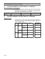
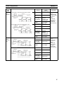
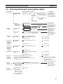
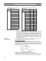
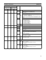
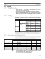
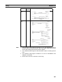
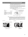
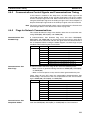
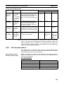
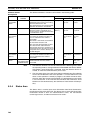
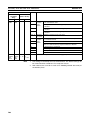
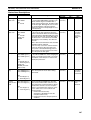
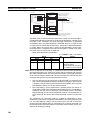
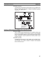
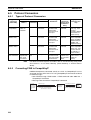
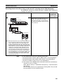
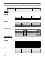
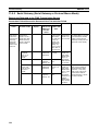
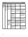
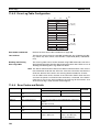
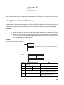
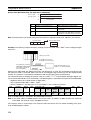
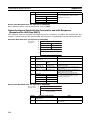
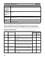
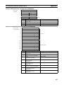
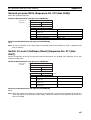
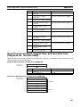
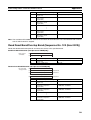
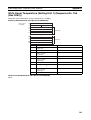
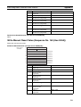
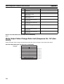
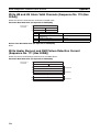
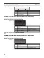
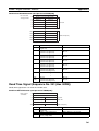
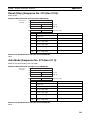
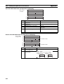
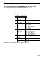
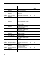
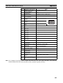
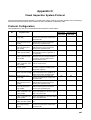
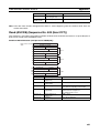
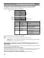
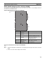
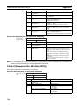
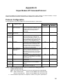
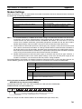
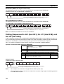
1
Cat. No. W336-E1-09 SYSMAC CS/CJ Series CS1W-SCB@@-V1 Serial Communications Boards CS1W-SCU@@-V1 and CJ1W-SCU@@-V1 Serial Communications Units OPERATION MANUAL SYSMAC CS/CJ Series Serial Communications Boards and Serial Communications Units Operation Manual Revised February 2008 iv Notice: OMRON products are manufactured for use according to proper procedures by a qualified operator and only for the purposes described in this manual. The following conventions are used to indicate and classify precautions in this manual. Always heed the information provided with them. Failure to heed precautions can result in injury to people or damage to property. !DANGER Indicates an imminently hazardous situation which, if not avoided, will result in death or serious injury. Additionally, there may be property damage. !WARNING Indicates a potentially hazardous situation which, if not avoided, could result in death or serious injury. Additionally, there may be property damage. !Caution Indicates a potentially hazardous situation which, if not avoided, may result in minor or moderate injury, or property damage. OMRON Product References All OMRON products are capitalized in this manual. The word “Unit” is also capitalized when it refers to an OMRON product, regardless of whether or not it appears in the proper name of the product. The abbreviation “Ch,” which appears in some displays and on some OMRON products, often means “word” and is abbreviated “Wd” in documentation in this sense. The abbreviation “PLC” means Programmable Controller. “PC” is used, however, in some Programming Device displays to mean Programmable Controller. Visual Aids The following headings appear in the left column of the manual to help you locate different types of information. Note Indicates information of particular interest for efficient and convenient operation of the product. 1,2,3... 1. Indicates lists of one sort or another, such as procedures, checklists, etc. OMRON, 1999 All rights reserved. No part of this publication may be reproduced, stored in a retrieval system, or transmitted, in any form, or by any means, mechanical, electronic, photocopying, recording, or otherwise, without the prior written permission of OMRON. No patent liability is assumed with respect to the use of the information contained herein. Moreover, because OMRON is constantly striving to improve its high-quality products, the information contained in this manual is subject to change without notice. Every precaution has been taken in the preparation of this manual. Nevertheless, OMRON assumes no responsibility for errors or omissions. Neither is any liability assumed for damages resulting from the use of the information contained in this publication. v vi TABLE OF CONTENTS PRECAUTIONS . . . . . . . . . . . . . . . . . . . . . . . . . . . . . . . . . . . xvii 1 Intended Audience . . . . . . . . . . . . . . . . . . . . . . . . . . . . . . . . . . . . . . . . . . . . . . . . . . . . . . . . xviii 2 General Precautions . . . . . . . . . . . . . . . . . . . . . . . . . . . . . . . . . . . . . . . . . . . . . . . . . . . . . . . xviii 3 Safety Precautions. . . . . . . . . . . . . . . . . . . . . . . . . . . . . . . . . . . . . . . . . . . . . . . . . . . . . . . . . xviii 4 Operating Environment Precautions . . . . . . . . . . . . . . . . . . . . . . . . . . . . . . . . . . . . . . . . . . . xix 5 Application Precautions . . . . . . . . . . . . . . . . . . . . . . . . . . . . . . . . . . . . . . . . . . . . . . . . . . . . xx 6 Conformance to EC Directives . . . . . . . . . . . . . . . . . . . . . . . . . . . . . . . . . . . . . . . . . . . . . . . xxii 7 Unit Versions of CS/CJ-series Serial Communications Boards/Units . . . . . . . . . . . . . . . . . xxiv 8 Functions Added in the Unit Version 1.3 Upgrade . . . . . . . . . . . . . . . . . . . . . . . . . . . . . . . . xxviii 9 Functions Added in the Unit Version 1.2 Upgrade . . . . . . . . . . . . . . . . . . . . . . . . . . . . . . . . xxviii SECTION 1 Introduction . . . . . . . . . . . . . . . . . . . . . . . . . . . . . . . . . . . . . . 1 1-1 Using this Manual . . . . . . . . . . . . . . . . . . . . . . . . . . . . . . . . . . . . . . . . . . . . . . . . . . . . . . . . . 2 1-2 Overview . . . . . . . . . . . . . . . . . . . . . . . . . . . . . . . . . . . . . . . . . . . . . . . . . . . . . . . . . . . . . . . . 3 1-3 Protocol Overview. . . . . . . . . . . . . . . . . . . . . . . . . . . . . . . . . . . . . . . . . . . . . . . . . . . . . . . . . 7 1-4 Features . . . . . . . . . . . . . . . . . . . . . . . . . . . . . . . . . . . . . . . . . . . . . . . . . . . . . . . . . . . . . . . . . 12 1-5 System Configurations . . . . . . . . . . . . . . . . . . . . . . . . . . . . . . . . . . . . . . . . . . . . . . . . . . . . . 16 1-6 Specifications . . . . . . . . . . . . . . . . . . . . . . . . . . . . . . . . . . . . . . . . . . . . . . . . . . . . . . . . . . . . 23 1-7 Comparison to Previous Products . . . . . . . . . . . . . . . . . . . . . . . . . . . . . . . . . . . . . . . . . . . . . 35 1-8 Selecting the Serial Communications Mode . . . . . . . . . . . . . . . . . . . . . . . . . . . . . . . . . . . . . 41 1-9 Basic Operating Procedure . . . . . . . . . . . . . . . . . . . . . . . . . . . . . . . . . . . . . . . . . . . . . . . . . . 42 SECTION 2 Initial Settings and I/O Memory Allocations . . . . . . . . . . . . 61 2-1 Component Names and Functions . . . . . . . . . . . . . . . . . . . . . . . . . . . . . . . . . . . . . . . . . . . . 62 2-2 Data Exchange with the CPU Unit . . . . . . . . . . . . . . . . . . . . . . . . . . . . . . . . . . . . . . . . . . . . 72 2-3 I/O Memory Allocations . . . . . . . . . . . . . . . . . . . . . . . . . . . . . . . . . . . . . . . . . . . . . . . . . . . . 74 SECTION 3 Installation and Wiring . . . . . . . . . . . . . . . . . . . . . . . . . . . . . 89 3-1 Installing a Serial Communications Board . . . . . . . . . . . . . . . . . . . . . . . . . . . . . . . . . . . . . . 90 3-2 Installing Serial Communications Units . . . . . . . . . . . . . . . . . . . . . . . . . . . . . . . . . . . . . . . . 91 3-3 Wiring . . . . . . . . . . . . . . . . . . . . . . . . . . . . . . . . . . . . . . . . . . . . . . . . . . . . . . . . . . . . . . . . . . 95 3-4 RS-232C and RS-422A/485 Wiring . . . . . . . . . . . . . . . . . . . . . . . . . . . . . . . . . . . . . . . . . . . 114 SECTION 4 Using Host Link Communications . . . . . . . . . . . . . . . . . . . . 123 4-1 Host Link Communications . . . . . . . . . . . . . . . . . . . . . . . . . . . . . . . . . . . . . . . . . . . . . . . . . 124 4-2 Setup Area Allocations . . . . . . . . . . . . . . . . . . . . . . . . . . . . . . . . . . . . . . . . . . . . . . . . . . . . . 124 4-3 Auxiliary Area and CIO Area Allocations . . . . . . . . . . . . . . . . . . . . . . . . . . . . . . . . . . . . . . 128 4-4 Communications Timing. . . . . . . . . . . . . . . . . . . . . . . . . . . . . . . . . . . . . . . . . . . . . . . . . . . . 132 4-5 Changes from Previous Products . . . . . . . . . . . . . . . . . . . . . . . . . . . . . . . . . . . . . . . . . . . . . 136 4-6 Host Link Function for Replacing Existing PLCs . . . . . . . . . . . . . . . . . . . . . . . . . . . . . . . . 139 vii TABLE OF CONTENTS SECTION 5 Using Protocol Macros . . . . . . . . . . . . . . . . . . . . . . . . . . . . . . 145 5-1 Overview of the Protocol Macro Functions. . . . . . . . . . . . . . . . . . . . . . . . . . . . . . . . . . . . . . 146 5-2 Setup Area Allocations . . . . . . . . . . . . . . . . . . . . . . . . . . . . . . . . . . . . . . . . . . . . . . . . . . . . . 153 5-3 Auxiliary Area and CIO Area Allocations . . . . . . . . . . . . . . . . . . . . . . . . . . . . . . . . . . . . . . 159 5-4 Using Protocol Macros . . . . . . . . . . . . . . . . . . . . . . . . . . . . . . . . . . . . . . . . . . . . . . . . . . . . . 176 5-5 Simple Backup Function (Backup of Protocol Macro Data). . . . . . . . . . . . . . . . . . . . . . . . . 187 5-6 Enhanced Protocol Macro Functions. . . . . . . . . . . . . . . . . . . . . . . . . . . . . . . . . . . . . . . . . . . 190 SECTION 6 Serial Gateway . . . . . . . . . . . . . . . . . . . . . . . . . . . . . . . . . . . . 195 6-1 Serial Gateway Overview . . . . . . . . . . . . . . . . . . . . . . . . . . . . . . . . . . . . . . . . . . . . . . . . . . . 196 6-2 DM Area Allocations (Using Serial Gateway Mode) . . . . . . . . . . . . . . . . . . . . . . . . . . . . . . 201 6-3 Auxiliary Area and CIO Area in Serial Gateway Mode . . . . . . . . . . . . . . . . . . . . . . . . . . . . 204 6-4 Using the Serial Gateway . . . . . . . . . . . . . . . . . . . . . . . . . . . . . . . . . . . . . . . . . . . . . . . . . . . 208 6-5 Protocol Conversion . . . . . . . . . . . . . . . . . . . . . . . . . . . . . . . . . . . . . . . . . . . . . . . . . . . . . . . 212 6-6 Serial Gateway . . . . . . . . . . . . . . . . . . . . . . . . . . . . . . . . . . . . . . . . . . . . . . . . . . . . . . . . . . . . 226 6-7 Conditions Requiring Routing Tables . . . . . . . . . . . . . . . . . . . . . . . . . . . . . . . . . . . . . . . . . . 230 6-8 Communications Frames . . . . . . . . . . . . . . . . . . . . . . . . . . . . . . . . . . . . . . . . . . . . . . . . . . . . 237 SECTION 7 No-protocol Mode . . . . . . . . . . . . . . . . . . . . . . . . . . . . . . . . . . 249 7-1 Overview . . . . . . . . . . . . . . . . . . . . . . . . . . . . . . . . . . . . . . . . . . . . . . . . . . . . . . . . . . . . . . . . 250 7-2 Allocation DM Area for No-protocol Mode . . . . . . . . . . . . . . . . . . . . . . . . . . . . . . . . . . . . . 252 7-3 Auxiliary Area and CIO Area Allocations . . . . . . . . . . . . . . . . . . . . . . . . . . . . . . . . . . . . . . 254 7-4 Basic Operating Procedure in No-protocol Mode . . . . . . . . . . . . . . . . . . . . . . . . . . . . . . . . . 260 SECTION 8 Using 1:N NT Links . . . . . . . . . . . . . . . . . . . . . . . . . . . . . . . . 263 8-1 Overview of 1:N NT Links . . . . . . . . . . . . . . . . . . . . . . . . . . . . . . . . . . . . . . . . . . . . . . . . . . 264 8-2 Setup Area Allocations . . . . . . . . . . . . . . . . . . . . . . . . . . . . . . . . . . . . . . . . . . . . . . . . . . . . . 266 8-3 Auxiliary Area and CIO Area Allocations . . . . . . . . . . . . . . . . . . . . . . . . . . . . . . . . . . . . . . 267 SECTION 9 Using Modbus-RTU Slave Mode (Unit Version 1.3 or Later). . . . . . . . . . . . . . . . . . . . . . . . . . . 273 viii 9-1 Modbus-RTU Slave System. . . . . . . . . . . . . . . . . . . . . . . . . . . . . . . . . . . . . . . . . . . . . . . . . . 274 9-2 Setup Area Allocations (Modbus-RTU Slave Mode) . . . . . . . . . . . . . . . . . . . . . . . . . . . . . . 275 9-3 Auxiliary Area and CIO Area Allocations (Modbus-RTU Slave Mode) . . . . . . . . . . . . . . . 278 9-4 Communications Timing . . . . . . . . . . . . . . . . . . . . . . . . . . . . . . . . . . . . . . . . . . . . . . . . . . . . 290 9-5 Changes from Previous Products. . . . . . . . . . . . . . . . . . . . . . . . . . . . . . . . . . . . . . . . . . . . . . 295 9-6 Modbus-RTU Slave Function for Replacing Existing PLCs . . . . . . . . . . . . . . . . . . . . . . . . . 298 TABLE OF CONTENTS SECTION 10 Loopback Test. . . . . . . . . . . . . . . . . . . . . . . . . . . . . . . . . . . . . 303 10-1 Executing Loopback Tests . . . . . . . . . . . . . . . . . . . . . . . . . . . . . . . . . . . . . . . . . . . . . . . . . . 304 10-2 Setup Area Allocations . . . . . . . . . . . . . . . . . . . . . . . . . . . . . . . . . . . . . . . . . . . . . . . . . . . . . 305 10-3 CIO Area Allocations . . . . . . . . . . . . . . . . . . . . . . . . . . . . . . . . . . . . . . . . . . . . . . . . . . . . . . 306 SECTION 11 Troubleshooting and Maintenance . . . . . . . . . . . . . . . . . . . . 307 11-1 Indicator Error Displays . . . . . . . . . . . . . . . . . . . . . . . . . . . . . . . . . . . . . . . . . . . . . . . . . . . . 308 11-2 Status Area Error Indications . . . . . . . . . . . . . . . . . . . . . . . . . . . . . . . . . . . . . . . . . . . . . . . . 311 11-3 Troubleshooting . . . . . . . . . . . . . . . . . . . . . . . . . . . . . . . . . . . . . . . . . . . . . . . . . . . . . . . . . . 312 11-4 Error Logs . . . . . . . . . . . . . . . . . . . . . . . . . . . . . . . . . . . . . . . . . . . . . . . . . . . . . . . . . . . . . . . 347 11-5 Cleaning and Inspection . . . . . . . . . . . . . . . . . . . . . . . . . . . . . . . . . . . . . . . . . . . . . . . . . . . . 354 11-6 Replacement Precautions . . . . . . . . . . . . . . . . . . . . . . . . . . . . . . . . . . . . . . . . . . . . . . . . . . . 355 Appendices A Introduction . . . . . . . . . . . . . . . . . . . . . . . . . . . . . . . . . . . . . . . . . . . . . . . . . . . . . . . . . . . . . 359 B CompoWay/F Master Protocol . . . . . . . . . . . . . . . . . . . . . . . . . . . . . . . . . . . . . . . . . . . . . . . 363 C C-mode (Host Link) Command Master . . . . . . . . . . . . . . . . . . . . . . . . . . . . . . . . . . . . . . . . 393 D Host Link FINS Command Master . . . . . . . . . . . . . . . . . . . . . . . . . . . . . . . . . . . . . . . . . . . 417 E Mitsubishi Computer Link Master (A-compatible 1C Frame, Model 1) . . . . . . . . . . . . . . . 441 F E5@K Digital Controller Read Protocol . . . . . . . . . . . . . . . . . . . . . . . . . . . . . . . . . . . . . . . 465 G E5@K Digital Controller Write Protocol . . . . . . . . . . . . . . . . . . . . . . . . . . . . . . . . . . . . . . . 485 H E5ZE Temperature Controller Read Protocol . . . . . . . . . . . . . . . . . . . . . . . . . . . . . . . . . . . 501 I E5ZE Temperature Controller Write Protocol . . . . . . . . . . . . . . . . . . . . . . . . . . . . . . . . . . . 523 J E5@J Temperature Controller Protocol . . . . . . . . . . . . . . . . . . . . . . . . . . . . . . . . . . . . . . . . 543 K ES100@ Digital Controller Protocol . . . . . . . . . . . . . . . . . . . . . . . . . . . . . . . . . . . . . . . . . . 559 L K3T@ Intelligent Signal Processor Protocol . . . . . . . . . . . . . . . . . . . . . . . . . . . . . . . . . . . . 599 M V500/V520 Bar Code Reader Protocol . . . . . . . . . . . . . . . . . . . . . . . . . . . . . . . . . . . . . . . . 621 N 3Z4L Laser Micrometer Protocol . . . . . . . . . . . . . . . . . . . . . . . . . . . . . . . . . . . . . . . . . . . . 633 O Visual Inspection System Protocol . . . . . . . . . . . . . . . . . . . . . . . . . . . . . . . . . . . . . . . . . . . 669 P V600/V620 ID Controller Protocol . . . . . . . . . . . . . . . . . . . . . . . . . . . . . . . . . . . . . . . . . . . 689 Q Hayes Modem AT Command Protocol . . . . . . . . . . . . . . . . . . . . . . . . . . . . . . . . . . . . . . . . 727 R Changing Communications Port Settings Using STUP(237) . . . . . . . . . . . . . . . . . . . . . . . 735 Index . . . . . . . . . . . . . . . . . . . . . . . . . . . . . . . . . . . . . . . . . . . . 739 Revision History . . . . . . . . . . . . . . . . . . . . . . . . . . . . . . . . . . . 749 ix x About this Manual: This manual describes the installation and operation of the SYSMAC CS/CJ-series CS1W-SCB@@-V1 Serial Communications Boards and CS1W-SCU@@-V1 and CJ1W-SCU@@-V1 Serial Communications Units and includes the sections described on the next page. The Serial Communications Boards are classified as Inner Boards and the Serial Communications Unit is classified as a CPU Bus Unit. Please read this manual and all related manuals listed in the following table carefully and be sure you understand the information provided before attempting to install and operate a Serial Communications Board or Unit. Name SYSMAC CS/CJ-series CS1W-SCB@@-V1, CS1W-SCU@@-V1, CJ1W-SCU@@-V1 Serial Communications Boards and Serial Communications Unit Operation Manual (this manual) Cat. No. W336 Contents Describes the use of Serial Communications Unit and Boards to perform serial communications with external devices, including the usage of standard system protocols for OMRON products. SYSMAC CS/CJ-series CQM1H-PRO-E1, CQM1-PRO01-E, C200H-PRO27-E Programming Consoles Operation Manual SYSMAC CS-series CS1G/H-CPU@@H, CS1G/HCPU@@-EV1 Programmable Controllers Operation Manual W341 Provides information on how to program and operate CS/CJ-series PLCs using a Programming Console. W339 Describes the installation and operation of the CSseries PLCs. SYSMAC CJ-series CJ1G/H-CPU@@H, CJ1M-CPU@@, CJ1G-CPU@@ Programmable Controllers Operation Manual SYSMAC CS/CJ-series CS1G/H-CPU@@-EV1, CS1G/H-CPU@@H, CJ1G-CPU@@-E, CJ1G/H-CPU@@H Programmable Controllers Programming Manual W393 Describes the installation and operation of the CJseries PLCs. W394 Describes the ladder diagram programming functions and other functions supported by CS-series and CJseries PLCs. SYSMAC CS/CJ-series CS1G/H-CPU@@H, CS1G/ W340 H-CPU@@-EV1, CJ1G/H-CPU@@H, CJ1G-CPU@@, CJ1M-CPU@@ Programmable Controllers Instructions Reference Manual W342 SYSMAC CS/CJ-series CS1G-/H-CPU@@H, CS1G/H-CPU@@-E, CS1WSCB@@-V1, CS1W-SCU@@-V1, CJ1G/H-CPU@@H, CJ1G-CPU@@, CJ1W-CPU@@, CJ1W-SCU@@-V1 Communications Commands Reference Manual SYSMAC WS02-CXPC1-E-V60 CX-Programmer Operation Manual W446 SYSMAC WS02-PSTC1-E CX-Protocol Operation Manual W344 SYSMAC CS/CJ-series CS1W-ETN01, CS1W-ETN11, CJ1W-ETN11 Ethernet Unit Operation Manual W343 Describes the ladder diagram programming instructions supported by CS-series and CJ-series PLCs. Describes the Host Link and FINS communications commands used with CS-series and CJ-series PLCs. Provides information on how to use the CX-Programmer, a programming device that supports the CSseries and CJ-series PLCs. Describes the use of the CX-Protocol to create protocol macros as communications sequences to communicate with external devices. Describes the installation and operation of CS1WETN01, CS1W-ETN11, and CJ1W-ETN11 Ethernet Unit. xi About this Manual, Continued This manual contains the following sections. Section 1 introduces the hardware and software functions of the Serial Communications Boards and the Serial Communications Units, including the communications modes, system configurations, and specifications. Section 2 describes the components of the Serial Communications Boards and the Serial Communications Units, the settings required for operation, and the memory allocated in the I/O memory of the CPU Unit for controlling and monitoring communications. Section 3 describes how to mounting the Serial Communications Boards and Serial Communications Units, and how to connect the ports to external devices. Section 4 describes the procedure and other information required to use Host Link communications. Section 5 describes the procedure and other information required to use protocol macros. Section 6 provides an overview of the Serial Gateway, information on I/O memory allocations, and procedures for using the functions. Information on protocol conversion, routing table requirements, and communications frames is also provided. The Serial Gateway can be used only for Unit Ver. 1.2 or later. Section 7 describes the procedure and other information required to use the no-protocol mode. This mode is supported for Unit Ver. 1.2 or later only. Section 8 describes the procedure and other information required to use 1:N NT Links to Programmable Terminals. Section 9 describes the procedure and other information required to use Modbus-RTU slave mode. Section 10 describes the procedure and other information required to conduct loopback test to check the serial ports. Section 11 describes the troubleshooting and maintenance procedures for the Serial Communications Boards and the Serial Communications Units. Appendix A to Appendix Q provide the specifications of the standard system protocols. Appendix R provides information on using STUP(237) to change serial port settings. !WARNING Failure to read and understand the information provided in this manual may result in personal injury or death, damage to the product, or product failure. Please read each section in its entirety and be sure you understand the information provided in the section and related sections before attempting any of the procedures or operations given. xii Read and Understand this Manual Please read and understand this manual before using the product. Please consult your OMRON representative if you have any questions or comments. Warranty and Limitations of Liability WARRANTY OMRON's exclusive warranty is that the products are free from defects in materials and workmanship for a period of one year (or other period if specified) from date of sale by OMRON. OMRON MAKES NO WARRANTY OR REPRESENTATION, EXPRESS OR IMPLIED, REGARDING NONINFRINGEMENT, MERCHANTABILITY, OR FITNESS FOR PARTICULAR PURPOSE OF THE PRODUCTS. ANY BUYER OR USER ACKNOWLEDGES THAT THE BUYER OR USER ALONE HAS DETERMINED THAT THE PRODUCTS WILL SUITABLY MEET THE REQUIREMENTS OF THEIR INTENDED USE. OMRON DISCLAIMS ALL OTHER WARRANTIES, EXPRESS OR IMPLIED. LIMITATIONS OF LIABILITY OMRON SHALL NOT BE RESPONSIBLE FOR SPECIAL, INDIRECT, OR CONSEQUENTIAL DAMAGES, LOSS OF PROFITS OR COMMERCIAL LOSS IN ANY WAY CONNECTED WITH THE PRODUCTS, WHETHER SUCH CLAIM IS BASED ON CONTRACT, WARRANTY, NEGLIGENCE, OR STRICT LIABILITY. In no event shall the responsibility of OMRON for any act exceed the individual price of the product on which liability is asserted. IN NO EVENT SHALL OMRON BE RESPONSIBLE FOR WARRANTY, REPAIR, OR OTHER CLAIMS REGARDING THE PRODUCTS UNLESS OMRON'S ANALYSIS CONFIRMS THAT THE PRODUCTS WERE PROPERLY HANDLED, STORED, INSTALLED, AND MAINTAINED AND NOT SUBJECT TO CONTAMINATION, ABUSE, MISUSE, OR INAPPROPRIATE MODIFICATION OR REPAIR. xiii Application Considerations SUITABILITY FOR USE OMRON shall not be responsible for conformity with any standards, codes, or regulations that apply to the combination of products in the customer's application or use of the products. At the customer's request, OMRON will provide applicable third party certification documents identifying ratings and limitations of use that apply to the products. This information by itself is not sufficient for a complete determination of the suitability of the products in combination with the end product, machine, system, or other application or use. The following are some examples of applications for which particular attention must be given. This is not intended to be an exhaustive list of all possible uses of the products, nor is it intended to imply that the uses listed may be suitable for the products: • Outdoor use, uses involving potential chemical contamination or electrical interference, or conditions or uses not described in this manual. • Nuclear energy control systems, combustion systems, railroad systems, aviation systems, medical equipment, amusement machines, vehicles, safety equipment, and installations subject to separate industry or government regulations. • Systems, machines, and equipment that could present a risk to life or property. Please know and observe all prohibitions of use applicable to the products. NEVER USE THE PRODUCTS FOR AN APPLICATION INVOLVING SERIOUS RISK TO LIFE OR PROPERTY WITHOUT ENSURING THAT THE SYSTEM AS A WHOLE HAS BEEN DESIGNED TO ADDRESS THE RISKS, AND THAT THE OMRON PRODUCTS ARE PROPERLY RATED AND INSTALLED FOR THE INTENDED USE WITHIN THE OVERALL EQUIPMENT OR SYSTEM. PROGRAMMABLE PRODUCTS OMRON shall not be responsible for the user's programming of a programmable product, or any consequence thereof. xiv Disclaimers CHANGE IN SPECIFICATIONS Product specifications and accessories may be changed at any time based on improvements and other reasons. It is our practice to change model numbers when published ratings or features are changed, or when significant construction changes are made. However, some specifications of the products may be changed without any notice. When in doubt, special model numbers may be assigned to fix or establish key specifications for your application on your request. Please consult with your OMRON representative at any time to confirm actual specifications of purchased products. DIMENSIONS AND WEIGHTS Dimensions and weights are nominal and are not to be used for manufacturing purposes, even when tolerances are shown. PERFORMANCE DATA Performance data given in this manual is provided as a guide for the user in determining suitability and does not constitute a warranty. It may represent the result of OMRON's test conditions, and the users must correlate it to actual application requirements. Actual performance is subject to the OMRON Warranty and Limitations of Liability. ERRORS AND OMISSIONS The information in this manual has been carefully checked and is believed to be accurate; however, no responsibility is assumed for clerical, typographical, or proofreading errors, or omissions. xv xvi PRECAUTIONS This section provides general precautions for using the CS/CJ-series Serial Communications Boards and Units. The information contained in this section is important for the safe and reliable application of Programmable Controllers. You must read this section and understand the information contained before attempting to set up or operate a PLC system. 1 2 3 4 5 6 7 8 9 Intended Audience . . . . . . . . . . . . . . . . . . . . . . . . . . . . . . . . . . . . . . . . . . . . . General Precautions . . . . . . . . . . . . . . . . . . . . . . . . . . . . . . . . . . . . . . . . . . . . Safety Precautions. . . . . . . . . . . . . . . . . . . . . . . . . . . . . . . . . . . . . . . . . . . . . . Operating Environment Precautions . . . . . . . . . . . . . . . . . . . . . . . . . . . . . . . . Application Precautions . . . . . . . . . . . . . . . . . . . . . . . . . . . . . . . . . . . . . . . . . Conformance to EC Directives . . . . . . . . . . . . . . . . . . . . . . . . . . . . . . . . . . . . 6-1 Applicable Directives . . . . . . . . . . . . . . . . . . . . . . . . . . . . . . . . . . . . 6-2 Concepts . . . . . . . . . . . . . . . . . . . . . . . . . . . . . . . . . . . . . . . . . . . . . . 6-3 Conformance to EC Directives . . . . . . . . . . . . . . . . . . . . . . . . . . . . . 6-4 EMI Measures for Serial Communications Boards and Units . . . . . 6-5 EMS Measures for Serial Communications Units . . . . . . . . . . . . . . Unit Versions of CS/CJ-series Serial Communications Boards/Units . . . . . . Functions Added in the Unit Version 1.3 Upgrade . . . . . . . . . . . . . . . . . . . . . Functions Added in the Unit Version 1.2 Upgrade . . . . . . . . . . . . . . . . . . . . . xviii xviii xviii xix xx xxii xxii xxii xxiii xxiii xxiv xxiv xxviii xxviii xvii 1 Intended Audience 1 Intended Audience This manual is intended for the following personnel, who must also have knowledge of electrical systems (an electrical engineer or the equivalent). • Personnel in charge of installing FA systems. • Personnel in charge of designing FA systems. • Personnel in charge of managing FA systems and facilities. 2 General Precautions The user must operate the product according to the performance specifications described in the operation manuals. Before using the product under conditions which are not described in the manual or applying the product to nuclear control systems, railroad systems, aviation systems, vehicles, combustion systems, medical equipment, amusement machines, safety equipment, and other systems, machines, and equipment that may have a serious influence on lives and property if used improperly, consult your OMRON representative. Make sure that the ratings and performance characteristics of the product are sufficient for the systems, machines, and equipment, and be sure to provide the systems, machines, and equipment with double safety mechanisms. This manual provides information for programming and operating the Unit. Be sure to read this manual before attempting to use the Unit and keep this manual close at hand for reference during operation. !WARNING It is extremely important that a PLC and all PLC Units be used for the specified purpose and under the specified conditions, especially in applications that can directly or indirectly affect human life. You must consult with your OMRON representative before applying a PLC System to the above-mentioned applications. 3 Safety Precautions !WARNING Provide safety measures in external circuits (i.e., not in the Programmable Controller), including the following items, to ensure safety in the system if an abnormality occurs due to malfunction of the PLC or another external factor affecting the PLC operation. Not doing so may result in serious accidents. • Emergency stop circuits, interlock circuits, limit circuits, and similar safety measures must be provided in external control circuits. • The PLC will turn OFF all outputs when its self-diagnosis function detects any error or when a severe failure alarm (FALS) instruction is executed. As a countermeasure for such errors, external safety measures must be provided to ensure safety in the system. • The PLC outputs may remain ON or OFF due to deposition or burning of the output relays or destruction of the output transistors. As a countermeasure for such problems, external safety measures must be provided to ensure safety in the system. • When the 24-V DC output (service power supply to the PLC) is overloaded or short-circuited, the voltage may drop and result in the outputs xviii Operating Environment Precautions 4 being turned OFF. As a countermeasure for such problems, external safety measures must be provided to ensure safety in the system. !WARNING Do not attempt to take any Unit apart while the power is being supplied. Doing so may result in electric shock. !WARNING Do not touch any of the terminals or terminal blocks while the power is being supplied. Doing so may result in electric shock. !WARNING Do not attempt to disassemble, repair, or modify any Units. Any attempt to do so may result in malfunction, fire, or electric shock. !Caution Execute online edit only after confirming that no adverse effects will be caused by extending the cycle time. Otherwise, the input signals may not be readable. 4 Operating Environment Precautions !Caution Do not operate the control system in the following places: • Locations subject to direct sunlight. • Locations subject to temperatures or humidity outside the range specified in the specifications. • Locations subject to condensation as the result of severe changes in temperature. • Locations subject to corrosive or flammable gases. • Locations subject to dust (especially iron dust) or salts. • Locations subject to exposure to water, oil, or chemicals. • Locations subject to shock or vibration. !Caution Take appropriate and sufficient countermeasures when installing systems in the following locations: • Locations subject to static electricity or other forms of noise. • Locations subject to strong electromagnetic fields. • Locations subject to possible exposure to radioactivity. • Locations close to power supplies. !Caution The operating environment of the PLC System can have a large effect on the longevity and reliability of the system. Improper operating environments can lead to malfunction, failure, and other unforeseeable problems with the PLC System. Be sure that the operating environment is within the specified conditions at installation and remains within the specified conditions during the life of the system. Follow all installation instructions and precautions provided in the operation manuals. xix 5 Application Precautions 5 Application Precautions Observe the following precautions when using the PLC System. !WARNING Always heed these precautions. Failure to abide by the following precautions could lead to serious or possibly fatal injury. • Always connect to a ground of 100 Ω or less when installing the Units. Not connecting to a ground of 100 Ω or less may result in electric shock. • Always turn OFF the power supply to the PLC before attempting any of the following. Not turning OFF the power supply may result in malfunction or electric shock. • Mounting or dismounting Power Supply Units, I/O Units, CPU Units, Serial Communications Units, or any other Units. • Assembling the Units. • Setting DIP switches or rotary switches. • Connecting cables or wiring the system. • Mounting or dismounting terminal blocks. !Caution Failure to abide by the following precautions could lead to faulty operation of the PLC or the system, or could damage the PLC or PLC Units. Always heed these precautions. • Fail-safe measures must be taken by the customer to ensure safety in the event of incorrect, missing, or abnormal signals caused by broken signal lines, momentary power interruptions, or other causes. • Take appropriate measures to ensure that the specified power with the rated voltage and frequency is supplied. Be particularly careful in places where the power supply is unstable. An incorrect power supply may result in malfunction. • Tighten the mounting screws at the bottom of Serial Communications Units to a torque of 0.4 N⋅m. An incorrect tightening torque may result in malfunction. • Leave the label attached to the Unit when wiring. Removing the label may result in malfunction if foreign matter enters the Unit. • Remove the label after the completion of wiring to ensure proper heat dissipation. Leaving the label attached may result in malfunction. • Always check polarity before wiring RS-422A/485 connectors. The polarity for the SDA/B and RDA/B signals can be different for some external devices. • Check to be sure that terminating resistors have been correctly installed for RS-422A/485 systems before starting operation. • Disconnect the LG terminal of the Power Supply Unit from the GR terminal when performing insulation and dielectric strength tests. • Never turn OFF the power supply while writing protocol macro data. • Wire all connections correctly according to instructions in this manual. • Check terminal blocks completely before mounting them. • Double-check all wiring and switch settings before turning ON the power supply. Incorrect wiring may result in burning. xx 5 Application Precautions • Be sure that the Bus Connection Unit and other items with locking devices are properly locked into place. Improper locking may result in malfunction. • Check the user program for proper execution before actually running it on the Unit. Not checking the program may result in an unexpected operation. • Confirm that no adverse effect will occur in the system before attempting any of the following. Not doing so may result in an unexpected operation. • Changing the operating mode of the PLC (including the setting of the startup operating mode). • Force-setting/force-resetting any bit in memory. • Changing the present value of any word or any set value in memory. • Do not install the product near devices generating strong high-frequency noise. • Do not drop the product or subject it to excessive vibration or shock. • Observe the following precautions for communications cables. • Do not lay communications cables near power lines or high-voltage lines. • Always lay communications cables in ducts. • Do not pull on the communications cables or bend the communications cables beyond their natural limit. Doing either of these may break the cables. • Do not place objects on top of the communications cables or other wiring lines. Doing so may break the cables. • Before touching a Unit, be sure to first touch a grounded metallic object in order to discharge any static built-up. Not doing so may result in malfunction or damage. • Resume operation only after transferring to the new CPU Unit the contents of the DM Area, HR Area, and other data required for resuming operation. Not doing so may result in an unexpected operation. • Do not touch circuit boards or the components mounted to them with your bare hands. There are sharp leads and other parts on the boards that may cause injury if handled improperly. • When transporting or storing Boards, wrap them in material that will protect LSIs, ICs, and other components from static electricity and be sure that they remain within the storage temperature range. • When creating Host Link FINS command frames using the CMND(490) instruction, always set the unit number for Host Link incremented by one (1 to 32) for the remote destination (send destination) node address (word C+3, bits 08 to 15 of the CMND(490) instruction). Do not set the unit number of the actual Host Link slave (0 to 31). Using the Host Link unit number without incrementing by one will access the PLC with the entered Host Link unit number less one. For example, specify the remote PLC with Host Link unit number 2 by entering 3 for the remote destination node address. If 2 is entered, the PLC with Host Link unit number 1 will be accessed. To access a PLC on a Host Link FINS network using the Serial Gateway from CX-Programmer, however, enter the actual Host Link unit number, without incrementing by one. (Select Change PLC, click the Display Serial Gateway Guide Button, and set unit number in the Host Link SYSWAY Settings field of the Serial Gateway Guide Dialog Box. xxi 6 Conformance to EC Directives • When the Serial Gateway is executed during protocol macro execution, the communications sequence contents and the FINS command reception timing may suspend step transition of the communications sequence (when the next step does not contain the RECEIVE command, the Serial Gateway will be executed by interrupting the sequence before the next step, and the step transition will be suspended). Use the Serial Gateway send start timeout function to monitor at the source of the FINS command whether step transition in the communications sequence has been suspended due to execution of the Serial Gateway. If the converted command does not start to be sent within the set time, either retry executing the FINS command or change the communications sequence. • When using 2-wire RS-422A/485 communications in Protocol Macro Mode, set only modem controls for the send control parameters, and do not use RS/CS flow controls. • The following operations will result if the Serial Gateway is executed either using a pre-Ver. 1.2 Board/Unit or using a Ver. 1.2 or later Unit/Board without Serial Gateway or protocol macro mode set for serial communications at the serial port. • If either NT Link or loopback test mode is used for serial communications, or if protocol macro mode is used with a pre-Ver. 1.2 Board/Unit, an undefined command response will be returned (end code: 0401 hex). • If Host Link mode is used for serial communications, the message will be converted into a FINS command using Host Link slave-initiated communications and transferred (this will mainly result in a response timeout being returned, depending on the remote device (end code: 0205 hex)) • If a no-protocol instruction is sent to a pre-Ver. 1.2 Board/Unit or the serial port of a Board/Unit with Unit Ver. 1.2 or later using a serial communications mode other than no-protocol mode, the following operations will occur. • If TXD(236)/RXD(235) is sent to the Board, Auxiliary Area bit A424204 (Inner Board Service Failure Flag) will turn ON. • If TXDU(256)/RXDU(255) is sent to the Unit and the serial communications mode is set to protocol macro, NT Link, loopback test, or Serial Gateway mode, an undefined command error (end code: 0401 hex) will be returned. If the serial communications mode is set to Host Link mode and the instruction will be converted to a slave-initiated function FINS command and transferred. (Depending on the remote device, a response timeout (end code: 0205 hex) is likely to be returned.) 6 6-1 Conformance to EC Directives Applicable Directives • EMC Directives • Low Voltage Directive 6-2 Concepts EMC Directives OMRON devices that comply with EC Directives also conform to the related EMC standards so that they can be more easily built into other devices or the xxii 6 Conformance to EC Directives overall machine. The actual products have been checked for conformity to EMC standards (see the following note). Whether the products conform to the standards in the system used by the customer, however, must be checked by the customer. EMC-related performance of the OMRON devices that comply with EC Directives will vary depending on the configuration, wiring, and other conditions of the equipment or control panel on which the OMRON devices are installed. The customer must, therefore, perform the final check to confirm that devices and the overall machine conform to EMC standards. Note Applicable EMS (Electromagnetic Susceptibility) and EMI (Electromagnetic Interference) standards in the EMC (Electromagnetic Compatibility) standards are as follows: Unit/Board EMS CS1W-SCB21-V1/ SCB41-V1 CS1W-SCU21-V1 EN61131-2 CJ1W-SCU21-V1 CJ1W-SCU31-V1 CJ1W-SCU41-V1 CS1W-SCU31-V1 EN61000-6-2 EMI EN61000-6-4 (Radiated emission: 10-m regulations) Low Voltage Directive Always ensure that devices operating at voltages of 50 to 1,000 VAC and 75 to 1,500 VDC meet the required safety standards for the PLC (EN61131-2). 6-3 Conformance to EC Directives The CS/CJ-series PLCs comply with EC Directives. To ensure that the machine or device in which the CS/CJ-series PLC is used complies with EC directives, the PLC must be installed as follows: 1,2,3... 1. The CS/CJ-series PLC must be installed within a control panel. 2. You must use reinforced insulation or double insulation for the DC power supplies used for the communications power supply and I/O power supplies. 3. CS/CJ-series PLCs complying with EC Directives also conform to the Common Emission Standard (EN61000-6-4). Radiated emission characteristics (10-m regulations) may vary depending on the configuration of the control panel used, other devices connected to the control panel, wiring, and other conditions. You must therefore confirm that the overall machine or equipment complies with EC Directives. 6-4 EMI Measures for Serial Communications Boards and Units The CS/CJ-series PLCs conform to the Common Emission Standards (EN61000-6-4) of the EMC Directives. However, the noise generated from Serial Communications Board or Unit communications cables may not satisfy these standards. In such a case, commercially available ferrite cores must be placed on the communications cable or other appropriate countermeasures must be provided external to the PLC. xxiii Unit Versions of CS/CJ-series Serial Communications Boards/Units 7 Recommended Ferrite Cores The following ferrite core (data line noise filter) is recommended: 0443-164151 by Fair-Rite Products Corp. Low impedance, 25 MHz: 90 Ω, 100 MHz: 160 Ω Recommended Mounting Method Mount the core on one turn of the communications cable, as shown in the following illustration. Mount the cores as lost to the end of the communications cable as possible, as shown in the following illustration. Serial Communications Unit/Board 6-5 EMS Measures for Serial Communications Units The immunity testing conditions for the CJ1W-SCU41-V1 Serial Communications Unit are as follows: A ferrite core is mounted on the test cable connected to the RS-422A/485 port. Refer to 6-4 EMI Measures for Serial Communications Boards and Units for information on mounting the ferrite core. 7 Unit Versions of CS/CJ-series Serial Communications Boards/Units Unit Versions A “unit version” has been introduced to manage CS/CJ-series Serial Communications Units/Boards according to differences in functionality accompanying upgrades. 1. Unit Version Notation on Products The unit version code is provided on the nameplate of the CS-series Serial Communications Boards and Units for which unit versions are being managed, as shown below for the Loop Control Board. This system applies to Serial Communications Units or Boards with unit version 1.2 or later. • Serial Communications Boards xxiv 7 Unit Versions of CS/CJ-series Serial Communications Boards/Units Example: CS1W-SCB21-V1 CS-series Serial Communications Board Nameplate Unit version 1.3 CS1W-SCB21-V1 SERIAL COMMUNICATION BOARD Lot No. 051020 Ver.1.3 OMRON Corporation MADE IN JAPAN • Serial Communications Units Example: CS1W-SCU21-V1 CS-series Nameplate Serial Communications Unit CS1W-SCU21-V1 SERIAL COMMUNICATION UNIT : Unit version 1.3 Lot No. 051020 0000 Ver.1.3 OMRON Corporation MADE IN JAPAN 2. Confirming Unit Versions with Support Software CX-Programmer version 5.0 can be used to confirm the unit version in the Unit Manufacturing Information. ■Boards In the I/O Table Window, right-click on the CPU Unit, and then select Unit Manufacturing Information – Inner Board ■Units 1. In the I/O Table Window, right-click on the Serial Communications Unit, and then select Unit Manufacturing Information. 2. The following Unit Manufacturing Information Dialog Box will be displayed. xxv 7 Unit Versions of CS/CJ-series Serial Communications Boards/Units The unit version is displayed. Example: In this Unit Manufacturing Information Dialog Box, unit version 1.3 is displayed. Use this dialog box to confirm the unit version of the Serial Communications Unit that is connected online. 3. Using the Unit Version Labels Unit version labels are provided with the product. These labels can be attached to the front of previous Serial Communications Boards/Units to differentiate between Serial Communications Boards/Units of different unit versions. Unit Version Notation The unit versions are indicated in this manual as follows: Notation in product Notation in this manual nameplate Ver. 1.3 or later after CS/CJ-series Serial Commuthe lot number nications Units with unit version 1.3 or later xxvi Ver.1.2 after the lot number CS/CJ-series Serial Communications Units with unit version 1.2 Blank after the lot number Pre-Ver. 1.2 CS/CJ-series Serial Communications Units Remarks Information for which no particular version is specified applies to all unit versions. 7 Unit Versions of CS/CJ-series Serial Communications Boards/Units Function Support by Unit Version Product CS Series Serial Communications Boards Earlier version (pre-ver. 1.2) CS1W-SCB21-V1 Unit version 1.3 CS1W-SCB21-V1 (Same as pre-ver. 1.2) CS1W-SCB41-V1 (Same as pre-ver. 1.2) CS1W-SCU21-V1 (Same as pre-ver. 1.2) CS1W-SCB21-V1 (Same as pre-ver. 1.2) CS1W-SCB41-V1 (Same as pre-ver. 1.2) CS1W-SCU21-V1 (Same as pre-ver. 1.2) --CJ1W-SCU21 --CJ1W-SCU21-V1 --- --- CS1W-SCU31-V1 CJ1W-SCU21-V1 (Same as pre-ver. 1.2) CJ1W-SCU31-V1 CJ1W-SCU41 CJ1W-SCU41-V1 CJ1W-SCU41-V1 (Same as pre-ver. 1.2) Serial gateway Not supported Supported Host Link 1:1 links Not supported Supported Host Link compatible device selection No-protocol Not supported Supported Not supported Supported Supported (Same as prever. 1.2) Supported (Same as prever. 1.2) Supported (Same as prever. 1.2) Supported (Same as prever. 1.2) Protocol macro Link word specification data exchange timing Reception buffer processing for PMCR(260) instruction execution On-request I/O refreshing only On-request I/O refreshing On-request I/O refreshing Continuous I/O refreshing Continuous I/O refreshing (Same as pre-ver. 1.2) Select to clear or hold Select to clear or hold concontents. tents. (Same as pre-ver. 1.2) Baud rate (bps) 38,400 max. (57,600 and 57,600 supported. 115,200 not supported) 57,600 supported. (Same as pre-ver. 1.2) Not supported Supported --- --- Supported (Same as prever. 1.2) Supported CS1W-SCB41-V1 Serial Communications Units CJ Series Functions Unit version 1.2 Serial Communications Units Standard system protocol additions MODBUS slave protocol added CS1W-SCU21-V1 Clearing only Note Make sure that a CS/CJ-series CPU Unit with unit version 3.0 or later is used when using no-protocol mode. Unit Versions and Manufacturing Dates/Lot Numbers Classification Type Model May 2004 Inner Boards Serial Communica- CS1W-SCB21-V1 tions Boards CS1W-SCB41-V1 Pre-Ver. 1.2 CPU Bus Units Serial Communica- CS1W-SCU21-V1 tions Units CS1W-SCU21-V1 CS1W-SCU41-V1 Pre-Ver. 1.2 CPU Unit Support Software CX-Programmer June 2003 December 2005 Unit version 1.2 Unit version 1.3 (Lot No.: 040617 and later) Unit version 1.2 Unit version 1.3 (Lot No.: 040617 and later) CS1W-SCU31-V1 CJ1W-SCU31-V1 ----- ----- Unit version 1.3 (Available April, 2006) WS02-CXPC1-JV@ Ver. 4.0 or earlier Ver. 5.0 Version 6.1 xxvii 8 Functions Added in the Unit Version 1.3 Upgrade 8 Functions Added in the Unit Version 1.3 Upgrade Functions Added in Version Upgrade The following table provides a comparison between the functions provided in the upgrade to unit version 1.3 or later of CS1W-SCB@@-V1 Serial Communications Boards and CS1W-SCU@@-V1, CJ1W-SCU@@-V1 Serial Communications Units, and the functionality of earlier versions. Item Serial communications mode 9 Previous unit versions Modbus-RTU slave mode Not supported Unit version 1.3 and later Supported Functions Added in the Unit Version 1.2 Upgrade Upgraded Models The model numbers of CS-series Serial Communications Units/Boards have not changed. A “-V1” suffix has been added to the model numbers of CJseries Serial Communications Units with the unit version 1.2 upgrade, as shown in the following table. PLC CS Series CJ Series xxviii Product Serial Communications Boards Serial Communications Units Serial Communications Units Specifications RS-232C × 1, RS-232C × 1 Model Model number after upgrade to unit version 1.2 CS1W-SCB21-V1 → Same RS-232C × 1, CS1W-SCB41-V1 → RS-422A/485 × 1 Same RS-232C × 1, RS-232C × 1 CS1W-SCU21-V1 → Same RS-232C × 1, RS-232C × 1 CJ1W-SCU21 → CJ1W-SCU21-V1 RS-232C × 1, CJ1W-SCU41 RS-422A/485 × 1 → CJ1W-SCU41-V1 9 Functions Added in the Unit Version 1.2 Upgrade Functions Added in Version Upgrade The following table provides a comparison between the functions provided in the upgrade to unit version 1.2 or later of CS1W-SCB@@-V1 Serial Communications Boards and CS1W-SCU@@-V1, CJ1W-SCU@@-V1 Serial Communications Units, and the functionality of earlier versions. Item Serial communications mode Earlier versions (pre-Ver.1.2) Serial Gateway Host Link No-protocol Unit version 1.2 or later Not supported Supported The received FINS command can be converted into serial communications protocol and then converted into either of the following protocols (using the Serial Gateway mode). • CompoWay/F • Modbus-RTU • Modbus-ASCII • Host Link FINS (This protocol can be used to make the PLC function as the Host Link Master.) The Serial Gateway can also be used in protocol macro mode. This option enables, for example, programming or monitoring of a serially connected PLC from a CX-Programmer that is connected to the PLC during execution of protocol macros (e.g., Host Link Master). 1:1 protocol Not supported (1:N Host Links only) Supported This protocol functions the same as the 1:1 Host Link supported by the earlier C200H, C1000H, and C2000H Series, thereby enabling the use of host computer programs for 1:1 Host LInks created using these earlier PLCs. Note: CS/CJ-series, C200HS/HX/HG/HE(-Z), CPM@, CQM1@, and CVM1/CV Series all support 1:N Host Links only. C200H and C500 Host LInk Units support both 1:1 and 1:N Host Links. Host Link compatible device selection Not supported (not completely compatible with C-series Host Link and CVM1/ CV-series Host Link) The compatible device mode enables full compatibility of Host Link functions (see note) with C-series Host Link and CVM1/CV-series Host Link. Note: E.g., differences in specifications for delimiter words in response frame data Supported, but only when using a CS/CJ-series CPU Unit with unit version 3.0 or later. (The no-protocol mode that was previously possible only at the built-in RS-232C port of CPU Unit is now available for the Serial Communications Boards and Units.) This protocol is mainly used for communications with devices that perform input or output only, such as bar code readers and printers. This mode enables no-protocol communications even if the CPU Unit’s built-in RS-232C port is being used for another application. Not supported xxix 9 Functions Added in the Unit Version 1.2 Upgrade Item Enhanced protocol macro functions Link word specification data exchange timing Reception buffer processing for PMCR(260) instruction execution (immediately before communications sequence execution) Baud rate for protocol macro mode Earlier versions (pre-Ver.1.2) On-request I/O refreshing only (request to refresh sent to CPU Unit at every send/receive command execution, and data exchanged during I/O refresh) In this method, after the send command is executed, a delay occurs before the actual message is sent. Clearing to zero only 38,400 bps max. (57,600 bps not supported) Unit version 1.2 or later Continuous I/O refreshing (selected in DM Area settings) is supported in addition to the on-request I/O refreshing available in earlier models. Continuous I/O refreshing is performed from the CPU Unit during protocol macro execution, regardless of requests from the Board/Unit, and data in the Board/Unit is accessed during send/receive command execution. When the send command is executed with this method, the actual message can be sent immediately. Select to clear or hold the contents of the reception buffer during full-duplex communications (set in the allocation DM Area). This enables the data in the reception buffer received in the previous communications sequence to be held after switching the communications sequence during full-duplex communications. 57,600 bps supported (115,200 bps not supported) Standard sys- Host Link C-mode Command None (protocols must Provided tem protocol Master be created using CX- A Host Link Master can Protocol) be used to easily access the Host Link slave PLC (e.g., A PLC slave on a Host Link FINS Command moving body can be Master accessed via a WMseries Wireless Modem in a Host Link.) Mitsubishi Computer Link Master (A-compatible, 1C frame, model 1) CompoWay/F Master xxx Host Link C-mode commands can be used to access a C-series or CS/ CJ-series PLC slave. Host Link FINS commands can be used to access a CS/CJ-series or CVM1/CV-series PLC slave. This protocol can also be used to access slave PLCs on the network. Provided Computer Link commands can be used to access a Mitsubishi PLC (Sequencer CPU Module) slave. --- Communications sequences with different send and receive protocols are provided by using send/ receive commands with ASCII conversion. The communications sequences have been expanded to include CompoWay/F commands such as VARIABLE AREA READ/WRITE and OPERATING INSTRUCTIONS. SECTION 1 Introduction This section introduces the hardware and software functions of the Serial Communications Boards and the Serial Communications Units, including the communications modes, system configurations, and specifications. 1-1 1-2 1-3 1-4 Using this Manual . . . . . . . . . . . . . . . . . . . . . . . . . . . . . . . . . . . . . . . . . . . . . . 2 Overview . . . . . . . . . . . . . . . . . . . . . . . . . . . . . . . . . . . . . . . . . . . . . . . . . . . . . 3 1-2-1 Serial Communications Boards . . . . . . . . . . . . . . . . . . . . . . . . . . . . 3 1-2-2 Serial Communications Units . . . . . . . . . . . . . . . . . . . . . . . . . . . . . . 4 Protocol Overview. . . . . . . . . . . . . . . . . . . . . . . . . . . . . . . . . . . . . . . . . . . . . . 7 1-3-1 Host Link Mode . . . . . . . . . . . . . . . . . . . . . . . . . . . . . . . . . . . . . . . . 8 1-3-2 Protocol Macros . . . . . . . . . . . . . . . . . . . . . . . . . . . . . . . . . . . . . . . . 9 1-3-3 1:N NT Links . . . . . . . . . . . . . . . . . . . . . . . . . . . . . . . . . . . . . . . . . . 10 1-3-4 Loopback Test. . . . . . . . . . . . . . . . . . . . . . . . . . . . . . . . . . . . . . . . . . 11 1-3-5 Serial Gateway Mode . . . . . . . . . . . . . . . . . . . . . . . . . . . . . . . . . . . . 11 1-3-6 No-protocol Mode . . . . . . . . . . . . . . . . . . . . . . . . . . . . . . . . . . . . . . 11 1-3-7 Modbus-RTU Slave Mode . . . . . . . . . . . . . . . . . . . . . . . . . . . . . . . . 12 Features . . . . . . . . . . . . . . . . . . . . . . . . . . . . . . . . . . . . . . . . . . . . . . . . . . . . . . 12 1-4-1 Serial Communications Boards and Units . . . . . . . . . . . . . . . . . . . . 12 1-4-2 Protocols . . . . . . . . . . . . . . . . . . . . . . . . . . . . . . . . . . . . . . . . . . . . . . 12 1-5 System Configurations . . . . . . . . . . . . . . . . . . . . . . . . . . . . . . . . . . . . . . . . . . 16 1-6 Specifications . . . . . . . . . . . . . . . . . . . . . . . . . . . . . . . . . . . . . . . . . . . . . . . . . 23 1-6-1 Serial Communications Boards and Unit . . . . . . . . . . . . . . . . . . . . . 23 1-6-2 General Specifications . . . . . . . . . . . . . . . . . . . . . . . . . . . . . . . . . . . 25 1-6-3 Protocol Specifications . . . . . . . . . . . . . . . . . . . . . . . . . . . . . . . . . . . 26 1-7 Comparison to Previous Products . . . . . . . . . . . . . . . . . . . . . . . . . . . . . . . . . . 35 1-8 Selecting the Serial Communications Mode . . . . . . . . . . . . . . . . . . . . . . . . . . 41 1-9 Basic Operating Procedure . . . . . . . . . . . . . . . . . . . . . . . . . . . . . . . . . . . . . . . 42 1-9-1 Overview. . . . . . . . . . . . . . . . . . . . . . . . . . . . . . . . . . . . . . . . . . . . . . 42 1-9-2 Explanation of Procedure . . . . . . . . . . . . . . . . . . . . . . . . . . . . . . . . . 43 1 Section 1-1 Using this Manual 1-1 Using this Manual This manual is structured to provide information on Host Link, protocol macro, and 1:N NT link communications in functional units, as would be required in actual applications. You should read Section 1 Introduction first, and then read information in the rest of the manual and related manuals as required by your specific application. Information Overview and appearance of the Serial Communications Boards and Serial Communications Unit Overview, features, and specifications of serial communications Basic procedures and operations Section or Manual 1-2 Overview 2-1 Component Names and Functions 1-3 Protocol Overview 1-4 Features 1-6 Specifications 4-1 Host Link Communications 5-1 Overview of the Protocol Macro Functions 8-1 Overview of 1:N NT Links 1-9 Basic Operating Procedure Selecting serial communications modes System configurations for serial communications modes Memory Area allocations to the Serial Communications Boards and Serial Communications Unit 1-8 Selecting the Serial Communications Mode 1-5 System Configurations Installing and wiring the Serial Communications Boards and Serial Communications Unit Section 3 Installation and Wiring Memory Area allocations to individual serial communications modes 4-2, 5-2, and 8-2 Setup Area Allocations 4-3, 5-3, and 8-3 Auxiliary Area and CIO Area Allocations 2-2 Data Exchange with the CPU Unit 2-3 I/O Memory Allocations Communications timing for slave-initiated Host Link 4-4 Communications Timing communications Ladder diagram programming in protocol macros Loopback tests for ports 5-4 Using Protocol Macros Section 10 Loopback Test Changing the communications port settings during Appendix R Changing Communications Port operation Settings Using STUP(237) Troubleshooting and maintenance The contents of standard system protocols and connection methods to OMRON components Section 11 Troubleshooting and Maintenance Appendix A to Appendix N Details on Host Link communications (including ladder diagram programming for slave-initiated communications) Details on C-mode commands SYSMAC CS/CJ-series CS1G/H-CPU@@-E, CS1W-SCB21/41, CS1W-SCU21 Communications Commands Reference Manual (W342) Details on FINS commands Details on the protocol macro function 2 SYSMAC WS02-PSTC1-E CX-Protocol Operation Manual (W344) Section 1-2 Overview 1-2 Overview This section gives an overview of the Serial Communications Boards and the Serial Communications Unit. 1-2-1 Serial Communications Boards Serial Communications Boards are Inner Boards for the CS-series PLCs. One Board can be installed in the Inner Board slot of a CPU Unit. Two serial ports are provided for connecting host computers, Programmable Terminals (PTs), general-purpose external devices, and Programming Devices (excluding Programming Consoles). This makes it possible to easily increase the number of serial ports for a CS-series PLC. Serial Communications Board Models Inner Board slot The following two models are available: CS1W-SCB21-V1 Two RS-232C ports Connectable Devices General-purpose external device CS1W-SCB41-V1 One RS-232C port + one RS-422A/485 port RS-232C port RS-232C port RS-232C port RS-422A/485 port The following serial communications modes are supported by the Serial Communications Unit: Host Link (SYSMAC WAY) (see note 1), protocol macro, 1:N NT Link (see note 2), no-protocol (see note 1), Modbus-RTU slave (see note 3), and loopback test modes. The devices shown in the following diagram can be connected. Programmable Terminal (PT) Programming Device (excluding Programming Console) Host computer Serial Communications Board CPU Unit General-purpose external device Programmable Terminal (PT) Programming Device (excluding Programming Console) Host computer 3 Section 1-2 Overview Note (1) The Host Link 1:1 and no-protocol modes are supported by unit version 1.2 or later. (2) Only a 1:N NT Link is supported. A 1:1 NT Link is not supported. (3) The Modbus-RTU slave mode is supported by unit version 1.3 or later. A serial communications mode for the Serial Gateway is also provided, enabling connection with the following devices. CompoWay/Fcompatible OMRON component Modbus-RTU-compatible device (e.g., Inverter) Modbus-ASCII-compatible device (e.g., Servo) PLC (Host Link) FINS message Serial Communications Board with unit version 1.2 or later CPU Unit Protocol conversion FINS message Protocol conversion CompoWay/Fcompatible OMRON component PLC (Host Link) Modbus-RTU-compatible device (e.g., Inverter) Modbus-ASCII-compatible device (e.g., Servo) 1-2-2 Serial Communications Units The Serial Communications Units are CPU Bus Unit. One or more Units can be mounted to the CPU Unit or a CS/CJ Expansion Rack. A total of up to 16 CPU Bus Units can be controlled by one CPU Unit. The CS-series Serial Communications Unit must be used for a CS-series PLC and a CJ-series Serial Communications Unit must be used for a CJ-series PLC. Two serial ports are provided for connecting host computers, Programmable Terminals (PTs), general-purpose external devices, and Programming Devices (excluding Programming Console). This makes it possible to easily increase the number of serial ports for the CS/CJ-series PLC. CS Series Serial Communications Unit 4 Section 1-2 Overview CS1W-SCU21-V1 (Two RS-232C ports) CS1W-SCU31-V1 (Two RS-422A/485 ports) RS-232C port RS-422A/485 port RS-232C port RS-422A/485 port CJ Series Serial Communications Unit PA205R SYSMAC CJ1G-CPU44 POWER PROGRAMMABLE CONTROLLER RUN ERR/ALM INH PRPHL SCU41 RUN ERC RDY ERH SD1 RD1 SD2 RD2 TERM OFF ON 01 EF 2 UNIT NO. BCD MCPWR BUSY 789A 3456 WIRE 2 L1 TER1 COMM OPEN 4 PORT1 (RS422 /485) AC100-240V INPUT L2/N PERIPHERAL PORT2 RUN OUTPUT AC240V DC24V PORT CJ1W-SCU21-V1 (Two RS-232C ports) CJ1W-SCU41-V1 (One RS-232C and One RS422A/485 Port) RS-232C port RS-422A/485 port RS-232C port RS-232C port CJ1W-SCU31-V1 (Two RS-422A/485 ports) RS-422A/485 port RS-422A/485 port Connectable Devices The following serial communications modes are supported by the Serial Communications Boards: Host Link (SYSMAC WAY) (see note 1), protocol macro, 1:N NT Link (see note 2), no-protocol (see note 1), Modbus-RTU slave (see note 3), and loopback test modes. The devices shown in the following diagram can be connected. 5 Section 1-2 Overview General-purpose external device Programming Device (excluding Programming Host computer Console) Programmable Terminal (PT) Serial Communications Unit CS/CJ-series PLC General-purpose external device Note Programming Device (excluding Programming Console) Programmable Terminal (PT) Host computer (1) The Host Link 1:1 and no-protocol modes are supported by unit version 1.2 or later. (2) Only a 1:N NT Link is supported. A 1:1 NT Link is not supported. (3) The Modbus-RTU slave mode is supported by unit version 1.3 or later. A serial communications mode for the Serial Gateway is also provided, enabling connection with the following devices. Modbus-RTU-compatible device (e.g., Inverter) Modbus-ASCII-compatible device (e.g., Servo) PLC (Host Link) CompoWay/Fcompatible OMRON component FINS message Serial Communications Unit with unit version 1.2 or later Protocol conversion CPU Unit FINS message Protocol conversion CompoWay/Fcompatible OMRON component PLC (Host Link) Modbus-RTU-compatible device (e.g., Inverter) Modbus-ASCII-compatible device (e.g., Servo) Functions Added in the “-V1” Upgrade The CS1W-SCB21-V1 and CS1W-SCB41-V1 Serial Communications Boards and CS1W-SCU21-V1 Serial Communications Unit* were upgraded to support the Simple Backup Function in the “-V1” upgrade. Simple Backup Function The CPU Unit’s Simple Backup Function can be used to automatically backup, restore, and compare the Protocol Macro data (both standard system protocol and user-set protocol data) in the Serial Communications Board or Unit’s flash memory with the data in the CPU Unit’s Memory Card. The Protocol Macro data is backed up, restored, or compared along with all of the data in the CPU Unit. (The Simple Backup Function can be used with CS1-H, CJ1H, and CJ1M CPU Units only.) 6 Section 1-3 Protocol Overview Note 1-3 *The CS-series Serial Communications Boards/Units without the “-V1” suffix do not support this Simple Backup Function, but the CJ1W-SCU21/41 does support this function even though the model number lacks the “-V1” suffix. Protocol Overview A Serial Communications Board is an Inner Board for CS-series CPU Units that provides RS-232C and/or RS-422A/485 serial ports. An Inner Board is an option and is installed in the CPU Unit. A Serial Communications Unit is a CPU Bus Unit that provides two RS-232C serial ports or one RS-232C and one RS-422A/485 port. The following eight serial communications modes can be used as required for each serial port. • Host Link: For connections between host computers and PLCs • Protocol macro: For communications between PLCs and general-purpose external devices • 1:N NT Link: For communications between PLCs and Programmable Terminals (PTs) • Loopback test: For testing the communications ports • Serial Gateway • No-protocol • 1:1 Host Link • Modbus-RTU slave mode Note (1) The Serial Gateway can also be executed in protocol macro mode. (2) Modbus-ASCII mode is not supported. PLC Series CS CJ Product Serial Communications Boards Model number Serial communications mode Host Link Protocol macro 1:N NT Link (See note 2.) Loopback test Serial Gateway Serial Gateway in protocol macro mode Noprotocol (See note 3.) 1:1 Host Link ModbusRTU slave CS1WSCB21-V1 RS-232C OK OK OK OK OK OK OK OK OK RS-232C OK OK OK OK OK OK OK OK OK CS1WSCB41-V1 RS-232C OK OK OK OK OK OK OK OK OK RS-422A/485 OK (See note 1.) OK OK OK OK OK OK OK OK Serial CS1WCommuniSCU21-V1 cations Unit CS1WSCU31-V1 RS-232C OK OK OK OK OK OK OK OK OK RS-232C OK Serial CJ1WCommuniSCU21-V1 cations Unit CJ1WSCU31-V1 CJ1WSCU41-V1 --- Serial ports OK OK OK OK OK OK OK OK RS-422A/485 OK (See note 1.) OK OK OK OK OK OK OK OK RS-422A/485 OK (See note 1.) OK OK OK OK OK OK OK OK RS-232C OK OK OK OK OK OK OK OK OK RS-232C OK OK OK OK OK OK OK OK OK RS-422A/485 OK (See note 1.) OK OK OK OK OK OK OK OK RS-422A/485 OK (See note 1.) OK OK OK OK OK OK OK OK RS-422A/485 OK (See note 1.) OK OK OK OK OK OK OK OK RS-232C OK OK OK OK Generalpurpose external device Host Link computer Device to be connected Supporting unit versions OK OK OK OK OK Host computer or Programming Device Generalpurpose external device PT None Depends on the protocol used at the conversion destination All unit versions Note Unit version 1.2 or later Unit version 1.3 or later 1. A 4-wire connection must be used when using Host Link communications for an RS-422A/485 connector. 7 Section 1-3 Protocol Overview 2. A 1:1 NT Link is not supported. 3. No-protocol mode can be used with CS/CJ-series CPU Units with Unit Ver. 3.0 or later only. A connection example for each serial communications mode is shown in the following sections for a Serial Communications Unit. The examples apply equally as well to the Serial Communications Boards. 1-3-1 Host Link Mode In Host Link mode, C-mode commands (Host Link commands) or FINS commands can be sent from a host computer to read or write I/O memory in the PLC or to control the PLC’s operating modes. The host computer can be a personal computer or a Programmable Terminal. The FINS commands are sent with other data, such a Host Link header and terminator. In Host Link mode, SEND(090), RECV(098), and CMND(490) instructions can be used to send FINS commands from PLC to the host computer to read data, write data, or perform other operations. This is called slave-initiated communications or unsolicited communications. The FINS commands are sent with other data, such a Host Link header and terminator. Note 1. FINS commands can be sent across up to three different networks (counting the local network) to a PLC on a remote network or to a host computer connected to a PLC on a remote network. 2. Programming Devices can also be connected in Host Link mode. Sending C-mode Commands Host Link C-mode (Host Link) command Sending FINS Commands FINS commands can also be sent to PLCs on remote networks. FINS command Host Link FINS command Host Link FINS command Host Link terminator Host Link header 8 Host Link terminator Host Link header Remote network (Controller Link or Ethernet) Section 1-3 Protocol Overview Slave-initiated Communications SEND(090), RECV(098), CMND(490) SEND(090): Sends data to host computer RECV(098): Reads data from host computer CMND(490): Executes any FINS command Host Link FINS command Host Link terminator Host Link header Slave-initiated FINS commands can also be sent from PLCs on remote networks. SEND(090), RECV(098), CMND(490) Host Link Remote network (Controller Link or Ethernet) FINS command Host Link terminator FINS command Host Link header Unit Ver. 1.2 or later supports the 1:1 Host Link protocol for C200H, C1000H, and C2000H CPU Units, which enables the use of host programs for 1:1 Host Links created for these PLCs. A Host Link-compatible device selection function is also provided for complete compatibility with the C-series Host Link and CVM1/CV-series Host Link. 1-3-2 Protocol Macros Data transfer procedures (protocols) with general-purpose external devices are created using the CX-Protocol to match the communications specifications (half-duplex or full-duplex, and start-stop synchronization) of the external device. These protocols are stored in the Serial Communications Boards or the Serial Communications Unit, and enable data to be exchanged with general-purpose external devices simply by executing the PMCR(260) instruction in the CPU Unit. Standard system protocols for exchanging data with OMRON devices (such as Temperature Controllers, Intelligent Signal Processors, Bar Code Readers, and Modems) are provided as a standard feature in the Serial Communications Boards, the Serial Communications Unit, and the CX-Protocol. The CXProtocol can also be used to change the standard system protocols according to user requirements. PMCR(260) Serial Communications Unit Communications sequence Protocol General-purpose external device 9 Section 1-3 Protocol Overview The following additional functions are supported for unit Ver. 1.2 or later. • Serial Gateway can be executed during protocol macro execution. • An new I/O refresh method is provided for constant data conversion of link words. • The contents of the reception buffer can be held while the PMCR(260) instruction is executing. • A baud rate of 57,600 bps is possible (115,200 bps is not possible). 1-3-3 1:N NT Links A PLC can be connected to one or more Programmable Terminals (PTs) using an RS-232C or RS-422A/485 port. The I/O memory of the PLC is allocated to the Status Control Areas and the Status Notification Areas used by the PTs, as well as to display objects, such as touch switches, lamps, and memory tables. This enables the status of the I/O memory in the PLC to be controlled and monitored by operations from the PTs, without the use of a ladder diagram programming in the PLC. Up to eight PTs can be connected to a PLC. Note The user does not need to be aware of NT Link commands. The user only has to allocate the PLC memory to the PTs. Serial Communications Unit Serial Communications Unit NT Link (Set to 1:N) PT Note 1:N NT Link PT 1. The serial port on the PT must be set to a 1:N NT Link. 2. The Serial Communications Boards and Units do not support 1:1 NT Links. The NT Link must be set to 1:N even if only one PT is connected. Connection is not possible to PTs that do not support 1:N NT Links. 3. The NT20S, NT600S, NT30, NT30C, NT620, NT620C, and NT625C cannot be used if the cycle time of the CPU Unit is 800 ms or longer (even if only one of these PTs is used in a 1:N NT Link). 4. The Programming Console functions of the PT (Expansion Mode) cannot be used when connected to Serial Communications Board or Unit ports. They can be used only by connecting to the peripheral port or RS-232C port on the CPU Unit. 5. Set a unique unit number for each PT connected to the same PLC. If the same unit number is set for more than one PT, malfunctions will occur. 6. NT Link serial communications are unique and are not compatible with other serial communications modes. 10 Section 1-3 Protocol Overview 1-3-4 Loopback Test A connector with a loopback connection is attached to the specified serial port to perform loopback tests. Data is sent to this port, and the communications circuit is tested by comparing the transmitted data and the data returned by loopback. Note This loopback test is performed inside the specified serial port. It is not a loopback test using the RS-232C or RS-422A/485 communications path. Loopback test switch Loopback test The loopback test results are stored. 1-3-5 Serial Gateway Mode The received FINS message is automatically converted to either CompoWay/F, Modbus-RTU, Modbus-ASCII, or Host Link FINS, depending on the type of message. CompoWay/F, Modbus-RTU, and Modbus-ASCII FINS CompoWay/F (See note.) Network Send FINS command Serial Communications Unit Serial Gateway CMND FINS CompoWay/F (See note.) Note: Or Modbus-RTU commands or Modbus ASCII commands CompoWay-compatible OMRON component, Modbus-RTU-, or Modbus ASCII-compatible device CompoWay (See note.) FINS Host Link FINS Network CMND Serial Gateway Send FINS command CX-Programmer or other Programming Device for using CX-Server as a communications driver FINS FINS Host Link header FINS Host Link header Host link terminator Host link terminator PLC (Host Link) 1-3-6 No-protocol Mode No-protocol mode supports data receiving or data sending using data receive or send commands, respectively (see note). No-protocol mode, however, can be used only with CS/CJ-series CPU Units with unit Ver. 3.0 or later in which a Serial Communications Board or Unit with Unit Ver. 1.2 or later is installed. Use the no-protocol mode when the data send and receive protocols are to be created by the user, or when connecting to devices that only receive or send data, such as bar code readers, or printers. 11 Section 1-4 Features Note Serial Communications Boards send/receive data using TXD(236)/RXD(235) instructions. Serial Communications Units send/receive data using TXDU(256)/RXDU(255) instructions. E.g., Execute data transmission E.g., TXDU Serial Communications Unit ST Text CR+LF No-protocol Note: Start code and end code can be specified. General-purpose external device 1-3-7 Modbus-RTU Slave Mode Modbus-RTU slave mode enables sending Modbus-RTU commands from the host computer to read and write PLC I/O memory. Serial Communications Unit Modbus-RTU Modbus command 1-4 Features This section describes the features of the Serial Communications Boards, the Serial Communications Unit, and the protocols. 1-4-1 Serial Communications Boards and Units Serial Communications Boards (CS Series Only) A Serial Communications Board is installed as an option in a CPU Unit. Two serial ports can thus be added without using an I/O slot. There are two types of Serial Communications Boards: One with two RS232C ports and one with one RS-232C and one RS-422A/485 port. The RS422A/485 port can be used for a 1:N connection with general-purpose external devices without using Link Adapters to support the protocol macro function or NT Link function. Serial Communications Unit (CS/CJ Series) 1-4-2 A total of up to 16 CPU Bus Units can be mounted on the CPU Rack or an Expansion Rack. The total of 16 must include all Serial Communications Units and all other CPU Bus Units. The PLC can thus be expanded to provide additional serial ports as required by the system. Protocols Host Link Communications Host Link communications are supported by all CS/CJ-series CPU Units. Serial Communications Boards and Units can be used to connect a single PLC to more than one host computer for Host Link communications, including slave-initiated communications. Host Link communications provide the following features. Connect One Computer to Multiple PLCs 12 An RS-422A/485 port can be used to connect one host computer to up to 32 CS/CJ-series PLCs. Section 1-4 Features Computer Monitoring and Control of PLCs Host Link communications enable the host computer to monitor or control PLC operations and to read and write I/O memory in the PLCs. FINS Commands for Complete Control In addition to C-series (Host Link) commands, FINS commands are also supported. FINS commands give you the power to control CS/CJ-series PLC functionality. Redundant Error Checking Both vertical and horizontal (FCS) parity checks are performed on communications data to achieve essentially error-free communications. Combining error checking and retry processing goes one step further to eliminate nearly all the effects of communications problems. Simultaneous Usage of Both Ports Each Serial Communications Board and Unit provides two serial ports that can be used simultaneously to connect to two different host computers. A total of up to 16 CPU Bus Units, including the Serial Communications Units, can be mounted to one PLC. If all 16 CPU Bus Units are Serial Communications Units, then up to 32 ports can be added. Slave-initiated Communications Communications can be performed either by sending a command from a host computer and having the PLC return a response, or by sending a command from a PLC and having the computer send a response. Starting communications from a slave is called unsolicited communications, and is made possible through the SEND(090), RECV(098), and CMND(490) instructions. These can be used to send FINS commands to a host computer connected locally or to a host computer connected to a remote network up to three networks away (counting the local network). Send FINS Commands to Remote Networks A FINS command contained within a Host Link header and terminator can be sent using Host Link communications to PLCs connected not only on Host Link networks, but also other interconnected remote networks up to three networks away (counting the local network). Various types of networks can exist between the source of the command and the destination of the command. Host Link Bridge Ethernet Network Controller Link Network Controller Link Network Gateway Send FINS Commands to Computers Connected to Remote PLCs A FINS command contained within a Host Link header and terminator can be sent using Host Link communications to a host computer connected to a PLC on a remote network up to three networks away (counting the local network, but not counting the final Host Link connection). Various types of networks can exist between the PLC sending the command and the destination of the command. 13 Section 1-4 Features Bridge Host Link Ethernet Network SEND(090), RECV(098), CMND(490) Controller Link Network Controller Link Network Gateway Protocol Macros The main features of the protocol macro functions are described below. For details, refer to the CX-Protocol Operation Manual (W344). Wide Range of Communications Protocols Communications are possible with virtually any general-purpose external device, provided it has an RS-232C or RS-422A/485 port, supports halfduplex or full-duplex communications, and supports start-stop synchronization. Send Frames and Receive Frames Matching Specifications Send frames (command + data and other send frames) and receive frames (response and other frames) can be created and registered according to the communications frame specifications of the external device. Communications-related Functions Error check code calculations, frame length calculations during sending, and ASCII⇔Hexadecimal conversion of numeric data are supported. Send/Receive Monitoring Receive wait monitoring, receive completion monitoring, and send completion monitoring are supported. If monitoring times are exceeded, send/receive can either be terminated, or retry processing can be performed. Retry Processing Send/receive retry processing can be automatically executed when an error occurs, simply by setting the number of retries. PLC Read/Write Variables in Send Frames and Receive Frames Variables for reading PLC memory can be included in the actual send frames. These can be used as destination addresses or data when reading PLC data while sending. Variables for writing to PLC memory can be also included in the actual receive frames. These can be used to write the contents of destination addresses or data to the PLC during reception. Switch 1:N Communications or the Data Write Destinations Using Repeat Processing Repeat processing (repeat counters) for send/receive processing can be specified in communications sequences. This enables the same data to be sent by switching destination addresses during communications 1:N (N = 32 max. due to restrictions in the physical layer) or by switching the PLC memory write destination addresses during data reception. PLC Interrupts During Data Reception An interrupt can be created in the PLC’s CPU Unit during data reception, and an interrupt program can be executed in the CPU Unit. (The PLC interrupt function is supported only for the Serial Communications Boards. This function cannot be used with Serial Communications Units.) Next Process Switching According to Receive Data The contents of up to 15 set of expected receive data can be compared with the receive data to determine the next process. New Error Check Codes LRC2 (two’s complement of LRC), and SUM1 (one’s complement of SUM) have been added to the error check codes. Step Queuing for Sync Signal from the PLC At any step of the communications sequence, the next process can be made to wait until a sync signal from the PLC’s CPU Unit has been input. This enables processing, such as data manipulations, to be performed in the CPU Unit during the communications sequence. Half-duplex or Full-duplex Transmissions With the conventional protocol macro functions, only half-duplex transmissions were possible. With half-duplex mode, the reception buffer is cleared 14 Section 1-4 Features immediately after the send operation is completed. Therefore, if there was a rapid response from the remote device, for example, the data received between data sending and the completion of the send operation could not be accessed as receive data by the next receive operation. Support for the full-duplex transmissions enables all the data received in a sequence to be accessed. Data can also be received from a remote device while sending. Note Full-duplex transmissions can be used with either RS-232C or RS-422A/485 as long as 1:1, 4-wire connections are used. Full-duplex transmissions cannot be used with 1:N connections or 2-wire connections. Clear Reception Buffer at Any Time With full-duplex mode, the reception buffer is cleared only immediately before a communications sequence is executed. When a reception or other fault occurs, the receive data can be cleared at any time using the reception buffer clear (FLUSH) command. Control ER Signal at Any Time With a connection to a modem, the ER signal is used to show the communications enabled status of a Serial Communications Board or Unit (Data Terminal Equipment (DTE)). In conventional operations, the ER signal could be turned ON only while a communications sequence was being executed. Improving this function has enabled the ER signal to be turned ON or OFF at any time during a communications sequence. This enables modem connections and disconnections to be performed by a protocol macro. The ER signal can also be kept ON, even after a communications sequence has been completed. In this case, the ER signal remains ON, even after it has been switched to a different serial communications mode (for example, Host Link). This function enables remote programming and monitoring to be performed using remote Programming Devices, by switching to the Host Link mode with the STUP(237) instruction once the connection has been made with the modem. 15 Section 1-5 System Configurations 1-5 System Configurations This section explains the system configuration supported by each serial communications mode. Host Link Communications PLC: Computer 1:1 Port: RS-232C Connection configuration Connection to Serial Communications Board. Note 1. Note 3. Note 2. Note 3. NT-AL001-E CS1W-SCB21- Port 1 or 2 V1 CS1W-SCB41V1 NT-AL001-E Converting Link Adapter Port 1 5-V power supply For NT-AL001-E Link Adapter CS1W-SCU21V1 CJ1W-SCU21V1 CJ1W-SCU41V1 NT-AL001-E Converting Link Adapter Port 1 or 2 5-V power supply For NT-AL001-E Link Adapter CS1W-SCB41V1 NT-AL001-E Converting Link Adapter 5-V power supply Port 2 Converts between RS-232C and RS-422A/485 Possible command flow Host computer to PLC: C-mode or FINS commands PLC to Host computer: FINS commands only Resistance ON Connection to Serial Communications Unit. Note 1. Note 3. Note 3. Note 2. NT-AL001-E Resistance ON, 5-V power NT-AL001-E Resistance ON Connection to Serial Communications Board Note 3. Note 2. NT-AL001-E Resistance ON, 5-V power Resistance ON Connection to Serial Communications Unit Note 3. NT-AL001-E Resistance ON, 5-V power Port 1 or 2 Port 2 Converts between RS-232C and RS-422A/485 RS-232C ⇔ RS422A/485 For NT-AL001-E Link Adapter CS1W-SCU31- Port 1 or 2 V1 CJ1W-SCU31- Port 1 or 2 V1 Note 2. 16 Connected serial port/Remarks NT-AL001-E Resistance ON, 5-V power 1:1 Port: RS-422A/ 485 Required devices CJ1W-SCU41- Port 1 V1 Resistance ON NT-AL001-E Converting Link Adapter RS-232C ⇔ RS422A/485 5-V power supply For NT-AL001-E Link Adapter Host computer to PLC (4-wire only): C-mode or FINS commands PLC to Host computer (4-wire only): FINS commands only Section 1-5 System Configurations PLC: Computer 1:N Port: RS-232C Connection configuration Connection to Serial Communications Board. Note 3. Note 2. NT-AL001-E Resistance ON Resistance ON, 5-V power Connection to Serial Communications Unit. Note 3. Note 2. NT-AL001-E Resistance ON Resistance ON, 5-V power 1:N Port: RS-422A/ 485 Connection to Serial Communications Board Note 3. Resistance ON, 5-V power Note 4. Connected serial port/Remarks CS1W-SCB21- Port 1 or 2 V1 CS1W-SCB41V1 NT-AL001-E Converting Link Adapter Port 1 5-V power supply For NT-AL001-E Link Adapter Converts between RS-232C and RS-422A/485 CJ1W-SCU21V1 CJ1W-SCU41V1 NT-AL001-E Converting Link Adapter Port 1 or 2 Note 3. Host computer to PLC (RS-422A/485 section: 4-wire): C-mode or FINS commands PLC to Host computer: Commands cannot be sent. 5-V power supply For NT-AL001-E Link Adapter Port 2 Converts between RS-232C and RS-422A/485 CS1W-SCB41- Port 2 V1 NT-AL001-E RS-232C ⇔ Converting RS422A/485 Link Adapter For NT-AL001-E Link Adapter Resistance ON Connection to Serial Communications Unit Possible command flow CS1W-SCU21- Port 1 or 2 V1 5-V power supply Note 2. Resistance ON, 5-V power Required devices CS1W-SCU31- Port 1 or 2 V1 CJ1W-SCU31- Port 1 or 2 V1 Host computer to PLC (4-wire only): C-mode or FINS commands PLC to Host computer: Commands cannot be sent. CJ1W-SCU41- Port 1 V1 Note 4. Note 2. Resistance ON NT-AL001-E Converting Link Adapter RS-232C ⇔ RS422A/485 5-V power supply For NT-AL001-E Link Adapter 17 Section 1-5 System Configurations PLC: Computer Host computer to Network PLCs, 1:N Connection configuration Required devices Connection to Serial Communications Board or Serial Any Serial Communications Unit Communications Board or Unit Communications Unit: Controller Link Unit or Ethernet Unit Connected serial port/Remarks Port 1 or 2 or Possible command flow Host computer to PLC: FINS commands only PLC to Host computer: FINS commands only (RS-422A/485: 4-wire only) Controller Link or Ethernet network Communications can be sent across three different networks (counting the local network, but not including a Host Link connection). Routing tables must be set in the PLCs. Gateway or bridge Host Link Network 3 Network 1 Network 2 Gateway Note 1. The maximum cable length for RS-232C is 15 m. The RS-232C standard, however, does not cover baud rates above 19.2 Kbps. Refer to the manual for the device being connected to confirm support. 2. The combined cable length for RS-422A/485 is 500 m including branch lines. 3. The maximum cable length is limited to 2 m when an NT-AL001-E Link Adapter is connected. 4. Branch lines must be a maximum of 10 m long. 5. Four-wire connections must be used for RS-422A/485 connections with Host Link communications. 6. “Resistance ON” indicates that the terminating resistance must be turned ON. 7. “5-V power” indicates that a 5-V power supply is required for the Link Adapter. Refer to the Link Adapter manual for details. Be sure that the power supply has sufficient capacity and accuracy and wire it away from highpower lines and another sources of noise. A 5-V power supply is not required for a Link Adapter connected to a Serial Communications Board or Unit because power is supplied from pin 6 of the connector. 8. The maximum baud rate of the NT-AL001-E Link Adapter is 64 Kbps. Do not use 115.2 Kbps when a Link Adapter is connected. 18 Section 1-5 System Configurations Protocol Macros, Serial Gateway, No-protocol, or Modbus-RTU Slave PLC: External device 1:1 Port: RS-232C Connection configuration Required devices Connection of a Serial Communications Board to a device with an RS-232C or RS-422A/485 port. Note 1. RS-232C RS-232C interface Note 3. Note 2. NT-AL001-E RS-232C RS-422A/485 Resistance ON Note 2. Note 3. NT-AL001-E Resistance ON 5-V power Connected serial port/Remarks CS1W-SCB21V1 Port 1 or 2 CS1W-SCB41V1 NT-AL001-E Converting Link Adapter Port 1 5-V power supply For NT-AL001-E Link Adapter CS1W-SCU21V1 CJ1W-SCU21V1 CJ1W-SCU41V1 NT-AL001-E Converting Link Adapter 5-V power supply Port 1 or 2 Converts between RS-232C and RS-422A/485 RS-232C interface NT-AL001-E RS-232C RS-422A/485 Resistance ON RS-422A/485 Resistance interface ON Connection of a Serial Communications Unit to a device with an RS-232C or RS-422A/485 port. Note 1. RS-232C RS-232C interface Note 3. Note 2. NT-AL001-E RS-232C RS-422A/485 Resistance ON Note 2. Note 3. NT-AL001-E Resistance ON 5-V power Port 1 or 2 Port 2 Converts between RS-232C and RS-422A/485 For NT-AL001-E Link Adapter RS-232C interface NT-AL001-E RS-232C RS-422A/485 Resistance ON RS-422A/485 interface Resistance ON 19 Section 1-5 System Configurations PLC: External device Connection configuration 1:1 Connection of a Serial Communications Unit to a device with an RSPort: RS- 232C or RS-422A/485 port 422A/ 485 Note 2. RS-422A/485 interface RS-422A/485 Resistance ON Resistance ON Note 2. Note 3. NT-AL001-E RS-232C Resistance ON RS-232C interface RS-422A/ Resistance ON 485 5-V power Connection of a Serial Communications Board to a device with an RS232C or RS-422A/485 port Note 2. RS-422A/485 interface RS-422A/485 Resistance ON Resistance ON Note 2. Note 3. NT-AL001-E RS-232C Resistance ON 20 RS-422A/ Resistance ON 485 5-V power RS-232C interface Required devices Connected serial port/Remarks CS1W-SCU31V1 Port 1 or 2 CJ1W-SCU31V1 CJ1W-SCU41V1 NT-AL001-E Converting Link Adapter 5-V power supply Port 1 or 2 CS1W-SCB41V1 NT-AL001-E Converting Link Adapter 5-V power supply Port 2 Port 1 Convert between RS-232C and RS-422A/485 For NT-AL001-E Link Adapter Convert between RS-232C and RS-422A/485 For NT-AL001-E Link Adapter Section 1-5 System Configurations PLC: External device 1:N Port: RS232C Connection configuration Connection of a Serial Communications Board to devices with RS-232C or RS-422A/485 ports Note 3. RS-422A/485 interface Note 2. NT-AL001-E RS-232C Resistance ON RS-422A/485 Resistance ON Note 3. RS-422A/485 interface NT-AL001-E RS-232C Required devices Connected serial port/Remarks CS1W-SCB21V1 Port 1 or 2 CS1W-SCB41V1 NT-AL001-E Converting Link Adapter Port 1 B500-AL001 Link Adapter 5-V power supply For RS-422A/485 branching For NT-AL001-E Link Adapter CS1W-SCU21V1 Port 1 or 2 CJ1W-SCU21V1 Port 1 or 2 CJ1W-SCU41V1 Port 2 NT-AL001-E Converting Link Adapter Converts between RS-232C and RS-422A/485 B500-AL001 Link Adapter For RS-422A/485 branching 5-V power supply For NT-AL001-E Link Adapter Converts between RS-232C and RS-422A/485 B600-AL001 RS-422A/485 Resistance ON Note 2. Note 4. Resistance ON Note 3. RS-232C Resistance ON RS-232C interface NT-AL001-E NT-AL001-E RS-232C Note 2. RS-232C RS-422A/485 Resistance ON 5-V power RS-232C Note 3. Connection of a Serial Communications Unit to devices with RS-232C or RS-422A/485 ports. RS-422A/485 interface Note 3. Note 2. NT-AL001-E RS-232C Resistance ON RS-422A/485 Resistance ON Note 3. RS-422A/485 interface NT-AL001-E RS-232C B500-AL001 RS-422A/485 Resistance ON Note 2. Note 4. Resistance ON Note 3. NT-AL001-E RS-232C Resistance ON Note 2. RS-422A/485 NT-AL001-E RS-232C interface RS-232C RS-232C Resistance ON RS-232C Note 3. 5-V power 21 Section 1-5 System Configurations PLC: External device 1:N Port: RS422A/485 Connection configuration Connection of a Serial Communications Board to devices with RS232C or RS422A/485 ports RS-422A/485 interface RS-422A/485 Resistance ON Note 2. Resistance ON Required devices Connected serial port/Remarks CS1W-SCB41V1 Port 2 NT-AL001-E Converting Link Adapter Converts between RS-232C and RS-422A/485 B500-AL001 Link Adapter For RS-422A/485 branching 5-V power supply For NT-AL001-E Link Adapter CS1W-SCU31V1 Port 1 or 2 CJ1W-SCU31V1 CJ1W-SCU41V1 NT-AL001-E Converting Link Adapter B500-AL001 Link Adapter 5-V power supply Port 1 or 2 RS-422A/485 interface B500-AL001 Resistance ON RS-422A/485 Note 2. Note 4. Resistance ON NT-AL001-E Resistors ON RS-232C interface RS-232C Note 2. RS-232C RS-422A/485 Resistance ON 5-V power RS-232C Note 3. Connection of a Serial Communications Board to devices with RS232C or RS422A/485 ports RS-422A/485 interface RS-422A/485 Resistance ON Note 2. Resistance ON RS-422A/485 interface B500-AL001 Resistance ON RS-422A/485 Port 1 Converts between RS-232C and RS-422A/485 For RS-422A/485 branching For NT-AL001-E Link Adapter Note 2. Note 4. Resistance ON NT-AL001-E Resistors ON RS-232C interface RS-232C Note 2. RS-422A/485 Resistance ON 5-V power Note RS-232C RS-232C Note 3. 1. The maximum cable length for RS-232C is 15 m. The RS-232C standard, however, does not cover baud rates above 19.2 Kbps. Refer to the manual for the device being connected to confirm support. 2. The combined cable length for RS-422A/485 is 500 m including branch lines. 22 Section 1-6 Specifications 3. The maximum cable length is limited to 2 m when an NT-AL001-E Link Adapter is connected. 4. Branch lines must be a maximum of 10 m long. NT Link Communications 1-6 1-6-1 NT Link communications are used to connect an OMRON Programmable Controller (PLC) and Programmable Terminal (PT). Up to 8 PTs can be connected to one PLC. For details on the system configuration, refer to the user’s manual for the PT. Specifications Serial Communications Boards and Unit CS Series Device name Classification Model number Serial ports Port 1 Port 2 Protocol Port 1 Port 2 Number of mountable Boards/Units CPU Unit CPU Rack Expansion Rack Serial Communications Boards Serial Communications Unit Inner Board CPU Bus Unit CS1W-SCB21-V1 CS1W-SCB41-V1 CS1W-SCU21-V1 CS1W-SCU31-V1 RS-232C RS-232C RS-232C RS-422A/485 RS-232C RS-422A/485 RS-232C RS-422A/485 Host Link, protocol macro, NT Link, or loopback test can be selected for each port. Unit Ver. 1.2 or later also supports Serial Gateway, no-protocol, and 1:1 Host Link modes. (Note: The Serial Gateway can also be executed in protocol macro mode.) Unit Ver. 1.3 or later also supports Modbus-RTU slave mode. One Board per Inner Board slot None None A total of up to 16 Units, including all other CPU Bus Units. No restrictions on the None mounting location. Allocated 25 words of the 100 words in Allocated 25 words of the 25 words in the the Inner Board CIO Area (constant CPU Bus Unit CIO Area (constant data data exchange with the CPU Unit) exchange with the CPU Unit) Data exchange Ordinary with the CPU refreshing of Unit software switches and status Transfer from the Of the 768 words in the Inner Board DM CPU Unit set by Area, each serial port is allocated 10 the system words (total 20 words). Data is transferred from the CPU Unit at the following times: Supporting CPU Units Simple Backup Function Of the CPU Bus Unit DM Area, each serial port is allocated 10 words (total 20 words). Data is transferred from the CPU Unit at the following times: • Startup or restart • Startup or restart • Ladder instruction: STUP(237) • Ladder instruction: STUP(237) • Port Settings Changing Flag turns ON • Port Settings Changing Flag turns ON (Auxiliary Area) (Auxiliary Area) CS1 CPU Units High-speed: CS1H-CPU67-V1/CPU66-V1/CPU65-V1/CPU64-V1/CPU63-V1 Standard: CS1G-CPU45-V1/CPU44-V1/CPU43-V1/CPU42-V1 CS1-H CPU Units High-speed: CS1H-CPU67H/CPU66H/CPU65H/CPU64H/CPU63H Standard: CS1G-CPU45H/CPU44H/CPU43H/CPU42H Note A CS1-H CPU Unit with Unit Ver. 3.0 or later is required to use the no-protocol mode. The CPU Unit’s Simple Backup Function can be used to backup the Protocol Macro data in the Serial Communications Board/Unit to the CPU Unit’s Memory Card. The backed-up data can be restored or compared. (The Simple Backup Function can be used with CS1-H CPU Units only.) 23 Section 1-6 Specifications Device name Applicable Backplanes Serial Communications Boards None Current consumption (See note.) Weight 280 mA + x 100 g max. Note 24 360 mA + x 110 g max. Serial Communications Unit CPU Backplanes: CS1WBC103/BC083/BC053/BC033/BC023 CS Expansion Backplanes: CS1W-BI103/BI083/BI053/BI033 290 mA + x 400 mA 200 g max. 250 g max. The current consumption is for one Serial Communications Board or Unit. When an NT-AL001-E Link Adapter is connected to the Serial Communications Board or Unit, power is supplied to the Link Adapter from the Board or Unit. A current consumption of 150 mA must be added for each Link Adapter that is connected. In the above specifications, “x” indicates that 150 mA must be added for each port to which an NT-AL001-E Link Adapter is connected to provide the required 5-V power supply. Section 1-6 Specifications CJ Series Device name Classification Model number Serial ports Protocol Port 1 Port 2 Port 1 Port 2 Number of mount- CPU Unit able Units CPU Rack Expansion Rack Data exchange Ordinary with the CPU Unit refreshing of software switches and status Transfer from the CPU Unit set by the system Serial Communications Unit CPU Bus Unit CJ1W-SCU21-V1 CJ1W-SCU31-V1 CJ1W-SCU41-V1 RS-232C RS-422A/485 RS-422A/485 RS-232C RS-422A/485 RS-232C Host Link, protocol macro, NT Link, or loopback test can be selected for each port. Unit Ver. 1.2 or later also supports Serial Gateway, no-protocol, and 1:1 Host Link modes. (Note: The Serial Gateway can also be executed in protocol macro mode.) Unit Ver. 1.3 or later also supports Modbus-RTU slave mode. None A total of up to 16 Units, including all other CPU Bus Units. No restrictions on the mounting location. Allocated 25 words of the 25 words in the CPU Bus Unit CIO Area (constant data exchange with the CPU Unit) Of the CPU Bus Unit DM Area, each serial port is allocated 10 words (total 20 words). Data is transferred from the CPU Unit at the following times: • Startup or restart • Ladder instruction: STUP(237) • Port Settings Changing Flag turns ON (Auxiliary Area) CJ1 CPU Units CJ1G-CPU45/CPU44 CS1-H CPU Units High-speed: CJ1H-CPU67H/CPU66H/CPU65H Standard: CJ1G-CPU45H/CPU44H/CPU43H/CPU42H CJ1M CPU Units CJ1M-CPU23/CPU22/CPU21/CPU13/CPU12/CPU11 Supporting CPU Units Simple Backup Function Current consumption (See note.) Weight Note 1-6-2 Note A CS1-H CPU Unit with Unit Ver. 3.0 or later is required to use the no-protocol mode. The CPU Unit’s Simple Backup Function can be used to backup the Protocol Macro data in the Serial Communications Board/Unit to the CPU Unit’s Memory Card. The backed-up data can be restored or compared. (The Simple Backup Function can be used with CJ1-H and CJ1M CPU Units only.) 280 mA + x 380 mA 380 mA + x 110 g max. 110 g max. 110 g max. The current consumption is for one Serial Communications Unit. When an NTAL001-E Link Adapter is connected to the Serial Communications Board or Unit, power is supplied to the Link Adapter from the Board or Unit. A current consumption of 150 mA must be added for each Link Adapter that is connected. In the above specifications, “x” indicates that 150 mA must be added for each port to which an NT-AL001-E Link Adapter is connected to provide the required 5-V power supply. General Specifications The general specifications of the CS-series Serial Communications Boards and Serial Communications Unit conform to the general specifications of the CS-series CPU Unit. The general specifications of the CJ-series Serial Communications Unit conform to the general specifications of the CJ-series CPU Unit. 25 Section 1-6 Specifications 1-6-3 Protocol Specifications Host Link Specifications Item Description Communications mode Half-duplex (Full-duplex for slave-initiated communications) Synchronous mode Baud rate (see note 1) Communications distance (see note 1) Connection configuration Number of connected Units Frame structure Start-stop synchronization (asynchronous mode) RS-232C port and RS-422A/485 ports: 1,200/2,400/4,800/9,600/19,200/38,400/57,600/115,200 bps Default setting: 9,600 bps RS-232C port: 15 m max. (see note 2) RS-442A/485 port: 500 m max. (The total combined cable length is 500 m max. T-branch lines must be a maximum of 10 m long.) RS-232C port: 1:1 (1:N (N = 32 Units max.) is possible using an Converting Link Adapters.) RS-422A/485 port: 1:N (N = 32 Units max.) 32 Units max. (unit numbers 0 to 31; unit number 0 is set for 1:1 connection) C-mode commands Header: @, address: (host link unit number) 0 to 31 (BCD), data: header code + text, error check code: FCS, terminator: *+CR FINS commands Error check codes Command flow and support Header: @, address: (host link unit number) 0 to 31 (BCD), data: header code (always “FA”) + FINS header + FINS command + text, error check code: FCS, terminator: *+CR Vertical parity: Even, odd. or none FCS (horizontal parity converted to ASCII) Command flow Commands Contents Host computer to PLC PLC to host computer Note C-mode commands 1:1 or 1:N communications with directly connected PLCs (The specified frame format must be prepared on the host computer and then sent.) FINS commands (in Host Link protocol) 1:1 or 1:N communications with directly connected PLCs. FINS commands (in Host Link protocol) Communications using SEND(090), RECV(098), and CMND(490) from CPU Unit. The host computer must interpret the commands and return a response in the correct format. Connection between the host computer and PLC must be 1:1. 1. Confirm the baud rates and communications distance supported by connected devices. 2. The maximum cable length for RS-232C is 15 m. The RS-232C standard, however, does not cover baud rates above 19.2 Kbps. Refer to the manual for the device being connected to confirm support. 26 Section 1-6 Specifications Protocol Macro Function Specifications Item Number of protocols 20 max. Number of sequences Per protocol 1,000 max. Number of sequences Number of messages Number of reception matrixes Description Can be created and registered with the Protocol Support Tool (CX-Protocol). 60 max. 300 max. 100 max. Sequence execution condition Using the CPU Unit’s PMCR(260) instruction (specifying the sequence number) Communications mode Synchronous mode Half-duplex or full-duplex Start-stop synchronization (asynchronous mode) Baud rate (see note 1) RS-232C port and RS-422A/485 ports: 1,200/2,400/4,800/9,600/19,200/38,400 bps Default setting: 9,600 bps Note A baud rate of 57,600 bps can be selected when using Unit Ver. 1.2 or later (115,200 bps is not possible). Communications distance (see note 1) Link word setting RS-232C port: 15 m max. RS-442A/485 port: 500 m max. (The total combined cable length is 500 m max. T-branch lines must be a maximum of 10 m long.) RS-232C port: 1:1 (1:N (N = 32 Units max.) is possible using a Converting Link Adapter.) RS-422A/485 port: 1:N (N = 32 Units max.) 32 Units max. (unit numbers 0 to 31; unit number 0 is set for 1:1 connection) 250 words Including the word that specifies the number of words (1 word) 500 words O1, O2, I1, and I2: 500 words total Direct setting 500 words Connection configuration Number of connected Units Maximum number of data exchange words between PLC and protocol macro function Operand setting Maximum number of words per data attribute 27 Section 1-6 Specifications Item Sequence contents (step common parameters) Description Number of steps per sequence 16 max. Transmission con- X-on/X-off flow, RS/CS flow, delimiter control, or contention control, and trol parameters modem control can be selected. Response notifica- Scan notification or interrupt notification (i.e., writing the receive data in tion method (oper- the I/O memory area specified in the 4th operand of the PMCR(260) and) instruction) can be selected. Scan notification: Writes the receive data to I/O memory during CPU Unit scanning. Interrupt notification: Writes the receive data to I/O memory as soon as it is received, and at the same time specifies the execution of the interrupt program for the CPU Unit. Note The interrupt notification method can be executed only by a Serial Communications Board. It cannot be used for a Serial Communications Unit. Scan method (fixed) Board and Unit Interrupt notification Board only (see note 2) Monitoring time during send/receive processing Link word setting Interrupt notification Board only (see note 2) for reception case number Receive wait, receive completion, or send completion can be monitored. Setting range: 0.01 to 0.99 s, 0.1 to 9.9 s, 1 to 99 s, or 1 to 99 minutes Area in which data is exchanged between the CPU Unit and the Serial Communications Board or Unit during Communications Board or Unit refreshing. Two areas are possible for each device: An area for storing receive data and an area for storing send data. Note Unit Ver. 1.2 or later supports continuous I/O refreshing in addition to the previous on-request I/O refreshing. 28 Section 1-6 Specifications Item Step contents Commands Repeat counter Description Send only (SEND), receive only (RECV), send and receive (SEND&RECV), wait (WAIT), reception buffer clear (FLUSH), ER-ON (OPEN), or ER-OFF (CLOSE) 1 to 255 times Retry count 0 to 9 (Only when the command is SEND&RECV) Send wait time 0.01 to 0.99 s, 0.1 to 9.9 s, 1 to 99 s, or 1 to 99 minutes (Only when the command is SEND or SEND&RECV) When receive processing is completed (when the receive data is stored in the area specified in the 4th operand of the PMCR(260) instruction), whether or not to store the received messages can be selected. With or without response write (operand) Next processing When a step has ended normally, End (sequence completed), Next (proceed to the next step No.), Goto (go to the specified step No.), or Abort (interrupt the step and terminate that sequence) can be selected. Error processing When a step has ended abnormally, End, Next, Goto, or Abort can be selected. Send message Data sent to the specified address when the command is SEND or SEND&RECV. Data sent from the specified address when the command is RECV or SEND&RECV. When the command is RECV or SEND&RECV, sets the expected receive messages (15 max.), and switches to the next processing according to the message received. Receive message Reception matrix Note Consists of a header (*1), address (*2), length, data (*2), error check code (*3), and terminator (*1). For an explanation of *1, *2, and *3, see the next page. Specifies the receive messages and the next processing for each of cases No. 00 to No. 15. Of the maximum 16 cases, one case must be set as “Other” in the receive messages (in addition to the set receive messages). 1. The baud rate and the communications distance sometimes depend on the remote device. 2. A macro syntax error will occur if the interrupt notification method is executed for a Serial Communications Unit. 3. When using 2-wire RS-422A/485 communications in Protocol Macro Mode, set only modem controls for the send control parameters, and do not use RS/CS flow controls. 29 Section 1-6 Specifications Message unit contents Item *1: ConHeader and stant terminator data attributes Description ASCII data, hexadecimal data, or control code *2: Data attributes of addresses and data in send/receive messages ASCII data, hexadecimal data, or control code (with an address, no control code is possible) No conversion, conversion to ASCII data, or conversion to hexadecimal data (the read/write direction can be specified) Designa- (X, Y) tion X: Effective address (where read from, or where written to) method Y: Data size (1 to 1,000) Constant Variable X 30 Note The data size is the number of bytes on the transmission path. Word designa- Word read (I/O Specify using Set leading tion memory to the 3rd operaddress + n send data) and of the (The linear PMCR(260) expression aN instruction. + b, including Specify using a repeat counter N, is also poslink word. sible for n.) I/O memory direct designation Word write Specify using (receive data to the 4th operI/O memory) and of the PMCR(260) instruction. Specify using a link word. I/O memory direct designation Wild card * Any data or address can be received (only in receive messages) Repeat counter N Section 1-6 Specifications Message unit contents Item *2: Data attributes of addresses and data in send/receive messages Variables Y Linear expression including repeat counter Wild card Description aN + b a: 0 to 1000; b: 1 to 1000 N: Repeat counter value * Can be received regardless of the length (only in receive messages) Word designa- Word read (I/O Specify using Set leading tion memory to the 3rd operaddress + n send data) and of the (The linear PMCR(260) expression aN instruction. + b, including Specify using a repeat counter N, is also poslink word. sible for n.) I/O memory direct designation LRC, LRC2, CRC-CCITT, CRC-16, SUM, SUM1, and SUM2 can be calculated. 1,000 bytes. (A maximum length between 200 and 1,000 bytes can be set in the Setup Area.) *3: Error check codes Maximum length of send/receive messages Maximum number of 96 attributes (see note 1) data attributes registered in one message Maximum number of 30 attributes (see note 2) write data attributes registered in one message Trace function A total of up to 1,700 bytes (characters) of time-series data can be traced in send and receive messages. Changes to the step No. and control signals such as RS and CS can also be traced. Note 1. The CX-Protocol can be used to register up to 96 attributes per message. 2. A macro syntax error will occur when the protocol macro is executed if more than 31 write attributes are registered in one message. Serial Gateway Specifications Item Conversion source Description FINS commands (received through network (including Host Link FINS) or CPU bus) Conversion functions • The received FINS command sent to the Board/Unit’s serial port is converted according to the FINS command code as follows: 2803 hex: FIN header removed and converted to CompoWay/F command. 2804 hex: FIN header removed and converted to ModbusRTU command. 2805 hex: FIN header removed and converted to ModbusASCII command. The converted command is sent to the serial port. • When the received FINS command is sent to the Board or Unit (user-specified FINS command code), the FINS command is enclosed in a Host Link header and terminator. 31 Section 1-6 Specifications Item Converted format Description • CompoWay/F commands • Modbus-RTU commands • Modbus-ASCII commands • Host Link FINS commands Enabled serial communications mode Queuing functions Serial Gateway mode or protocol macro mode Protocol macro execution processing Up to five FINS commands can be converted and then queued for processing. When a FINS command is received during protocol macro execution, the Serial Gateway is executed using an interrupt between steps in the communications sequence. If the next step is a RECEIVE command, the Serial Gateway will not be executed until the next step. For other conditions, the interrupt is executed immediately. Note The reception buffer is cleared during Serial Gateway execution. Note The Serial Gateway can be prohibited in protocol macro mode by turning ON the Serial Gateway Prohibit Switch in the CIO Area. Response timeout monitoring Send start timeout monitoring The time is monitored from when the message is converted into the specified protocol using the Serial Gateway until the response is received (in Serial Gateway mode or protocol macro mode). Default: 5 s (setting range: 0.1 to 25.5 s) Note When a timeout occurs, the FINS end code (0205 hex: Response timeout) is returned to the source of the FINS command and a response is received after a timeout occurs. The time is monitored from when the FINS command is received until it is converted into the specified protocol and starts to be sent (in protocol macro mode only). Default: 5 s (setting range: 0.1 to 25.5 s) Note When a timeout occurs, the FINS end code (0204 hex: Remote node busy) is returned to the source of the FINS command. The send processing will not be executed and the received FINS command will be discarded. Send delay 32 The time can be set from when the message is converted into another protocol using Serial Gateway conversion until the data is actually sent. (Serial Gateway or protocol macro mode) Default: 0 s (setting range: 0.01 to 300.00 s) Section 1-6 Specifications No-protocol Specifications Item Communications mode Baud rate Messages (communications frame structure) Description Full-duplex RS-232C port and RS-422A/485 ports: 1,200/2,400/4,800/9,600/19,200/38,400/57,600 bps Default setting: 9,600 bps Set either of the following types in the Setup Area in the allocation DM Area. 1. Data only (without start code and end code) 2. Start code + data 3. Data + end code 4. Start code + data + end code 5. Data + CR + LF 6. Start code + data +CR + LF Set in allocated DM Area (The start code can be included by setting it to between 00 and FF hex, and the end code can be included by setting it to between 00 and FF hex. To exclude the end code, set the number of receive data bytes.) Start code End code None or 00 to FF hex None, 00 to FF hex, or CR + LF Number of receive data bytes during reception Sending messages Set the number of receive data bytes between 1 and 256 bytes (according to the DM Area settings) when frame structure 1 or 2 above is used. • Serial Communications Board: TXD(236) instruction • Serial Communications Unit: TXDU(256) instruction Receiving messages • Serial Communications Board: RXD(235) instruction • Serial Communications Unit: RXDU(255) instruction Maximum message Sending and receiving: Up to 259 bytes including the start length code and end code (up to 256 bytes excluding start/end codes) Data conversion No conversion Communications protocol None Message delay time When the TXD(236) or TXDU(256) instruction is executed, after the send delay time, the data is sent from the port. 0 to 300 s (0 to 300,000 ms) (Can be set in 10-ms units depending on the DM Area settings) Receive counter The number of data bytes (0 to 256) received at the port can be counted. The reception buffer is cleared immediately after executing the RXD(235)/RXDU(255) instruction Reception buffer clear timing 33 Section 1-6 Specifications Modbus-RTU Specifications Item Mode Baud rate Data length Parity Stop bits Address setting range Frame format Note Description Modbus-RTU slave mode (See note.) 1,200/2,400/4,800/9,600/19,200/38,400/57,600/115,200 bps Default: 19,200 bps 8 bits Odd, even, or none Default: Even Odd or even parity:1 bit No parity: 2 bits 1 to 247 (broadcasting: 0) Slave address: 1 byte Function code: 1 byte Data: 0 to 252 bytes CRC code: 2 bytes Modbus-ASCII mode is not supported. Supported Commands Function code (hexadecimal) 01 02 03 04 05 34 Function Reads multiple bits from the CIO, Work, Holding, or Auxiliary Area of I/O memory. Reads multiple bits from the CIO Area of I/O memory. Reads multiple words from the DM or EM Area of I/O memory. Reads multiple words from the CIO, Work, Holding, or Auxiliary Area of I/O memory. Writes a bit in I/O memory. Modbus name Read Coils Read Discrete Inputs Read Holding Registers Read Input Registers Write Single Coil 06 Writes a word in the DM or EM Area of I/O memory. Write Single Register 08 0F Executes an echoback test. Writes multiple bits in I/O memory. Diagnostic Write Multiple Coils 10 Writes multiple words in the DM or EM Area of I/O memory. Write Multiple Registers Section 1-7 Comparison to Previous Products 1-7 Comparison to Previous Products The following tables show a comparison between the CS/CJ-series Serial Communications Boards and Unit and the C200HX/HG/HE Communications Boards and Host Link Units. Item Model Communications ports Boards C200HX/HG/HE C200HWCOM02/COM03/COM04E/COM05-E/COM06-E Communications Boards CS CS1W-SCB21-V1/SCB41V1 Serial Communications Board Units C200H-LK101-PV1/LK201- CS1W-SCU21-V1/SCU31V1 Host Link Unit V1 Serial Communications Unit Boards 2 RS-232C ports or 1 RS-232C and 1 RS422A/485 port or 1 CPU bus I/F and 1 RS232C port or 1 RS-232C port or 1 RS-422A/485 port 1 RS-232C port or 1 RS-422A port or 1 optical fiber port Units Number mount- Boards able per PLC Units 1 Board 2 Units (CPU Rack or Expansion I/O Rack, but not two slots next to CPU Unit) Up to 4 ports maximum, 6 ports including those on CPU Unit. 2 RS-232C ports or 1 RS-232C and 1 RS422A/485 port CJ None CJ1W-SCU21-V1 CJ1W-SCU31-V1 CJ1W-SCU41-V1 Serial Communications Unit NA 2 RS-232C ports or 2 RS-422A/485 ports 2 RS-232C ports, 1 RS-232C and 1 RS422A/485 port, or 2 RS-422A/485 ports 1 Board 16 Units (CPU Rack or CS Expansion Rack, but total of all CPU Bus Units must be 16 or less) Up to 32 ports maximum, 34 ports including those on CPU Unit. NA 16 Units (CPU Rack or CJ Expansion Rack, but total of all CPU Bus Units must be 16 or less) Up to 32 ports maximum, 34 ports including those on CPU Unit. 35 Section 1-7 Comparison to Previous Products Item C200HX/HG/HE Serial Boards Host Link Supported. (See note 1.) comcommunicamunitions cations modes Protocol macros Supported (unified with 1:N NT Links). No-protocol Supported. communications 1:1 Links Supported. Pre-Ver. 1.2: Not supported. Unit Ver. 1.2 or later: Supported. Not supported. Not supported (supported by Controller Link Units or PLC Link Units). Supported. Serial Gate- Not supported. way Pre-Ver. 1.2: Not supported. Unit Ver. 1.2 or later: Supported. ModbusRTU slave Pre-Ver. 1.2: Not supported. Unit Ver. 1.2: Not supported. Unit Ver. 1.3 or later: Supported. Not supported. Host Link Supported. communications Protocol macros Not supported. Supported. (1:1 Host Link communications can be selected when using Unit Ver. 1.2 or later, which enables reuse of host programs created using the C200H, C1000H, or C2000H Series.) A compatible device selection function has also been added. (See note 1.) This enables Host Link functionality that is fully compatible with C-series Host Links and CVM1/CV-series Host Links. Supported. NT Link Not supported. communications Supported (unified with 1:N NT Links). No-protocol Not supported. communications Pre-Ver. 1.2: Not supported. Unit Ver. 1.2 or later: Supported. 1:1 Links Not supported. Not supported (supported by Controller Link Units or PLC Link Units). Loopback tests Not supported. Supported. Serial Gate- Not supported. way ModbusRTU slave 36 Supported. NT Link Supported. communications Loopback tests Units Supported (except COM02/COM03) CS CJ Supported. (1:1 Host Link communications can be selected when using Unit Ver. 1.2 or later, which enables reuse of host programs created using the C200H, C1000H, or C2000H Series.) A compatible device selection function has also been added. (See note 1.) This enables Host Link functionality that is fully compatible with C-series Host Links and CVM1/CV-series Host Links. Not supported. Pre-Ver. 1.2: Not supported. Unit Ver. 1.2 or later: Supported. Pre-Ver. 1.2: Not supported. Unit Ver. 1.2: Not supported. Unit Ver. 1.3 or later: Supported. Section 1-7 Comparison to Previous Products Item Baud rate C200HX/HG/HE Host Link 19,200 bps max. communications Protocol 19,200 bps max. macros NT Link Standard NT Link (1:N mode) CS 115,200 bps max. 38,400 bps max. (57,600 bps max. for Unit Ver. 1.2 or later) Standard NT Link, high-speed NT Link (See note 2.) No-protocol 19,200 bps max. communications Serial Gate- Not supported. way Host Link communications Supported commands 57,600 bps max. 115,200 bps max. Cmode (Host Link) commands Supported. Supported. FINS commands Not supported. Supported. Slave-initiBoards: Data can be sent ated comwith TXD(236) instruction. munications Units: Not supported. ModbusNot supported. RTU slave Note CJ Boards and Units: FINS commands can be sent using SEND(090), RECV(098), and CMND(490). Pre-Ver. 1.2: Not supported. Unit Ver. 1.2: Not supported. Unit Ver. 1.3 or later: 115,200 bps max. 1. For pre-Ver. 1.2 Units, the number of words that can be read and written per frame (i.e., the text lengths) when using C-mode commands is different for C-series Host Link Units and CS/CJ-series Serial Communications Boards or Serial Communications Units. A host computer program previously used for C-series Host Link Units may not function correctly if it is used in CS/CJ-series PLCs. When using Serial Communications Boards/Units with Unit Ver. 1.2 or later, these programs can be reused by setting the Host Link compatible device mode to mode C (C500/120) or mode D (D200H). (Alternatively, check the host computer program before using it and make any corrections required to handle different frame text lengths. Refer to the CS/CJ-series Communications Commands Reference Manual (W342) for details.) 2. For CS-series PLCs, a high-speed NT Link is available only with Serial Communications Boards/Units manufactured on or after December 20, 1999. With earlier models, only the standard NT Link is available. Lot No: 20Z9 Manufactured on December 20th, 1999 The year is indicated with the last digit. In this case, "9" indicates "1999." Month of manufacture. October, November, and December are indicated with X, Y, and Z respectively. In this case, the month is "December." Day of manufacture. In this example, the day is "20." NT31/631(C)-V2 are the only PTs for which high-speed NT link is supported. The following tables shows the improvements made in the protocol macro function. 37 Section 1-7 Comparison to Previous Products Protocol Macro Comparison Item C200HX/HG/HE Half-duplex CS/CJ Half or full-duplex Commands Send only: SEND, receive only: RECV, or send and receive: SEND and RECEIVE Send only: SEND, receive only: RECV, send and receive: SEND and RECEIVE, wait: WAIT, clear reception buffer: FLUSH, ER-ON: OPEN, and ER-OFF: CLOSE WAIT: Progressing to next process controlled by signal from CPU Unit. FLUSH: Clears contents of reception buffer. OPEN: Used for modem control. Keeps ER signal ON even after end of sequence. CLOSE: Used for modem control. Turns OFF ER signal. Reception buffer (per port) Reception buffer flow con- Start (CTS signal OFF to trol at Board/Unit (RS/CS request canceling send or Xon/Xoff) from remote device) Clear (CTS signal ON to request restarting send from remote device) Send/receive message Bytes per send length Bytes per For RS/CS receive flow, Xon/Xoff flow, or delimiter control Other 256 bytes 200 bytes 2.5 Kbytes 2 Kbytes At step transition 0.5 Kbytes 256 bytes max. 1,000 bytes max. Default: 200 bytes. Setting range: 200 to 1,000 bytes. Reception data is removed from the reception buffer in increments of the size set here. Transmission mode 200 bytes max. 256 bytes max. Reception message length when using wildcard (*) for data length For RS/CS flow, Xon/Xoff 200 bytes max. flow, or delimiter control Send/ Operand receive specification data storage locations and data capacity Link word specification Maximum send data size 127 words max. (not including word specifying the number of send words) Maximum receive data 127 words max. (not including size word specifying the number of receive words) Other 256 bytes max. Area 1 IN OUT Area 2 IN OUT Direct speci- Max. send or receive fication (vari- data size able) 38 128 words max. total As set above. Default: 200 bytes Setting range: 200 to 1,000 bytes. 250 words max. (including word specifying the number of send words) 250 words max. (including word specifying the number of receive words) 500 words max. total (Unit Ver. 1.2 or later supports a continuous I/O refreshing (selected in DM Area settings) in addition to the on-request I/O refreshing available in earlier models).) 128 words max. (no conversion) 500 words max. (no conversion) Section 1-7 Comparison to Previous Products Item Reception buffer clearing Half-duplex timing Reception buffer reception processing Character trace reception records C200HX/HG/HE Before executing sequences. Before executing RECV processing. CS/CJ Before executing sequences. After executing SEND processing. Upon FLUSH command execution. Full-duplex None Half-duplex Only during RECV processing. Before executing sequences. Upon FLUSH command execution. (Unit Ver. 1.2 or later: Either clear or hold before executing sequences.) Except when executing SEND processing. Full-duplex None Half-duplex Recorded except during SEND processing. None Full-duplex Transmission control signal operations During sequence execution (reception processing not performed except during sequence execution). During sequence execution (even during SEND processing) RTS signal RTS/CTS flow control: RTS signal turned ON when reception buffer reaches 200 bytes. Modem control: RTS signal turned ON when data is sent and turned OFF when send is completed. RTS/CTS flow control: RTS signal turned ON when reception buffer reaches approximately 2 Kbytes. Modem control: RTS signal turned ON when data is sent and turned OFF when send is completed. CTS signal RTS/CTS flow control: Data send is on standby when CTS signal turns ON; data can be sent when CTS signal turns OFF. RTS/CTS flow control: Data send is on standby when CTS signal turns ON; data can be sent when CTS signal turns OFF. ER signal Modem control: ON when sequence execution is started, OFF when completed. Turns ON only for modem controls. Modem control: ON when sequence execution is started, OFF when completed. Also can be turned ON or OFF as required during modem control by executing OPEN to turn ON the ER signal or by executing CLOSE to turn OFF the ER signal in sequence steps. The ER signal can also be controlled across multiple steps. During RTS/CTS flow control and modem control, the ER signal will be controlled according to modem control operations, the RTS signal will turn ON when sending, and the RTS/CTS flow control operations will be used for the RTS and CTS signals for receptions. Synchronization with CPU Unit after start of sequence None The WAIT command can be execution used to stop transitions between steps to allow transitions from the CPU Unit. This is useful, for example, to perform processing in the CPU Unit after a specific step but before executing the next step. 39 Section 1-7 Comparison to Previous Products C200HX/HG/HE No check. CS/CJ The length of data set in the expected reception message will be fetched from the reception buffer as the message. Error check codes Interrupt notification function No LRC2 or SUM1 checks. Supported. LRC2 and SUM1 supported. Boards: Supported. Units: Not supported. Simple Backup Function None The CPU Unit’s Simple Backup Function can be used to backup the Protocol Macro data in the Serial Communications Board/Unit to the CPU Unit’s Memory Card. The backed-up data can be restored or compared. (When a CS1-H CPU Unit is being used, this function is supported by the CS1W-SCB21V1, CS1W-SCB41-V1, CS1WSCU21-V1, and CS1W-SCU31V1. When a CJ1-H CPU Unit is being used, this function is supported by the CJ1W-SCU21(V1), CJ1W-SCU31-V1 and CJ1W-SCU41(-V1).) Send/receive messages 40 Item Reception length Section 1-8 Selecting the Serial Communications Mode 1-8 Selecting the Serial Communications Mode Serial Communications Mode Connect Device • Host computer Communicating using an OMRON protocol Host Link Reference (Host computer:PLC • = 1:1 or 1:N) C-mode commands or FINS commands • Host computer Command interpretation by PLC Communications Commands Reference Manual (W342) Section 4 Using Host Link Communications (Host computer:PLC = 1:1) FINS commands PLC Command sent to host computer Creating communications frame for a host computer protocol • OMRON component Protocol macro Modbus-RTU commands sent from host Modbus-RTU Slave • Section 5 Using Protocol Macros • CX-Protocol Operation Manual (W344) Section 9 Using ModbusRTU Slave Mode (Unit Version 1.3 or later) • Section 5 Using Protocol Macros • Appendices B to O • Section 5 Using Protocol Macros • CX-Protocol Operation Manual (W344) Standard system protocol Protocol macro Use a standard system protocol. User-created protocol Protocol macro Use the CX-Protocol to change a standard system protocol. • OMRON component CompoWay/ F-compatible Execute using PMCR instruction. Execute using CMND instruction. Through network Serial Gateway Serial Gateway • Modbus-compatible device (including OMRON components) Modbus-RTUcompatible Execute using CMND instruction. Serial Gateway Through network Serial Gateway • Modbus-compatible device (including OMRON components) Modbus-ASCIIcompatible Execute using CMND instruction. Serial Gateway • OMRON PLC • Reusing host computer programs for existing PLC Through network CS/CJ Series or CVM1/CV Series Execute using CMND/SEND/RECV instruction. Serial Gateway Through network Serial Gateway • Reusing host computer programs for 1:1 Host Link created using C200H/C1000H/C2000H PLCs • Reusing host computer programs for Host Link created using CVM1-series PLCs • Generalpurpose external device Protocol (including no-protocol) used mainly for stop-start synchronous data sending and reception Protocol macro • Generalpurpose external device Sending/receiving data in a single direction from/to a device such as a bar code reader or printer No-protocol Use the CX-Protocol to create a new protocol. 1:1 Host Link Used with Host Link compatible device selection function (Select C mode or D mode) Host Link compatible device selection function (Select B mode) • Section 5 Using Protocol Macros • CX-Protocol Operation Manual (W344) User-created protocol using ladder program 41 Section 1-9 Basic Operating Procedure • Programming Device (but not a Programming Console) Remote programming and monitoring via a modem • OMRON Programmable Terminal (PT) High-speed communications for multiple PTs (up to eight). Low-speed communications and only one PT 1-9 1-9-1 Host Link Note When a Programming Device is connected to the PLC, the Peripheral Bus can be used by connecting to the ports on the CPU Unit. This is faster than using Host Link communications. 1:N NT Link • Section 4 Using Host Link Communications • Communications Commands Reference Manual (W342) • Section 8 Using 1:N NT Links Note The PT must also be set for a 1:N NT Link. Communications will not be possible if the PT is set for a 1:1 NT Link. Host Link • Section 4 Using Host Link Communications Basic Operating Procedure Overview An overview of the basic operating procedure is provided here. Refer to the following pages for details. 1,2,3... 1. Turn OFF the power supply to the PLC. 2. Set the unit number if a Serial Communications Unit is being used. Set the unit number using the rotary switch on the front panel of the Unit. 3. Install the Board or Unit. 4. Connect the Unit and the external device(s). 5. Turn ON the power supply to the PLC 6. Create the I/O tables if a Serial Communications Unit is being used. Create the I/O tables using a Programming Device, such as a Programming Console. I/O tables must be created when a Serial Communications Unit (CPU Bus Unit) is used with a CS/CJ-series PLC. (This aspect of operation is different from using Communications Boards with the C200HX/HG/HE, C200H, or C200HS.) 7. Set the Setup Area allocated in the DM Area. Make settings using a Programming Device, such as a Programming Console, or the CX-Protocol. The following words are allocated as the Setup Area in the DM Area: Board:20 words beginning at D32000 Unit: 20 of the 100 words starting from (D30000 + 100 × unit number) Make the following settings: • Serial communications mode (Host Link, protocol macro, NT Link, loopback test, Serial Gateway, or no-protocol) • Baud rate • Transmission mode for protocol macros (half-duplex or full-duplex), the maximum length of send/receive data, etc. 8. Make the new settings in the Setup Area valid by performing one of the following. • Turn the power OFF and then ON again. 42 Section 1-9 Basic Operating Procedure • Restart the Board by turning ON the Inner Board Restart Bit (A60800) or restart the Unit turning ON one of the CPU Bus Unit Restart Bits (A50100 to A50115, where the bit number corresponds to the unit number). • Restart the port on the Serial Communications Board by turning ON one of the Communications Board Port Settings Change Bits (A63601 for port 1 and A63602 for port 2) or restart the port on the Serial Communications Unit by tuning ON one of the Communications Unit Port Settings Change Bits (A620 to A635: The word will be A620 + unit number and the bit will be bit 01 for port 1 and bit 02 for port 2). • Execute the STUP(237) instruction. The STUP(237) instruction is executed in the ladder program to change the serial communications mode of a serial port. See Appendix O Changing Port Settings Using STUP(237). 9. Execute communications. Use the software switches or the allocated flags and words allocated in the CIO Area in the ladder program to control communications. The following words are allocated in the CIO Area: Board: 25 words from CIO1900 Unit: 25 words from CIO 1500 + 25 × unit number 1-9-2 Explanation of Procedure Turning OFF the Power Check that the PLC power has been turned OFF. If the power is ON, turn it OFF. Setting the Unit Number for Serial Communications Units When a Serial Communications Unit is used, set the unit number switch at the top of the front panel of the Unit to between 0 and F. The number that is set will determine which words are allocated as the Setup Area in the DM Area and which words are allocated in the CIO Area. CJ-series Units SCU41 SD1 RD1 TER1 ERH SD2 RD2 RDY Unit number switch TERM OFF ON WIRE 2 4 3456 UNIT NO. Unit number switch 6543 210F EDCB A987 UNIT No. RUN ERC 789A RDY ERH SD2 RD2 01 EF 2 SCU21-V1 RUN ERC SD1 RD1 BCD CS-series Units 43 Section 1-9 Basic Operating Procedure First word in Setup Area allocated in DM Area: m = D30000 + 100 × unit number (20 words are used beginning from m, 10 words for each port) Unit No. Words First word allocated in the CIO Area: n = CIO 1500 + 25 × unit number (all words are used beginning with n) Unit No. 0 Unit No. 1 D30000 to D30099 D30100 to D30199 Unit No. 0 Unit No. 1 CIO 1500 to CIO 1524 CIO 1525 to CIO 1549 Unit No. 2 Unit No. 3 D30200 to D30299 D30300 to D30399 Unit No. 2 Unit No. 3 CIO 1550 to CIO 1574 CIO 1575 to CIO 1599 Unit No. 4 Unit No. 5 D30400 to D30499 D30500 to D30599 Unit No. 4 Unit No. 5 CIO 1600 to CIO 1624 CIO 1625 to CIO 1649 Unit No. 6 Unit No. 7 D30600 to D30699 D30700 to D30799 Unit No. 6 Unit No. 7 CIO 1650 to CIO 1674 CIO 1675 to CIO 1699 Unit No. 8 Unit No. 9 D30800 to D30899 D30900 to D30999 Unit No. 8 Unit No. 9 CIO 1700 to CIO 1724 CIO 1725 to CIO 1749 Unit No. A Unit No. B D31000 to D31099 D31100 to D31199 Unit No. A Unit No. B CIO 1750 to CIO 1774 CIO 1775 to CIO 1799 Unit No. C Unit No. D D31200 to D31299 D31300 to D31399 Unit No. C Unit No. D CIO 1800 to CIO 1824 CIO 1825 to CIO 1849 Unit No. E Unit No. F D31400 to D31499 D31500 to D31599 Unit No. E Unit No. F CIO 1850 to CIO 1874 CIO 1875 to CIO 1899 Unit No. Words With a Serial Communications Board, the following words are always allocated. Setup Area in the DM Area: D32000 to D32767 D32000 to D32009 Port 1 Setup Area Words allocated in the CIO Area: CIO 1900 to CIO 1999 CIO 1900 Software switch D32010 to D32019 D32020 to D32767 CIO 1901 to CIO 1904 CIO 1905 to CIO 1914 Board status Port 1 status CIO 1915 to CIO 1924 CIO 1925 to CIO 1999 Port 2 status Reserved for the system Installing the Board or Unit 1,2,3... Port 2 Setup Area Reserved for the system Serial Communications Board (CS Series Only) 1. Press in the lever on the Inner Board installation cover, first on the top and then on the bottom, and remove the cover. Press in the lever on the top. 44 Press in the lever on the bottom. Section 1-9 Basic Operating Procedure 2. Install the Serial Communications Board. CS-series Serial Communications Unit 1,2,3... 1. Catch the hook on the top of the back of the Unit on the Backplane, and then rotate the Unit downward to mount it. Hook Backplane 2. Insert the Unit firmly into the Backplane connector. 3. Tighten the screw at the bottom of the Unit with a Phillips screwdriver to a torque of 0.4 N•m. For this operation, the Phillips screwdriver must be placed at a slight angle. Therefore, leave sufficient space at the bottom of the Unit. Duct At least 20 mm CPU Unit I/O Power Supply Unit Remote I/O Unit Backplane At least 20 mm Duct Phillips screwdriver 45 Section 1-9 Basic Operating Procedure CJ-series Serial Communications Unit 1,2,3... 1. Align the connectors properly and then press in on the Unit to connect it. Connector PA205R SYSMAC CJ1G-CPU44 POWER RUN ERR/ALM SCU41 INH PRPHL PROGRAMMABLE CONTROLLER RUN ERC RDY ERH SD1 RD1 SD2 RD2 TERM OFF ON 01 EF 2 UNIT NO. BCD WIRE 2 789A 3456 4 MCPWR BUSY L1 TER1 COMM OPEN PORT1 (RS422 /485) AC100-240V INPUT L2/N PERIPHERAL PORT2 RUN OUTPUT AC240V DC24V PORT 2. Slide the sliders on the top and bottom of the Unit until they lock the Units together. Slider PA205R SYSMAC CJ1G-CPU44 PROGRAMMABLE CONTROLLER RUN ERR/ALM INH PRPHL COMM RUN ERC RDY ERH TERM OFF SD1 RD1 SD2 RD2 TER1 ON UNIT NO. Release BCD WIRE 2 MCPWR BUSY 789A 3456 OPEN L1 Lock SCU41 01 EF 2 POWER 4 PORT1 (RS422 /485) AC100-240V INPUT L2/N PERIPHERAL PORT2 RUN OUTPUT AC240V DC24V PORT Note Connections If the sliders are not locked properly, the Serial Communications Units may not function correctly. Connect the external devices using RS-232C or RS-422A cables. For details on the connector pin layout and the connection methods, see Section 3 Installation and Wiring, and refer to the relevant manuals for the external devices to be connected. Types of Port for Different Models The types of port for the different models of Serial Communication Boards and Units are shown in the following table. PLC Series Type of Unit CS Series Serial Communications Board Serial Communications Unit CJ Series 46 Model CS1WSCB21-V1 CS1WSCB41-V1 CS1WSCU21-V1 Port 1 RS-232C Port 2 RS-232C RS-232C RS-422A/485 RS-232C RS-232C CS1WSCU31-V1 RS-422A/485 RS-422A/485 CJ1W-SCU21- RS-232C V1 RS-232C CJ1W-SCU31- RS-422A/485 V1 CJ1W-SCU41- RS-422A/485 V1 RS-422A/485 RS-232C Section 1-9 Basic Operating Procedure When an RS-422A/485 port is used, the following setting is required. • TERM: Terminating resistance ON/OFF switch OFF: Terminating resistance OFF ON: Terminating resistance ON • WIRE: 2-wire or 4-wire selector switch 2: 2-wire; 4: 4-wire OFF 2 ON 4 TERM WIRE Connection Example for Host Link Communications The host computer can be connected to a PLC 1:1, or NT-AL001-E Converting Link Adapters can be used to convert from RS-232C to RS-422A/485 to connect the host computer to PLCs 1:N. Serial Communications Board Serial Communications Unit NT-AL001-E Terminating resistance ON, 5-V power supply required Terminating resistance ON Also perform other required processing, such as setting switches on the external device(s). Connection Example for Protocol Macros, Serial Gateway, No-protocol Mode, and Modbus-RTU Slave Serial Communications Board RS-232C RS-422A/485 Terminating resistance ON General-purpose external device General-purpose external device General-purpose external device Terminating resistance ON General-purpose external device Also perform other required processing, such as setting switches on the external device(s). Connection Example for 1:N NT Links Refer to the manual for the PT. Connecting Programming Devices Connect the Programming Console, CX-Programmer, or CX-Protocol to the CPU Unit as required. Turning ON Power Turn ON the PLC power supply to the PLC. 47 Section 1-9 Basic Operating Procedure Creating I/O Tables for Serial Communications Units I/O tables must be created for Serial Communications Units. Create the I/O table using a Programming Device, such as a Programming Console or CXProgrammer. Setting the Setup Area in the DM Area Set the serial communications mode and the communications specifications for the Board or Unit. Use a Programming Device, such as a Programming Console or CX-Programmer, or the CX-Protocol to set the Setup Area. Host Link Communications The following table shows the default (standard) settings for Host Link communications. m = D30000 + 100 × unit number Board (CS Series only) Unit (CS/CJ Series) Port 1 D32000 Port 2 D32010 m Port 1 Port 2 m+10 D32001 D32011 m+1 m+11 Bit 15 Setting 0 08 to 11 5 00 to 03 0 Meaning Start bit: 1 bit Data length: 7 bits Parity: Even Stop bits: 2 bits Baud rate: 9,600 bps Host Link mode D32002 D32012 m+2 m+12 15 0 The baud rate setting is disabled when the default settings are used. Send delay: 0 ms D32003 D32013 m+3 m+13 15 00 to 07 0 00 CTS control: No Host Link unit number: 0 1:1 Host Link Mode Example: When using a Serial Communications Board/Unit with Unit Ver. 1.2 or later, host computer programs that were created using the earlier models C500-LK101, C500-LK201, C500-LK103, or C500-LK203 can be executed using 1:1 Host Link protocol. m = D30000 + 100 × unit number Board (CS Series only) Port 1 Port 2 D32003 D32003 D32013 D32013 Unit (CS/CJ Series) Port 1 Port 2 m+3 m+3 m+13 m+13 Bit 14 10-08 Setting 1 3 hex Meaning 1:N/1:1 Host Link setting: 1:1 Host Link Host Link compatible device mode: C mode (C500/120) Protocol Macros The following table shows the default (standard) settings for protocol macros. m = D30000 + 100 × unit number Board (CS Series only) Port 1 Port 2 Unit (CS/CJ Series) Port 1 Port 2 Bit Setting Meaning D32000 D32010 m m + 10 15 0 Start bit: 1 bit Data length: 7 bits Parity: Even Stop bits: 2 bits Baud rate: 9,600 bps D32001 D32011 m+1 m + 11 11 to 08 03 to 00 6 0 Protocol Macro mode 9,600 bps when the default settings are used. 48 Section 1-9 Basic Operating Procedure Board (CS Series only) Port 1 Port 2 D32008 D32009 D32018 D32019 Unit (CS/CJ Series) Port 1 Port 2 m+8 m+9 m + 18 m + 19 Bit 15 15 to 00 Setting 0 00C8 hex Meaning Half-duplex Maximum number of bytes in protocol macro send/receive data: 200 bytes NT Link Mode The following table shows the default (standard) settings for NT link when the maximum PT unit number is 5. m = D30000 + 100 × unit number Board (CS Series only) Unit (CS/CJ Series) Port 1 Bit Setting Meaning Port 1 D32000 Port 2 D32010 m Port 2 m + 10 11 to 08 2 1:N NT Link D32001 D32011 m+1 m + 11 03 to 00 0 The baud rate is set to the standard NT link setting when the default settings are used. D32006 D32016 m+6 m + 16 02 to 00 5 1:N NT Link maximum unit number (example) Serial Gateway Using Serial Gateway Alone 1. Make the settings in the Setup Area. m = D30000 + 100 × unit number Board (CS Series only) Port 1 D32000 Port 2 D32010 Unit (CS/CJ Series) Port 1 m Port 2 m+10 Bit Setting 15 0 11 to 08 9 hex Meaning Start bits: 1 bit Data length: 7 bits Parity: Even Stop bits: 2 Baud rate: 9,600 bps Serial communications mode: Serial Gateway D32002 D32003 D32012 D32013 m+2 m+3 m+12 m+13 15 15 0 0 Send delay: 0 ms CTS control: No D32007 D32017 m+7 m+17 15 to 08 00 hex Response timeout monitoring time: 5 s 2. Set the local network table in the routing tables as required (using CX-Net). Using Serial Gateway During Protocol Macro Execution 1. Make the settings in the Setup Area. m = D30000 + 100 × unit number Board (CS Series only) Port 1 Port 2 Unit (CS/CJ Series) Port 1 Port 2 Bit Setting Meaning D32000 D32010 m m+10 11 to 08 6 hex Serial communications mode: Protocol macro D32002 D32003 D32012 D32013 m+2 m+3 m+12 m+13 15 15 0 0 Send delay: 0 ms CTS control: No D32007 D32017 m+7 m+17 15 to 08 07 to 00 00 hex 00 hex Response timeout monitoring time: 5 s Serial Gateway send start timeout monitoring time: 5 s 49 Section 1-9 Basic Operating Procedure 2. Set the allocated Software Switches. n = 1500 + 25 × unit number Board (CS Series only) 1900 Unit (CS/CJ Series) n Bit Function 12 Port 2 04 Port 1 Serial Gateway Prohibit Switch (protocol macros) 0: Serial Gateway not prohibited 1: Serial Gateway prohibited Serial Gateway Prohibit Switch (protocol macros) 0: Serial Gateway not prohibited 1: Serial Gateway prohibited The enable/disable status for the Serial Gateway is automatically indicated by the following flag. Board (CS Series only) Port 1 1909 Port 2 1919 Unit (CS/CJ Series) Port 1 n+9 Port 2 n+19 Bit 08 Meaning Serial Gateway Prohibited Flag 1: Serial Gateway prohibited 1: Serial Gateway not prohibited 3. Set the local network table in the routing tables as required (using CX-Net). No-protocol Mode The following example is for the default (standard) communications conditions, with the send delay set to 100 ms, start code included (e.g., @), end code included (CR + LF), and number of receive bytes set to 100 bytes. Board (CS Series only) Port 1 D32000 Port 2 D32010 Unit (CS/CJ Series) Port 1 m Port 2 m+10 Bit Setting 15 0 11 to 08 3 hex Meaning Start bits: 1 bit Data length: 7 bits Parity: Even Stop bits: 2 bits Baud rate: 9,600 bps No-protocol D32001 D32011 m+1 m+11 03 to 00 0 hex The baud rate is 9,600 bps when the default settings are used. D32002 D32012 m+2 m+12 15 11 to 00 1 00 hex Send delay: User-specified Send delay setting range: 10 decimal (000A hex), Unit: 10 ms D32003 D32004 D32013 D32014 m+3 m+4 m+13 m+14 15 15 to 08 1 40 hex CTS control 1: Yes Start code: @ (40 hex) D32005 D32015 m+5 m+15 12 09 to 08 1 10 Start code: Yes End code: CR + LF 07 to 00 64 hex Number of receive data bytes: 100 bytes 50 Section 1-9 Basic Operating Procedure Modbus-RTU Slave Mode The following example is for the default (standard) communications conditions, with the Modbus slave address set to 1 and the default allocation areas for Coils, Input Registers, and Holding Registers. m = D30000 + 100 × unit number Board (CS Series only) Port 1 Port 2 Unit (CS/CJ Series) Port 1 Port 2 Bit Setting Meaning D32000 D32010 m m+10 15 0 Defaults Parity: Even Stop bits: 1 bit Baud rate: 19,200 bps (Start bits: 1 bit, Data length: 8 bits) D32001 D32011 m+1 m+11 11 to 08 03 to 00 A hex 0 hex D32006 D32016 m+6 m+16 15 to 08 1 hex Modbus-RTU slave Disabled for default communications conditions (baud rate: 19,200 bps) Modbus slave address: 1 D32020 D32021 D32030 D32031 m+20 m+21 m+30 m+31 07 to 00 15 to 08 0 hex 0 hex Coils allocation area: CIO Area Input Registers allocation area: CIO Area 07 to 00 0 hex Holding Registers allocation area: DM Area Validate the New Settings Make the new settings in the Setup Area valid by performing one of the following. • Turn the power OFF and then ON again. The Setup Area allocated in the DM Area will be read when the power is turned ON. • Restart the Board by turning ON the Inner Board Restart Bit (A60800) or restart the Unit turning ON one of the CPU Bus Unit Restart Bits (A50100 to A50115, where the bit number corresponds to the unit number). (See following table.) • Restart the port on the Serial Communications Board by turning ON one of the Communications Board Port Settings Change Bits (A63601 for port 1 and A63602 for port 2) or restart the port on the Serial Communications Unit by tuning ON one of the Communications Unit Port Settings Change Bits (A620 to A635: The word will be A620 + unit number and the bit will be bit 01 for port 1 and bit 02 for port 2). 51 Section 1-9 Basic Operating Procedure Inner Board Restart Bit and CPU Bus Unit Restart Bits Communications Board/Unit Port Settings Change Bits Board A60800 Unit number Port 1 Port 2 Units A50100 (Unit No. 0) Board A63601 A63602 A50101 (Unit No. 1) Units Unit No. 0 A62001 A62002 A50102 (Unit No. 2) Unit No. 1 A62101 A62102 A50103 (Unit No. 3) Unit No. 2 A62201 A62202 A50104 (Unit No. 4) Unit No. 3 A62301 A62302 A50105 (Unit No. 5) Unit No. 4 A62401 A62402 A50106 (Unit No. 6) Unit No. 5 A62501 A62502 A50107 (Unit No. 7) Unit No. 6 A62601 A62602 A50108 (Unit No. 8) Unit No. 7 A62701 A62702 A50109 (Unit No. 9) Unit No. 8 A62801 A62802 A50110 (Unit No. A) Unit No. 9 A62901 A62902 A50111 (Unit No. B) Unit No. A A63001 A63002 A50112 (Unit No. C) Unit No. B A63101 A63102 A50113 (Unit No. D) Unit No. C A63201 A63202 A50114 (Unit No. E) Unit No. D A63301 A63302 A50115 (Unit No. F) Unit No. E A63401 A63402 Unit No. F A63501 A63502 • Execute the STUP(237) instruction. The Board or Unit Setup Area can be changed while the PLC power supply is ON. The STUP(237) instruction can be used, for example, when a communications sequence for a modem connection is executed in Protocol Macro Mode to switch the operating mode to Host Link Mode when a certain condition is established. This enables monitoring or programming of the CPU Unit to be carried out from a host computer. See Appendix O Changing Port Settings Using STUP(237). Executing Communications The required data and ladder program are created to perform communications in the serial communications mode that has been set. Host Link Communications Sending C-mode and FINS Commands from Host Computers to PLCs To send C-mode commands or FINS commands, programs must be created on the host computer to send commands to PLCs and to receive responses back from the PLCs. Refer to the CS/CJ-series Communications Commands Reference Manual (W342) for details. Programming to send commands and receive responses. Host computer Serial Communications Board/Unit Command Sending FINS Commands from PLCs to Host Computers SEND(090), RECV(098), and CMND(490) can be used to execute slave-initiated communications. Also, programming is required at the host computer to 52 Section 1-9 Basic Operating Procedure received data and return responses. An example is provided below for SEND(090). Programming to return responses. Host computer Serial Communications Board/Unit SEND(090), RECV(098), CMND(490) Command CPU Unit SEND(090) can be used to send data from the PLC to a host computer. If the input condition turns ON when the Communications Port Enabled Flag is ON, 10 words of data from CIO 0100 to CIO 0109 will be sent to the host computer connected to port 1 on the Serial Communications Unit with network address 0, node address 0, and unit address 10 Hex. Input condition Communications Port Enabled Flag for Port 0 A20200 @SEND (90) 0100 0000 First send word: CIO 0100 "0000" used to send to a host computer. First control data word: D00200 D00200 The control data for the above instruction is shown in the following table. Word D00200 Contents Meaning 000A Number of send words: 10 D00201 0100 Bits 00 to 07: Destination network address 0 Bits 08 to 10: Serial Communications Unit port 1 D00202 0010 D00203 0000 Bits 00 to 07: Destination unit address 10 Hex Bits 08 to 15: Destination node address 0 Bits 00 to 04: Number of retries is 0 Bits 08 to 11: Communications port 0 Bit 15: Response required D00204 0000 Response monitoring time: 2 s (default value for 0000) A program would be required at the host computer to receive the above data and return a response. Protocol Macros When a standard system protocol (provided in the Serial Communications Board, Serial Communications Unit, and CX-Protocol) is executed. Using Standard System Protocols Uses standard system protocol No. 600 Board or Unit Executed with PMCR(260) (237) CPU Unit 1,2,3... External device Example: K3N Series Digital Panel Meter 1. Setting the Send Data 53 Section 1-9 Basic Operating Procedure Refer to information on the 3rd operand of PMCR(260) in Appendix B CompoWay/F Master Protocol and set the number of send data words in S, and set the send data starting in S+1. 2. Coding PMCR(260) Example: The following example shows how to use a Serial Communications Board to read the present value for a K3N-series Digital Panel Meter using the CompoWay/F Master standard system protocol sequence No. 600: Send/receive with ASCII conversion and response. Input condition Protocol Macro Executing Flag 191915 Communications Port Enabled Flag for Port 7 A20207 PMCR(260) (260) Communications port 7 and serial port 2 Destination unit address E1: Serial Communications Board C1 C2 #72E1 S D00000 Sequence No. 600 First word of send data D D00010 First storage word for receive data #0258 ER FAL (006) 01 If the input condition turns ON when the Protocol Macro Executing Flag (CIO 191915 for Port 2) is OFF and the Communications Port Enabled Flag (A20207: Internal logic port, communications port 7) is ON, communications sequence No. 600 of the standard system protocol in the Serial Communications Board is called, and data is sent and received via port 2 of the Serial Communications Board. Send Data S:D00000 D00001 D00002 D00003 D00004 D00005 D00006 0007 0000 0101 000C C000 0000 0001 7 words from D00000 to D00006 K3N node No. : 00 CompoWay/F command "0101" (reads the K3N present value) Number of send bytes CompoWay/F command send data (Variable type, read start address, 00, number of elements) Receive Data D:D00010 D00011 D00012 D00013 0004 4 words from D00010 to D00013 Response code is stored. The read data (in this case, the present value of K3N) is stored. 3. Executing the PMCR(260) Instruction 4. For details on confirming operation, see Section 12 Tracing and I/O Memory Monitoring in the CX-Protocol Operation Manual (W344). • Transmission Line Tracing The data in the send/receive messages flowing over the transmission line (RS-232C or RS-422A/485) and the control codes are traced. • I/O Memory Monitoring Monitors send/receive data and the status of the various flags. 54 Section 1-9 Basic Operating Procedure Executing User-created Protocols CX-Protocol Use the CX-Protocol to create protocols. Board or Unit PMCR(260) CPU Unit External device Section references in the following procedure refer to the CX-Protocol Operation Manual (W344). 1,2,3... 1. For details on designing protocols, see Section 4 and Section 5. a. Create a communications sequence status transition chart. b. From the status transition chart, divide the processing contents into sequence steps. c. Determine the communications sequence message contents. 2. Use the CX-Protocol to create and send a project (protocol data). See 1-10 for the outline flow. a. Creating a new project: See 5-1 Creating a New Project or Protocol. b. Creating a new communications sequence: See 5-2 Creating a New Sequence or 7.1 Setting a Sequence. c. Creating steps: See 5-2 Creating a New Sequence and 8.1 Setting a Step. d. Creating messages: See 9-1 Setting a Message. Note After creating messages, steps can also be created by specifying message names. e. Transferring the created project to a Board or Unit: See 11-1 Transferring and Reading Protocol Data between Personal Computers and Serial Communications Boards. 3. Create the ladder program. a. Setting Send Data • Specifying Operands Set the send data in the I/O memory after the S+1 operand of the PMCR(260) instruction. Set the number of send data words (including S itself) in S. • Direct Designations Set the send data in the I/O memory specified by the read variables in the send message. • Specifying Link Words Set the send data in the O1 or O2 area of the Link Word Area. b. Coding PMCR(260) Example for a Serial Communications Board 55 Section 1-9 Basic Operating Procedure Protocol Macro Executing Flag Input condition 191915 Communications Port Enabled Flag for Port 7 A20207 PMCR(260) C1 #72E1 Communications port 7 and serial port 2 Destination unit address E1: Serial Communications Board C2 #0064 S D00000 Sequence No. 100 First word of send data D D00010 First storage word for receive data ER FAL (006) 01 If the input condition turns ON when the Protocol Macro Executing Flag (CIO 191915 for port 2) is OFF and the Communications Port Enabled Flag (A20207 for internal logic port, communications port 7) is ON, communications sequence No. 100 registered in the Serial Communications Board is called, and data is sent and received via port 2 of the Serial Communications Board. The amount of send data depends on the number of words specified in D00000 (the number of words after D00001 plus 1 for D00000 itself), and is sent from the next word after D00001. S:D00000 Number of words D00001 Send data Number of send words plus 1 for D00000 Number of words The receive data is stored in consecutive words beginning with D00011, and the number of words actually stored in D00010 (the number of words after D00011 plus 1 for D00010 itself) is stored. S:D00000 D00011 c. Number of words Receive data Number of send words plus 1 for D00010 Number of words Execute PMCR(260) 4. For details on the confirming operation, see Section 12 Tracing and I/O Memory Monitoring. • Transmission Line Tracing The data in the send/receive messages flowing over the transmission line (RS-232C or RS-422A/485) and the control codes are traced. • I/O Memory Monitoring Monitors send/receive data and the status of the various flags. 1:N NT Links Refer to the user’s manual for the PT. Serial Gateway Mode • Sending FINS commands from the PLC Send FINS commands using the CMND(490) instruction. For details, refer to 6-8-5 Sending Commands Using the CMND(490) Instruction. • Sending FINS commands from the PT Execute the PT’s SAP (Smart Active Parts) library. • Sending FINS commands from a Programming Device that uses CXServer as the communications driver, such as the CX-Programmer. 56 Section 1-9 Basic Operating Procedure System Configuration Example CX-Programmer Ver. 5.0 or later Serial Communications Board/Unit with unit Ver. 1.2 or later (Select SCU (Unit 0 to 15) in the UNIT field.) Set the relay PLC. (Select in the Change PLC Dialog Box.) Serial Gateway function PLC name: PLC2 port (Select port 1/2 in the PORT field according to the calculated address.) Network type: Select [PLC2]. Serial Gateway Host Link FINS Select the Use SYSWAY with the port option in the Host Link (SYSWAY) settings. PLC name: PLC1 Target PLC Host Link unit number Enter the Host Link unit number in the Host Link Unit Number field for the target PLC in the Host Link (SYSWAY) settings. 1. Register the PLC to be connected serially (using Host Link FINS) in the project gateway (e.g., PLC2). 2. In the Change PLC Dialog Box of the target PLC (e.g., PLC1), select the relay PLC (gateway PLC) in the Network Type pull-down menu (e.g., [PLC2] (See note.)) and click the Settings Button to the right of the Network Type pull-down menu. Note The PLC name enclosed in square brackets (e.g., [PLC2]) indicates the gateway PLC. Select the PLC to be used as the relay PLC (e.g., [PLC2]) in the Network Type pull-down menu. 3. The Network Settings Dialog Box will be displayed. Click the Guide for Serial Gateway Button. The Serial Gateway Guide Dialog Box will be displayed. 4. The Serial Gateway Guide Dialog Box will be displayed. Select the unit and the port number under the Calculate Address Area, the serial port number address is automatically calculated in the Calculated Address Field. Select the Use SYSWAY with the port option, and enter the actual Host Link unit number for the target (communications partner) PLC in the Host Link Unit Number field (see note). Finally, click the Apply Button. 57 Section 1-9 Basic Operating Procedure The Serial Communications port address is automatically calculated. Select the Unit. Select the port. Select this option. Enter the unit number for the actual Host Link (values are incremented by 1 automatically). Note When using the CX-Programmer, enter the actual Host Link unit number. Do not add 1 to the value. The CX-Programmer will automatically add 1 internally. No-protocol Mode Use the following procedure when creating ladder programs. a) Sending to Serial Communications Boards Execute the TXD(236) instruction to send the program to the external device from the PLC. Note For the TXD(236) instruction, include a NO condition of the Send Ready Flag (bit A35605/A35613) in an AND in the input condition. Execute the RXD(235) instruction to receive the program at the PLC from the external device. Note For the RXD(235) instruction, include a NO condition of the Reception Completed Flag (bit A35606/A35614) in an AND in the input condition. b) Sending to Serial Communications Units Execute the TXDU(256) instruction to send the program to the external device from the PLC. Note For the TXDU(256) instruction, include a NO condition of the Communications Port Enabled Flag (bits A20200 to A20207) and a NC condition of the TXDU(256) Executing Flag (word n+9/n+19, bit 05) in an AND in the input condition. Execute the RXDU(255) instruction to receive the program at the PLC from the external device. Note For the RXDU(255) instruction, include NO conditions of the Reception Completed Flag (word n+9/n+19, bit 06) and the Communications Port Enabled Flags (bits A20200 to A20207) in an AND in the input condition. 58 Section 1-9 Basic Operating Procedure Modbus-RTU Slave Mode Modbus-RTU commands are sent from the host computer to the PLC. Programming to send commands and receive responses. Host computer Serial Communications Board/Unit Command The host computer must be programmed to send the Modbus-RTU commands and receive responses. 59 Basic Operating Procedure 60 Section 1-9 SECTION 2 Initial Settings and I/O Memory Allocations This section describes the components of the Serial Communications Boards and the Serial Communications Units, the settings required for operation, and the memory allocated in the I/O memory of the CPU Unit for controlling and monitoring communications. 2-1 2-2 2-3 Component Names and Functions . . . . . . . . . . . . . . . . . . . . . . . . . . . . . . . . . 62 2-1-1 Serial Communications Boards (CS Series Only) . . . . . . . . . . . . . . 62 2-1-2 CS-series Serial Communications Unit . . . . . . . . . . . . . . . . . . . . . . 66 2-1-3 CJ-series Serial Communications Unit. . . . . . . . . . . . . . . . . . . . . . . 69 Data Exchange with the CPU Unit . . . . . . . . . . . . . . . . . . . . . . . . . . . . . . . . . 72 2-2-1 Serial Communications Board (CS Series Only) . . . . . . . . . . . . . . . 72 2-2-2 Serial Communications Units (CS/CJ Series) . . . . . . . . . . . . . . . . . 73 I/O Memory Allocations . . . . . . . . . . . . . . . . . . . . . . . . . . . . . . . . . . . . . . . . . 74 2-3-1 DM Area . . . . . . . . . . . . . . . . . . . . . . . . . . . . . . . . . . . . . . . . . . . . . . 74 2-3-2 CIO Area. . . . . . . . . . . . . . . . . . . . . . . . . . . . . . . . . . . . . . . . . . . . . . 79 2-3-3 Related Auxiliary Area Bits . . . . . . . . . . . . . . . . . . . . . . . . . . . . . . . 85 61 Section 2-1 Component Names and Functions 2-1 Component Names and Functions 2-1-1 Serial Communications Boards (CS Series Only) CS1W-SCB41-V1 CS1W-SCB21-V1 RDY COMM1 COMM2 RDY COMM1 COMM2 Indicators Port 1 RS-232C PORT1 PORT1 Terminating resistance switch OFF 2 2-wire or 4-wire switch Port 2 RS-232C PORT2 SCB21-V1 ON TERM 4 WIRE PORT2 (RS422/ RS485) Port 2 RS-422A/485 SCB41-V1 Indicators Indicator RDY Color Green Status Meaning Lit Operating normally, and protocol macro preparations have been completed. Flashing Operating normally, and protocol macros are being prepared. () Not lit COMM1 Yellow Lit An error has occurred in the Serial Communications Board. Board/Unit error, CPU Unit watchdog timer error, Board watchdog timer error Port 1 is being used for sending or receiving. COMM2 Yellow Not lit Lit Port 1 is not being used for sending or receiving. Port 2 is being used for sending or receiving. Not lit Port 2 is not being used for sending or receiving. Note Depending on the interval of flashing, the meaning is as follows: Protocol data being initialized: 0.3 s Protocol data being overwritten: 1.0 s Protocol data error: 1.0 s and CPU Unit ERR/ALM indicator is flashing CPU Unit Indicators A Serial Communications Board is mounted as an Inner Board in the CPU Unit and thus affect the CPU Unit ERR/ALM indicator. Indicator Color ERR/ALM Red Status Lit Fatal error Flashing Non-fatal error Not lit Normal operation Meaning If a fatal error occurs, the CPU Unit will stop operation in either RUN or MONITOR mode. If a non-fatal error occurs, the CPU Unit will continue operation in either RUN or MONITOR mode. The CPU Unit is operating normally. If an error in the Inner Board is the cause of the error indicated on the ERR/ ALM indicator, information on the error will be stored in A424: Inner Board 62 Section 2-1 Component Names and Functions Error Information. Refer to Inner Board Error Information under 2-3-3 Related Auxiliary Area Bits. For actions required when an error occurs, refer to Section 11 Troubleshooting and Maintenance. RS-232C Ports Note Protocol Communications method Host Link Full-duplex Protocol macro Full-duplex or halfduplex 1:N NT Links Half-duplex Synchronization Baud rate Start-stop synchronization (asynchronous) 1,200/2,400/4,800/ 1,200/2,400/4,800/ Standard NT link or 9,600/19,200/ 9,600/19,200/ high-speed NT link 38,400/57,600/ 38,400 bps 115,200 bps Connections Transmission distance Interface 1:1 (1:N is possible using Link Adapters) 15 m max. (see note 2) Complies with EIA RS-232C 1. High-speed NT link is only available with Serial Communications Boards/ Units manufactured on or after December 20th, 1999. With earlier models, only standard NT link is available. 2. The maximum cable length for RS-232C is 15 m. The RS-232C standard, however, does not cover baud rates above 19.2 Kbps. Refer to the manual for the device being connected to confirm support. Connector Pin Layout Pin No. Note Abbreviation Signal name I/O 1 (see note 1) FG Shield --- 2 3 SD RD Send data Receive data Output Input 4 (see note 2) 5 (see note 2) RTS (RS) CTS (CS) Request to send Clear to send Output Input 6 (see note 3) 7 (see note 2) 5V DSR (DR) Power supply Data set ready --Input 8 (see note 2) DTR (ER) Output 9 SG Data terminal ready (see note 4) Signal ground --- Shell (see note 1) FG Shield --- 1. Pin No. 1 and the shell are connected to the ground terminal (GR) of the Power Supply Unit inside of the Serial Communications Board. Therefore, the cable shield can be grounded by grounding the GR of the Power Supply Unit. 2. The status of the RTS (RS), CTS (CS), DSR (DR), and DTR (ER) signals can be monitored in the words allocated in the CIO Area. For details, refer to 2-3 I/O Memory Allocations. 3. Pin 6 (5 V) is required when the NT-AL001-E Link Adapter is connected. For details on connection methods, refer to 3-3 Wiring. 4. The DSR signal is used to monitor the signal cable. It can also be used as a CD (carrier detect) signal. (The DSR signal does not affect system operation, and is available for use by the user.) 63 Section 2-1 Component Names and Functions !Caution Do not connect the 5-V power supply of Pin 6 to any external device other than an NT-AL001-E Link Adapter. Otherwise, the external device and the Serial Communications Board or Unit may be damaged. The following cables are provided for connection to NT-AL001-E Link Adapters. We recommend that these cables be used. NT-AL001-E connecting cables: XW2Z-070T-1 (0.7 m) XW2Z-200T-1 (2 m) Applicable Connectors Plug: XM2A-0901 (manufactured by OMRON) or equivalent Hood: XM2S-0911-E (manufactured by OMRON) or equivalent One plug and one hood are provided for each port. Recommended Cables UL2426 AWG28 × 5P IFS-RVV-SB (UL-approved, Fujikura Ltd.) AWG28 × 5P IFVV-SB (not UL-approved, Fujikura Ltd.) UL2426-SB (MA) 5P × 28AWG (7/0.127) (UL-approved, Hitachi Cable, Ltd.) CO-MA-VV-SB 5P × 28AWG (7/0.127) (not UL-approved, Hitachi Cable, Ltd.) Cable length: 15 m max. RS-422A/485 Port Protocol Communications method Host Link Full-duplex Protocol macro Full-duplex or halfduplex 1:N NT Links Half-duplex Synchronization Baud rate Start-stop synchronous (asynchronous) 1,200/2,400/4,800/ 1,200/2,400/4,800/ 9,600/19,200/ 9,600/19,200/ 38,400/57,600/ 38,400 bps 115,200 bps Connections 1:N (N: 32 Units max.) Transmission distance 500 m max. (The total combined cable length is 500 m max. Tbranch lines must be a maximum of 10 m long.) Interface Complies with EIA RS-485 Standard NT link or high-speed NT link (See note.) 1:N (N: 8 Units max.) Note High-speed NT link is only available with Serial Communications Boards/Units manufactured on or after December 20th, 1999. With earlier models, only standard NT link is available. Connector Pin Layout Pin No. Note 64 Abbreviation Signal name I/O 1 (see note 1) 2 (see note 1) SDA SDB Send data Send data + Output Output 3 4 NC NC Not used Not used ----- 5 6 (see note 1) NC RDA Not used Receive data - --Input 7 8 (see note 1) NC RDB Not used Receive data + --Input 9 Shell (see note 2) NC FG Not used Shield ----- 1. When 2-wire connections are used, use Pins 1 and 2, or Pins 6 and 8. Section 2-1 Component Names and Functions 2. The shell is connected to the ground terminal (GR) of the Power Supply Unit inside of the Serial Communications Board. Therefore, the cable shield can be grounded by grounding the GR of the Power Supply Unit. 3. With SDA/B or RDA/B, the signal polarity may be reversed by the remote device. Be sure to check the polarity before wiring. Applicable Connectors Plug: XM2A-0901 (OMRON) or equivalent Hood: XM2S-0911-E (OMRON) or equivalent One plug and one hood are provided for each port. Recommended Cables CO-HC-ESV-3P × 7/0.2 (manufactured by Hirakawa Hewtech Corp.) Cable length: 500 m max. (The total combined cable length is 500 m max. Tbranch lines must be a maximum of 10 m long.) Terminating Resistance Switch: TERM The terminating resistance switch is provided on the CS1W-SCB41-V1 only. When an RS-422/485 port is used, set the switch to ON if the Serial Communications Board is on the end of the transmission line. Refer to Section 3 Installation and Wiring for the ON/OFF settings. Label TERM Name Terminating resistance switch Settings Factory setting ON: Terminating OFF: Terminating resistance ON resistance OFF OFF: Terminating resistance OFF Note The status of terminating resistance setting can be monitored in the words allocated in the CIO Area. For details, refer to 2-3 I/O Memory Allocations. 2-Wire or 4-Wire Switch: WIRE The 2-wire or 4-wire switch is provided on the CS1W-SCB41-V1 only. When an RS-422/485 port is used, set the switch to “2” when 2-wire connections are used, and set the switch to “4” when 4-wire connections are used. For details, refer to Section 3 Installation and Wiring. Label WIRE Name 2-wire or 4-wire switch Settings 2: 2-wire 4: 4-wire Factory setting 2: 2-wire External Dimensions CS1W-SCB21-V1 CS1W-SCB41-V1 Mounted in the CPU Unit 130 SCB21-V1 SCB41-V1 65 Section 2-1 Component Names and Functions CS-series Serial Communications Unit CS1W-SCU21-V1 CS1W-SCU31-V1 SCU21-V1 SCU31-V1 Unit number switch RDY ERH SD2 RD2 TER2 RUN ERC SD1 RD1 TER1 UNIT No. A987 TERM OFF PORT1 Port 1 RS-232C WIRE 2 PORT1 (RS422 /485) 210F Terminating resistance switch (for port 1) EDCB 65432 10F EDCB UNIT No. Indicators 6543 RDY ERH SD2 RD2 RUN ERC SD1 RD1 A987 2-1-2 ON 4 2-wire or 4-wire switch (for port 1) Port 1 RS-422A/485 TERM OFF PORT2 Port 2 RS-232C WIRE 2 PORT2 (RS422 /485) ON 4 Terminating resistance switch (for port 2) 2-wire or 4-wire switch (for port 2) Port 2 RS-422A/485 Indicators Indicator RUN RDY Color Green Status Lit Meaning Operating normally Green Not lit Lit Unit hardware error. Protocol macro preparations have been completed. Protocol macros are being prepared. (see note 1) Flashing ERH ERC Red Red Not lit Lit Hardware error in Serial Communications Unit. CPU Unit error, or this Unit has not been registered in the I/O table. Routing tables incorrectly registered in the Unit. Flashing Not lit System Setup error (see note 2) CPU Unit is operating normally and the Setup Area settings are normal. Unit hardware error, or loopback test error Lit Flashing Not lit Protocol data syntax error or protocol data error (SUM error). Unit is operating normally. SD1 Yellow Lit Not lit Port 1 is being used for sending. Port 1 is not being used for sending. RD1 Yellow Lit Not lit Port 1 is being used for receiving. Port 1 is not being used for receiving. Lit Terminating resistance is connected internally for port 1. Not lit Terminating resistance is not connected internally for port 1. TER1 (see Yellow note 3) SD2 Yellow Lit Not lit Port 2 is being used for sending. Port 2 is not being used for sending. RD2 Yellow Lit Not lit Port 2 is being used for sending. Port 2 is not being used for sending. Lit Terminating resistance is connected internally for port 2. Terminating resistance is not connected internally for port 2. TER2 (see Yellow note 3) Not lit 66 Component Names and Functions Note Section 2-1 1. Depending on the interval of flashing, the meaning is as follows: Protocol data being initialized: 0.3 s Protocol data initialized, or being overwritten: 1.0 s Protocol data error: 1.0 s and CPU Unit ERC indicator is flashing 2. The Setup Area is allocated in the DM Area according to the unit number setting. For details, refer to 2-3 I/O Memory Allocations. 3. Only the CS1W-SCU31-V1 is equipped with the TER1 and TER2 indicators. For the action required when an error occurs, refer to Section 11 Troubleshooting and Maintenance. UNIT No. Switch: Unit Number Set the CPU Bus Unit unit number for the Unit. The CIO Area and DM Area are allocated according to the unit number setting. The words that are allocated are used for the software switches, Status Area, and the System Setup. Set the unit number between 0 and F. The factory setting is for unit number 0. RS-232C Ports The specifications of the RS-232C are the same as those for the RS-232C port on the Serial Communications Board. See RS-232C Ports on page 63. RS-422A/485 Ports The specifications of the RS-422A/485 port are the same as those for the RS422A/485 port on the Serial Communications Board. See RS-422A/485 Port on page 64. 67 Section 2-1 Component Names and Functions Dimensions (Unit: mm) CS1W-SCU21-V1 SCU21-V1 RDY ERH SD2 RD2 RUN ERC SD1 RD1 6543 210F A987 130 EDCB UNIT No. PORT1 PORT2 35 100 CS1W-SCU31-V1 SCU31-V1 RDY ERH SD2 RD2 TER2 RUN ERC SD1 RD1 TER1 130 WIRE 2 PORT1 (RS422 /485) TERM OFF WIRE 2 PORT2 (RS422 /485) 35 68 65432 A987 TERM OFF 10 F EDCB UNIT No. ON 4 ON 4 100 Section 2-1 Component Names and Functions CJ-series Serial Communications Unit CJ1W-SCU41-V1 SCU21-V1 RUN ERC SD1 RD1 ERH SD2 RD2 RDY 01 EF 2 RUN ERC SD1 RD1 TER1 ERH SD2 RD2 RDY UNIT NO. Unit number switch TERM OFF ON WIRE 2 4 BCD PORT1 3456 789A 789A 3456 SCU41-V1 Indicators 01 EF 2 CJ1W-SCU21-V1 BCD 2-1-3 Indicators UNIT NO. PORT1 (RS422 /485) Port 1: RS-232C Terminating resistance switch Unit number switch 2-wire/4-wire switch Port 1: RS-422A/485 PORT2 PORT2 Port 2: RS-232C Port 2: RS-232C CJ1W-SCU31-V1 SCU31-V1 RUN ERC SD1 RD1 TER1 ERH SD2 RD2 TER2 4 3456 01 EF 2 ON WIRE 2 789A TERM OFF BCD RDY Indicators UNIT NO. Terminating resistance switch (for port 1) Unit number switch PORT1 (RS422 /485) Magnified view of bottom-right corner 2-wire/4-wire switch (for port 1) Port 1: RS-422A/485 Terminating resistance switch (for port 2) PORT2 (RS422 /485) 2-wire/4-wire switch (for port 2) Port 2: RS-422A/485 TERM OFF WIRE 2 ON 4 Indicators Indicator RUN Color Green Status Lit Meaning Operating normally RDY Green Not lit Lit Unit hardware error. Protocol macro preparations have been completed. Protocol macros are being prepared (see note 1). Hardware error in Serial Communications Unit. Flashing Not lit ERH Red Lit CPU Unit error, or this Unit has not been registered in the I/O table. Routing tables incorrectly registered in the Unit. Flashing Not lit System Setup error (see note 1) CPU Unit is operating normally and the Setup Area settings are normal. 69 Section 2-1 Component Names and Functions Indicator ERC Note Color Red Status Lit Meaning Unit hardware error Flashing Not lit Protocol data syntax error or protocol data error (SUM error). Unit is operating normally. SD1 Yellow Lit Not lit Port 1 is being used for sending. Port 1 is not being used for sending. RD1 Yellow Lit Not lit Port 1 is being used for receiving. Port 1 is not being used for receiving. TER1 (see note 3) Yellow Lit Terminating resistance is connected internally for port 1. Not lit Terminating resistance is not connected internally for port 1. SD2 Yellow Lit Not lit Port 2 is being used for sending. Port 2 is not being used for sending. RD2 Yellow Lit Not lit Port 2 is being used for receiving. Port 2 is not being used for receiving. TER2 (see note 4) Yellow Lit Terminating resistance is connected internally for port 2. Terminating resistance is not connected internally for port 2. Not lit 1. Depending on the interval of flashing, the meaning is as follows: Protocol data being initialized: 0.3 s Protocol data initialized, or being overwritten: 1.0 s Protocol data error: 1.0 s and CPU Unit ERC indicator is flashing 2. The Setup Area is allocated in the DM Area according to the unit number setting. For details, refer to 2-3 I/O Memory Allocations. 3. Only the CJ1W-SCU31-V1/41-V1 is equipped with a TER1 indicator. 4. Only the CJ1W-SCU31-V1 is equipped with a TER2 indicator. For the action required when an error occurs, refer to Section 11 Troubleshooting and Maintenance. Unit Number Switch Set the CPU Bus Unit unit number for the Unit. The CIO Area and DM Area are allocated according to the unit number setting. The words that are allocated are used for the software switches, Status Area, and the System Setup. Set the unit number between 0 and F. The factory setting is for unit number 0. RS-422A/485 Port The specifications of the RS-422A/485 port are the same as those for the RS422A/485 port on the Serial Communications Board. See RS-422A/485 Port on page 64. RS-232C Port The specifications of the RS-232C are the same as those for the RS-232C port on the Serial Communications Board. See RS-232C Ports on page 63. 70 Section 2-1 Component Names and Functions CJ1W-SCU21-V1 31 SCU21-V1 65 RUN ERC SD1 RD1 ERH SD2 RD2 RDY 789A 01 EF 2 3456 BCD UNIT NO. 90 PORT1 PORT2 CJ1W-SCU31-V1 31 SCU31-V1 65 RUN ERC SD1 RD1 TER1 ERH SD2 RD2 TER2 ON WIRE 2 4 3456 789A TERM OFF 01 EF 2 RDY BCD UNIT NO. 90 PORT1 (RS422 /485) PORT2 (RS422 /485) TERM OFF WIRE 2 ON 4 CJ1W-SCU41-V1 31 SCU41-V1 65 RUN ERC SD1 RD1 TER1 ERH SD2 RD2 ON WIRE 2 4 3456 789A TERM OFF 01 EF 2 RDY BCD UNIT NO. PORT1 (RS422 /485) 90 Dimensions (Unit: mm) PORT2 71 Section 2-2 Data Exchange with the CPU Unit 2-2 Data Exchange with the CPU Unit Data exchange with the CPU Units uses the I/O memory allocated to the Serial Communications Board and Serial Communications Unit. For details on allocations, refer to 2-3 I/O Memory Allocations. 2-2-1 Serial Communications Board (CS Series Only) CPU Unit Serial Communications Board Inner Board Area in CIO Area CIO 1900 Local memory Software switch 25 words Status CIO 1999 Local memory (System Setup) Inner Board Area in DM Area D32000 System Setup (see note 1) 20 words D32099 Auxiliary Area Port Settings Change Bits (see note 2) A636 Restart Bits A608 Error Information A424 Note Error information 1. Set the Serial Communications Board mode and the communications settings (System Setup) in the words allocated in the DM Area. Use a Programming Device, such as a Programming Console or the CXProgrammer, to make these settings. The System Setup is transferred to the Serial Communications Board at the following times: • When the power to the CPU Unit is turned ON, when the Serial Communications Board is restarted (A60800 is turned ON), or when the STUP(237) instruction is executed. • When the Port 1 Port Settings Change Bit (A63601) or Port 2 Port Settings Change Bit (A63602) is turned ON. 2. When STUP(237) is executed, the CPU Unit automatically turns ON the Port 1 or Port 2 Port Settings Change Bit and updates the System Setup. For details on the STUP(237) instruction, see Appendix O Changing Communications Port Settings Using STUP(237). 72 Section 2-2 Data Exchange with the CPU Unit 2-2-2 Serial Communications Units (CS/CJ Series) Serial Communications Unit CPU Unit Unit No. : 0 Local memory CPU Bus Unit Area in CIO Area CIO 1500 CIO 1501 Software switches 25 words Unit No. 0 25 words Status CIO 1524 CIO 1525 CIO 1526 25 words Unit No. 1 CIO 1549 CIO 1875 25 words Unit No. 15 CIO 1899 CPU Bus Unit Area in DM Area Local memory (System Setup) D30000 D30001 Unit No. 0 100 words System Setup (see note 1) 20 words D30099 D30100 D30101 100 words Unit No. 1 D30199 D31500 Unit No. 15 100 words D31599 Auxiliary Area Unit No. 0 Unit No. 1 A620 A621 Unit No. 15 A635 Port Settings Change Bits (see note 2) Restart Bits A501 Unit 15 Note Unit 0 1. Set the Serial Communications Unit mode and the communications settings (System Setup) in the words allocated in the DM Area. Use a Programming Device, such as a Programming Console or the CXProgrammer, to make these settings. The System Setup is transferred to the Serial Communications Unit at the following times: • When the power to the CPU Unit is turned ON, when the Serial Communications Unit is restarted (a bit between A50100 to A50115 is turned ON), or when the STUP(237) instruction is executed. 73 Section 2-3 I/O Memory Allocations • When the Port 1 Port Settings Change Bit (a bit between A62001 to A63501 (see note a)) or Port 2 Port Settings Change Bit (a bit between A62002 to A63502 (see note b)) is turned ON. Note a) Bits are allocated in the following order: Unit number 0: A62001, unit number 1: A62101, unit number 2: A62201, and so on through unit number F: A63501. b) Bits are allocated in the following order: Unit number 0: A62002, unit number 1: A62102, unit number 2: A62202 and so on through unit number F: A63502. 2. When STUP(237) is executed, the CPU Unit automatically turns ON the Port 1 or Port 2 Port Settings Change Bit and updates the System Setup. For details on the STUP(237) instruction, see Appendix O Changing Communications Port Settings Using STUP(237). 2-3 I/O Memory Allocations This section explains the DM Area, CIO Area, and Auxiliary Area allocations to the Serial Communications Boards and Serial Communications Units. The Serial Communications Board uses the allocations for the Inner Board of the CPU Unit. The Serial Communications Unit is allocated I/O memory as a CPU Bus Unit according to the unit number setting. 2-3-1 DM Area Serial Communications Boards (CS Series Only) The Setup Area allocated in the DM Area consists of 20 words between D32000 and D32767, except for the Modbus-RTU slave mode, which uses 40 words for the Setup Area. These words are used to set the serial communications mode, communications specifications, and other settings for the Serial Communications Board. The 20 words from D32000 to D32009 and D32020 to D32029 are used for port 1, and the 20 words from D32010 to D32019 and D32030 to D32039 are used for port 2. The remaining words are reserved for the system. Setup Area Allocated in the DM Area D32000 to D32767 Words 74 Usage D32000 to D32009 D32010 to D32019 Port 1 Settings Port 2 Settings D32020 to D32029 D32030 to D32039 Port 1 Settings for Modbus-RTU slave mode Port 2 Settings for Modbus-RTU slave mode D32040 to D32767 Reserved for the system Section 2-3 I/O Memory Allocations Serial Communications Units (CS/CJ Series) The Setup Area allocated in the DM Area is used to set the serial communications mode, communications specifications, and other settings for the Serial Communications Units. The words from D30000 to D31599 (100 words per Unit × 16 Units) are allocated according to the unit number settings. m = D30000 + 100 × unit number Setting the Setup Areas Unit No. Unit No. 0 Words D30000 to D30099 Unit No. 1 Unit No. 2 D30100 to D30199 D30200 to D30299 Unit No. 3 Unit No. 4 D30300 to D30399 D30400 to D30499 Unit No. 5 Unit No. 6 D30500 to D30599 D30600 to D30699 Unit No. 7 Unit No. 8 D30700 to D30799 D30800 to D30899 Unit No. 9 Unit No. A D30900 to D30999 D31000 to D31099 Unit No. B Unit No. C D31100 to D31199 D31200 to D31299 Unit No. D Unit No. E D31300 to D31399 D31400 to D31499 Unit No. F D31500 to D31599 m to m + 9: Port 1 Settings m + 10 to m + 19: Port 2 Settings m + 20 to m + 29: Port 1 Settings for ModbusRTU slave mode m + 30 to m + 39: Port 1 Settings for ModbusRTU slave mode m + 40 to m + 99: Reserved for the system The following methods can be used to set the Unit settings in the Setup Areas. • Use a Programming Device, such as a Programming Console (see note a), CX-Protocol, or CX-Programmer. • Use the STUP(237) instruction (see note b) in the ladder diagram program. If it is necessary to change the System Setup while the ladder diagram program is being executed, use this method to change the System Setup. Note a) If settings are changed from a Programming Device, cycle the power to the CPU Unit, use a Restart Bit to restart the Unit or Board, or use the Port Settings Change Bits to restart the port. Refer to 2-2 Data Exchange with the CPU Unit for the specific addresses to use. b) For the procedure used to change the System Setup using the STUP(237) instruction, refer to Appendix R Changing Communications Port Settings Using STUP(237). The usage of the System Setup differs according to the serial communications mode. For details, refer to the following sections. Host Link communications: Protocol macros: 1:N NT Links: Loopback test: Section 4 Using Host Link Communications. Section 5 Using Protocol Macros. Section 8 Using 1:N NT Links. Section 10 Loopback Test. 75 Section 2-3 I/O Memory Allocations Setup Area m = D30000 + 100 × unit number Words Board (CS Series only) Port 1 D32000 D32001 Bit Setting contents Unit (CS/CJ Series) Port 2 Port 1 D32010 m D32011 m + 1 Port 2 m + 10 m + 11 15 Port settings (see note 1) 0: Defaults; 1: User settings 12 to 14 08 to 11 Reserved Serial communications mode (see note 2) 0 hex: Default (Host Link); 2 hex: 1:N NT Links (see note 3); 3 hex: No-protocol; 5 hex: Host Link; 6 hex: Protocol macro; 9 hex: Serial Gateway; A hex: Modbus-RTU slave; F hex: Loopback test 05 to 07 04 03 Reserved Start bits 0: 1 bit; 1: 1 bit (1 start bit is always used regardless of this setting) Data length 0: 7 bits; 1: 8 bits 02 01 Stop bits Parity 0: 2 bits; 1: 1 bit 0: Yes; 1: No 00 04 to 15 Parity Reserved 0: Even; 1: Odd 00 to 03 Baud rate (Unit: bps) (see note 4) 0 hex: Default (9,600); 3 hex: 1,200; 4 hex: 2,400; 5 hex: 4,800; 6 hex: 9,600; 7 hex: 19,200; 8 hex: 38,400; 9 hex: 57,600; A hex: 115,200 Note: The maximum baud rates depend on the Unit version, as listed in the following table. Unit version Pre-Ver. 1.2 Units Serial communications mode Host Link or Loopback test Maximum baud rate setting (bits/s) A hex: 115,200 Protocol macro 8 hex: 38,400 NT Link 0 to 9 hex: Standard NT Link A hex: High-speed NT Link Unit Ver. 1.2 Host Link, Serial gateway, or or later Loopback test A hex: 115,200 No-protocol or Protocol macro 9 hex: 57,600 NT Link Unit Ver. 1.3 Modbus-RTU slave or later 76 0 to 9 hex: Standard NT Link A hex: High-speed NT Link A hex: 115,200 Section 2-3 I/O Memory Allocations Words Board Unit (CS Series only) (CS/CJ Series) Port 1 D32002 Port 2 Port 1 D32012 m+ 2 Port 2 m + 12 Bit 15 00 to 14 D32003 D32013 m + 3 m + 13 15 14 Setting contents Host Link, Serial Gateway, Protocol macro, Noprotocol 11 to 13 08 to 10 08 to 15 00 to 07 D32005 D32015 m + 5 m + 15 13 to 15 12 10 to 11 08 to 09 End code inclusion setting 00: No (specify number of receive data bytes) 01: Yes 10: CR + LF specified Number of receive data bytes 00 hex (default): 256 bytes 01 to FF hex: 1 to 255 bytes 00 to 07 03 to 15 00 to 02 D32007 D32017 m + 7 m + 17 Host Link compatible device mode (Unit Ver. 1.2 or later only) 0 hex: Default (mode A) 1 hex: Mode A (CS/CJ/C) 2 hex: Mode B (CVM1/CV) 3 hex: Mode C (C200H) 4 hex: Mode D (C500/120) Host Link unit number (00 to 1F hex) NoStart code (00 to FF hex) proto- End code (00 to FF hex) col Reserved Start code inclusion setting 0: No; 1: Yes Reserved m + 14 m + 16 1:N/1:1 protocol setting (Unit Ver. 1.2 or later only) 1: 1:1 protocol; 0: 1:N protocol If the Host Link compatible device mode is set to 0 to 2 hex (mode A or B), the setting in this bit is invalid (fixed to 1:N Host Links) Reserved Host Link D32014 m + 4 D32016 m + 6 Send delay (user-specified): 0 to 300 s (0 to 300,000 ms) (0000 to 7530 hex; 0 to 30,000 decimal) (Unit: 10 ms) CTS control (see note 5) 0: No; 1:Yes 00 to 07 D32004 D32006 Send delay 0: Default (0 ms); 1: User-specified Mod- Modbus-RTU slave address bus- 01 to F7 hex: 1 to 247 RTU slave 1:N NT Links maximum unit number (0 to 7) Response timeout monitoring time (Unit Ver. 1.2 or later only) 00 hex: 5 s (default) 01 to FF hex (1 to 255 decimal): 0.1 to 25.5 s (Unit: 100 ms) 08 to 15 Serial Gateway/ Protocol macro 00 to 07 Proto- Serial Gateway send start timeout monitoring time (Unit Ver. col 1.2 or later only) macro 00 hex: 5 s (default) 01 to FF hex (1 to 255 decimal): 0.1 to 25.5 s (Unit: 100 ms) 77 Section 2-3 I/O Memory Allocations Words Board Unit (CS Series only) (CS/CJ Series) Port 1 D32008 Port 2 Port 1 D32018 m + 8 Port 2 m + 18 Bit 15 D32019 m + 9 m + 19 Note Proto- Transmission method col macro 0: Half-duplex; 1:Full-duplex 04 to 14 Reserved 03 Clearing/holding the contents of the reception buffer in fullduplex mode (Unit Ver. 1.2 or later only) 0: Clear; 1: Hold 02 Link word specification data exchange timing (Unit Ver. 1.2 or later only) 0: On-request I/O refreshing 1: Continuos I/O refreshing Reserved 00 to 01 D32009 Setting contents 00 to 15 Maximum number of bytes in protocol macro send/receive data (00C8 to 03E8 hex: 200 to 1,000 bytes) 1. The default settings used for Host Link, protocol macro, and loopback test modes areas follows: Baud rate: 9,600 bps, start bits: 1 bit, data length: 7 bits, parity: even, and stop bits: 2 bits. The default settings used for Modbus-RTU slave mode are as follows: Baud rate: 19,200 bps, data length: 8 bits, parity: even, and stop bits: 1 bits. 2. A System Setup error will occur if 1, 3, 4, or 7 to E is set, and the Unit will operate with the default Host Link settings (9,600 bps, unit number 00). 3. The PTs connected to the port must also be set for a 1:N NT Link. Communications will not be possible if a PT is set for a 1:1 NT Link. 4. Do not set B to F settings, and baud rates that are not supported by the serial communications mode. A System Setup error will result. Settings of 1 and 2 are reserved for the system and should not be used. 5. With CTS control, turn ON the request to send (RTS) signal before stating to send, and be sure the clear to send (CTS) signal is ON before sending data. When there is no CTS control, turn ON the request to send (RTS) signal before sending, and then send data without checking the request to send (RTS) signal. 6. For settings below 00C8, use 00C8 Hex; for settings above 03E8, use 03E8 Hex. 78 Section 2-3 I/O Memory Allocations 2-3-2 CIO Area Words in the CIO Area are allocated as Software Switches, which are manipulated from the CPU Unit to control the operation of the Serial Communications Board or Unit, and for a Status Area, which contains status and error information for the Serial Communications Board or Unit. Serial Communications Boards (CS Series Only) Words CIO 1900 to CIO 1999 in the Inner Board Area are used for the Software Switches and Status Area. CIO 1900 contains software switches, and the 24 words from CIO 1901 to CIO 1924 are used for the Status Area. Inner Board CIO Area CIO 1900 to CIO 1999 Words Serial Communications Units (CS/CJ Series) Usage CIO 1900 Software switch CIO 1901 to CIO 1904 CIO 1905 to CIO 1914 Board status Port 1 status CIO 1915 to CIO 1924 CIO 1925 to CIO 1999 Port 2 status Reserved for the system Words are allocated in the CIO Area for Software Switches and Status Area. Words CIO 1500 to CIO 1899 in the CPU Bus Unit Area in the CIO Area are allocated according to the unit number setting. Each Unit is allocated 25 words. The first word is used for Software Switches, and the remaining 24 words are used for the Status Area. CPU Bus Unit Area CIO 1500 to CIO 1899 n = CIO 1500 + 25 × unit number Unit No. Words Unit No. 0 Unit No. 1 CIO 1500 to CIO 1524 CIO 1525 to CIO 1549 Unit No. 2 Unit No. 3 CIO 1550 to CIO 1574 CIO 1575 to CIO 1599 Unit No. 4 Unit No. 5 CIO 1600 to CIO 1624 CIO 1625 to CIO 1649 Unit No. 6 Unit No. 7 CIO 1650 to CIO 1674 CIO 1675 to CIO 1699 Unit No. 8 Unit No. 9 CIO 1700 to CIO 1724 CIO 1725 to CIO 1749 Unit No. A Unit No. B CIO 1750 to CIO 1774 CIO 1775 to CIO 1799 Unit No. C Unit No. D CIO 1800 to CIO 1824 CIO 1825 to CIO 1849 Unit No. E Unit No. F CIO 1850 to CIO 1874 CIO 1875 to CIO 1899 n: Software switches (Ports 1 and 2) n + 1 to n + 4: Unit status n + 5 to n + 14: Port 1 status n + 15 to n + 24: Port 2 status 79 Section 2-3 I/O Memory Allocations Software Switches Software Switches are used to output control signals from the CPU Unit to the Serial Communications Board or Unit. The software switches are used for loopback tests and to abort, release wait status, and control other functions for protocol macros. For details on the software switch functions, refer to Section 5 Using Protocol Macros and Section 10 Loopback Test. n = CIO 1500 + 25 × unit number Words Board Unit (CS (CS/ only) CJ) CIO 1900 n Bit 15 14 Function Port 2 Reserved Loopback Test Switch (loopback tests) 1: Start, 0: Stop 13 12 Reserved Serial Gateway Prohibited Switch (protocol macros) 1: Prohibited, 0: Not prohibited 11 Abort Switch (protocol macros) 1: Abort, 0: Aborted One-shot Trace Switch (protocol macros, see note) 1: Start, 0: Stop 10 09 Continuous Trace Switch (protocol macros, see note) 1: Start, 0: Stop 08 Wait Release Switch (protocol macros) 1: Release wait, 0: Wait released 07 06 05 Port 1 Reserved Loopback Test Switch (loopback tests) 1: Start, 0: Stop Reserved 04 Serial Gateway Prohibited Switch (protocol macros) 1: Prohibited, 0: Not prohibited 03 Abort Switch (protocol macros) 1: Abort, 0: Aborted 02 One-shot Trace Switch (protocol macros, see note) 1: Start, 0: Stop 01 Continuous Trace Switch (protocol macros, see note) 1: Start, 0: Stop 00 Wait Release Switch (protocol macros) 1: Release wait, 0: Wait released Note The One-shot Trace Switch and Continuous Trace Switch are used for the Serial Communications Board/Unit only when executing traces from the CXProtocol in protocol macro mode. Do not manipulate these switches from a ladder diagram. Status Area 80 The Status Area is used for status information input from Serial Communications Board or Unit to the CPU Unit. The Status Area is where the Serial Communications Board or Unit sets communications status, the transmission control signal status, the transmission error status, and the protocol status. Section 2-3 I/O Memory Allocations n = CIO 1500 + 25 × unit number Words Board Unit (CS Series only) (CS/CJ Series) Port 1 Port 2 CIO 1901 Port 1 n+1 CIO 1902 CIO 1903 n+2 n+3 CIO 1904 CIO CIO 1905 1915 n+4 n+5 Bit Port 2 n + 15 02 to 15 Reserved 01 00 1: Error log EEPROM error 1: Protocol data error 00 to 15 00 to 15 Reserved Reserved 00 to 15 12 to 15 Reserved Port set- Serial ting sta- commutus nications mode (see note 1) 08 to 11 05 to 07 04 03 02 01 CIO 1906 CIO 1916 n+6 Contents n + 16 00 15 14 02 to 12 01 CIO 1917 n+7 n + 17 00 11 to 15 10 09 08 07 06 05 04 03 00 to 02 Serial communications mode Baud rate Reserved Start bits: Always 1 Data length: 7 or 8 bits Stop bits: 1 or 2 bits Parity: Yes/No Parity: Even/Odd Hard0 No 0 RS-232C 1 RS-422A/485 1 Reserved ware set0 1 0 1 tings (see 0: Terminating resistance OFF note 2) 1: Terminating resistance ON 13 CIO 1907 0: Error log EEPROM normal 0: Protocol data normal Reserved 1: System Setup error; 0: System Setup normal 1: Port operating; 0: Port stopped Commu- Reserved nica1: Remote Unit busy receiving (Flow control) tions 0: Remote Unit ready to receive status Reserved 1: Local Unit busy receiving (Flow control) 0: Local Unit ready to receive Transmission control signal status DTR (ER) signal DSR (DR) signal Reserved CTS (CS) signal RTS (RS) signal Reserved 81 Section 2-3 I/O Memory Allocations Words Board Unit (CS Series only) (CS/CJ Series) Port 1 CIO 1908 Port 2 CIO 1918 Bit Port 1 Port 2 n+8 n + 18 15 14 13 12 CIO 1909 to CIO 1914 CIO n + 9 to n + 19 1919 to n + 14 to CIO n + 24 1924 Note Contents Trans1: Transmission error (see note 3); 0: No transmission error mission 1: Tfs (send finished monitoring time) exceeded (see note 4); error sta- 0: Normal tus 1: Tfr (receive finished monitoring time) exceeded (see note 4); 0: Normal 08 to 11 1: Tr (receive wait monitoring time) exceeded (see note 4) 0: Normal Number of retries (see note 4) 07 06 1: FCS check error (see note 5); 0: FCS check normal 1: Command error (see note 4); 0: No command error 05 1: Timeout (protocol macros: Tfs, Tfr, or Tr) error or Serial Gateway send/response timeout (see note 6); 0: Normal 04 03 1: Overrun error (see note 7); 0: Normal 1: Framing error (see note 8); 0: Normal 02 00, 01 1: Parity error (see note 8); 0: Normal Reserved 00 to 15 Protocol status (See Protocol Status on page 82.) 1. The port settings in the Setup Area allocated in the DM Area is read. For details on the contents that are read, see 2-3-1 DM Area. If a System Setup error occurs, the default settings will be read. 2. The port types for the Serial Communications Board or Unit and the terminating resistance switch setting are read. 3. Turned ON if an overrun error (bit 04), a framing error (bit 03), or a parity error (bit 02) occurs with the Host Link mode. If any of the error bits 00 to 14 turns ON in the protocol macro mode but then communications are recovered within the specified number of retries, the bit will turn OFF. The bit will remain ON if recovery is not possible within the specified number of retries. 4. Used only with protocol macros. Not used with any other serial communications mode. 5. Used with protocol macros or Serial Gateway. This bit turns ON (is set to 1) if an error occurs in the transmission path while using the Serial Gateway. With Modbus-RTU slave mode, this bit turns ON if there is a CRC error. 6. Used with protocol macros or Serial Gateway. This bit turns ON (is set to 1) if a send start timeout or response timeout occurs while using the Serial Gateway. 7. Not used with NT Links or loopback tests. This bit also turns ON (is set to 1) if 260 bytes or more are stored in the reception buffer during no-protocol communications. 8. Not used with NT Links or loopback tests. Protocol Status 82 The protocol status is used in protocol macro mode, NT Link mode, or loopback tests. It is not used with other modes. The contents depend on the serial communications mode, as shown in the following tables. Section 2-3 I/O Memory Allocations Protocol Macro Mode n = CIO 1500 + 25 × unit number Words Bit Contents Board Unit (CS Series only) (CS/CJ Series) Port 1 CIO 1909 Port 2 CIO 1919 Port 1 Port 2 n+9 n + 19 15 Port operating status 14 13 CIO 1910 CIO 1920 n + 10 CIO 1911 CIO 1921 n + 11 n + 20 n + 21 Protocol Macro Executing Flag Step Troubleshooting Flag Aborted Flag 12 11 Tracing Flag Sequence End Completion Flag 10 09 Sequence Abort Completion Flag Sequence Waiting Flag 08 Serial Gateway Prohibited Flag 1: Prohibited; 0: Not prohibited 04 to 07 00 to 03 Reserved Error codes 0: No error 2: Sequence number error 3: Data read/write area exceeded error 4: Protocol data syntax error 12 to 15 Reserved 00 to 11 Communications Sequence Number 000 to 999 (000 to 3E7 hex) Reserved 12 to 15 08 to 11 Executed Step Number (code) 0 to 15 (0 to F hex) 04 to 07 00 to 03 Reserved Executed Reception Case Number (code) 0 to 15 (0 to F hex) Executed Reception Case Number Storage Flag 0 to 15: Correspond to bits 00 to 15 Executed Step Number Storage Flag 0 to 15: Correspond to bits 00 to 15 CIO 1912 CIO 1913 CIO 1922 CIO 1923 n + 12 n + 22 00 to 15 n + 13 n + 23 00 to 15 CIO 1914 CIO 1924 n + 14 n + 24 08 to 15 Repeat Counter Setting Value 0 to 255 (00 to FF hex) 00 to 07 Repeat Counter Present Value 0 to 255 (00 to FF hex) NT Links n = CIO 1500 + 25 × unit number Words Board (CS Series only) Port 1 Port 2 Bit Contents Unit (CS/CJ Series) Port 1 Port 2 CIO 1909 CIO 1919 n+9 n + 19 08 to 15 00 to 07 CIO 1910 to CIO 1914 CIO 1920 to CIO 1924 n + 10 to n + 20 to 00 to 15 n + 14 n + 24 PT Priority Registered Flag PT Communications Flag Reserved 83 Section 2-3 I/O Memory Allocations Loopback Tests n = CIO 1500 + 25 × unit number Words Board (CS Series only) Port 1 CIO 1909 Port 2 CIO 1919 Bit Unit (CS/CJ Series) Port 1 n+9 Port 2 n + 19 15 09 to 14 08 CIO 1920 CIO 1921 CIO 1922 to CIO 1924 Test status 1: Error; 0: Normal 06 Reserved 1: DSR (DR) signal check error; 0: Normal 1: CTS (CS) signal check error; 0: Normal Reserved 05 04 1: Timeout error; 0: Normal 1: Parity error; 0: Normal 03 02 1: Overrun error; 0: Normal 1: Framing error; 0: Normal 01 00 Reserved 1: Conveyor error; 0: Normal 07 CIO 1910 CIO 1911 CIO 1912 to CIO 1914 Contents n + 10 n + 20 00 to 15 Number of tests executed n+11 n+21 00 to 15 Number of test errors n + 12 to n + 22 to 00 to 15 n + 14 n + 24 Reserved No-protocol Mode n = CIO 1500 + 25 × unit number Words Board (CS Series only) Port 1 --- Port 2 --- Bit Port 1 n + 09 Port 2 n + 19 15 to 08 Reserved 07 Reception Overflow Flag 1: Board/Unit has received the specified number of bytes or more 0: Board/Unit has not received the specified number of bytes or more Reception Completed Flag 1: Reception completed; 0: No reception or reception in progress 06 05 04 to 00 --- 84 --- Contents Unit (CS/CJ Series) n + 10 n + 20 15 to 00 TXDU(256) Executing Flag 1: Executing; 0: Not executing Reserved Receive counter (number of receive data bytes) The number of bytes of received data between 0 and 256 bytes is indicated using 0000 to 0100 hex. Section 2-3 I/O Memory Allocations Modbus-RTU Slave Mode n = CIO 1500 + 25 × unit number Words Board (CS Series only) 2-3-3 Bit Contents Unit (CS/CJ Series) Port 1 CIO 1909 CIO 1910 CIO 1911 Port 2 CIO 1919 CIO 1920 CIO 1921 Port 1 n + 09 Port 2 n + 19 15 to 00 Number of normally received commands n + 10 n + 20 15 to 00 Number of normally sent responses n + 11 n + 21 15 to 00 Number of overrun errors, framing errors, and parity errors (transmission errors) CIO 1912 CIO 1922 n + 12 n + 22 15 to 00 Number of CRC errors (transmission errors) CIO 1913 CIO 1923 n + 13 n + 23 15 to 00 Number of command format errors (illegal function codes and illegal addresses) CIO 1914 CIO 1924 n + 14 n + 24 15 to 00 Reserved. Related Auxiliary Area Bits Serial Communications Boards (CS Series Only) Port 1 and Port 2 Port Settings Change Bits These bits can be turned ON from the program using the OUT or other instructions to change communications settings and restart the Serial Communications Board ports. When changing the settings and restarting the port have been completed, the bit will automatically be turned OFF. Note These bits are used both to change the port settings and to restart the port at the same time. One of these bits can be turned ON to restart a port without changing the port settings in the Setup Area allocated in the DM Area. The STUP(237) instruction can also be used to just restart a communications port by executing STUP(237) with the same port settings as the ones already being used. Word A636 Bit Contents 03 to 15 02 Reserved 1: Port 2 Settings Change Bit 01 00 1: Port 1 Settings Change Bit Reserved 85 Section 2-3 I/O Memory Allocations Inner Board Error Information Word A424 Bit 12 to 15 11 10 Reserved 1 Error log EEPROM error; 0: Normal 1: Protocol macro execution error; 0: Normal This bit will be turned ON when code 3, 4, or 5 is stored in the error code for bits 00 to 03 of CIO 1909 or CIO 1919 in the CIO Area, 09 08 1: Protocol data error (SUM error); 0: Normal 1: System Setup error; 0: Normal 07 06 1: Routing table error; 0: Normal Reserved 05 04 1: Cyclic monitoring error; 0: Normal 1: Inner Board service disabled (See note 3.); Normal Reserved 03 02 01 00 Note Contents Non-fatal errors (see note 1) Fatal errors (see note 2) Reserved 1: Inner Bus error; 0: Normal 1: Inner Board watchdog timer error; 0: Normal 1. When any one of bits 04 to 11 is ON, A40208 (Inner Board Error Flag) (non-fatal error) will be ON. 2. When bit 00 or 01 is ON, A40112 (Inner Board Fatal Error Flag) will be ON. 3. This bit turns ON if a TXD(236)/RXD(235) instruction is sent during no-protocol communications to an Inner Board that does not support no-protocol mode (no Unit Ver. indicated). For details on each type of error, refer to Section 11 Troubleshooting and Maintenance. Restart Bit: A60800 The Restart Bit can be turned ON and then OFF to restart the Serial Communications Board without turning OFF the PLC power supply. Bit A60800 86 Function Inner Board Restart Bit Section 2-3 I/O Memory Allocations No-protocol Mode Bits Boards (CS Series only) Port 1 Port 2 Word A356 A357 Serial Communications Units (CS/CJ Series) Bit Word A356 07 Contents Bit 15 Reception Overflow Flag 1: Board/Unit has received the specified number of bytes or more 0: Board/Unit has not received the specified number of bytes or more 06 14 05 13 Reception Completed Flag 1: Reception completed; 0: No reception or reception in progress Send Ready Flag 1: Send enabled; 0: Send disabled 00 to 04 00 to 15 A358 08 to 12 00 to 15 Reserved Receive counter (number of receive data bytes) The number of bytes of received data between 0 and 256 bytes is indicated using 0000 to 0100 hex. Port 1 and Port 2 Port Settings Change Bits These bits can be turned ON from the program using the OUT or other instructions to change communications settings and restart the Serial Communications Unit ports. When changing the settings and restarting the port have been completed, the bit will automatically be turned OFF. The port 1 or port 2 Port Settings Change Bits and Restart Bits are allocated in the Auxiliary Area according to the unit number as shown below. Note These bits are used both to change the port settings and to restart the port at the same time. One of these bits can be turned ON to restart a port without changing the port settings in the Setup Area allocated in the DM Area. The STUP(237) instruction can also be used to just restart a communications port by executing STUP(237) with the same port settings as the ones already being used. n = A620 + unit number Words n Bit 03 to 15 Contents Reserved 02 01 1: Port 2 Settings Change Bit 1: Port 1 Settings Change Bit 00 Reserved Unit Unit No. 0 Port 1 Settings Change Bit A62001 Port 2 Settings Change Bit A62002 Unit No. 1 Unit No. 2 A62101 A62201 A62102 A62202 Unit No. 3 Unit No. 4 A62301 A62401 A62302 A62402 Unit No. 5 Unit No. 6 A62501 A62601 A62502 A62602 Unit No. 7 Unit No. 8 A62701 A62801 A62702 A62802 Unit No. 9 A62901 A62902 87 Section 2-3 I/O Memory Allocations Unit Unit No. A Port 1 Settings Change Bit A63001 Port 2 Settings Change Bit A63002 Unit No. B Unit No. C A63101 A63201 A63102 A63202 Unit No. D Unit No. E A63301 A63401 A63302 A63402 Unit No. F A63501 A63502 Restart Bit A Restart Bit can be turned ON and then OFF to restart the Serial Communications Board without turning OFF the PLC power supply. Unit A50100 Function Unit No. 0 Restart Bit A50101 A50102 Unit No. 1 Restart Bit Unit No. 2 Restart Bit A50103 A50104 Unit No. 3 Restart Bit Unit No. 4 Restart Bit A50105 A50106 Unit No. 5 Restart Bit Unit No. 6 Restart Bit A50107 A50108 Unit No. 7 Restart Bit Unit No. 8 Restart Bit A50109 A50110 Unit No. 9 Restart Bit Unit No. A Restart Bit A50111 A50112 Unit No. B Restart Bit Unit No. C Restart Bit A50113 A50114 Unit No. D Restart Bit Unit No. E Restart Bit A50115 Unit No. F Restart Bit TXDU(256)/RXDU(255) Instruction Bits for No-protocol Mode Word A202 A203 to A210 A219 88 Bit Contents 00 to 07 Network Communications Enabled Flag Turns ON when execution of network communications instructions (SEND(090), RECV(098), CMND(490), and PMCR(260)) including TXDU(256) and RXDU(255) instructions is enabled. 00 to 15 Network Communications Completion Code Stores the completion code for network communications instructions (SEND(090), RECV(098), CMND(490), and PMCR(260)) including TXDU(256) and RXDU(255) instructions that have been executed. 00 to 07 Communication Port Error Flags Turn ON if an error occurs during execution of network communications instructions (SEND(090), RECV(098), CMND(490), and PMCR(260)) including TXDU(256) and RXDU(255) instructions. SECTION 3 Installation and Wiring This section describes how to mounting the Serial Communications Board and Serial Communications Units, and how to connect the ports to external devices. 3-1 3-2 3-3 Installing a Serial Communications Board . . . . . . . . . . . . . . . . . . . . . . . . . . . 90 3-1-1 Precautions in Handling the Board . . . . . . . . . . . . . . . . . . . . . . . . . . 91 Installing Serial Communications Units . . . . . . . . . . . . . . . . . . . . . . . . . . . . . 91 3-2-1 System Configuration Precautions . . . . . . . . . . . . . . . . . . . . . . . . . . 91 3-2-2 CS-series Serial Communications Unit . . . . . . . . . . . . . . . . . . . . . . 92 3-2-3 CJ-series Serial Communications Unit. . . . . . . . . . . . . . . . . . . . . . . 93 3-2-4 Unit Handling Precautions . . . . . . . . . . . . . . . . . . . . . . . . . . . . . . . . 94 Wiring . . . . . . . . . . . . . . . . . . . . . . . . . . . . . . . . . . . . . . . . . . . . . . . . . . . . . . . 95 3-3-1 Wiring Precautions . . . . . . . . . . . . . . . . . . . . . . . . . . . . . . . . . . . . . . 95 3-3-2 Port Types . . . . . . . . . . . . . . . . . . . . . . . . . . . . . . . . . . . . . . . . . . . . . 95 3-3-3 Communications Modes and Ports . . . . . . . . . . . . . . . . . . . . . . . . . . 95 3-3-4 Connector Pin Layout . . . . . . . . . . . . . . . . . . . . . . . . . . . . . . . . . . . . 96 3-3-5 Mounting Height and Connector Cover Dimensions . . . . . . . . . . . . 97 3-3-6 Reducing Electrical Noise for External Wiring . . . . . . . . . . . . . . . . 97 3-3-7 2-Wire and 4-Wire Connections . . . . . . . . . . . . . . . . . . . . . . . . . . . . 98 3-3-8 NT-AL001-E Link Adapter Settings. . . . . . . . . . . . . . . . . . . . . . . . . 99 3-3-9 Connections for Host Link Communications . . . . . . . . . . . . . . . . . . 99 3-3-10 Connections for Protocol Macros, Serial Gateway, No-protocol Mode, and Modbus-RTU Slave Mode . . . . . . . . . . . . . . . . . . . . . . . . . . . . . 106 3-4 3-3-11 1:N NT Link Connections with Programmable Terminals. . . . . . . . 113 3-3-12 Connections in Loopback Test . . . . . . . . . . . . . . . . . . . . . . . . . . . . . 114 RS-232C and RS-422A/485 Wiring . . . . . . . . . . . . . . . . . . . . . . . . . . . . . . . . 114 3-4-1 Recommended RS-232C Wiring Examples . . . . . . . . . . . . . . . . . . . 114 3-4-2 Recommended RS-422A/485 Wiring Examples . . . . . . . . . . . . . . . 116 3-4-3 Wiring Connectors . . . . . . . . . . . . . . . . . . . . . . . . . . . . . . . . . . . . . . 118 3-4-4 Soldering. . . . . . . . . . . . . . . . . . . . . . . . . . . . . . . . . . . . . . . . . . . . . . 119 3-4-5 Assembling Connector Hood . . . . . . . . . . . . . . . . . . . . . . . . . . . . . . 120 3-4-6 Connecting to Unit . . . . . . . . . . . . . . . . . . . . . . . . . . . . . . . . . . . . . . 121 89 Section 3-1 Installing a Serial Communications Board 3-1 Installing a Serial Communications Board Installation Procedure Note This section describes how to install a Serial Communications Board in the option slot of a CPU Unit. Only one Serial Communications Board can be installed in each CPU Unit. 1. Always turn OFF the power before installing or removing the Serial Communications Board. Installing or removing the Serial Communications Board with the power ON can cause the CPU Unit to malfunction, damage internal components, or cause communications errors. 2. Before handling the Serial Communications Board, touch a grounded metallic object in order to discharge any static build-up from your body. 1,2,3... 1. Press the catches at the top and bottom of the Inner Board compartment cover. Press the top catch. Press the bottom catch. 2. Remove the Inner Board compartment cover. Inner Board Connector 3. Insert the Serial Communications Board. 90 Section 3-2 Installing Serial Communications Units 3-1-1 Precautions in Handling the Board • Turn OFF the power supply to the CPU Unit before mounting or connecting the Board. • Separate the port connector lines from the high-tension or power lines to reduce external noise. • Leave the port cover attached when not using a communications port. -V1 Port cover 3-2 3-2-1 Installing Serial Communications Units System Configuration Precautions • Words in I/O memory are allocated to the Serial Communications Unit according to the setting of the unit number switch on the front panel of the Unit. Allocations are not affected by the slot in which the Unit is mounted. Refer to 2-3 I/O Memory Allocations. • For CS-series PLCs, Serial Communications Units can be mounted to CS1W-BC@@8 CPU Backplanes and CS1W-BI@@3 Expansion Backplanes. Up to 16 Serial Communications Units can be mounted for each PLC (as long as no other CPU Bus Units are mounted). • For CJ-series PLCs, Serial Communications Units can be connected in the CPU Rack or Expansion Rack. (No more than 10 optional Units can be connected in each Rack.) Up to 16 Serial Communications Units can be connected in each PLC (as long as no other CPU Bus Units are mounted). 91 Installing Serial Communications Units 3-2-2 Section 3-2 CS-series Serial Communications Unit Use the following steps to mount or remove Serial Communications Units. 1,2,3... 1. Mount the Unit to the Backplane by hooking the top of the Unit into the slot on the Backplane and rotating the Unit downwards. Hook Backplane 2. Make sure that the connector on the back of the Unit is properly inserted into the connector in the Backplane. 3. Use a Phillips screwdriver to tighten the screw on the bottom of the Unit. The screwdriver must be held at a slight angle, so be sure to leave enough space below the Rack. Duct 20 mm min. CPU Unit I/O Power Supply Unit Backplane Remote I/O Rack 20 mm min. Duct Phillips screwdriver Note Tighten the screw to a torque of 0.4 N⋅m. To remove the Unit, loosen the screw with a Phillips screwdriver, rotate the Unit upwards, and then remove it. 92 Section 3-2 Installing Serial Communications Units CJ-series Serial Communications Unit 1,2,3... 1. Align the connectors properly and then press in on the Unit to connect it. Connector PA205R SYSMAC CJ1G-CPU44 POWER RUN ERR/ALM SCU41 INH PRPHL PROGRAMMABLE CONTROLLER RUN ERC RDY ERH SD1 RD1 SD2 RD2 TERM OFF ON OPEN 01 EF 2 WIRE 2 789A 3456 MCPWR BUSY L1 TER1 COMM UNIT NO. BCD 4 PORT1 (RS422 /485) AC100-240V INPUT L2/N PERIPHERAL PORT2 RUN OUTPUT AC240V DC24V PORT 2. Slide the sliders on the top and bottom of the Unit until they lock the Units together. Slider PA205R SYSMAC CJ1G-CPU44 PROGRAMMABLE CONTROLLER RUN ERR/ALM INH PRPHL COMM RUN ERC RDY ERH TERM OFF SD1 RD1 SD2 RD2 TER1 ON WIRE 2 MCPWR BUSY 789A 3456 OPEN L1 Lock SCU41 01 EF 2 POWER UNIT NO. BCD 3-2-3 4 Release PORT1 (RS422 /485) AC100-240V INPUT L2/N PERIPHERAL PORT2 RUN OUTPUT AC240V DC24V PORT Note If the sliders are not locked properly, the Serial Communications Units may not function correctly. To remove the Unit, move the sliders to the release position and then pull the Units gently apart. 93 Section 3-2 Installing Serial Communications Units 3-2-4 Unit Handling Precautions • Always turn OFF the CPU Unit before mounting or removing a Serial Communications Unit or connecting or disconnecting cables to/from the Serial Communications Unit. • Place the port connecting cables in a different duct from those for highvoltage lines or power lines to prevent the effects of electrical noise from these lines. • Do not remove the protective label from the top of the Unit until wiring has been completed. This label prevents wire strands and other foreign matter from entering the Unit during wiring. Remove the label after wiring has been completed to allow air circulation needed for cooling. • If a serial port is not being used, leave the cover on the port to prevent dust from entering. CS-series Unit Remove label after wiring. Port cover CJ-series Unit Remove label after wiring. SCU41 RUN ERC RDY ERH SD1 RD1 SD2 RD2 TERM OFF ON WIRE 2 4 TER1 01 EF 2 789A 3456 UNIT NO. BCD PORT1 (RS422 /485) PORT2 Port cover 94 Section 3-3 Wiring 3-3 Wiring 3-3-1 Wiring Precautions • Before connecting or disconnecting the communications cables, always make sure that the PLC is turned OFF. • Tighten the communications connector screws firmly with your fingers. • Serial Communications Boards and Units can be connected to various devices. For compatibility, refer to the operation manuals for the devices to which they are to be connected. 3-3-2 Port Types The following port types are provided on the Serial Communications Boards and Units. PLC Series CS Series Unit type Serial Communications Board Serial Communications Unit CJ Series Model CS1WSCB21-V1 CS1WSCB41-V1 Port 1 RS-232C Port 2 RS-232C RS-232C RS-422A/485 CS1WSCU21-V1 RS-232C RS-232C CS1WSCU31-V1 RS-422A/485 RS-422A/485 CJ1WSCU21-V1 CJ1WSCU31-V1 CJ1WSCU41-V1 RS-232C RS-232C RS-422A/485 RS-422A/485 RS-422A/485 RS-232C The following sections describe the connection methods used for each serial communications mode of the Serial Communications Board and Unit ports. 3-3-3 Communications Modes and Ports The following table shows the relationship between the communications ports and the communications modes for the Serial Communications Boards and Unit. Serial Communications Units provide only RS-232C ports. Communications mode RS-232C 1:1 Host Link YES 1:1 Host Link YES Protocol macros Serial Gateway No-protocol NT Link Modbus-RTU slave 1:N (see note 1) RS-422A/485 1:1 4-wire 1:N 4-wire 1:1 2-wire 1:N 2-wire YES YES No No YES No No No YES YES (see note 2) YES (see note 2) YES YES YES YES YES YES YES YES YES YES YES YES YES YES No YES No YES YES YES YES YES YES YES YES YES YES YES YES Note 1. The NT-AL001-E Link Adapter can be used to convert between RS-232C and RS-422A/485 to enable 1:N communications. 2. Use 4-wire connections between Link Adapters. 95 Section 3-3 Wiring 3-3-4 Connector Pin Layout RS-232C Ports This layout applies to the following ports: ports 1 and 2 of the CS1W-SCB21V1/SCU21-V1, ports 1 and 2 of the CJ1W-SCU21-V1, port 1 of the CS1WSCB41-V1, and port 2 of the CJ1W-SCU41-V1. 1 Pin Abbreviation FG Shield Signal name --- I/O 2 3 SD RD Send data Receive data Output Input 4 5 RTS (RS) CTS (CS) Request to send Clear to send Output Input 6 7 5V DSR (DR) Power supply Data set ready --Input 8 9 DTR (ER) SG Data terminal ready Signal ground Output --- Hood FG Shield --- Refer to 2-1 Component Names and Functions for signal precautions. RS-422A/485 Ports This layout applies to the following ports: port 2 of the CS1W-SCB41-V1, ports 1 and 2 of the CS1W-SCU31-V1, ports 1 and 2 of the CJ1W-SCU31-V1, and port 1 of the CJ1W-SCU41-V1. 1 Pin Abbreviation SDA Signal name Send data - Output I/O 2 3 SDB NC Send data + Unused Output --- 4 5 NC NC Unused Unused ----- 6 7 RDA NC Receive data Unused Input --- 8 9 RDB NC Receive data + Unused Input --- Hood FG Shield --- Note When the 2-wire connections are used, use either pins 1 and 2, or pins 6 and 8. Refer to 2-1 Component Names and Functions for signal precautions. The internal circuits are shown in the following diagram. 51 KΩ Port 2 4.7 KΩ Pin 8 Receiver 4.7 KΩ Terminating resistance: 220 Ω ∗ Terminating resistance switch 51 KΩ Pin 6 2-wire or 4-wire switch Pin 2 Driver Pin 1 ∗ When connecting to a MODBUS device, turn OFF the terminating resistance switch and connect terminating resistance according to the specifications of the external device. 96 Section 3-3 Wiring Note The signal names SDA/B and RDA/B do not always have the same polarity as that shown above. Check the polarity of the external device before making connections. 3-3-5 Mounting Height and Connector Cover Dimensions When mounting the Serial Communications Board or Unit, make sure to provide space for the mounting height and connector cover dimensions shown below. Cable connector CS1W-SCB41-V1 Serial Communications Board (mounted to CPU Unit) Backplane connector Backplane connector CS1W-SCB21-V1 Serial Communications Board (mounted to CPU Unit) Cable connector 123 123 223 223 Backplane connector CS1W-SCU21-V1/31-V1 Serial Communications Unit Cable connector 123 223 CJ1W-SCU21-V1/31-V1/41-V1 Serial Communications Unit Cable connector 65 150 Note The mounting heights shown above are applicable when the attached connectors, connector covers, and recommended cables are used. The mounting height may differ when other connectors, connector covers, and cables are used. Determine the mounting height, taking into account the connectors, connector covers, and the minimum bending radius of the cables. 3-3-6 Reducing Electrical Noise for External Wiring Observe the following precautions for external wiring. • When multi-conductor signal cable is being used, avoid using I/O wires and other control wires in the same cable. • If wiring racks are running in parallel, allow at least 300 mm between the racks. 97 Section 3-3 Wiring Low-current cables Communications cables PLC power supply and general control circuit wiring Control cables 300 mm min. Power cables 300 mm min. Power lines Ground to 100 Ω or less. • If the I/O wiring and power cables must be placed in the same duct, they must be shielded from each other using grounded steel sheet metal. Communications cables PLC power supply and general control circuit wiring Power lines Steel sheet metal 200 mm min. Ground to 100 Ω or less. 3-3-7 2-Wire and 4-Wire Connections The transmission circuits for 2-wire and 4-wire connections are different, as shown in the following diagram. Example of 2-Wire Connections Example of 4-Wire Connections 2/4-wire switch (DPDT) 2/4-wire switch (DPDT) Other Unit Other Unit Board Board Note Other Unit Not connected Other Unit 1. Use the same transmission circuit (2-wire or 4-wire) for all nodes. 2. Do not use 4-wire connections when the 2/4-wire switch on the Board is set to 2-wire. 3. In protocol macro mode, do not use full-duplex transmissions when the 2/ 4-wire switch on the Unit is set to 2-wire. Otherwise, the data sent from the Serial Communications Board or Unit will be directly returned as receive data. In this case, the Board or Unit cannot determine whether the data in the reception buffer is its own send data or the data received from a remote node, and thus cannot perform receive processing properly. To avoid this problem, always use half-duplex transmissions with a 2-wire setting. Either half-duplex or full-duplex transmissions can be used with a 4-wire setting. 98 Section 3-3 Wiring 3-3-8 NT-AL001-E Link Adapter Settings The NT-AL001-E Link Adapter has a DIP switch for setting RS-422A/485 communications conditions. When connecting the Unit or Board, refer to the DIP switch settings shown in the following table. Pin Function Not used. Always set this pin to ON. Factory setting ON 2 Built-in terminating resistance setting ON: Connects terminating resistance. OFF: Disconnects terminating resistance. ON 3 4 2/4-wire setting 2-wire: Set both pins to ON. 4-wire: Set both pins to OFF. OFF OFF 5 Transmission mode () Constant transmission: Set both pins to OFF. Transmission performed when CTS signal in RS-232C interface is at high level: Set pin 5 to OFF and pin 6 to ON. Transmission performed when CTS signal in RS-232C interface is at low level: Set pin 5 to ON and pin 6 to OFF. ON 1 6 OFF Note When connecting to a CS/CJ-series CPU Unit, turn OFF pin 5 and turn ON pin 6. 3-3-9 Connections for Host Link Communications Port connections for Host Link communications are shown in the following table. Up to 32 Units and Boards can be connected for 1:N connections. Port RS-232C Computer to PLC: C-mode or FINS commands PLC to computer: FINS commands Configuration 1:1 Schematic diagram, RS-232C ports RS-232C Schematic diagram, RS-422A/485 ports RS-232C NT-AL001-E RS-422A/485 Resistance ON 5-V power NT-AL001-E RS-422A/485 RS-232C Resistance ON 5-V power RS-232C 1:N Computer to PLC: C-mode or FINS commands RS-232C RS-422A/485 NT-AL001-E Resistance ON RS-232C 5-V power Resistance ON NT-AL001-E RS-232C Resistance ON NT-AL001-E Resistance ON RS-232C RS-232C RS-232C NT-AL001-E Resistance ON 5-V power RS-422A/485 B500-AL001 RS-422A /485 Resistance ON Note 1. Four-wire connections must be used for RS-422A/485 connections with Host Link communications. 2. “Resistance ON” indicates the terminating resistance must be turned ON. 3. “5-V power” indicates that a 5-V power supply is required for the Link Adapter. Refer to the Link Adapter manual for details. A 5-V power supply 99 Section 3-3 Wiring is not required for a Link Adapter connected to a Serial Communications Board or Unit because power is supplied from pin 6 of the connector. 4. The maximum cable length for RS-232C is 15 m. The RS-232C standard, however, does not cover baud rates above 19.2 Kbps. Refer to the manual for the device being connected to confirm support. Connection Examples The connection examples in the remainder of this section show only the basic connection diagrams. We recommend that appropriate noise countermeasures be taken in actual applications, including the use of shielded twistedpair cables. Refer to 3-4 RS-232C and RS-422A/485 Wiring for actual wiring methods. Host Computer Connections 1:1 Connections Using RS-232C Ports IBM PC/AT or Compatible Computers Serial Communications Board or Unit Computer Signal Pin RS-232C interface Pin Signal FG SD RD RTS CTS 5V DSR DTR SG CD RD SD DTR SG DSR RTS CTS CI RS-232C interface D-sub, 9-pin connector (male) D-sub, 9-pin connector (male) Using NT-AL001-E Converting Link Adapters Computer Shield Signal FG SD RD RS-232C RTS Interface CTS DSR DTR SG 5-V (+) power (-) RS-232C Pin Signal Signal Pin RS-422A Pin Signal NC SD RD RTS CTS 5V DSR DTR SG D-sub, 9-pin Terminal block connector (male) D-sub, 9-pin connector (male) DIP Switch Settings Pin 1: ON Pin 2: ON (terminating resistance) Pin 3: OFF Pin 4: OFF Pin 5: OFF Pin 6: OFF Serial Communications Board or Unit NT-AL001-E Link Adapter NT-AL001-E Link Adapter Signal Pin RS-232C (See note) NC SD RD RTS CTS 5V DSR DTR SG D-sub, 9-pin connector (male) Pin Signal FG SD RD RTS CTS 5V DSR DTR SG RS-232C Interface D-sub, 9-pin connector (male) DIP Switch Settings Pin 1: ON Pin 2: ON (terminating resistance) Pin 3: OFF Pin 4: OFF Pin 5: OFF Pin 6: ON Note We recommend using the following NT-AL001-E Link Adapter Connecting Cables to connect to NT-AL001-E Link Adapters. XW2Z-070T-1: 0.7 m XW2Z-200T-1: 2 m 100 Section 3-3 Wiring !Caution Do not use the 5-V power from pin 6 of the RS-232C port for anything but the NT-AL001-E Link Adapter. Using this power supply for any other external device may damage the Serial Communications Board/Unit or the external device. 1:N Connections Using RS-232C Ports Computer Signal Shield FG SD RD RS-232C Interface RTS CTS DSR DTR SG 5-V (+) power (-) NT-AL001-E Link Adapter Pin Signal Signal Pin NC SD RD RTS CTS 5V DSR DTR SG RS-422A D-sub, 9-pin Terminal block connector (male) DIP Switch Settings Pin 1: ON Pin 2: ON (terminating resistance) Pin 3: OFF Pin 4: OFF Pin 5: OFF Pin 6: OFF Serial Communications Board/Unit NT-AL001-E Link Adapter Pin Signal Signal Pin RS-232C (See note) Pin D-sub, 9-pin connector (male) DIP Switch Settings Pin 1: ON Pin 2: OFF Pin 3: OFF Pin 4: OFF Pin 5: OFF Pin 6: ON NT-AL001-E Link Adapter Pin Signal Signal Pin NC SD RD RTS CTS 5V DSR DTR SG DIP Switch Settings Pin 1: ON Pin 2: ON (terminating resistance) Pin 3: OFF Pin 4: OFF Pin 5: OFF Pin 6: ON Signal FG SD RD RS-232C RTS Interface CTS 5V DSR DTR SG NC SD RD RTS CTS 5V DSR DTR SG Serial Communications Board/Unit RS-232C Pin Signal (See note) FG SD RD RS-232C RTS Interface CTS 5V DSR DTR SG D-sub, 9-pin connector (male) Note We recommend using the following NT-AL001-E Link Adapter Connecting Cables to connect to NT-AL001-E Link Adapters. XW2Z-070T-1: 0.7 m XW2Z-200T-1: 2 m 101 Section 3-3 Wiring 1:1 Connections Using RS-422A/485 Ports Computer NT-AL001-E Link Adapter Serial Communications Board/Unit Pin Signal Signal FG SD RS-232C RD Interface RTS CTS DSR DTR SG 5-V (+) power (-) Shield Pin Signal Pin Signal NC SD RD RTS CTS 5V DSR DTR SG D-sub, 9-pin Terminal block connector (male) DIP Switch Settings Pin 1: ON Pin 2: ON (terminating resistance) Pin 3: OFF Pin 4: OFF Pin 5: OFF Pin 6: OFF 102 RS-422A /485 Interface Hood 4-wire Terminating resistance ON Section 3-3 Wiring 1:N Connections Using RS-422A/485 Ports NT-AL001-E Link Adapter Pin Signal Signal FG SD Serial Communications Board/Unit B500-AL001 Link Adapter Computer Pin Signal Shield CTS DSR DTR SG RS-422A/ 485 Interface Hood 4-wire Terminating resistance OFF Signal Pin D-sub, 9-pin connector (male) D-sub, 9-pin Terminal block connector (male) 5-V (+) power (-) Pin Signal RS-422A/ 485 Interface NC SD RD RTS CTS 5V DSR DTR SG RS-232C RD Interface RTS Shield Signal Pin Signal Pin Serial Communications Board/Unit Pin Signal DIP Switch Settings Pin 1: ON Pin 2: ON (terminating resistance) Pin 3: OFF Pin 4: OFF Pin 5: OFF Pin 6: OFF RS-422A/ 485 Interface Hood Shield 4-wire Terminating resistance ON Serial Communications Board/Unit NT-AL001-E Link Adapter Computer Signal FG SD RS-232C RD Interface RTS CTS DSR DTR SG 5-V (+) power (-) Shield RS-232C RS-422A Pin Signal Pin Signal Signal Pin NC SD RD RTS CTS 5V DSR DTR SG D-sub, 9-pin Terminal block connector (male) RS-422A/ 485 Interface Hood 4-wire Terminating resistance OFF Serial Communications Board/Unit Pin Signal DIP Switch Settings Pin 1: ON Pin 2: ON (terminating resistance) Pin 3: OFF Pin 4: OFF Pin 5: OFF Pin 6: OFF RS-422A/ 485 Interface Hood 4-wire Terminating resistance ON 103 Section 3-3 Wiring Programmable Terminal (PT) Connections Direct Connections from RS-232C to RS-232C Ports Serial Communications Board or Unit PT Signal Pin Pin FG Hood FG SD RS-232C RD Interface RTS CTS 5V DSR DTR SG Signal Hood FG -SD RD RS-232C RTS Interface CTS 5V --SG D-sub, 9-pin connector (male) D-sub, 9-pin connector (male) • Communications Mode: Host Link (unit number 0 only for Host Link) NT Link (1:N, N = 1 Unit only) • OMRON Cables with Connectors: XW2Z-070T-1: 0.7 m XW2Z-200T-1: 2 m 1:1 Connections from RS-422A/485 to RS-422A/485 Ports Serial Communications Board/Unit Signal Pin (See note 2.) PT Short bar Signal RS-422A /485 Interface RS-422A /485 Interface Hood D-sub, 9-pin connector (male) Hood Terminal block or D-sub connector Communications Mode: Host Link (unit number 0 only for Host Link) NT Link (1:N, N = 1 Unit only) Note 1. Serial Communications Board/Unit settings: Terminating resistance ON, 4-wire. 2. The terminating resistant setting shown above is an example for the NT631/NT631C. The setting method varies with the PT. Refer to the manual for you PT for details. 104 Section 3-3 Wiring 1:N, 4-wire Connections from RS-422A/485 to RS-422A/485 Ports Serial Communications Board/Unit Signal Signal Pin RS-422A /485 Interface RS-422A /485 Interface Hood D-sub, 9-pin connector (male) FG Terminal block or D-sub connector (See note 2.) Short bar Signal RS-422A /485 Interface FG Terminal block or D-sub connector Communications Mode: 1:N NT Link Note 1. Serial Communications Board/Unit settings: Terminating resistance ON, 4-wire. 2. The terminating resistant setting shown above is an example for the NT631/NT631C. The setting method varies with the PT. Refer to the manual for you PT for details. 1:N, 2-wire Connections from RS-422A/485 to RS-422A/485 Ports Serial Communications Board/Unit Signal Signal Pin RS-422A /485 Interface RS-422A /485 Interface Hood D-sub, 9-pin connector (male) FG Terminal block or D-sub connector Short bar (See note 2.) Signal RS-422A /485 Interface FG Terminal block or D-sub connector Communications Mode: 1:N NT Link Note 1. Serial Communications Board/Unit settings: Terminating resistance ON, 2-wire. 105 Section 3-3 Wiring 2. The terminating resistant setting shown above is an example for the NT631/NT631C. The setting method varies with the PT. Refer to the manual for you PT for details. 3-3-10 Connections for Protocol Macros, Serial Gateway, No-protocol Mode, and Modbus-RTU Slave Mode This section describes the connections for protocol macros, Serial Gateway, and no-protocol communications. Up to 32 Boards or Units can be used for 1:N connections. Port RS-232C Configuration 1:1 Schematic diagram RS-232C RS-232C interface NT-AL001-E Resistance ON 5-V power NT-AL001-E RS-232C RS-422A/485 Resistance ON RS-232C interface NT-AL001-E RS-422A/485 RS-232C Resistance ON RS-232C RS-422A/ 485 interface 1:N RS-422A/485 interface NT-AL001-E Resistance ON RS-232C RS-422A/485 Resistance ON RS-422A/485 interface NT-AL001-E RS-232C B500-AL001-E Resistance RS-422A /485 ON Resistance ON NT-AL001-E RS-232C NT-AL001-E Resistance ON RS-422A/485 Resistance ON 5-V power 106 RS-232C RS-232C RS-232C RS-232C interface Section 3-3 Wiring Port RS-422A/ 485 Configuration 1:1 Schematic diagram RS-422A/485 interface RS-422A/485 NT-AL001-E RS-232C interface RS-232C RS-422A/485 Resistance ON 5-V power RS-422A/ 485 1:N RS-422A/485 interface Resistance ON RS-422A/485 Resistance ON RS-422A/485 interface B500-AL001-E Resistance ON RS-422A/485 Resistance ON NT-AL001-E RS-232C interface RS-232C Resistance ON RS-422A/485 Resistance ON 5-V power Note RS-232C RS-232C 1. The maximum cable length for RS-232C is 15 m. The RS-232C standard, however, does not cover baud rates above 19.2 Kbps. Refer to the manual for the device being connected to confirm support. 2. The combined cable length for RS-422A/485 is 500 m including branch lines. 3. The maximum cable length is limited to 2 m when an NT-AL001-E Link Adapter is connected. 4. Branch lines must be a maximum of 10 m long. 107 Section 3-3 Wiring Connection Examples The connection examples in the remainder of this section show only the basic connection diagrams. We recommend that appropriate noise countermeasures be taken in actual applications, including the use of shielded twistedpair cables. Refer to 3-4 RS-232C and RS-422A/485 Wiring for actual wiring methods. Connecting RS-232C Ports 1:1 Connections to E5CK Controller Serial Communications Unit or Board Signal Pin FG SD RD RTS CTS DSR DTR SG OMRON E5CK Controller RS-232C: Terminal Block Terminal Signal SD RD SG RS-232C Shield D-sub, 9-pin connector (male) Connections to a Personal Computer with RTS-CTS Flow Control Serial Communications Board or Unit Computer RS-232C port FG SD RD RTS CTS FG SD RD RTS CTS 5V DSR DTR SG DSR DTR SG Connecting a Host Computer with NT-AL001-E Converting Link Adapters Serial Communications Board or Unit RS-232C NT-AL001-E Link Adapter Signal RS-232C Interface Pin Shield Pin Signal D-sub, 9-pin connector (male) Signal Pin NC SD RD RTS CTS 5V DSR DTR SG FG SD RD RTS CTS 5V DSR DTR SG Pin RS-422A Signal Signal Pin NC SD RD RTS CTS 5V DSR DTR SG Computer RS-232C Signal FG SD RD RS-232C RTS Interface CTS DSR DTR SG (See note) Terminal block D-sub, 9-pin connector (male) DIP Switch Settings Pin 1: ON Pin 2: ON (terminating resistance) Pin 3: OFF (4-wire) Pin 4: OFF Pin 5: OFF Pin 6: ON 108 NT-AL001-E Link Adapter DIP Switch Settings Pin 1: ON Pin 2: ON (terminating resistance) Pin 3: OFF (4-wire) Pin 4: OFF Pin 5: OFF Pin 6: OFF 5-V (+) power (-) Section 3-3 Wiring Note We recommend using the following NT-AL001-E Link Adapter Connecting Cables to connect to NT-AL001-E Link Adapters. XW2Z-070T-1: 0.7 m XW2Z-200T-1: 2 m Connections to a Modem Modem FG SD RD RTS CTS DSR SG CD Serial Communications Board or Unit RS-232C port FG SD RD RTS CTS 5V DSR DTR SG ST2 RT DTR CI ST1 109 Section 3-3 Wiring 1:N Connections Using RS-232C Ports Device supporting RS-422A/485 communications (4-wire) Serial Communications Unit or Board NT-AL001-E Signal Pin RS-232C Pin Signal Shield FG SD RS-232C interface RD RTS CTS 5V DSR DTR SG Signal Pin NC SD RD RTS CTS 5V DSR DTR SG DIP SW Pin 1: ON Pin 2: ON Terminating resistance Pin 3: OFF 4-wire Pin 4: OFF Pin 5: OFF Pin 6: ON Signal Pin FG SD RD RS-232C RTS interface CTS 5V DSR DTR SG D-sub, 9-pin connector (male) RS-232C Shield RS-422A /485 interface Signal D-sub, 9-pin Terminal block connector (male) Serial Communications Unit or Board Signal Device supporting RS-422A/485 communications (4-wire) (See note) D-sub, 9-pin connector (male) RS-422A Shield NT-AL001-E Pin Signal Signal Pin NC SD RD RTS CTS 5V DSR DTR SG RS-422A /485 interface Device supporting RS-422A/485 communications (2-wire) Signal RS-422A /485 interface Device supporting RS-422A/485 communications (2-wire) (See note) Terminal block D-sub, 9-pin connector (male) Signal RS-422A /485 interface DIP SW Pin 1: ON Pin 2: ON Terminating resistance Pin 3: ON 2-wire Pin 4: ON Pin 5: OFF Pin 6: ON Note We recommend using the following NT-AL001-E Link Adapter Connecting Cables to connect to NT-AL001-E Link Adapters. XW2Z-070T-1: 0.7 m XW2Z-200T-1: 2 m 110 Section 3-3 Wiring 1:1 Connections Using RS-422A/485 Ports Serial Communications Board/Unit Signal Pin Shield RS-422A /485 interface Device supporting RS-422A/485 communications (2-wire) Device supporting RS-422A/485 communications (4-wire) Serial Communications Board/Unit Signal Pin Signal RS-422A /485 interface RS-422A /485 interface Hood Shield Signal RS-422A /485 interface Hood D-sub, 9-pin connector (male) D-sub, 9-pin connector (male) Serial Communications Board/Unit RS-422A Signal Pin Shield RS-422A /485 interface Pin Signal Signal Pin NC SD RD Hood D-sub, 9-pin connector (male) Computer NT-AL001-E Link Adapter RTS CTS 5V DSR DTR SG D-sub, 9-pin connector (male) Signal RS-232C FG SD RD RS-232C Interface RTS CTS DSR DTR SG 5-V (+) power (-) DIP Switch Settings Pin 1: ON Pin 2: ON (terminating resistance) Pin 3: OFF Pin 4: OFF Pin 5: OFF Pin 6: OFF 111 Section 3-3 Wiring 1:N Connections Using RS-422A/485 Ports Device supporting RS-422A/485 communications (2-wire) Serial Communications Board/Unit Signal Pin Signal RS-422A/ 485 interface RS-422A/ 485 interface Hood Device supporting RS-422A/485 communications (2-wire) D-sub, 9-pin connector (male) Signal RS-422A/ 485 interface Device supporting RS-422A/485 communications Shield (4-wire) Serial Communications Board/Unit Signal Pin Pin Signal RS-422A/ 485 Interface Signal Signal Pin RS-422A/ 485 interface RS-422A/ 485 interface Hood D-sub, 9-pin connector (male) Signal Pin D-sub, 9-pin connector (male) Device supporting RS-422A/485 communications (4-wire) Shield Signal RS-422A/ 485 interface Serial Communications Board/Unit NT-AL001-E Link Adapter Signal Pin Pin RS-422A/ 485 Interface Signal Signal Pin NC SD RD RTS CTS 5V DSR DTR SG Hood D-sub, 9-pin con4-wire Terminating nector (male) resistance ON Shield Shield Signal FG SD RD RTS CTS RS-232C Interface DSR DTR SG DIP Switch D-sub, 9-pin conPin 2: OFF, nector (male) otherwise same as below. (+) 5-V (-) power NT-AL001-E Link Adapter Pin DIP Switch Pin 1: ON Pin 2: ON (terminating resistance) Pin 3: OFF Pin 4: OFF Pin 5: OFF Pin 6: ON 112 Signal Signal Pin NC SD RD RTS CTS 5V DSR DTR SG Shield Terminal block D-sub, 9-pin connector (male) Shield Signal FG SD RD RTS CTS RS-232C Interface DSR DTR SG (+) 5-V (-) power Section 3-3 Wiring 3-3-11 1:N NT Link Connections with Programmable Terminals The connections used for each port type in NT Link mode are the same as for protocol macro mode. Refer to 3-3-10 Connections for Protocol Macros, Serial Gateway, No-protocol Mode, and Modbus-RTU Slave Mode. Up to eight Units or Boards can be used for a 1:N connection. Direct Connections from RS-232C to RS-232C Ports Serial Communications Board or Unit PT Signal Pin Pin FG Hood FG SD RS-232C RD Interface RTS CTS 5V DSR DTR SG Signal Hood FG -SD RD RS-232C RTS Interface CTS 5V --SG D-sub, 9-pin connector (male) D-sub, 9-pin connector (male) • Communications Mode: Host Link (unit number 0 only for Host Link) NT Link (1:N, N = 1 Unit only) • OMRON Cables with Connectors: XW2Z-070T-1: 0.7 m XW2Z-200T-1: 2 m 1:N, 4-wire Connections from RS-422A/485 to RS-422A/485 Ports Serial Communications Board/Unit PT Signal Signal Pin RS-422A/ 485 Interface RS-422 A/485 Interface Hood D-sub, 9-pin connector (male) FG Terminal block or D-sub connector Short bar Signal (See note 2.) PT RS-422A /485 In terface FG Terminal block or D-sub connector Communications Mode: 1:N NT Link Note 1. Serial Communications Board/Unit settings: Terminating resistance ON, 4-wire. 2. The terminating resistant setting shown above is an example for the NT631/NT631C. The setting method varies with the PT. Refer to the manual for you PT for details. 113 Section 3-4 RS-232C and RS-422A/485 Wiring 1:N, 2-wire Connections from RS-422A/485 to RS-422A/485 Ports Serial Communications Board/Unit Signal PT Signal Pin RS-422A/ 485 Interface RS-422A /485 In terface Hood D-sub, 9-pin connector (male) FG Terminal block Short bar Signal (See note 2.) PT RS-422A /485 Interface FG Terminal block Communications Mode: 1:N NT Link Note 1. Serial Communications Board/Unit settings: Terminating resistance ON, 2-wire. 2. The terminating resistant setting shown above is an example for the NT631/NT631C. The setting method varies with the PT. Refer to the manual for you PT for details. 3-3-12 Connections in Loopback Test Connect the communications ports as shown below. RS-232C port Pin Signal SD RD RTS CTS FG DTR DSR 3-4 3-4-1 RS-422A/485 port Pin Signal RS-232C and RS-422A/485 Wiring Recommended RS-232C Wiring Examples It is recommended that RS-232C cables be connected as described below especially when the Serial Communications Board or Unit is used in an environment where it is likely to be subject to electrical noise. 1,2,3... 1. Always use shielded twisted-pair cables as communications cables. Model UL2464 AWG28x5P IFS-RVV-SB (UL product) AWG28x5P IFVV-SB (non-UL product) UL2464-SB (MA) 5Px28AWG (7/0.127) (UL product) COMA-VV-SB 5Px28AWG (7/0.127) (non-UL product) 114 Manufacturer Fujikura Ltd. Hitachi Cable, Ltd. Section 3-4 RS-232C and RS-422A/485 Wiring 2. Combine signal wires and SG (signal ground) wires in a twisted-pair cable. At the same time, bundle the SG wires to the connectors on the Serial Communications Board/Unit and the remote device. 3. Connect the shield of the communications cable to the Hood (FG) terminal of the RS-232C connector on the Serial Communications Board/Unit. At the same time, ground the ground (GR) terminal of the Power Supply Unit on the CPU Rack or CS Expansion Rack to 100 Ω or less. 4. A connection example is shown below. Example: Twisted-pair Cable Connecting SD-SG, RD-SG, RTS-SG, and CTS-SG Terminals Actual Wiring Example Serial Communications Board/Unit Pin Twist the shaded lines to make SG signal wires them thinner and connect to Pin No. 1 (FG). Cover this section with heat-shrink tube to avoid contact with other sections. Remote device Signal Signal SD RD RTS CTS SG Hood FG FG RD SD CTS RTS SG FG Bundle the SG wires. Aluminum foil Shield XM2S-0911-E Note The Hood (FG) is internally connected to the ground terminal (GR) on the Power Supply Unit via the CPU Rack or Expansion Rack. Therefore, FG is grounded by grounding the ground terminal (GR) on the Power Supply Unit. Although there is conductivity between the Hood (FG) and pin 1 (FG), connect the Hood (FG) to the shield because the Hood (FG) has smaller contact resistance with the shield than pin 1 (FG), and thus provides better noise resistance. CS-series PLC CJ-series PLC Serial Communications Unit Serial Communications Board/Unit Power Supply Unit Power Supply Unit ERH SD1 SD2 RD1 RD2 SCU41 SYSMAC CJ1G-CPU44 POWER PROGRAMMABLE CONTROLLER INH RUN ERR/ALM INH PRPHL COMM CS1G OPEN E PROGRAMABLE CONTROLLER CPU42 L1 AC100V-120V/ AC2100-240V/ INPUT OPEN BUSY PORT1 SD1 SD2 ERH ON WIRE 2 4 RD1 TER1 RD2 4 23 56 BUSY UNIT NO. AC100-240V INPUT L1 MCPWR OPEN RDY PORT1 (RS422 /485) MCPWR L2/N RUN ERC TERM OFF 789A PRPHL/COMN SYSMAC F0 12 PA204S POWER ERR/ALM EF01 RUN RDY ERC BCD SCU21 RUN PA205R L2/N 100-200 CLOSE 200-240 OPEN GR GR PERIFHERAL PORT2 PERIPHERAL DC24V/0.8A OUTPUT RUN OUTPUT AC240V DC24V PORT2 PORT PORT (RS-232C) Hood and GR are internally connected. Ground to 100 Ω or less Grounding the GR terminal grounds the Hood (FG). Ground to 100 Ω or less. Hood and GR are internally connected. Grounding the GR terminal grounds the Hood (FG). 115 Section 3-4 RS-232C and RS-422A/485 Wiring 3-4-2 Recommended RS-422A/485 Wiring Examples Recommended RS-422A/ 485 Cable 1,2,3... 1. Always use shielded twisted-pair cables as communications cables. Model Manufacturer CO-HC-ESV-3Px7/0.2 Hirakawa Hewtech Corp. 2. Connect the shield of the communications cable to the Hood (FG) of the RS-422A/485 connector on the Serial Communications Board or Unit. At the same time, ground the ground (GR) terminal of the Power Supply Unit on the CPU Rack or CS Expansion Rack to 100 Ω or less. Note Always ground the shield only at the Board/Unit end. Grounding both ends of the shield may damage the device due to the potential difference between the ground terminals. Connection examples are shown below. 2-Wire Connections Serial Communications Board/Unit Remote device Pin Signal Signal Hood Shield 4-Wire Connections Serial Communications Board/Unit Pin Remote device Signal Signal Hood Shield Using a B500-AL001-E Link Adapter Serial Communications Board/Unit Pin Signal B500-AL001 Pin Signal Signal Remote device Pin Signal RS-422 interface Hood Signal Pin Remote device Signal 116 Section 3-4 RS-232C and RS-422A/485 Wiring • With NT-AL001-E RS-232C/RS-422 Link Adapter Serial Communications Board/Unit Pin 2 3 4 5 6 7 8 9 Hood NT-AL001-E RS-232C Signal Pin 3 2 4 5 6 7 8 9 Hood SD RD RS CS 5V DR ER SG FG Signal Remote device Signal Pin SDA SDB RDA RDB GRD 4 3 6 5 1 RD SD RS CS 5V DR ER SG FG RS-422 RDA RDB SDA SDB Remote device Shield (See note.) Signal Signal RDA RDB SDA SDB FG Note 1. The following cables are available for this connection. Length 70 cm 2m Model XW2Z-070T-1 XW2Z-200T-1 It is recommended that one of these cables be used to connect the RS232C port on the Serial Communications Board or Unit to the NT-AL001-E RS-232C/RS-422 Link Adapter. The recommended wiring for these cables is shown below. SYSMAC PLC Pin 1 2 3 4 5 6 7 8 9 Hood NT-AL001-E (internal) Signal Signal Not used. FG SD RD RS CS 5V DR ER SG FG RD SD RS CS 5V DR ER SG FG Pin 1 3 2 4 5 6 7 8 9 Hood Arrows indicate signal directions Loopback Loopback Shield 2. The XW2Z-070T-1 and XW2Z-200T-1 Connecting Cables for the NTAL001-E Link Adapter uses special wiring for the DTS and RTS signals. Do not use these signals with other devices; they may be damaged. 3. The Hood (FG) is internally connected to the ground terminal (GR) on the Power Supply Unit via the CPU Rack or Expansion Rack. Therefore, FG is grounded by grounding the ground terminal (GR) on the Power Supply Unit. 117 Section 3-4 RS-232C and RS-422A/485 Wiring CS-series PLC CJ-series PLC Serial Communications Unit Serial Communications Board/Unit Power Supply Unit Power Supply Unit ERC ERH SD1 SD2 RD1 RD2 SYSMAC CJ1G-CPU44 POWER PROGRAMMABLE CONTROLLER INH RUN ERR/ALM INH PRPHL COMM CS1G OPEN E PROGRAMABLE CONTROLLER CPU42 L1 AC100V-120V/ AC2100-240V/ INPUT OPEN SD1 SD2 ERH ON 4 RD1 TER1 RD2 4 23 56 BUSY UNIT NO. AC100-240V INPUT L1 MCPWR RDY WIRE 2 PORT1 (RS422 /485) MCPWR L2/N RUN ERC TERM OFF 789A PRPHL/COMN SYSMAC F0 12 SCU41 PA205R PA204S POWER ERR/ALM EF01 RUN RDY BCD SCU21 RUN BUSY L2/N 100-200 CLOSE 200-240 OPEN OPEN PORT1 GR GR PERIFHERAL PORT2 PERIPHERAL RUN OUTPUT AC240V DC24V DC24V/0.8A OUTPUT PORT2 PORT PORT (RS-232C) Hood and GR are internally connected. Ground to 100 Ω or less Hood and GR are internally connected. Grounding the GR terminal grounds the Hood (FG). Ground to 100 Ω or less. Grounding the GR terminal grounds the Hood (FG). 4. Be sure to turn ON the terminating resistance at the last Unit at the end of the RS-422A/485 cable. 3-4-3 Wiring Connectors Use the following steps to wire connectors. Cable Preparation See the following diagrams for the length of the cable portion to be cut in each step. Shield Connected to Hood (FG) 1,2,3... 1. Cut the cable to the required length. 2. Remove the specified length of the sheath from the cable using a knife. Be careful not to scratch the braided shield. 25 mm (RS-422A) 40 mm (RS-232C) 3. Trim off the braided shield using scissors so that the remaining shield length is 10 mm. 10 mm 4. Remove the insulation from each conductor using a stripper so that the exposed conductor length is 5 mm. 5 mm 118 Section 3-4 RS-232C and RS-422A/485 Wiring 5. Fold back the braided shield. 6. Wrap aluminum foil tape around the folded shield. Aluminum foil tape Shield Not Connected to Hood (FG) 1,2,3... 1. Cut the cable to the required length. 2. Remove the specified length of the sheath from the cable using a knife. Be careful not to scratch the braided shield. 25 mm (RS-422A) 40 mm (RS-232C) 3. Trim off all the braided shield using scissors. 4. Remove the insulation from each conductor using a stripper so that the exposed conductor length is 5 mm. 5 mm 5. Wrap adhesive tape around the conductor from which the braided shield was removed. Adhesive tape 3-4-4 Soldering 1,2,3... 1. Thread a heat-shrinking tube through each conductor. 2. Temporarily solder each conductor to the corresponding connector terminals. 3. Completely solder each conductor. 119 Section 3-4 RS-232C and RS-422A/485 Wiring 1 mm Soldering iron Heat-shrinking tube Inside diameter: 1.5 mm, l = 10 4. Return the heat-shrinking tube to the soldered portion, then heat the tube to shrink it in place. Heat-shrinking tube 3-4-5 Assembling Connector Hood Assemble the connector hood as shown below. End connected to FG Adhesive tape Aluminum foil tape Grounding plate 120 End not connected to FG Section 3-4 RS-232C and RS-422A/485 Wiring 3-4-6 Connecting to Unit CS-series Unit Tighten the screws firmly with your fingers. CJ-series Unit Tighten the screws firmly with your fingers. 121 RS-232C and RS-422A/485 Wiring 122 Section 3-4 SECTION 4 Using Host Link Communications This section describes the procedure and other information required to use Host Link communications. 4-1 Host Link Communications . . . . . . . . . . . . . . . . . . . . . . . . . . . . . . . . . . . . . . 124 4-2 Setup Area Allocations . . . . . . . . . . . . . . . . . . . . . . . . . . . . . . . . . . . . . . . . . . 124 4-2-1 Setup Area Words . . . . . . . . . . . . . . . . . . . . . . . . . . . . . . . . . . . . . . . 124 4-2-2 Setup Area Contents . . . . . . . . . . . . . . . . . . . . . . . . . . . . . . . . . . . . . 126 4-3 4-4 4-5 4-6 Auxiliary Area and CIO Area Allocations . . . . . . . . . . . . . . . . . . . . . . . . . . . 128 4-3-1 Auxiliary Area Allocations. . . . . . . . . . . . . . . . . . . . . . . . . . . . . . . . 128 4-3-2 CIO Area Allocations . . . . . . . . . . . . . . . . . . . . . . . . . . . . . . . . . . . . 129 Communications Timing. . . . . . . . . . . . . . . . . . . . . . . . . . . . . . . . . . . . . . . . . 132 4-4-1 Simultaneous Commands and Communications Ports . . . . . . . . . . . 132 4-4-2 Communications Control Signals and Communications Timing . . . 133 4-4-3 Flags for Network Communications. . . . . . . . . . . . . . . . . . . . . . . . . 133 4-4-4 Timing of Commands Addressed to a Host Computer. . . . . . . . . . . 134 4-4-5 Reception Buffers . . . . . . . . . . . . . . . . . . . . . . . . . . . . . . . . . . . . . . . 136 4-4-6 Error Responses . . . . . . . . . . . . . . . . . . . . . . . . . . . . . . . . . . . . . . . . 136 Changes from Previous Products . . . . . . . . . . . . . . . . . . . . . . . . . . . . . . . . . . 136 4-5-1 RS-232C Ports . . . . . . . . . . . . . . . . . . . . . . . . . . . . . . . . . . . . . . . . . 137 4-5-2 RS-422A/485 Ports. . . . . . . . . . . . . . . . . . . . . . . . . . . . . . . . . . . . . . 138 Host Link Function for Replacing Existing PLCs . . . . . . . . . . . . . . . . . . . . . 139 4-6-1 Support for 1:1 Host Link. . . . . . . . . . . . . . . . . . . . . . . . . . . . . . . . . 139 4-6-2 Host Link-compatible Device Selection . . . . . . . . . . . . . . . . . . . . . . 141 123 Section 4-1 Host Link Communications 4-1 Host Link Communications Host Link System can be used to send C-mode commands or FINS commands from a host computer (e.g., personal computer or PT) to a PLC to read/write I/O memory, control operating modes, etc. The PLC can also use the SEND(090), RECV(098), and CMND(490) instructions to send FINS commands to the host computer for “slave-initiated communications.” Using the PLC to control communications enables controlling and monitoring of the overall system operating status. Refer to the CS/CJ-series Communications Commands Reference Manual (W342) for details on C-mode and FINS commands. Host-initiated Communications Communications in a Host Link System are normally started by the host computer. Command Host computer CS/CJ-series PLC Response The host computer sends a command to the PLC. The PLC processes the command and returns a response to the host computer. This process is repeated, allowing the host computer to monitor and control PLC operation. Both C-mode and FINS commands can be used in host-initiated communications. PLC-initiated Communications The PLC can also initiate communications with the host computer, as may be necessary when errors occur on the line controlled by the PLC or to confirm the operating status of the host computer. Command Host computer CS/CJ-series PLC Response The PLC sends a command to the host computer through a Serial Communications Unit or Board. The host computer processes the command and, when necessary, returns a response to the PLC. Using PLC-initiated communications requires that a program be prepared on the host computer to process commands received from a PLC and return the required responses. Only FINS commands can be used in PLC-initiated communications. Note Always transfer uppercase letters when using Host Link communications. Lowercase letters cannot be processed. 4-2 Setup Area Allocations This section describes the Setup Area allocated to the Serial Communications Board and Serial Communications Units in the DM Area when Host Link communications are used. 4-2-1 Setup Area Words The Serial Communications Board and Serial Communications Units use the following words as a Setup Area in the DM Area when Host Link communications are used. The words allocated to the Serial Communications Board are different from those allocated to the Serial Communications Units (which are allocated words according to the unit numbers). 124 Section 4-2 Setup Area Allocations Serial Communications Boards (CS Series only) Setup Area Allocated in the DM Area: D32000 to D32099 Words D32000 to D32003 D32010 to D32013 D32004 to D32009 D32014 to D32019 D32020 to D32767 Serial Communications Units (CS/CJ Series) Usage Port 1 Settings Port 2 Settings Not used in Host Link Communications Reserved for the system Setup Area Allocated in the DM Area: D30000 to D31599 First Word in Setup Area Allocated in the DM Area: m = D30000 + 100 × unit number Unit No. Words Unit No. 0 Unit No. 1 D30000 to D30099 D30100 to D30199 Unit No. 2 Unit No. 3 D30200 to D30299 D30300 to D30399 Unit No. 4 Unit No. 5 D30400 to D30499 D30500 to D30599 Unit No. 6 Unit No. 7 D30600 to D30699 D30700 to D30799 Unit No. 8 Unit No. 9 D30800 to D30899 D30900 to D30999 Unit No. A Unit No. B D31000 to D31099 D31100 to D31199 Unit No. C Unit No. D D31200 to D31299 D31300 to D31399 Unit No. E Unit No. F D31400 to D31499 D31500 to D31599 m to m + 3: Port 1 Settings m + 10 to m + 13: Port 2 Settings m + 14 to m + 9 and m + 14 to m + 19: Not used in Host Link communications m + 20 to m + 99: Reserved for the system 125 Section 4-2 Setup Area Allocations 4-2-2 Setup Area Contents m = D30000 + 100 × Unit No. Words Board Unit (CS Series only) (CS/CJ Series) Port 1 D32000 D32001 Port 2 D32010 D32011 Port 1 m m+1 Bit Port 2 m + 10 m + 11 Setting contents 15 Port settings 12 to 14 08 to 11 Reserved Serial communications mode 0: Default (Host Link) 5: Host Link 0: Defaults; 1: User settings 05 to 07 04 Reserved Start bits 0: 1 bit; 1: 1 bit (1 start bit is always used regardless of this setting) 03 02 Data length Stop bits 0: 7 bits; 1: 8 bits 0: 2 bits; 1: 1 bit 01 00 Parity Parity 0: Yes; 1: No 0: Even; 1: Odd 04 to 15 Reserved 00 to 03 Baud rate (bps) 0: Default (9,600); 3: 1,200; 4: 2,400; 5: 4,800; 6: 9,600; 7: 19,200; 8: 38,400; 9: 57,600; A: 115,200 D32002 D32012 m+ 2 m + 12 15 00 to 14 Send delay time 0: Default (0 ms); 1: Setting in bits 00 to 14 Send delay (0000 to 7530 hex) (Unit: 10 ms) D32003 D32013 m+3 m + 13 15 14 CTS control 0: No; 1:Yes 1:N/1:1 protocol setting (Unit Ver. 1.2 or later only) 1: 1:1 protocol; 0: 1:N protocol If the Host Link compatible device mode is set between 0 and 2 hex (mode A or B), the setting in this bit is invalid (always 1:N Host Links) Reserved 11 to 13 Port Settings 08 to 10 Host Link compatible device mode 0 hex: Default (mode A) 1 hex: Mode A (CS/CJ/C) 2 hex: Mode B (CVM1/CV) 3 hex: Mode C (C200H) 4 hex: Mode D (C500/120) 00 to 07 Host Link unit number (00 to 1F hex) The setting for the port settings determine if the default settings or user settings will be used for port 1 and port 2. Be sure to use the same settings as the RS-232C port on the host computer connected via the Host Link System. If the default port settings are specified, then the setting of bits 00 to 04 and the baud rate in D32001 will be ignored. The default settings used are as follows: Baud rate: 9,600 bps, start bits: 1 bit, data length: 7 bits, parity: even, and stop bits: 2 bits. If user port settings are specified, set bits 00 to 04 and set the baud rate in D32001. Setting Example: 0100 Hex = Host link mode with default port settings. Serial Communications Mode 126 Set the serial communications mode to 5 Hex to use Host Link communications. The default setting of 0 Hex can also be used to operate in Host Link mode with unit number 00. Section 4-2 Setup Area Allocations Start Bits, Data Length, Stop Bits, Parity, Baud Rate If user settings are specified for the port settings, the number of start bits, data length, number of stop bits, parity, and baud rate must be set. The start bits setting, however, will be ignored and 1 start bit will always be used. Do not set the baud rate setting to between B and F. A setup error will occur if these settings are used, and the default setting of 9,600 bps will be used. Do not use setting 1 and 2, which are reserved for the system. Send Delay If response frames cannot be completely received regardless of the communications processing used at the host computer, a send delay can be set for the response. Any setting higher than 7530 Hex will be treated as 7530 Hex. Case 1 Serial Communications Board or Unit Response sent Host computer Command sent Send delay Case 2 Serial Communications Board or Unit Second command frame First command frame Host computer Delimiter Send delay Case 3 Serial Communications Board or Unit SEND(090), RECV(098) or CMND(490) Host computer Command sent Send delay CTS Control Response sent If CTS control is enabled, the RTS signal is turned ON before starting to transfer and then the send is started after confirming that the CTS signal is ON. If CTS control is not enabled, the RTS signal is turned ON before starting to transfer and then the send is started without checking the status of the CTS signal. 127 Section 4-3 Auxiliary Area and CIO Area Allocations CTS Control No CTS Control Send processing Send processing RTS = ON RTS = ON N CTS = ON? Y Host Link Unit Number 4-3 N N One character sent One character sent All characters sent? All characters sent? Y Y RTS = OFF RTS = OFF Send processing ended Send processing ended Set the setting to 00 to 1F Hex to set Host Link unit numbers 0 to 31. Auxiliary Area and CIO Area Allocations This section describes the bits and words used by the Serial Communications Board and Serial Communications Units in the Auxiliary Area and the Status Area allocated in the CIO Area. The Software Switches allocated in the CIO Area are not used for Host Link communications. 4-3-1 Auxiliary Area Allocations Port 1 and Port 2 Port Settings Change Bits These bits can be turned ON from the program using the OUT or other instructions to change communications settings and restart the Serial Communications Board ports. When changing the settings and restarting the port have been completed, the bit will automatically be turned OFF. Note These bits are used both to change the port settings and to restart the port at the same time. One of these bits can be turned ON to restart a port without changing the port settings in the Setup Area allocated in the DM Area. The STUP(237) instruction can also be used to just restart a communications port by executing STUP(237) with the same port settings as the ones already being used. Serial Communications Boards (CS Series only) Word A636 Bit Contents 03 to 15 02 Reserved 1: Port 2 Settings Change Bit 01 00 1: Port 1 Settings Change Bit Reserved Serial Communications Units (CS/CJ Series) n = A620 + unit number Words n 128 Bit Contents 03 to 15 02 Reserved 1: Port 2 Settings Change Bit 01 00 1: Port 1 Settings Change Bit Reserved Section 4-3 Auxiliary Area and CIO Area Allocations Inner Board Error Information (CS-series Serial Communications Board Only) A424 contains error information for the Serial Communications Board. Word A424 Bit 12 to 15 11 10 1 Error log EEPROM error; 0: Normal 1: Protocol macro execution error; 0: Normal This bit will be turned ON when code 3, 4, or 5 is stored in the error code for bits 00 to 03 of CIO 1909 or CIO 1919 in the CIO Area, 1: Protocol data error (SUM error); 0: Normal 1: Setup error; 0: Normal 07 06 1: Routing table error; 0: Normal Reserved 05 04 1: Cyclic monitoring error; 0: Normal Reserved 01 00 4-3-2 Reserved 09 08 03 02 Note Contents Non-fatal errors (Note 1) Fatal errors (Note 2) Reserved Reserved 1: Inner Bus error; 0: Normal 1: Inner Board watchdog timer error; 0: Normal 1. When any one of bits 05 to 11 is ON, A40208 (Inner Board Error Flag) (non-fatal error) will be ON. 2. When bit 00 or 01 is ON, A40112 (Inner Board Fatal Error Flag) will be ON. For details on errors, refer to Section 11 Troubleshooting and Maintenance. CIO Area Allocations Words in the CIO Area are allocated for a Status Area, which contains status and error information for the Serial Communications Board or Unit. These allocations are described in this section. Serial Communications Boards (CS Series only) Words CIO 1900 to CIO 1999 in the Inner Board Area are used for a Status Area. Only the words shown in the following table are used for the Status Area with Host Link communications. Inner Board CIO Area CIO 1900 to CIO 1999 Words Serial Communications Units (CS/CJ Series) Usage CIO 1901 to CIO 1904 CIO 1905 to CIO 1908 Board status Port 1 status CIO 1915 to CIO 1918 Port 2 status Words CIO 1500 to CIO 1899 in the CPU Bus Unit Area in the CIO Area are allocated according to the unit number setting. Each Unit is allocated 25 words. Only the words shown in the following table are used for the Status Area with Host Link communications. 129 Section 4-3 Auxiliary Area and CIO Area Allocations CPU Bus Unit Area CIO 1500 to CIO 1899 n = CIO 1500 + 25 × unit number Status Area Words CIO 1500 to CIO 1524 Unit No. 1 Unit No. 2 CIO 1525 to CIO 1549 CIO 1550 to CIO 1574 Unit No. 3 Unit No. 4 CIO 1575 to CIO 1599 CIO 1600 to CIO 1624 Unit No. 5 Unit No. 6 CIO 1625 to CIO 1649 CIO 1650 to CIO 1674 Unit No. 7 Unit No. 8 CIO 1675 to CIO 1699 CIO 1700 to CIO 1724 Unit No. 9 Unit No. A CIO 1725 to CIO 1749 CIO 1750 to CIO 1774 Unit No. B Unit No. C CIO 1775 to CIO 1799 CIO 1800 to CIO 1824 Unit No. D Unit No. E CIO 1825 to CIO 1849 CIO 1850 to CIO 1874 Unit No. F CIO 1875 to CIO 1899 n+1 Bit n + 5 to n + 8: Port 1 status n + 15 to n + 18: Port 2 status Contents 02 to 15 01 Reserved 1: Error log EEPROM error 1: Protocol data error Reserved Reserved Reserved CIO 1902 n+2 00 00 to 15 CIO 1903 CIO 1904 n+3 n+4 00 to 15 00 to 15 130 n + 1 to n + 4: Unit status The Status Area is used for status information input from Serial Communications Board or Unit to the CPU Unit. The Status Area is where the Serial Communications Board or Unit set communications status, the transmission control signal status, and the transmission error status. n = CIO 1500 + 25 × unit number Words Boards Units (CS Series only) (CS/CJ Series) Port 1 Port 2 Port 1 Port 2 CIO 1901 Unit No. Unit No. 0 0: Error log EEPROM normal 0: Protocol data normal Section 4-3 Auxiliary Area and CIO Area Allocations Words Boards Units (CS Series only) (CS/CJ Series) Port 1 CIO 1905 CIO 1906 Port 2 CIO 1915 CIO 1916 Bit Port 1 Port 2 n+5 n + 15 12 to 15 08 to 11 05 to 07 n+6 n + 16 Contents Port setting status 04 03 Start bits: Always 0 Data length: 7 or 8 bits (See note.) 02 01 Stop bits: 1 or 2 bits (See note.) Parity: Yes/No (Note) 00 15 Parity: Even/Odd (Note) Hardware settings 14 13 CIO 1907 CIO 1917 n+7 n + 17 02 to 12 01 00 1: Setup error; 0: Setup normal 1: Port operating; 0: Port stopped 11 to 15 10 07 06 05 04 03 00 to 02 CIO 1918 n+8 n + 18 15 05 to 14 04 03 02 00, 01 Note 0 No 0 RS-232C 1 RS-422A/485 1 Reserved 0 1 0 1 0: Terminating resistance OFF 1: Terminating resistance ON Reserved 09 08 CIO 1908 Setup Serial communications mode settings Baud rate (See note.) Reserved Commu- Reserved nicaUndetermined tions Reserved status Always 0 Transmission control signal status ER signal DTR signal Reserved CTS signal RTS signal Reserved Trans1: Transmission error; 0: No transmission error mission Not used. error sta1: Overrun error; 0: Normal tus 1: Framing error; 0: Normal 1: Parity error; 0: Normal Reserved The settings in the Setup Area are reflected here. The default settings will be used and will be stored here if a setup error occurs. Error Log EEPROM Error This bit will be set to 1 if an error occurs in reading or writing the error log stored in EEPROM on the assumption that the EEPROM has reached its useful life. If a Serial Communications Unit is being used, the ERC indicator will also light. If a Serial Communications Board is being used, A42411 will turn ON and the ERR/ALM indicator on the CPU Unit will flash, indicating a nonfatal error. Protocol Data Error This bit will be turned ON if a checksum error is detected in the protocol data at startup. The checksum is checked for all serial communications modes. If a Serial Communications Unit is being used, the ERC indicator will also flash. If a Serial Communications Board is being used, A42409 will turn ON, the ERR/ ALM indicator on the CPU Unit will flash, and the RDY indicator will flash at 1second intervals, indicating a non-fatal error. 131 Section 4-4 Communications Timing The operation of Host Link communications is not affected by a protocol data error. Port Setting Status The settings in the Setup Area for the following items will be stored: Serial communications mode, baud rate, start bits, data length, stop bits, parity, ports, terminating resistance, setup error, and port operating/stopped status. The port operating/stopped status will always be 1 for Host Link mode. Communications Status The flow control and buffer status is stored. These bits are cleared at startup or when a port is restarted using STUP(237) or a Port Settings Change Bit (Auxiliary Area). Transmission Control Signal Status The status of the following transmission control signals is stored: ER signal, DTR signal, CTS signal, and RTS signal. 1: High, 0: Low Transmission Error Status The Transmission Error Flag (bit 15) will turn ON if any of the following flags turn ON: Overrun Error (bit 04), Framing Error (bit 03), or Parity Error (bit 02). 4-4 Communications Timing This section describes the timing of sending commands and controlling communications in the Host Link mode. 4-4-1 Simultaneous Commands and Communications Ports The CS/CJ-series CPU Units provide eight logical ports that can be used when executing SEND(090), RECV(098), and CMND(490). Therefore, up to eight commands can be executed for one physical port during any one cycle. The maximum number of messages, however, that can be sent or received in one CPU Bus Unit service time is two messages from the CPU Unit to the Board or Unit and two messages from the Board or Unit to the CPU Unit. Board or Unit Logical port CPU Unit 5 Instruction 1 1 Instruction 2 6 Instruction 3 3 Instruction 4 7 Instruction 5 2 Instruction 6 0 Instruction 7 4 Instruction 8 One port must be specified for each instruction. Note 1. If more than eight communications instructions are being used, then exclusive control must be performed to make sure that not more than eight are executed at the same time. Refer to descriptions of network communications instructions in the CS/CJ-series Communications Commands Reference Manual (W342). 2. The same communications port numbers are used by both the communications instructions (SEND(090), RECV(098), and CMND(490)) and the PROTOCOL MACRO instruction (PMCR(260)). The same port number cannot be used by more than one of these instructions at the same time. 132 Section 4-4 Communications Timing 4-4-2 Communications Control Signals and Communications Timing If CTS control is enabled in the Setup Area, the RTS output signal will be turned ON from the Board or Unit and the send process will go on standby until the CTS input signal turns ON. Either release this busy status by incorporating the RTS output signal for the CTS input signal at the host computer, or loop the RTS output signal back to the CTS input signal at the Unit or Board. Note The status of the RTS and CTS signals can be confirmed in the Transmission Control Signal Status in the Status Area. Refer to page 130. 4-4-3 Flags for Network Communications This section describes the flags in the Auxiliary Area that are used when executing SEND(090), RECV(098), and CMND(490). Communications Port Enabled Flags A Communications Port Enabled Flag turns ON when SEND(090), RECV(098), and CMND(490) can be executed. The flag will turn OFF during execution of these commands and turn ON again when the command execution is completed. When creating the ladder diagram, use these flags as input conditions when executing these instructions. Word A202 Communications Port Error Flags Bit 08 to 15 Reserved Content 07 06 Communications Port Enabled Flag, Port No. 7 Communications Port Enabled Flag, Port No. 6 05 04 Communications Port Enabled Flag, Port No. 5 Communications Port Enabled Flag, Port No. 4 03 02 Communications Port Enabled Flag, Port No. 3 Communications Port Enabled Flag, Port No. 2 01 00 Communications Port Enabled Flag, Port No. 1 Communications Port Enabled Flag, Port No. 0 A Communications Port Error Flag will turn ON in the following cases. • When an error is generated during execution of SEND(090), RECV(098), or CMND(490). • When an error response or retry error has been generated for the port. These Flags will turn OFF when the corresponding Communications Port Enabled Flag is turned OFF at the start of operation or at the start of executing the SEND(090), RECV(098), or CMND(490). Word A219 Communications Port Completion Codes Bit Content 08 to 15 07 Reserved Communications Port Error Flag, Port No. 7 06 05 Communications Port Error Flag, Port No. 6 Communications Port Error Flag, Port No. 5 04 03 Communications Port Error Flag, Port No. 4 Communications Port Error Flag, Port No. 3 02 01 Communications Port Error Flag, Port No. 2 Communications Port Error Flag, Port No. 1 00 Communications Port Error Flag, Port No. 0 The Communications Port Completion Code words will contain the FINS end code after SEND(090), RECV(098), or CMND(490) has been executed. 133 Section 4-4 Communications Timing If the Communications Port Enabled Flag turns OFF when operation is started or SEND(090), RECV(098), or CMND(490) are executed, the contents of these words will be cleared. A203 Word Content Communications Port Completion Code, Port No. 0 A204 A205 Communications Port Completion Code, Port No. 1 Communications Port Completion Code, Port No. 2 A206 A207 Communications Port Completion Code, Port No. 3 Communications Port Completion Code, Port No. 4 A208 A209 Communications Port Completion Code, Port No. 5 Communications Port Completion Code, Port No. 6 A210 A211 to A218 Communications Port Completion Code, Port No. 7 Reserved Flag Transitions Communications Port Enabled Flag Network communications instructions (PMCR(260)/SEND(090)/ RECV(098)/CMND(490)) Instruction 1 being executed Instruction 3 being executed Instruction 2 being executed Communications Port Error Flag Communications Port Completion Code (Normal end) End of previous processing 4-4-4 (No unit corresponding to unit address) (Normal end) Timing of Commands Addressed to a Host Computer Commands addressed to a host computer are sent at the timing shown in the following diagrams. Host Computer Sending Data Response Required Host computer Serial Communications Board/Unit Command (1) Command Response (2) Response Communications Port Enabled Flag Command acknowledged Command completed No Response Required Host computer Serial Communications Board/Unit Command (1) Command (2) Response Communications Port Enabled Flag Command acknowledged 134 Command completed Section 4-4 Communications Timing Command transmission to the host computer can start even when the port is receiving a command from the host computer (1). The transmission of a response to the command from the host computer is postponed until the transmission of the command to the host computer is completed (2). When a response is not required from the host computer, the Communications Port Enabled Flag will turn ON when the command to the host computer has passed from the CPU Unit to the port. Host Computer Receiving Data Response Required Host computer Command Serial Communications Board/Unit (1) (2) Response Command Response Communications Port Enabled Flag Command completed Command acknowledged No Response Required Command Host computer Serial Communications Board/Unit (1) (2) Response Command Communications Port Enabled Flag Command acknowledged Command completed At (1) in the diagram, the response to a command sent from the host computer is being transmitted from the port. In this case, the command transmission to the host computer is postponed until the response transmission is completed (2). When a response is not required from the host computer, the Communications Port Enabled Flag will turn ON when the command to the host computer has passed from the CPU Unit to the port. 135 Section 4-5 Changes from Previous Products Response Wait Time After Host Computer Sends Data Response Required Host computer Response Command (1) Serial Communications Board/Unit Command Response wait time Response (2) Communications Port Enabled Flag Command completed Command acknowledged No Response Required Command Host computer Serial Communications Board/Unit (1) Command Response wait time Response (2) Communications Port Enabled Flag Command acknowledged Command completed When response wait time has been set in the command format from the host computer, commands to the host computer will not be transmitted until the response time has elapsed (1). Transmission of responses to commands from the host computer will be postponed until the command transmission to the host computer has been completed (2). When a response is not required from the host computer, the Communications Port Enabled Flag will turn ON when the command to the host computer has passed from the CPU Unit to the port. 4-4-5 Reception Buffers In Host Link mode, each port has a reception buffer of 1,200 bytes. This is sufficient to hold the maximum Host Link frame length for an FA command response frame (1,115 bytes) + 85 bytes. If a frame larger than 1,200 bytes is sent from the host computer (from @ to the carriage return), the frame will be discarded and no response will be returned. 4-4-6 Error Responses When Host Link FA commands are used for FINS commands, an error code will returned as the end code in the FINS response whenever there is a mistake in the FINS command settings or an FINS response is required that is too long for the legal response frame. An end code of 110B Hex is returned when the response exceeds the maximum response length. The Host Link response frame will contain the requested read data after the end code through the end of the maximum legal response frame length. Note We recommend programming retry processing at any device sending commands in case noise or other factors result in transmission errors. 4-5 Changes from Previous Products There are differences between Host Link Systems created using the CS/CJseries Serial Communications Boards and Unit in comparison to Host Link 136 Section 4-5 Changes from Previous Products Systems created with Host Link Units and CPU Units in other PLC product series. These differences are described in this sections. 4-5-1 RS-232C Ports Take the following differences into consideration when changing from an existing Host Link System to one using an RS-232C port on a CS/CJ-series CPU Unit, Serial Communications Boards, or Serial Communications Unit (CS1H/ G-CPU@@ RS-232C port, CS1W-SCU21-V1 ports, CJ1W-SCU21-V1/ SCU41-V1 port 2, CS1W-SCB21-V1 ports, or CS1W-SCB41-V1 port 1). Previous products C-series Host Link Units C-series CPU Units Model number Changes required for CS/CJ-series product Wiring Other 3G2A5-LK201-E C500-LK203 3G2A6-LK201-E The connector has been changed from a 25-pin to a 9-pin connector. The CS/CJ-series products do not support the ST1, ST2, and RT signals and wiring them is not required. C200H-LK201 The connector has been changed from a 25-pin to a 9-pin connector. SRM1 CPM1 CPM1A CQM1-CPU@@-E C200HS-CPU@@-E C200HX/HG/HECPU@@-E C200HW-COM@@-E No changes have been made It may be possible to use the host computer in wiring. programs without alteration as long as the same communications settings (e.g., baud rate) are used. It may be necessary, however, to change programs to allow for different CS/CJ command specifications. The following changes are necessary for systems that sync with ST1, ST2, and RT. Synchronized transfers will no longer be possible. Full-duplex transmissions will be possible with the CS/CJ-series product, but the host computer’s communications program, hardware, or both will need to be altered. The following changes are necessary for systems that did not sync with ST1, ST2, and RT. It may be possible to use the host computer programs without alteration as long as the same communications settings (e.g., baud rate) are used. It may be necessary, however, to change programs to allow for different text lengths in frames or different CS/CJ command specifications. (See note.) It may be possible to use the host computer programs without alteration as long as the same communications settings (e.g., baud rate) are used. It may be necessary, however, to change programs to allow for different text lengths in frames or different CS/CJ command specifications. (See note.) 137 Section 4-5 Changes from Previous Products Previous products Model number CVM1 or CVseries CPU Units CVM1/CV-CPU@@ CVM1 or CVCV500-LK201 series Host Link Unit Changes required for CS/CJ-series product Wiring Other No changes have been made It may be possible to use the host computer in wiring. programs without alteration as long as the same communications settings (e.g., baud rate) are used. It may be necessary, however, to change programs to allow for different CS/CJ command specifications. Port 1: The connector has been changed from a 25-pin to a 9-pin connector. Port 2 set for RS-232C: The SG signal has been changed from pin 7 to pin 9. The following changes are necessary for half-duplex transmissions that use CD. Check the system for timing problems when using SEND, RECV, or CMND to initiate communications from the PLC or timing problems in sending commands from the host computer. If necessary, switch to full-duplex transmissions. The following changes are necessary for full-duplex transmissions that do not use CD. Half-duplex It may be possible to use the host computer programs without alteration as long as the same communications settings (e.g., baud rate) are used. It may be necessary, however, to change programs to allow for different CS/CJ command specifications. Note The number of words that can be read and written per frame (i.e., the text lengths) when using C-mode commands is different for C-series Host Link Units and CS/CJ-series Serial Communications Boards/Units. A host computer program previously used for C-series Host Link Units may not function correctly if used for CS/CJ-series PLCs. Check the host computer program before using it and make any corrections required to handle different frame text lengths. Refer to the CS/CJ-series Communications Commands Reference Manual (W342) for details. 4-5-2 RS-422A/485 Ports Take the following differences into consideration when changing from an existing Host Link System to one using an RS-422A/485 port on a CS/CJ-series Serial Communications Board (CS1W-SCB41-V1 port 2, CS1W-SCU31-V1 port 1 or 2, CJ1W-SCU41-V1 port 1, or CJ1W-SCU31-V1 port 1 or 2). Previous products Model number C-series Host Link 3G2A5-LK201-E Units C200H-LK202 3G2A6-LK202-E C200HX/HG/HE Communications Board 138 C200HW-COM@@-E Changes required for CS/CJ-series product Wiring Other Wiring pins have been changed as shown below. SDA: Pin 9 to pin 1 SDB: Pin 5 to pin 2 RDA: Pin 6 to pin 6 RDB: Pin 1 to pin 8 SG: Pin 3 to Not connected FG: Pin 7 to pin Connector hood No changes have been made in wiring. It may be possible to use the host computer programs without alteration as long as the same communications settings (e.g., baud rate) are used. It may be necessary, however, to change programs to allow for different text lengths in frames or different CS/CJ command specifications. (See note.) It may be possible to use the host computer programs without alteration as long as the same communications settings (e.g., baud rate) are used. It may be necessary, however, to change programs to allow for different CS/ CJ command specifications. Host Link Function for Replacing Existing PLCs Previous products CVM1 or CVseries CPU Units CVM1 or CVseries Host Link Unit Model number CVM1/CV-CPU@@ CV500-LK201 Section 4-6 Changes required for CS/CJ-series product Wiring Other No changes have been made It may be possible to use the host computer in wiring. programs without alteration as long as the same communications settings (e.g., baud rate) are used. It may be necessary, however, to change programs to allow for different CS/ CJ command specifications. Note For pre-Ver. 1.2 Units, the number of words that can be read and written per frame (i.e., the text lengths) when using C-mode commands is different for Cseries Host Link Units and CS/CJ-series Serial Communications Boards/ Units. A host computer program previously used for C-series Host Link Units may not function correctly if it is used in CS/CJ-series PLCs. When using Serial Communications Boards/Units with Unit Ver. 1.2 or later, these programs can be reused by setting the Host Link compatible device mode to mode C (C500/120) or mode D (D200H). (Alternatively, check the host computer program before using it and make any corrections required to handle different frame text lengths. Refer to the CS/CJ-series Communications Commands Reference Manual (W342) for details.) 4-6 Host Link Function for Replacing Existing PLCs An enhanced Host Link function is provided to enable reuse of host computer programs created for the existing PLC. By selecting the 1:N/1:1 Host Link protocol and the Host Link compatible device mode according to the existing PLC model, the Board/Unit’s Host Link functions can be fully compatible with the Host Link of the existing PLC. 4-6-1 Support for 1:1 Host Link Pre-Ver. 1.2 Units The C200H-LK101/201/202, C500-LK101/201/103/203, and C120-LK101/ 201/202 Host Link Units for earlier C-series PLCs (C200H and C500) enable selection of either 1:1 or 1:N Host Links. The CS/CJ-series and later PLCs, however, only support 1:N Host Links. Therefore, the host computer programs created using 1:1 Host Link protocol cannot be reused in CS/CJ-series PLCs. 139 Section 4-6 Host Link Function for Replacing Existing PLCs Unit Ver. 1.2 or Later Host computer programs for 1:1 Host Links that have been created using a C200H/C1000H/C2000H PLC can also be used with CS/CJ-series PLCs by selecting the 1:1 Host Link protocol. The 1:N/1:1 Host Link setting in the Setup Area in the DM Area enable selection of 1:1 Host Links. 1:N/1:1 setting 1:N protocol 1:1 protocol Details A Host Link protocol that enables a single host to be connected to a single PLC (1:1) or to multiple PLCs (1:N). In previous Boards/Units, only the 1:N protocol was supported. Supported PLCs C Series Built-in port: SRM1, CPM1, CPM1A, CQM1-CPU@@, C200HSCPU@@, C200HE/HG/HXCPU@@, C200HW-COM@@ CS/CJ Series Built-in port: CS1G/H-CPU@@H, CS1G/HCPU@@-V1, CS1DCPU@@H, CJ1G/HCPU@@H, CJ1G/M-CPU@@ Earlier models (pre-Ver. 1.2): CS1W-SCB21(-V1)/41(-V1), CS1W-SCU21(-V1), CJ1WSCU21/41 CVM1/CV Series CVM1/CV-CPU@@ CVM1 (built-in port), CV500-LK201 C Series C500-LK101/201/103/203, C120-LK101/201/202 C Series C200H-LK101/201/202 C Series C500-LK101/201/103/203, C120-LK101/201/202 C Series C200H-LK101/201/202 A Host Link protocol that enables a single host to be connected to a single PLC only. Remarks The CS/CJ Series, C200HS/ HX/HG/HE(-Z), CPM@, and CQM1@ Series all support only 1:N Host Links for the CPU Unit’s built-in port and Host Link Unit/Serial Communications Board. The earlier Serial Communications Units/Boards support only 1:N Host Links. The CVM1/CV Series supports only 1:N Host Links for the CPU Unit’s built-in port and Host Link Unit/Serial Communications Unit/Board. The C-series Host Link Units shown here support both 1:1 protocol and 1:N protocol. Note The differences between the command and response frames for 1:N Host Links and 1:1 Host Links is as follows: 1:N Host Link • Command Format @ 0 0 Host Link Unit No. R × D × FCS Header code * CR Terminator • Response Format @ 0 0 R D Host Link Header Unit No. code 140 0 0 End code × × FCS * CR Terminator Section 4-6 Host Link Function for Replacing Existing PLCs 1:1 Host Link The frame format for a 1:1 Host Link is the same as that for the 1:N Host Link, except the @, Host Link Unit No., and FCS are omitted. • Command Format R D * CR Terminator Header code • Response Format R D 0 0 Header End code code 4-6-2 * CR Terminator Host Link-compatible Device Selection Pre-Ver. 1.2 Units In earlier models, when the host computer program used by the C-series Host Link Unit was reused in a CS/CJ-series PLC, data could not be read normally for some programs due to the differences in Host Link specifications. Unit Ver. 1.2 or Later When Serial Communications Units/Boards with Unit Ver. 1.2 or later are used, however, the Board/Unit’s Host Link specifications can be switched according to the CPU Unit or other Unit in which the host computer program is to be reused. The Host Link specifications change according to the Host Link compatible device mode that is selected. • When the following commands for reading I/O memory (RR, RL, RH, RC, RD, RJ, and RG) are received, the number of data words in each response frame that is returned to the host is different. Command Name RR RL CIO AREA READ LINK AREA READ RH RC HR AREA READ PV READ RD RJ DM AREA READ AR AREA READ RG T/C STATUS READ • When the command for reading the status of the CPU Unit (MS) is received, the response format that is returned to the host according to the FAL/FALS instruction execution status is different. Command MS Name PROCESSOR STATUS READ 141 Section 4-6 Host Link Function for Replacing Existing PLCs Host Link Compatible Device Modes Host LinkCompatible models (models that supcompatible ported host computer programs) device mode RR, RL, RH, RC, RD, RG command and RJ commands Number of words in each response frame First frame Second frame 30 words Mode A (CS/ C Series CJ/C) SRM1 (built-in port) CPM1 (built-in port) CPM1A (built-in port) CQM1-CPU@@ (built-in port) C200HS-CPU@@ (built-in port) C200HE/HG/HX-CPU@@ (built-in port) C200HW-COM@@ (built-in port) CS/CJ Series CS1G/H-CPU@@H (built-in port) CS1G/H-CPU@@-V1 (built-in port) CS1D-CPU@@H (built-in port) CJ1G/H-CPU@@H (built-in port) CJ1G/M-CPU@@ (built-in port) Earlier models (pre-Ver. 1.2): CS1W-SCB21(-V1)/41(-V1) CS1W-SCU21(-V1)/31-V1 CJ1W-SCU21(-V1)/31-V1/41(-V1) Mode B (CVM1/CV) Mode C (C200H) Mode D (C500/120) CVM1/CV Series CVM1/CV-CPU@@ CVM1 (built-in port), CV500-LK201 C Series (C200H) C200H-LK101/201/202 C Series (C500/120) C500-LK101/201/103/203, C120LK101/201/202 Note 31 words First frame Second frame MS command (See note.) Response data format 121 words 125 words Variable length Fixed length 29 words 30 words 89 words 89 words 89 words 60 words Variable length 1. The response data formats for MS commands when FAL/FALS is not executed are as follows: Types for which a space (20 hex) is added to the FAL/FALS message in the response data (indicated as fixed length in the above table). Types for which a FAL/FALS message is not added to the response data (indicated as variable length in the above table). (A FAL/FALS message is added to the response data for both types if FAL/ FALS is executed.) 2. The following condition is an exception: When reusing the RG command created using a CVM1/CV-series PLC with mode B selected, the host computer program cannot be reused without being changed. The difference in the response returned when the RG command is reused and the Timer/Counter Flag for 121 words (maximum text area) is read is as follows: Using mode B with a CS/CJ-series Serial Communications Unit/Board with unit version 1.2 or later CVM1/CV-series Host Link Unit First frame 121 words (including terminator) First frame 121 words 142 Second frame 0 words (terminator only) Section 4-6 Host Link Function for Replacing Existing PLCs Relationship with 1:N/1:1 Protocol Settings The 1:N/1:1 Host Link protocol setting depends on the compatible device mode, as follows: • Mode A (CS/CJ/C), mode B (CVM1/CV): 1:N Host Links only • Mode C (C200H), mode D (C500/120): Either 1:N or 1:1 Host Links Allocated DM Area Settings (Setup Area) m = D30000 + 100 × unit number Words Board Bit Setting contents Unit Port 1 D32003 Port 2 D32013 Port 1 m+3 Port 2 m+13 14 D32003 D32013 m+3 m+13 08 to 10 1:N/1:1 protocol setting (Unit Ver. 1.2 or later only) 1: 1:1 protocol; 0: 1:N protocol If the Host Link compatible device mode is set between 0 and 2 hex (mode A or B), the setting in this bit is invalid (always 1:N Host Links) Host Link compatible device mode 0 hex: Default (mode A) 1 hex: Mode A (CS/CJ/C) 2 hex: Mode B (CVM1/CV) 3 hex: Mode C (C200H) 4 hex: Mode D (C500/120) Setting Examples when Replacing PLCs A host computer program that has been created using a C500-LK101/201/ 103/203 Host Link Unit can be reused in a Serial Communications Board/Unit with Unit Ver. 1.2 or later by making the following settings to enable the 1:1 Host Link protocol. • 1:N/1:1 Host Link protocol setting: 1 (ON = 1:1 Host Link) • Host Link compatible device mode setting: 3 hex (mode C (C500/120)) 143 Host Link Function for Replacing Existing PLCs 144 Section 4-6 SECTION 5 Using Protocol Macros This section describes the procedure and other information required to use protocol macros. 5-1 5-2 5-3 5-4 Overview of the Protocol Macro Functions . . . . . . . . . . . . . . . . . . . . . . . . . . 146 5-1-1 Protocol Macro Functions. . . . . . . . . . . . . . . . . . . . . . . . . . . . . . . . . 146 5-1-2 Using the Protocol Macro Function . . . . . . . . . . . . . . . . . . . . . . . . . 146 5-1-3 Protocol Structure . . . . . . . . . . . . . . . . . . . . . . . . . . . . . . . . . . . . . . . 148 Setup Area Allocations . . . . . . . . . . . . . . . . . . . . . . . . . . . . . . . . . . . . . . . . . . 153 5-2-1 Setup Area Words . . . . . . . . . . . . . . . . . . . . . . . . . . . . . . . . . . . . . . . 153 5-2-2 Setup Area Allocations . . . . . . . . . . . . . . . . . . . . . . . . . . . . . . . . . . . 154 Auxiliary Area and CIO Area Allocations . . . . . . . . . . . . . . . . . . . . . . . . . . . 159 5-3-1 Auxiliary Area Allocations. . . . . . . . . . . . . . . . . . . . . . . . . . . . . . . . 159 5-3-2 CIO Area Allocations . . . . . . . . . . . . . . . . . . . . . . . . . . . . . . . . . . . . 161 5-3-3 Software Switches . . . . . . . . . . . . . . . . . . . . . . . . . . . . . . . . . . . . . . 162 5-3-4 Status Area . . . . . . . . . . . . . . . . . . . . . . . . . . . . . . . . . . . . . . . . . . . . 164 Using Protocol Macros . . . . . . . . . . . . . . . . . . . . . . . . . . . . . . . . . . . . . . . . . . 176 5-4-1 Executing Communications Sequences . . . . . . . . . . . . . . . . . . . . . . 176 5-4-2 Ladder Program Structure. . . . . . . . . . . . . . . . . . . . . . . . . . . . . . . . . 180 5-4-3 Ladder Program Example . . . . . . . . . . . . . . . . . . . . . . . . . . . . . . . . . 181 5-5 Simple Backup Function (Backup of Protocol Macro Data) . . . . . . . . . . . . . 187 5-6 Enhanced Protocol Macro Functions . . . . . . . . . . . . . . . . . . . . . . . . . . . . . . . 190 5-6-1 Data Exchange Timing for Link Words . . . . . . . . . . . . . . . . . . . . . . 191 5-6-2 Clearing/Holding Contents of Reception Buffer in Full-duplex Mode 193 5-6-3 High-speed Baud Rate for Protocol Macro Mode . . . . . . . . . . . . . . 193 145 Section 5-1 Overview of the Protocol Macro Functions 5-1 5-1-1 Overview of the Protocol Macro Functions Protocol Macro Functions The protocol macro function is used to control devices by using the PMCR(260) instruction in the ladder program to execute the data communications sequences (protocols) with the various communications devices, such as general-purpose devices, connected to the RS-232C or RS-422A/485 port. Standard system protocols are provided in the Serial Communications Board or Unit for controlling OMRON devices (such as Digital Controllers and Temperature Controllers). Using the Protocol Support Tool called the CX-Protocol, the protocol macro function can be used to create new protocols for commercially available measuring instruments and devices, and to create protocols by modifying one of the standard system protocols. The standard system protocols are also provided with the CX-Protocol. For details on the use of the CX-Protocol and the protocol macro function, refer to the CX-Protocol Operation Manual (W344). 5-1-2 Using the Protocol Macro Function The following three methods are available for using the protocol macro function. Using the Standard System Protocols CPU Unit When connecting OMRON devices, data is sent and received between the CS/CJ-series CPU Unit and these devices by specifying the sequence number of the standard system protocol provided in the Serial Communications Board, Serial Communications Unit, and CX-Protocol, and executing the sequence using the PROTOCOL MACRO instruction (PMCR(260)). Serial Communications Board or Unit Standard system protocol Sequence No. 001 Sequence number Messages Sequence No. specification Step 0 * Send/receive messages are stored in the area one or more words after the send data address or the receive data address specified in the PMCR(260) instruction. Step 1 OMRON devices I/O memory Shared memory I/O refreshing Note The devices for which standard system protocols are provided are listed below. For details, refer to 5-4 Using Protocol Macros. Digital Controllers (E5@K, ES100@), Temperature Controllers (E5ZE, E5@J), Intelligent Signal Processors (K3T@), Bar Code Readers (V500/ V520), Laser Micrometers (3Z4L), Visual Inspection Units (F200/F300/ F350), ID Controllers (V600/V620), Hayes Modem AT Command, and devices supporting the CompoWay/F protocol. Modifying Standard System Protocols 146 When connecting OMRON devices, if there is no standard system protocol or you wish to modify part of the protocol, use the CX-Protocol to modify the standard system protocol, transfer this as a separate communications Section 5-1 Overview of the Protocol Macro Functions sequence to the Serial Communications Board or Unit, and execute the PMCR(260) instruction. Modifying and transferring standard system protocols Serial Communications Board or Unit CPU Unit Sequence No. specification Modified standard system protocol Command execution (SEND, RECV, SEND&RECV) Messages Step 0 Sequence number Step 1 Step 2 RS-232C or RS-422A/485 General-purpose external device I/O memory Shared memory I/O refreshing Creating a New Protocol When connecting a general-purpose external device that has an RS-232C or RS-422A/485 port, use the CX-Protocol to create a new protocol containing the communications specifications for the general-purpose external device, transfer these specifications to the Serial Communications Board or Unit, and execute the PMCR(260) instruction. Creating and transferring a new protocol Serial Communications Board or Unit CPU Unit Newly created protocol Command execution (SEND, RECV, SEND&RECV) Messages Sequence number Sequence No. specification Step 0 Step 1 RS232C or RS-422A/485 Step 2 General-purpose external device I/O memory Shared memory I/O refreshing In this manual, the protocol structure is explained in simple terms, and examples are given of the use of the PMCR(260) instruction when controlling 147 Section 5-1 Overview of the Protocol Macro Functions OMRON devices using standard system protocols. For details on the protocols, the method of modifying the standard system protocols, and the method of creating new sequences, refer to the CX-Protocol Operation Manual (W344). 5-1-3 Protocol Structure Protocols consist of communications sequences. A sequence consists of steps. These steps can be repeated, or they can be branched or ended depending on the responses received. A step consists of a command, send/ receive messages, processing results, and the next process (which depends on the processing results). Example: Reading the process values for a Temperature Controller Protocol Communications sequence Transmission of process value reading message and reception of response message Step 0 Step 1 Messages A protocol consists of processing sequences (such as reading the process value for a Temperature Controller) for a general-purpose external device. A sequence consists of a group of steps, each of which consists of a send/ receive/control command, send/receive message, processing result, and a next step that depends on the processing results. For example, with a sequence that reads the process value for a Temperature Controller, the sequence sends the send message for the connected Temperature Controller (a character string in which the Process Value Read command is inserted between the header + address and the check code + terminator) and receives the receive message (a character string in which the Process Value Read command response is inserted between the header + address and the check code + terminator). Serial Communications Unit (CS/CJ Series) Command CPU Unit Send message (Example: PROCESS VALUE READ command) SEND (send) RX00… Header Address Send data Check code Terminator Receive message (Example: Response) RECV (receive) Serial Communications Board (CS Series only) RS-232C or RS-422A/485 RX01… Header Address Send data Check code Terminator General-purpose external device 148 Section 5-1 Overview of the Protocol Macro Functions Depending on the response received, the user can either choose to resend the same send message (retry processing), or to perform the next process (for example, read the process value for a Temperature Controller with a different address). One protocol One-step structure With the SEND, RECV, or SEND&RECV command Sequence No. 000 to 999 (60 sequences max./protocol) Step 0 Step 1 Transmission control parameter Link word setting Step 0 Step 1 Command (see note 1) Command (see Note 1) Messages (see note 2) Send/receive processing monitoring time Response notification method With the WAIT, FLUSH, OPEN, or CLOSE command 15 steps max. Repeated 15 steps max. Next process Y N (no) Message list (see note 2) Send message list Normal end N (error) Next process Error processing • Next step Header Address Data Check Terminator • To specified step Receive message list • Sequence end • Sequence interrupt Header Address Data Check Terminator Reception matrix list (see note 2) Reception matrix Case No. 15 Case No. 00 Receive message Next process Note 1. The SEND, RECV, SEND&RECV, WAIT, FLUSH (reception buffer clear), OPEN (ER-ON), or CLOSE (ER-OFF) commands can be used. 2. Three types of reception matrix are available for switching the processing, depending on whether the messages are send messages, receive (wait) messages, or multiple receive (wait) messages. Unlike sequences, these matrixes are managed as lists. Sequence Parameters Parameter Meaning Transmission control parameters Control methods, such as flow control Link words Settings for shared words between the PLC and the Serial Communications Board. Monitoring time Response notification method Monitoring time for send/receive processing Timing for writing received data to I/O memory in the PLC 149 Section 5-1 Overview of the Protocol Macro Functions Step Parameters Parameter Command Messages Repeat counter Retry count Send wait time Response write enable (for operand specification) Next process Error processing Meaning One of the following: SEND, RECV, SEND&RECV, WAIT, FLUSH, OPEN, or CLOSE Send message Receive message The message sent for SEND. The expected message for RECV. Send message and receive message Reception matrix The message sent and the expected message for SEND&RECV. A group of expected messages that can be used to switch to different next processes when RECV or SEND&RECV is used. The number of times to repeat the step (0 to 255). The repeat counter can be used to change send/receive messages. Used for SEND&RECV to retry the command for errors (0 to 9). Used for SEND or SEND&RECV to create a wait time before sending data. Specification of whether or not to write the received data to memory. Specifies the next step or to end the sequence when the current step is completed normally. Specifies the next step or to end the sequence when the current step ends in an error. Note We recommend programming retry processing at any device sending commands in case noise or other factors result in transmission errors. 150 Section 5-1 Overview of the Protocol Macro Functions Standard System Protocol Example Process Value Read Sequence for E5@K Controller Read Protocol Level Sequence Item Link words Setting --- Transmission control parameters Response notification method Reception wait time Tr Steps Send message SD (00) _1 Modem control Scan 3s Reception finished wait time Tfr 3s Send finished wait time Tfs Step number 3s Repeat counter Command Reset/001 SEND&RECV Retry count Send wait time 3 --- Send message Receive message SD (00) _1 RV (00) _1 Response write enable Next process Write End Error process Header <h> Abort “@” Terminator <t> Error check code <c> [2A0D] LRC (horizontal parity) (0) (2 bytes of ASCII) 00 Length <l> --- Address <a> Message edited $ (R (1) ) ,2) <h> + <a> + "1" + "00" + "0000" + <c> + <t> Data Receive message RV (00) _1 Header <h> Terminator <t> “@” [2A0D] Error check code <c> Length <l> LRC (horizontal parity) (0) (2 bytes of ASCII) --- Address <a> Message edited & (R (1) ) ,2) <h> + <a> + "00" + "00" + & (W (1) ,4) + <c> + <t> Data DM Area Settings for Standard System Protocol The following data is set in the Setup Area in the DM Area for a standard system protocol. m = D30000 + 100 × unit number Board (CS Series only) Port 1 Port 2 D32000 D32010 Unit (CS/CJ Series) Port 1 Port 2 m m + 10 Contents Bits 00 to 04: Communications parameters Setting for a standard system protocol Set to match the parameters of the external device. Bits 08 to 11: Serial communica- Set to 6 Hex to specify Protocol Macro Mode. tions mode 151 Section 5-1 Overview of the Protocol Macro Functions Board (CS Series only) Port 1 Port 2 Unit (CS/CJ Series) Port 1 Port 2 Contents Setting for a standard system protocol D32001 D32011 m+1 m + 11 Bits 00 to 03: Baud rate Set to match the baud rate of the external device. D32008 D32009 D32018 D32019 m+8 m+9 m + 18 m + 19 Bit 15: Transmission method Bits 00 to 15: Max. No. of send/ receive bytes Set to 0 Hex to specify half-duplex. Set to 03E8 Hex to specify 1,000 bytes. Handling Communications Problems for Standard System Protocols The CS/CJ-series PLCs provide standard system protocols to enable communications with OMRON components without having to create communications sequences. The sequences in the standard system protocols can be executed merely by setting operands for the PMCR(260) instruction. Processing for communications line problems during communications for the standard system protocols are set to normal settings, as shown in the following table. If these settings are not suitable to the application or if improvements are desired, use the CX-Protocol to modify the following settings in the required sequences. For details on the use of the CX-Protocol, refer to the CX-Protocol Operation Manual (W344). Refer to the appendices for the settings in the standard system protocols. Level Sequence parameters Step parameters Item Command Retry count Send wait time Send message Receive message Response write enable Next process Error process 152 Possible changes in settings Link words No reason to change. Transmission control parameters Response notification method Reception wait time Tr The monitoring times are set to 3 seconds for most sequences. The settings are differReception finished ent for send-only and receive-only wait time Tfr sequences, as well as for sequences that Send finished wait require time for responses. time Tfs Repeat counter No reason to change. The retry count is general set to 3 retries (4 tries total) for sequences that use the SEND&RECV command. Different settings are used for sequences that have other commands. No reason to change. Section 5-2 Setup Area Allocations 5-2 Setup Area Allocations This section explains the Setup Area allocated in the DM Area when a Serial Communications Board or a Serial Communications Unit is used in protocol macro mode. 5-2-1 Setup Area Words The Serial Communications Board and Serial Communications Units use the following words as a Setup Area in the DM Area when Protocol Macros are used. The words allocated to the Serial Communications Board are different from those allocated to the Serial Communications Units (which are allocated words according to unit numbers). Serial Communications Boards (CS Series Only) Setup Area Allocated in the DM Area: D32000 to D32099 Words D32000 to D32001 D32008 to D32009 D32010 to D32011 D32018 to D32019 D32002 to D32007 D32012 to D32017 D32020 to D32767 Serial Communications Units (CS/CJ Series) Usage Port 1 Settings Port 2 Settings Not used with the protocol macro mode Reserved for the system Setup Area Allocated in the DM Area: D30000 to D31599 First Word in Setup Area Allocated in the DM Area: m = D30000 + 100 × unit number Unit No. Unit No. 0 DM Area D30000 to D30099 Unit No. 1 Unit No. 2 D30100 to D30199 D30200 to D30299 m + 10 to m + 11, m + 18 to m + 19: Port 2 Settings Unit No. 3 Unit No. 4 D30300 to D30399 D30400 to D30499 m + 20 to m + 99: Not used Unit No. 5 Unit No. 6 D30500 to D30599 D30600 to D30699 Unit No. 7 Unit No. 8 D30700 to D30799 D30800 to D30899 Unit No. 9 Unit No. A D30900 to D30999 D31000 to D31099 Unit No. B Unit No. C D31100 to D31199 D31200 to D31299 Unit No. D Unit No. E D31300 to D31399 D31400 to D31499 Unit No. F D31500 to D31599 m to m + 1, m + 8 to m + 9: Port 1 Settings m + 2 to m + 7, m + 12 to m + 17: Not used 153 Section 5-2 Setup Area Allocations 5-2-2 Setup Area Allocations m = D30000 + 100 × unit number DM Area Boards (CS Series only) Port 1 Port 2 D32000 D32010 Bit Setting contents Units (CS/CJ Series) Port 1 Port 2 m m + 10 15 Port settings 0: Defaults, 1: User settings 12 to 14 08 to 11 Reserved Serial communications mode 6: Protocol macro 05 to 07 04 03 Reserved Start bits 0: 1 bit; 1: 1 bit (1 start bit is always used regardless of this setting) Data length 0: 7 bits; 1: 8 bits 02 01 Stop bits Parity 0: 2 bits; 1: 1 bit 0: Yes; 1: No D32001 D32011 m+1 m + 11 00 00 to 03 Parity 0: Even; 1: Odd Baud rate (Unit: bps) 0: Default (9,600) 3: 1,200 4: 2,400 5: 4,800 6: 9,600 7: 19,200 8: 38,400 (The following setting can be selected even if protocol macro is set as the serial communications mode: Unit Ver. 1.2 or later only) 9: 57,600 D32007 D32017 m+7 m + 17 08 to 15 Serial Gateway response timeout monitoring time (Unit Ver. 1.2 or later only) 0 hex: 5 s (default) 01 to FF hex (1 to 255 decimal): 0.1 to 25.5 s Unit: 100 ms Serial Gateway send start timeout monitoring time (Unit Ver. 1.2 or later only) 0 hex: 5 s (default) 01 to FF hex (1 to 255 decimal): 0.1 to 25.5 s Unit: 100 ms Transmission method 0: Half-duplex; 1: Full-duplex 00 to 07 D32008 D32018 m+8 m + 18 15 00 to 14 03 02 D32009 D32019 Port Settings m+9 m + 19 00 to 01 00 to 15 Reserved Clearing/holding the contents of the reception buffer in full-duplex mode (Unit Ver. 1.2 or later only) 0: Clear; 1: Hold Link word specification data exchange timing (Unit Ver. 1.2 or later only) 0: On-request I/O refreshing 1: Continuos I/O refreshing Reserved Maximum number of bytes in send/receive data: 00C8 to 03E8 Hex The setting for the port settings determines if the default settings or user settings will be used for port 1 and port 2. Be sure to use the same settings as the RS-232C port on the host computer connected via the Host Link System. If the default port settings are specified, then the settings of bits 00 to 04 and the baud rate in D32001 will be ignored. The default settings used are as follows: Baud rate: 9,600 bps, start bits: 1 bit, data length: 7 bits, parity: even, and stop bits: 2 bits. 154 Section 5-2 Setup Area Allocations If user port settings are specified, set bits 00 to 04 and set the baud rate in D32001. Setting Example: 0600 Hex = Protocol macro mode with default port settings and baud rate. Serial Communications Mode Set the serial communications mode to 6 Hex to use protocol macros. Start Bits, Data Length, Stop Bits, Parity, and Baud Rate If user settings are specified for the port settings, the number of start bits, data length, number of stop bits, parity, and baud rate must be set. The start bits setting, however, will be ignored and 1 start bit will always be used. Do not set the baud rate setting to between A and F. A setup error will occur if these settings are used, and the default setting of 9,600 bps will be used. Do not use settings 1 and 2, which are reserved for the system. Serial Gateway Response Timeout Monitoring Time (Unit Ver. 1.2 or Later Only) The response timeout condition is monitored when a FINS command is converted to the specified protocol and sent. 0: 5 s (default); Setting range: 01 to FF hex (1 to 255 decimal): 0.1 to 25.5 s The response monitoring time is 5 s when set to the default (0), or can be user-specified in the range 0.1 to 25.5 s by setting between 01 and FF hex. Serial Gateway Send Start Timeout Monitoring Time (Unit Ver. 1.2 or Later Only) When converting FINS commands to the specified protocol and sending them during execution of protocol macros, the timeout condition is monitored from when the FINS command is received until the command starts to be sent in the specified protocol. 0: 5 s (default); Setting range: 01 to FF hex (1 to 255 decimal): 0.1 to 25.5 s The response monitoring time is 5 s when set to the default (0), or can be user-specified in between 0.1 and 25.5 s by setting the time to between 01 to FF hex. Transmission Method Set half-duplex (0) or full-duplex (1) as the transmission mode for the external device. Note Half-duplex: Allows data to be sent between two Units in one direction only at any one time. A B or A B Full-duplex: Allows data to be exchanged both ways between two Units at the same time. A B With half-duplex transmissions, the reception buffer is cleared immediately before the sequence is executed and immediately following SEND completion (SEND or SEND&RECV command). Therefore, the data received before and during SEND execution cannot be accessed as receive data by the next RECV command. Note When using SEND with half-duplex transmission, there is a time lag, t1, between data send processing completion and SEND completion. Therefore, if there is a rapid response from the remote device and a response is returned for SEND after data is sent (communications or other command) and before SEND is completed, the response during that time cannot be received using half-duplex transmissions. If this problem occurs, use the full-duplex transmissions. 155 Section 5-2 Setup Area Allocations Also, if the external device is connected using 2-wire connections from an RS422A/485 port, send and receive data cannot both be on the same transmission line at the same time. This will create an additional lag time, t2, or 150 µs. If responses are being received quickly from the external device, i.e., faster than t1 +t2, create a send delay at the external device or take other measures to allow for the lag times. SEND operation Data send processing t1 t2 = 150 µs Rapid response Time lags (see following table) Data cannot be received during this time. Data reception Reception buffer cleared Time Lag t1 Baud rate (bps) 1,200 Time lag (µs) 1,116 2,400 4,800 578 288 9,600 19,200 144 73 38,400 57,600 36 24 With full-duplex mode, the reception buffer is cleared immediately before the sequence is executed. While both the SEND&RECV commands are being executed, data is input into the reception buffer and is used as the macro data. Transmission mode Half-duplex Full-duplex (See note 1) Time reception buffer cleared Immediately before communications sequence execution and immediately following SEND completion by the SEND or SEND&RECV command Immediately before communications sequence execution (See note 2) Data reception Character trace From SEND completion to RECV completion, or following SEND completion to immediately before SEND execution All during communications sequence execution All during trace execution Timing chart (example) Communications sequence Reception buffer cleared RECV SEND RECV Data reception (See note 3.) Character trace All during trace execution Communications sequence Reception buffer cleared RECV SEND RECV Data reception Character trace Note 1. With full-duplex, RS-232C or RS-422A/485 (1:1 and 4-wire connections) can be used. RS-422A/485 1:N or 2-wire transmissions cannot be used. 2. The FLUSH command is used to clear the reception buffer, and can be used at any time. 3. Although the received data is discarded until completion of SEND execution, it is reflected in the character trace. 156 Section 5-2 Setup Area Allocations Clearing/Holding the Contents of the Reception Buffer in Full-duplex Mode (Unit Ver. 1.2 or Later Only) Set to either clear (OFF) or hold (ON) the contents of the reception buffer when the protocol macro starts. OFF: Clear When set to clear (OFF), the contents of the reception buffer will be cleared when the protocol macro is executed. ON: Hold When set to hold (ON), the contents of the reception buffer will not be lost if data acquisition fails after execution of the protocol macro. This function prevents loss of data during full-duplex communications. Data Conversion Timing for Link Word Specifications (Unit Ver. 1.2 or Later Only) Set to perform I/O refresh upon request or continuously, as follows: OFF: On-request I/O refresh (Immediate refresh mode) Data exchange is performed during I/O refresh when a refresh request is sent to the CPU Unit for each send/receive command that is executed. A time delay will occur after the send command is executed until the actual message is sent when this method is used. ON: Continuous I/O refresh (Cyclic refresh mode) During protocol macro execution, I/O refreshing is continuously performed with the CPU Unit, the data in the link word area is refreshed from the CPU Unit, and the data in the Board/Unit is accessed during SEND/RECEIVE command execution. When the send command is executed with this method, the actual message can be sent immediately. Maximum Number of Send/Receive Data Bytes From 200 bytes up to a maximum of 1,000 bytes can be set in hexadecimal, i.e., between 00C8 Hex and 03E8 Hex. Any setting below 00C8 Hex, will be treated as 00C8 Hex; any setting above 03E8 Hex, will be treated as 03E8 Hex. Note Flow Control and Maximum Number of Send/Receive Data Bytes There is a 2.5-Kbyte reception buffer for each serial port in a Serial Communications Board or Unit. When using flow control, initiate flow control after receiving about 2 Kbytes, and then release control after processing all but 0.5 Kbytes of receive data. Up to 1,000 bytes (500 words) of data can be stored for each RECV command if 2 Kbytes of receive data is first stored in the buffer and 1,000 bytes (03E8 Hex) is set as the maximum number of send/ receive data bytes. 157 Section 5-2 Setup Area Allocations RS/CS Flow Control Half-duplex Communications With CS/CJ-series half-duplex protocol macro communications (see note), or with C200HX/HG/HE protocol macro communications, flow control can be released by turning ON the RS signal (CS signal at the communications partner) while the RECV command is being executed. The timing of this operation is shown below. (Signal names used below are those at the Serial Communications Board.) PMCR(260) instruction PMCR(260) instruction Command SD signal RS turned OFF after 0.1 to 4 ms RD signal RS signal RS signal ON while RECV command is executed. 1,2,3... Data received before SEND is completed is discarded. Data received while the PMCR(260) instruction is not being executed is discarded (controlled by turning OFF the RS signal). The OFF status of the RS signal is maintained after execution of the PMCR(260) instruction. 1. With protocol communications in half-duplex mode, the RS signal is ON only while the RECV command is being executed. 2. The receive data (RD signal) from the communications partner is initially stored in the reception buffer. 3. The data in the reception buffer is analyzed, and a search is performed for data matching an expected message registered with the RECV command. 4. When matching data is found, the RS signal is turned OFF. The search starts after the final data has been received. It takes between 100 µs and 4 ms from starting the search until the RS signal turns OFF. 5. While the SEND command is being executed, and while the PMCR(260) instruction is not being executed, the RS signal stays OFF and receive data is discarded. Note RS/CS flow control in half-duplex mode is supported only by CS-series Serial Communications Boards/Units manufactured on or after December 20th, 1999. With earlier models, half-duplex mode will operate in the same way as full-duplex mode. Lot No: 20Z9 Manufactured on December 20th, 1999 The year is indicated with the last digit. In this case, "9" indicates "1999." Month of manufacture. October, November, and December are indicated with X, Y, and Z respectively. In this case, the month is "December." Day of manufacture. In this example, the day is "20." Full-duplex Mode 158 There is a 2.5-Kbyte reception buffer for each serial port in a CS/CJ-series Serial Communications Board or Unit. When using flow control, initiate flow control after receiving about 2 Kbytes, and then release control after processing all but 0.5 Kbytes of receive data. Up to 1,000 bytes (500 words) of data Section 5-3 Auxiliary Area and CIO Area Allocations can be stored for each RECV command if 2 Kbytes of receive data is first stored in the buffer and 1,000 bytes (03E8 Hex) is set as the maximum number of send/receive data bytes. The timing of this operation is shown below. (Signal names used below are those at the Serial Communications Board.) PMCR(260) instruction Receive Command Send PMCR(260) instruction Receive Send Receive SD signal RS turned ON when only 0.5 Kbytes in buffer. RD signal RS signal RS signal turned OFF when 2 Kbytes of data accumulates in reception buffer. 1,2,3... Data received from the end of the last RECV command until the next PMCR(260) execution is discarded. The RS signal does not operate. 1. With full-duplex protocol communications, the RS signal is turned OFF when 2 Kbytes of data has been stored in the reception buffer (i.e., with 0.5 Kbytes remaining). 2. The receive data (RD signal) from the communications partner is initially stored in the reception buffer. 3. The data in the reception buffer is analyzed, and a search is performed for data matching an expected message registered with the RECV command. 4. When matching data is found, all the previous data is deleted from the reception buffer. 5. If this results in the amount of data stored in the reception buffer dropping to less than 0.5 Kbytes (i.e., more than 2 Kbytes remaining), the RS signal is turned ON. 6. Data that is received while the PMCR(260) instruction is not being executed is discarded. 7. In full-duplex mode, the data left over after the analysis performed with the last RECV command and any subsequent data received before the next PMCR(260) execution is discarded. During this interval, RS flow control cannot be used. Note Full-duplex mode is supported only by the CS/CJ Series. 5-3 Auxiliary Area and CIO Area Allocations This section describes the bits and words used by the Serial Communications Board and Serial Communications Units in the Auxiliary Area and the Software Switches and Status Area allocated in the CIO Area. 5-3-1 Auxiliary Area Allocations Port 1 and Port 2 Port Settings Change Bits These bits can be turned ON from the program using the OUT or other instructions to change communications settings and restart the Serial Communications Board ports. When changing the settings and restarting the port have been completed, the bit will automatically be turned OFF. 159 Section 5-3 Auxiliary Area and CIO Area Allocations Note These bits are used both to change the port settings and to restart the port at the same time. One of these bits can be turned ON to restart a port without changing the port settings in the Setup Area allocated in the DM Area. The STUP(237) instruction can also be used to just restart a communications port by executing STUP(237) with the same port settings as the ones already being used. Serial Communications Boards (CS Series Only) Word A636 Bit 03 to 15 Reserved Contents 02 01 1: Port 2 Settings Change Bit 1: Port 1 Settings Change Bit 00 Reserved Serial Communications Boards (CS/CJ Series) n = A620 + unit number Words n Inner Board Error Information (CS-series Serial Communications Board Only) Bit 03 to 15 Reserved 02 01 1: Port 2 Settings Change Bit 1: Port 1 Settings Change Bit 00 Reserved A424 contains error information for the Serial Communications Board. Word A424 Bit 12 to 15 11 10 Contents Non-fatal errors (Note 1) Reserved 1 Error log EEPROM error; 0: Normal 09 1: Protocol macro execution error; 0: Normal This bit will be turned ON when code 3 or 4 is stored in the error code for bits 00 to 03 of CIO 1909 or CIO 1919 in the CIO Area. 1: Protocol data error (SUM error); 0: Normal 08 07 1: Setup error; 0: Normal 1: Routing table error; 0: Normal 06 05 Reserved 1: Cyclic monitoring error; 0: Normal 04 03 Reserved Reserved 02 01 00 Note Contents Fatal errors (Note 2) Reserved 1: Inner Bus error; 0: Normal 1: Inner Board watchdog timer error; 0: Normal 1. When any one of bits 05 to 11 is ON, A40208 (Inner Board Error Flag) (non-fatal error) will be ON. 2. When bit 00 or 01 is ON, A40112 (Inner Board Fatal Error Flag) will be ON. For details on errors, refer to SECTION 11 Troubleshooting and Maintenance. 160 Section 5-3 Auxiliary Area and CIO Area Allocations Auxiliary Area Bit Descriptions Name Address Meaning Timing ON Initialize Board/Unit Watchdog Timer Error Flags Board: A42400 Units: A40207 and A417 (Unit numbers 0 to F correspond to bits 00 to 15 of A417.) Board: A42401 (No flags are provided for Units.) Inner Bus Error Flag Protocol Board: A42410 Macro Execu- (No flags are tion Error Flag provided for Units.) Port 1/2 Port Settings Change Bits Board: A63601 and A63602 Units: A620 + unit number, bits 01 and 02 The corresponding flag will turn ON when the Board or Unit is faulty. If the problem persists even when the Board or Unit is remounted or used with another CPU Unit, replace the Board or Unit. Startup (see note) The flag will turn ON when an error Startup occurs in the Inner bus. If the problem persists even when the Board is remounted or used with another CPU Unit, replace the Board. The flag will turn ON when and attempt Startup was made to read or write data at an illegal address (error code 3) or a protocol macro syntax error occurred (error code 4). The communications port setting can be Startup changed and the port restarted by turning on the corresponding bit. OFF At error Startup At error Startup At error Start of Sequence STUP(237) execution or user manipulation After port settings have been changed and the port has been restarted Note The flags will also be initialized at the following times: When the operating mode is changed between PROGRAM and RUN or MONITOR modes and when the Board or Unit is restarted. If an error flag turns ON, remove the cause of the error and then reset the error indication from the Programming Console or other Programming Device. 5-3-2 CIO Area Allocations The following areas are allocated as the status area and the software switch area, which show the status of the Serial Communications Board and Serial Communications Unit or the error information. Serial Communications Boards (CS Series Only) Words CIO 1900 to CIO 1999 in the Inner Board Area are used for Software Switches and Status Area. Only the words shown in the following table are used for Protocol Macros. Inner Board CIO Area CIO 1900 to CIO 1999 Words Usage CIO 1900 CIO 1901 to CIO 1904 Software switches Board status CIO 1905 to CIO 1914 CIO 1915 to CIO 1924 Port 1 status Port 2 status CIO 1925 to CIO 1999 Reserved for the system 161 Auxiliary Area and CIO Area Allocations Serial Communications Units (CS/CJ Series) Section 5-3 Words CIO 1500 to CIO 1899 of the CPU Bus Unit Area in the CIO Area are allocated according to the unit number setting. Each unit number is allocated 25 words. With the protocol macro mode, the words shown in the following table are used for the Software Switches and Status Area. CPU Bus Unit Area CIO 1500 to CIO 1899 n = CIO 1500 + 25 × unit number 5-3-3 Unit No. Unit No. 0 Words CIO 1500 to CIO 1524 Unit No. 1 Unit No. 2 CIO 1525 to CIO 1549 CIO 1550 to CIO 1574 Unit No. 3 Unit No. 4 CIO 1575 to CIO 1599 CIO 1600 to CIO 1624 Unit No. 5 Unit No. 6 CIO 1625 to CIO 1649 CIO 1650 to CIO 1674 Unit No. 7 Unit No. 8 CIO 1675 to CIO 1694 CIO 1700 to CIO 1724 Unit No. 9 Unit No. A CIO 1725 to CIO 1749 CIO 1750 to CIO 1774 Unit No. B Unit No. C CIO 1775 to CIO 1799 CIO 1800 to CIO 1824 Unit No. D Unit No. E CIO 1825 to CIO 1849 CIO 1850 to CIO 1874 Unit No. F CIO 1875 to CIO 1899 n: Software switches (port 1/Port 2) n + 1 to n + 4: Unit status n + 5 to n + 14: Port 1 status n + 15 to n + 24: Port 2 status Software Switches The Software Switches are used from the CPU Unit to control the Serial Communications Board and Serial Communications Unit. Software Switches are used to output control signals from the CPU Unit to the Serial Communications Board or Unit. 162 Section 5-3 Auxiliary Area and CIO Area Allocations n = CIO 1500 + 25 × unit number Words Boards Unit (CS Series (CS/CJ Only) Series) CIO 1900 n Bit 15 14 Contents Port 2 Reserved Used for loopback tests 13 12 Reserved Serial Gateway Prohibit Switch (protocol macros) 0: Serial Gateway not prohibited; 1: Serial Gateway prohibited 11 10 Abort Switch One-shot Trace Switch 09 08 Continuous Trace Switch Wait Release Switch 07 06 05 04 Port 1 Reserved Used for loopback tests 03 Reserved Serial Gateway Prohibit Switch (protocol macros) 0: Serial Gateway not prohibited; 1: Serial Gateway prohibited Abort Switch 02 01 One-shot Trace Switch Continuous Trace Switch 00 Wait Release Switch Software Switches Bit CIO 1900 CIO n 15 14 13 12 11 10 09 08 07 06 05 04 03 02 01 00 0 0 0 0 Port 1 Wait Release Switch Port 1 Continuous Trace Switch Port 1 One-shot Trace Switch Port 1 Abort Switch Port 1 Serial Gateway Prohibit Switch (protocol macro) Port 1 Loopback Test Switch Port 2 Wait Release Switch Port 2 Continuous Trace Switch Port 2 One-shot Trace Switch Port 2 Abort Switch Port 2 Serial Gateway Prohibit Switch (protocol macro) Port 2 Loopback Test Switch 163 Section 5-3 Auxiliary Area and CIO Area Allocations Software Switch Descriptions Name The Software Switches function as described in the following table. Bits in CIO 1900 or CIO n Meaning Timing ON Manipulated by user OFF Manipulated by user Manipulated by user Manipulated by system The CX-Protocol will start a one-shot trace when the Switch turns ON. The trace is ended when the Switch is turned OFF. The Board or Unit will be cleared when the trace buffer becomes full. The CPU Unit will manipulate the Oneshot Trace Switch and Continuous Trace Switch when trace operations are performed from the CX-Protocol. Do not manipulate these switches directly from a ladder diagram. Manipulated by CX-Protocol At end of one-shot trace The CX-Protocol will start a continuous trace when the Switch turns ON. The trace is ended when the Switch is turned OFF. Standby status for the WAIT command Wait Release Bits 00 and 08 Switch (Not supported by will be released when the switch is C200HX/HG/HE) turned ON. Manipulated by CX-Protocol Manipulated by CX-Protocol Manipulated by user At end of WAIT command Serial Gateway Prohibit Switch Bits 04 and 12 Abort Switch Bits 03 and 11 One-shot Trace Switch (Note 2) Bits 02 and 10 Continuous Trace Switch (Note 2) Bits 01 and 09 Note Initialize Startup The Serial Gateway (mode) is prohibited during protocol macro processing when this Switch turns ON. The Serial Gateway is no longer prohibited when the Switch is turned OFF. Protocol processing will be aborted Startup when the switch is turned ON. (Pro(Note 1) cessing may be completed if the Switch is turned ON too late.) 1. The Software Switches will also be initialized at the following times: When the operating mode is changed between PROGRAM and RUN or MONITOR modes, when STUP(237) is executed, when the Board or Unit is restarted, or when the communications port is reset. 2. The first switch of the One-shot Trace Switch and Continuous Trace Switch to turn ON will determine the trace operation. If a Trace Switch turns ON when a trace operation is already in progress, the switch will not be effective even when the current trace operation is completed unless the switch is first turned OFF. If the One-shot Trace Switch and Continuous Trace Switch turn ON simultaneously, the Continuous Trace Switch will take priority. 5-3-4 Status Area The Status Area is used to input status information from Serial Communications Board or Unit to the CPU Unit. The Status Area is where the Serial Communications Board or Unit set communications status, the transmission control signal status, and the transmission error status. 164 Section 5-3 Auxiliary Area and CIO Area Allocations n = CIO 1500 + 25 × unit number Words Boards Units (CS Series (CS/CJ Series) Only) Port 1 Port 2 Port 1 CIO 1901 n+1 CIO 1902 CIO 1903 n+2 n+3 CIO 1904 CIO CIO 1905 1915 n+4 n+5 Bit Port 2 n + 15 02 to 15 Reserved 01 00 1: Error log EEPROM error 1: Protocol data error 00 to 15 00 to 15 Reserved Reserved 00 to 15 12 to 15 Reserved Port Setup setting settings status 08 to 11 05 to 07 CIO 1906 CIO 1916 n+6 Contents n + 16 CIO 1917 n + 17 Baud rate (Note 1) Reserved: Always 0 Start bits: Always 1 Data length: 7 or 8 bits (Note 1) 02 01 Stop bits: 1 or 2 bits (Note 1) Parity: Yes/No (Note 1) 00 15 12 to 02 Parity: Even/Odd (Note 1) Hard0 No 0 RS-232C 1 RS-422A/485 1 Reserved ware set0 1 0 1 tings (See 0: Terminating resistance OFF note 2) 1: Terminating resistance ON Reserved 01 1: System Setup error; 0: System Setup normal 14 n+7 Serial communications mode: Always 6 Hex (see note) 04 03 Port setting status 13 CIO 1907 0: Error log EEPROM normal 0: Protocol data normal 00 15 to 11 10 09 1: Port operating; 0: Port stopped Commu- Reserved nica1: Remote Unit busy receiving (Flow control) tions 0: Remote Unit ready to receive status Reserved 08 07 06 05 04 03 1: Local Unit busy receiving (Flow control) 0: Local Unit ready to receive Transmission control signal status DTR (ER) signal 1: High, 0: Low DSR (DR) signal 1: High, 0: Low Reserved CTS (CS) signal 1: High, 0: Low RTS (RS) signal 1: High, 0: Low 165 Section 5-3 Auxiliary Area and CIO Area Allocations Words Boards Units (CS Series (CS/CJ Series) Only) Port 1 Port 2 Port 1 Port 2 CIO 1908 CIO 1918 n+8 n + 18 Bit 15 14 Contents Transmission error status 13 12 08 to 11 Number of retries 07 Transmission error status 06 05 CIO 1909 to CIO 1914 CIO n + 9 to n + 19 1919 to n + 14 to CIO n + 24 1924 Note 1: Transmission error 0: No transmission error 1: Tfs (send finished monitoring time) exceeded 0: Normal 1: Tfr (receive finished monitoring time) exceeded 0: Normal 1: Tr (receive wait monitoring time) exceeded 0: Normal Number of retries: 0 to 9: 0 to 9 hex 1: FCS check error or Serial Gateway transmission path error; 0: FCS check normal 04 1: Command error; 0: No command error 1: Timeout (Tfs, Tfr, or Tr) error or Serial Gateway transmission timeout or Serial Gateway response timeout; 0: Normal 1: Overrun error; 0: Normal 03 02 1: Framing error; 0: Normal 1: Parity error; 0: Normal 00, 01 00 to 15 Reserved Protocol status (See Protocol Status on page 82.) 1. The settings in the Setup Area are reflected here. The default settings will be used and will be stored here if a setup error occurs. 2. With a Board, the same bit is used as for A42409 (protocol data error) of the Auxiliary Area. 166 Section 5-3 Auxiliary Area and CIO Area Allocations Status Area Descriptions Name Address Meaning Initialize Error log data error Board: CIO 190101 Unit: n + 1 bit 01 Protocol data error Board: CIO 190100 Unit: n + 1 bit 00 Board only: A42409 Setup error Board: CIO 190601 (port 1) CIO 191601 (port 2) Port operating Unit: n + 6 bit 01 (port 1) n + 16 bit 01 (port 2) Board only: A42408 (not available for Unit) Board: CIO 190600 (port 1) CIO 191600 (port 2) If a write to EEPROM fails for the error log, it is assumed the EEPROM is beyond its useful life and this flag is turned ON. With a Serial Communications Unit, the ERC indicator will also light. Although this has no effect on communications and other functions, replace the Board or Unit promptly for ease of maintenance. This flag is turned ON if an error is detected in the protocol data SUM check when the power is turned ON. With a Serial Communications Board, the ERR/ALM indicator on the CPU Unit will also flash and the RDY indicator will flash at 1-second intervals. A42409 (Board only) of the Auxiliary Area will also turn ON. With a Serial Communications Unit, the RDY and ERC indicator will flash. This error may occur if the communications connector becomes disconnected or the PLC power is turned OFF during protocol data transfer. Use the CX-Protocol to transfer of the protocol data again. Timing ON OFF Startup (see note) At error Startup Startup (see note) At error When protocol data has been successfully transferred This flag is turned ON if a Setup error occurs Startup in the allocated DM Area, After changing the (see note) Setup, turn ON the power again, restart the Board/Unit, restart the port, or execute the STUP(237) instruction. At error Startup (see note) ON when the port can operate correctly. OFF when protocol macro data is being transferred. Startup (see note) At error After protocol data has been transferred This flag indicates the receive status of a remote Unit during SEND when Xon/Xoff flow control or RS/CS flow control is set in the transmission control parameters. When Xon/Xoff flow control is set, the reception buffer is cleared when the sequence starts, so the status area is set to remote Unit receive wait (0). 1: Remote Unit receive busy (Reception is disabled because the reception buffer is full.) 0: Remote Unit receive wait (Reception is enabled.) Startup (see note) When sta- After busy tus is read status has been released Unit: n + 6 bit 00 (port 1) n + 16 bit 00 (port 2) Remote Unit Board: receive CIO 190710 (port 1) busy/receive CIO 191710 (port 2) wait Unit: n + 7 bit 10 (port 1) n + 17 bit 10 (port 2) 167 Section 5-3 Auxiliary Area and CIO Area Allocations Name Address Meaning Initialize Timing ON OFF Local Unit Board: receive CIO 190708 (port 1) busy/receive CIO 191708 (port 2) wait Unit: n + 7 bit 08 (port 1) n + 17 bit 08 (port 2) This flag indicates the receive status of a Startup local Unit (Board or Unit) during RECV when Xon/Xoff flow control is set in the transmission control parameters. 1: Local Unit receive busy (Reception is disabled because the reception buffer is more than 4/5 (= 2 Kbytes) full.) 0: Local Unit receive wait (Reception is enabled because the reception buffer is less than 1/5 (= 0.5 Kbytes) full.) This bit is cleared when the power is turned ON, at port restart by the STUP(237) instruction or by the Port 1 or Port 2 Port Settings Change Bit (Auxiliary Area), or when the next sequence is started. When sta- After busy tus is read status has been released TransmisBoard: sion control CIO 1907 bits 03, 04, signal status 06, 07 (port 1) CIO 1917 bits 03, 04, 06, 07 (port 2) The status of each transmission control signal (ER, DTR, CTS, and RTS) for each port is always read to these flags. 1: High, 0: Low When sta- After busy tus is read status has been released Unit: n + 7 bits 03, 04, 06, 07 (port 1) n + 17 bits 03, 04, 06, 07 (port 2) 168 Startup Section 5-3 Auxiliary Area and CIO Area Allocations Name Address Meaning Initialize Transmission error status/ number of retries Board: CIO 1908 bits 00 to 15 (port 1) CIO 1918 bits 00 to 15 (port 2) Unit: n + 8 bits 00 to 15 (port 1) n + 18 bits 00 to 15 (port 2) Port setting status Board: CIO 1906 bits 00 to 15 (port 1) CIO 1916 bits 00 to 15 (port 2) Unit: n + 6 bits 00 to 15 (port 1) n + 16 bits 00 to 15 (port 2) Timing ON OFF When an error occurs during transmission, Startup the corresponding flag (in bits 02 to 07 or 12 to 15) is turned ON. The number of retries is stored in bits 08 to 11. Note 1: The Transmission Error Flag (bit 15) is turned ON only when the protocol macro has moved to error processing due to an error in bits 00 to 14. 2: The number of retries in bits 08 to 11 is not equal to the number of times processing is performed when an error occurs. It is the set number of retries. When communications are restored by protocol macro retry processing, the error in bits 02 to 07 or 12 to 15 is stored. The Transmission Error Flag (bit 15), however, will remain OFF. If another error occurs during retry processing, the status of the bit indicating the cause will be held. At error The following are read in port setting status: Startup The serial communications modes and communications specifications set in the Setup Area (D32000, D32010, m, or m+10). The ports and the terminating resistance hardware settings. Setup errors, and Port Operating/Stopped Flags. In Protocol Macro mode, the port will be stopped if a protocol data error occurs while protocol data is being transferred. If there is no protocol data error after the protocol data has been transferred, the flag will be turned ON. When sta- When protus is read tocol data has been successfully transferred When sequence begins Note The flags will also be initialized at the following times: When the operating mode is changed between PROGRAM and RUN or MONITOR modes and when the Board or Unit is restarted. If an error flag turns ON, remove the cause of the error and then reset the error indication from the Programming Console or other Programming Device. Protocol Macro Function With the protocol macro function, each port is provided with a reception buffer that will hold 2.5 Kbytes max. The reception buffer can be used to hold a large quantity of data when it is being received at once, or when the communications sequence is waiting due to the WAIT command. If the protocol macro function is used and receive operations are performed when the reception buffer is full, the receive data will overwrite the 2.5 Kbytes of previously received data in the buffer. Therefore, always set flow control when performing these operations. Overrun Errors, Framing Errors, Parity Errors and Error Flags If an overrun error, framing error, or parity error is detected when the protocol macro function is being used, the receive data will be stored in the buffer with the error status included. The corresponding error flags will turn ON or OFF according to the following conditions. 169 Section 5-3 Auxiliary Area and CIO Area Allocations Error Data In Data Agreeing with Expected Receive Message When RECV is executed, an expected receive message is searched for in the reception buffer. If the data that has been received agrees with an expected receive message, it is processed as receive data. If error details are included in the receive data, the corresponding error flags will turn ON. The following example shows when 100 bytes of data is received that agrees with an expected receive message. (P) Error Flag ON 100 bytes (P) P: Parity error Data Not Agreeing with Expected Receive Message If error details are included in data that do not agree with an expected receive message, the data will simply be discarded and the error flag status will remain unchanged. For trace information, all error details in the reception buffer will be stored within capacity for the trace data. The following example shows when a parity error occurs for data that does not agree with an expected receive message. (P) Data discarded (P) <h> <t> Protocol Status Error flags remain unchanged The information shown in the following table is input from the Board or Unit to the Protocol Status Words in the CPU Unit. n = CIO 1500 + 25 × unit number Words Boards Unit (CS Series Only) (CS/CJ Series) Port 1 Port 2 Port 1 Port 2 CIO 1909 CIO 1919 n+9 n + 19 Bit 15 14 13 12 CIO 1910 170 CIO 1920 n + 10 n + 20 Setting contents Port Operating Status Protocol Macro Executing Flag Step Error Processing Flag Abort Flag Tracing Flag 11 10 Sequence End Completion Flag Sequence Abort Completion Flag 09 08 Sequence Wait Flag Serial Gateway Prohibited Flag (protocol macros) 1: Prohibited; 0: Not prohibited 04 to 07 03 to 00 Reserved Error codes 15 to 12 11 to 00 Reserved Communications Sequence No. 000 to 999 (000 to 3E7 hex) Section 5-3 Auxiliary Area and CIO Area Allocations Words Boards Unit (CS Series Only) (CS/CJ Series) Port 1 CIO 1911 Port 2 CIO 1921 Port 1 n + 11 Port 2 n + 21 Bit Setting contents 15 to 12 Reserved 11 to 08 Executed Step No. (code) 0 to 15 (0 to F hex) 07 to 04 03 to 00 Reserved Executed Reception Case No. (code) 0 to 15 (0 to F hex) Executed Reception Case No. Flag No. 0 to 15: Correspond to bits 00 to 15 CIO 1912 CIO 1922 n + 12 n + 22 15 to 00 CIO 1913 CIO 1923 n + 13 n + 23 15 to 00 Executed Step No. Flag No. 0 to 15: Correspond to bits 00 to 15 CIO 1914 CIO 1924 n + 14 n + 24 15 to 08 Repeat Counter Setting Value 1 to 255 (01 to FF hex) (see note) 07 to 00 Repeat Counter Present Value 1 to 255 (01 to FF hex) (see note) Note When the repeat counter is used to read words and 0 is read, 0 will be stored and the step will be skipped. Bit 15 14 13 12 11 10 09 08 07 06 05 04 03 02 01 00 CIO 1909 (port 1) or 0 0 0 0 CIO 1919 (port 2) n + 9 (port 1) or n + 19 (port 2) Error code Serial Gateway Prohibit Flag (protocol macro) 1: Prohibited 0: Not prohibited Sequence Wait Flag 1: Sequence wait status 0: Other than above Sequence Abort Completion Flag 1: Sequence aborted 0: Other than above Sequence End Completion Flag 1: Sequence ended 0: Other than above Tracing Flag 1: Trace executing 0: Other than above Abort Flag 1: Protocol macro processing aborted 0: Other than above Step Error Processing Flag 1: Step processing error 0: Step processing normal Protocol Macro Executing Flag 1: Protocol macro executing 0: Protocol macro executed 171 Section 5-3 Auxiliary Area and CIO Area Allocations Protocol Status Area Name Address Meaning Initialize Protocol Macro Executing Flag Board: CIO 190915 (port 1) CIO 191915 (port 2) Unit: n + 9 bit 15 (port 1) n + 19 bit 15 (port 2) Step Error Processing Flag Abort Flag Board: CIO 190914 (port 1) CIO 191914 (port 2) Unit: n + 9 bit 14 (port 1) n + 19 bit 14 (port 2) Board: CIO 190913 (port 1) CIO 191913 (port 2) Unit: n + 9 bit 13 (port 1) n + 19 bit 13 (port 2) Tracing Flag Board: CIO 190912 (port 1) CIO 191912 (port 2) Sequence End Completion Flag Unit: n + 9 bit 12 (port 1) n + 19 bit 12 (port 2) Board: CIO 190911 (port 1) CIO 191911 (port 2) Unit: n + 9 bit 11 (port 1) n + 19 bit 11 (port 2) Sequence Abort Completion Flag Board: CIO 190910 (port 1) CIO 191910 (port 2) Unit: n + 9 bit 10 (port 1) n + 19 bit 10 (port 2) 172 Timing ON OFF This flag is turned ON when a PMCR(260) Startup instruction (sequence) is executed. The flag (see note) remains OFF when execution fails. When the sequence is completed and receive data is written, the flag is turned OFF after all the receive data has been written to I/O memory. This flag is turned OFF when the sequence is completed (either when it is ended by End, or when it is ended by Abort). When the scan response notification method is set for the sequence, first a check is made to see if the received data has been written to I/O memory before the Protocol Macro Executing Flag is turned OFF. When command is executed This flag is turned ON when a step has ended abnormally. It is turned OFF if the step ends normally as a result of a retry. 1: Step ended abnormally 0: Step ended normally Startup (see note) When veri- When fication sequence error starts occurs after receiving This flag is turned ON when processing is ended using the Abort Switch from the user program. When the Abort Switch is turned ON at the end of a sequence, the sequence may end with either End or Abort status. Startup (see note) When a forced abort occurs When sequence starts Depending on the instruction from the CXProtocol, this flag is turned ON while timeseries data for send and receive messages is being traced. Startup (see note) When trace begins When sequence starts When sequence ends. When sequence starts, and when trace ends. When sequence aborts When sequence starts This flag is turned ON when a sequence is completed for the next process or for an error process with an END command. When a sequence has ended normally, setting END (ABORT when the sequence has ended abnormally) enables this flag to be used to determine whether or not the sequence execution has ended normally. 1: Sequence ended 0: Sequence not ended This flag is turned ON when a sequence is ended for the next process or for an error processing with an ABORT command. 1: Sequence aborted 0: Sequence not aborted Startup (see note) When command has finished executing Section 5-3 Auxiliary Area and CIO Area Allocations Name Address Meaning Initialize Sequence Wait Flag Board: CIO 190909 (port 1) CIO 191909 (port 2) Timing ON OFF When WAIT command is executing Unit: n + 9 bit 09 (port 1) n + 19 bit 09 (port 2) This flag is turned ON when a sequence is Startup waiting due to the WAIT command. Waiting (see note) is released when the Wait Release Switch is turned ON in the ladder program, and the sequence will move to the next step. Make sure to set the Wait Release Switch from the ladder program to turn ON the switch. If the Forced Set Key on Programming Console is used, the Wait Release Switch will remain ON, and may stop the protocol macro function from being able to turn OFF the flag. When Wait Release Switch is ON, and when sequence starts Serial Gateway Prohibited Flag CIO 190908 CIO 191908 n + 9 bit 08 n + 19 bit 08 This flag is turned ON when the Serial Gate- Startup way (mode) is prohibited due to the status of the Serial Gateway Prohibit Switch in the user program. This flag turns OFF when the Serial Gateway is not prohibited. When instruction is executing When instruction execution is completed Protocol Macro Error Code Board: CIO 1909 bits 00 to 03 (port 1) CIO 1919 bits 00 to 03 (port 2) The list of error codes is provided at the end of this table on page 175. If a Serial Communications Board is used and either error code 3 (data read/write area exceeded error) or 4 (protocol data syntax error) is stored, A4241 (protocol macro syntax error) will be turned ON, the ERR/ALM indicator on the CPU Unit will flash, and a non-fatal error will occur. If a Serial Communications Unit is used, the ERC indicator will flash. Only error codes 0, 2, 3, and 4 are used. When an error occurs, the error code is held until the next sequence starts. The error code is cleared when the STUP(237) instruction is executed, when the Unit/Board is restarted, or when the next sequence execution starts. When a Board is used, clear the non-fatal error resulting from error codes 3 and 4 by removing the cause of the error, and then clear the error display by executing the next sequence or the STUP(237) instruction, by restart, or by switching the CPU Unit to PROGRAM mode. The current communications sequence number is set when the sequence execution starts. This number does not change when a sequence number error (error code 2) occurs. Startup (see note) At error When sequence starts Startup (see note) When sequence starts None Unit: n + 9 bits 00 to 03 (port 1) n + 19 bits 00 to 03 (port 2) Communications Sequence No. Board: CIO 1910 bits 00 to 11 (port 1) CIO 1920 bits 00 to 11 (port 2) Unit: n + 10 bits 00 to 11 (port 1) n + 20 bits 00 to 11 (port 2) 173 Section 5-3 Auxiliary Area and CIO Area Allocations Name Address Meaning Initialize Executed Step No. (code) Executed Reception Case No. (code) Board: CIO 1911 bits 08 to 11 (port 1) CIO 1921 bits 08 to 11 (port 2) Unit: n + 11 bits 08 to 11 (port 1) n + 21 bits 08 to 11 (port 2) Board: CIO 1910 bits 00 to 03 (port 1) CIO 1920 bits 00 to 03 (port 2) Unit: n + 10 bits 00 to 03 (port 1) n + 20 bits 00 to 03 (port 2) Executed Reception Case No. Flags Board: CIO 1912 bits 00 to 15 (port 1) CIO 1922 bits 00 to 15 (port 2) Unit: n + 12 bits 00 to 15 (port 1) n + 22 bits 00 to 15 (port 2) Executed Step No. Flags Board: CIO 1913 bits 00 to 15 (port 1) CIO 1923 bits 00 to 15 (port 2) Unit: n + 13 bits 00 to 15 (port 1) n + 23 bits 00 to 15 (port 2) 174 Timing ON OFF Step numbers 0 to 15 (0 to F hex) are stored Startup for the steps for which execution has been (see note) completed. When step When is exesequence cuted starts Reception matrix case numbers 0 to 15 (0 to Startup F hex) are stored for which reception has (see note) been completed. The number is cleared when the sequence execution starts, when the STUP(237) instruction is executed, and at restarts. The Executed Reception Case No. is stored only when the reception matrix is set using the RECV or SEND&RECV command. If a reception matrix is not set, the case number will be set to 0 (cleared) when another command is executed. When matrix is received When sequence starts Reception matrix case numbers 0 to 15 for Startup which reception has been completed corre- (see note) spond to individual bits (00 to 15), and are turned ON to indicate execution. The numbers are cleared when the sequence execution starts, when the STUP(237) instruction is executed, at restarts, and when the execution of each step starts. The reception matrix case number can be checked from the ladder program when the WAIT command is executed or when the sequence is ended after the reception matrix RECV command is executed. The Executed Reception Case No. Flag in the bit corresponding to the stored case number will be turned ON only when the reception matrix is set for the RECV or SEND&RECV command. If a reception matrix is not set, the case number will be set to 0 (cleared) when another command is executed. When matrix is received When sequence starts Case numbers 0 to 15 for the steps for which Startup execution has been completed correspond to (see note) individual bits (00 to 15), and are turned ON in ascending order. Once a bit has been executed, the bit corresponding to the executed step is turned ON in ascending order to hold the bit ON during the sequence (and after completion). When step When is exesequence cuted starts Section 5-3 Auxiliary Area and CIO Area Allocations Name Address Meaning Initialize Repeat Counter Set Value Repeat Counter Present Value Board: CIO 1914 bits 08 to 15 (port 1) CIO 1924 bits 08 to 15 (port 2) Unit: n + 14 bits 08 to 15 (port 1) n + 24 bits 08 to 15 (port 2) Board: CIO 1914 bits 00 to 07 (port 1) CIO 1924 bits 00 to 07 (port 2) Unit: n + 14 bits 00 to 07 (port 1) n + 24 bits 00 to 07 (port 2) Timing ON OFF The number of times a step is repeated is set Startup in these bits. (see note) When step When starts sequence starts The repeat counter variable N is set. The Startup value is cleared when the sequence execu- (see note) tion starts, when the STUP(237) instruction is executed, and at restarts. The present value N varies according to the method used to initialize the value. For resets, the variable N is set to 0 when the step is started, and the step is executed according to the set number of times. For holds, the variable N for the present value is held when the step is started, and the step is executed according to the set number of times. If the Repeat Counter Setting Value is set to read word R (see note), and 0 is read, then 0 will be stored and this step will be skipped (the next process setting will be ignored), and the sequence will move to the next step (+ 1). For details, refer to the CX-Protocol Operation Manual (W344). When repeat counter is refreshed When sequence starts Note The flags will also be initialized at the following times: When the operating mode is changed between PROGRAM and RUN or MONITOR modes and when the Board or Unit is restarted. If an error flag turns ON, remove the cause of the error and then reset the error indication from the Programming Console or other Programming Device. Error Codes The contents of the error codes are shown in the following table. Code Error contents Protocol macro execution 0 2 No error Executed Sequence No. Error Not executed The sequence number specified by the PMCR(260) instruction does not exist in the Board or Unit. 3 Data Read/Write Area Exceeded Error Execution stops after When data is written or read to the CPU Unit, the the error occurs. specified area range was exceeded. Protocol Data Syntax Error A code that cannot be executed occurs while the protocol macro was executed. (Example: A header occurs after a terminator.) 4 175 Section 5-4 Using Protocol Macros 5-4 5-4-1 Using Protocol Macros Executing Communications Sequences Use the PMCR(260) instruction to execute communications sequences. PMCR(260) Instruction Specifications (@) PMCR (260) C1 C2 Control data 1 (communications port No., serial port No., destination unit address) Control data 2 (communications sequence No.) S First send word R First receive data storage word Control Data 1 (C1) 15 12 11 Communications port No. 08 07 Serial port No. 00 Destination unit address The following items are specified in C1. Communications Port No. (Internal Logical Port Number) Specify internal logical port 0 to 7 Hex for executing the PMCR(260) instruction. Note A CS/CJ-series CPU Unit has eight internal logical ports for executing FINS commands. Specify the logical port number to be used for execution. These ports are also used by the SEND(090), RECV(098), and CMND(490) instructions used for Host Link communications. Refer to 4-4-1 Simultaneous Commands and Communications Ports for details. Serial Port No. (Physical Port) Set the physical port number of the Serial Communications Board or Unit connected to the remote device. Port 1: 1 Hex, Port 2: 2 Hex Destination Unit Address Specify the Unit address of the Serial Communications Board or Unit to execute the protocol macro. Serial Communications Board: E1 Hex Serial Communications Unit: Unit number (see note) + 10 Hex Setting range: 10 to 1F Hex Note This is the unit number (0 to F) for the CPU Bus Unit set on the rotary switch on the front panel of the Unit. Control Data 2 (C2) C2 specifies the communications sequence number in hexadecimal (000 to 999). Setting range: 0000 to 03E7 Hex First Send Data Word (S) S specifies the first word of the area in which the data required for sending is stored. Word S 15 12 11 0 00 08 07 0 Number of send words S+1 Send data S+n 176 Total number of words including S Section 5-4 Using Protocol Macros The number of send words in S+1 and the following words is stored in the rightmost 8 bits of S. The setting range is 01 to FA Hex (250 words or less). S is also included in the number of words. The data to be sent is stored in S+1 and the following words. Note When there is no send data, set S to #0000. First Receive Data Storage Word (R) Word R 15 R specifies the first word of the area used to initialize the reception buffer or the first word of the area used to store the receive data. 12 11 0 08 07 0 Number of receive words 00 Number of words including R R+1 Receive data R+n Before Execution of PMCR(260) The contents of R+1 and following words are set in the reception buffer. The number of words of data from R through the end of the receive data is specified in the rightmost 8 bits of R. The range that can be set is 02 to FA Hex (2 to 250 words). If 00 Hex or 01 Hex is set, the reception buffer will remain cleared after PMCR(260) execution and before executing the communications sequence. After Execution of PMCR(260) The number of words of receive data in R+1 and the following words is stored in the rightmost 8 bits of R. The range is 01 to FA Hex (250 words or less). R is also included in the number of words. The receive data is stored in R+1 and the following words. For details, refer to Receive Data Storage Area Function on page 184. Note 1. The function of the receive data storage words (start from R for the number of words specified in R) differs before and after execution of PMCR(260). a) Before Execution of PMCR(260) The contents of the receive data storage words is used as initialization data for the reception buffer before the communications sequence is executed. b) After Execution of PMCR(260) Data received for the RECV command is stored in the receive data storage words if there is response data to be written. 2. When there is no receive data, set R to #0000. PMCR(260) Operation When PMCR(260) is executed, the communications sequence specified in C2 is executed for the communications port specified in bits 12 to 15 of C1 (internal logical port 0 to 7) from the serial port specified in bits 08 to 11 (physical port) of C1 of the device with the unit address specified in bits 00 to 07 of C1. If an operand is specified as a variable in the send message, data starting in S+1 for the number of words specified in S is used as the send data. If an operand is specified as a variable in the receive message, data will be received in words starting from R+1 and the number of words of received data will be automatically stored in R. If reception processing fails, the data that was stored started at R+1 (i.e., the number of words specified in R) is again read from the reception buffer and stored again beginning at R+1. This ensures that the current data will not be cleared and that the previous receive data will be maintained when receptions fail. 177 Section 5-4 Using Protocol Macros Flags Name Error Flag Label ER Access Error Flag AER ON OFF • The Communications Port Enabled All other cases Flag for the specified communications port (internal logical port) was OFF when the instruction was executed. • The specified serial port (physical port) is not set to protocol macro mode. • The data setting in C1 is not within the allowed range. • The number of words specified in S or D exceeds 249 (when a word address was specified for S or D). A read/write-protected area was All other cases specified for send data or receive data. A write-protected area was specified for receive data. Operand Areas and Address Ranges Area CIO Area C1 CIO 0000 to CIO 6143 Work Area Holding Area W000 to W511 H000 to H511 Auxiliary Area Timer Area A000 to A959 T0000 to T4095 A448 to A959 --- Counter Area Data Memory (DM) Area C0000 to C4095 D00000 to D32767 --- Extended Data Memory (EM) Area Extended Data Memory (EM) Area (including bank specification) E00000 to E32767 En_00000 to En_32767 (n = 0 to C) (see note) (see note) Indirect DM/EM address, Binary @D00000 to @32767, @E00000 to @E32767, @En_00000 to @En_32767 (see note) Indirect DM/EM address, BCD *D00000 to *D32767, *E00000 to *E32767, *En_00000 to *En_32767 (see note) Constant Area See Control Data 1 0000 to 037E Hex (C1). (0 to 999) DR0 to DR15 Data Registers Index Registers, direct Index Registers, indirect C2 S R #0000 to FFFF (Binary data) --- --,IR0 to ,IR15 -2048 to +2047,IR0 to -2048 to +2047,IR15 DR0 to DR15,IR0 to IR15 ,IR0+(++) to ,IR15+(++) ,-(- -)IR0 to ,-(- -)IR15 (see note) Note The EM Area cannot be specified for the receive data when the interrupt notification function is being used for a Serial Communications Board. If the EM Area is specified, a protocol macro syntax error will occur and A42410 will turn ON. 178 Section 5-4 Using Protocol Macros Network Communications Flags The following table shows the Auxiliary Area flags that are used when the PMCR(260) instruction is executed. Communications Port Enabled Flags These flags turn ON when execution of the PMCR(260) instruction is enabled. Depending on the PMCR(260) instruction, they turn OFF at execution, and turn ON when the port enters an enabled status. Word A202 Communications Port Error Flags Bit 08 to 15 Reserved Contents 07 06 Communications Port No. 7 Enabled Flag Communications Port No. 6 Enabled Flag 05 04 Communications Port No. 5 Enabled Flag Communications Port No. 4 Enabled Flag 03 02 Communications Port No. 3 Enabled Flag Communications Port No. 2 Enabled Flag 01 00 Communications Port No. 1 Enabled Flag Communications Port No. 0 Enabled Flag These flags turn ON in the following cases: • When an error occurs while the PMCR(260) instruction is being executed • When an error response corresponding to each communications port occurs, or a resend error occurs When operations start or when the PMCR(260) instruction is executed, if the Communications Port Enabled Flag turns OFF, then the corresponding Error Flag also turns OFF. Word A219 Communications Port Completion Codes Bit 08 to 15 Reserved Contents 07 06 Communications Port No. 7 Error Flag Communications Port No. 6 Error Flag 05 04 Communications Port No. 5 Error Flag Communications Port No. 4 Error Flag 03 02 Communications Port No. 3 Error Flag Communications Port No. 2 Error Flag 01 00 Communications Port No. 1 Error Flag Communications Port No. 0 Error Flag The response codes (FINS completion codes) are set when the PMCR(260) instruction is executed. The contents of these words are also cleared when the Communications Port Enabled Flag turns OFF at the start of operations or when the PMCR(260) instruction is executed. Word A203 Contents Communications Port No. 0 Completion Code A204 A205 Communications Port No. 1 Completion Code Communications Port No. 2 Completion Code A206 A207 Communications Port No. 3 Completion Code Communications Port No. 4 Completion Code A208 A209 Communications Port No. 5 Completion Code Communications Port No. 6 Completion Code A210 A211 to A218 Communications Port No. 7 Completion Code Reserved Note Refer to 11-3-5 Protocol Macros for information on completion codes. 179 Section 5-4 Using Protocol Macros Flag Transitions Communications Port Enabled Flag Network communications instructions (PMCR(260)/SEND(090)/ RECV(098)/CMND(490)) Instruction 1 being executed Instruction 2 being executed Instruction 3 being executed Communications Port Error Flag Communications Port Completion Code (No unit corresponding to unit address) (Normal end) End of previous processing (Normal end) Note Before executing a PMCR(260) instruction, be sure that the communications port is set to the Protocol Macro serial communications mode. If a PMCR(260) instruction is executed for a communications port set in Host Link mode, a meaningless message may be sent from the port. The current serial communications mode can be checked in bits 12 to 15 (Protocol Macro = 6 Hex) of the following words. Boards: CIO 1905 for port 1 and CIO 1915 for port 2. Units: CIO n + 5 for port 1 and CIO n + 15 for port 2. Refer to 2-3-1 DM Area for DM Area allocations and settings. 5-4-2 Ladder Program Structure When creating a ladder program, note the following points. • To ensure that a PMCR(260) instruction is not executed while another PMCR(260) instruction is being executed, use the Protocol Macro Executing Flag in an NC input condition. • Use an OFF condition for the Protocol Macro Executing Flag and perform processing to read the results of sequence execution, or perform processing when a sequence ends in an error. Programming Example Input condition Communications Port Enabled Flags Protocol Macro Executing Flag Protocol Macro Executing Flag Reading of sequence execution results Processing of sequence errors Note When executing the PMCR(260) instruction, be sure to check that the serial communications mode for the port used for communications is set to protocol macro. If the PMCR(260) instruction is executed with the serial communications mode set to Host Link (SYSWAY), messages that cannot be used for the application will be output from the serial port. The serial communications mode settings can be confirmed in bits 12 to 15 of the following words in the CIO Area: Serial Communications Board, port 1: 1905, port 2: 1915; Serial Communications Unit, port 1 = n+5, port 2 = n+15. The setting for protocol macro is 6 Hex. For details of DM Area allocations, refer to 2-3-1 DM Area. 180 Section 5-4 Using Protocol Macros 5-4-3 Ladder Program Example The following diagram shows an example in which sequence number 000 (Present Value Read) of a Temperature Controller (E5@K Read Protocol) is executed using the protocol for an OMRON Temperature Controller connected to port 2 (RS-422A/485) of a Serial Communications Board. Connections Serial Communications Board Port 2 Specifies the Temperature Controller Unit No., sends the PRESENT VALUE READ command send data, and receives the present value set in the response in the specified word. Send data Receive data Temperature Controller E5#K Unit No. 00 Temperature Controller E5#K Unit No. 01 Temperature Controller E5#K Unit No. 31 32 Units max. Send Word Allocation for Sequence No. 000 (Present Value Read) First word of send data S Number of send data words S+1 (Undefined) Unit No. Word Contents (data format) Data S Number of send data words (4-digit BCD) 0002 (fixed) S+1 Unit No. (2-digit BCD) 00 to 31 Receive Word Allocation for Sequence No. 000 (Present Value Read) Receive data storage words R R+1 Number of receive data words Present value Word Contents (data format) Data R Number of receive data words (4-digit BCD) 0002 R+1 Present value (4-digit BCD) Scaling Lower limit to upper limit 181 Section 5-4 Using Protocol Macros Operand Settings for the PMCR(260) Instruction Reading the present value of E5@K Unit No. 03 and storing it in DM00201 C1: Control data 2: Port 2 0: Logical port 0 E1: Destination unit address C2: Control data 0000: Sequence No. 000 S: First send data word Number of send data words = 2 Unit No. = 03 R: First receive data storage word Present value 182 Number of receive data words = 2 Present value is stored. (4-digit BCD) Section 5-4 Using Protocol Macros Ladder Programming Example Input condition 000000 The following diagram shows an example in which sequence number 000 (PRESENT VALUE READ) of a Temperature Controller (E5@K Read System) is executed using the PMCR(260) instruction. If the sequence has been completed normally, the present value that has been read is transferred to another word. Communications Port No. 0 Enabled Flag A20200 Protocol Macro Executing Flag 191915 PMCR #02E1 #0000 D00100 Protocol Macro Executing Flag 191915 D00200 DIFD (14) 000100 000100 If input condition CIO 000000 is ON, Communications Port No. 0 Enabled Flag A20200 is ON, and Protocol Macro Executing Flag CIO 191915 is OFF, then sequence No. 000 is executed for Serial Communications Board port 2 and the present value is stored in DM00201. Protocol Macro Executing Flag 191915 If Protocol Macro Executing Flag CIO 191915 turns OFF, CIO 000100 turns ON (and remains ON for one cycle). Step Error Processing Flag 191914 MOV (21) D00201 Step Error Processing Flag 191914 D00300 If Protocol Macro Executing Flag CIO 191915 is OFF and Step Error Processing Flag CIO 191914 is OFF when CIO 000100 turns ON, then the received present value in DM00201 is moved to DM00300. FAL (06) 01 If CIO 000100 is ON (sequence end) and Step Error Processing Flag CIO 191914 is ON, the sequence ends abnormally and a FAL(06) instruction (Non-Fatal Diagnostic Instruction) is executed. FAL (06) 02 If the Communications Port Error Flag for port 0 turns ON, a FAL(06) instruction (Non-Fatal Diagnostic Instruction) is executed. Communications Port No. 0 Error Flag A21900 Protocol Macro Executing Flag CIO 191915 Sequence executed Sequence completed Sequence re-executed 00100 One cycle When sequence ended normally: Step Error Processing Flag CIO 191914 Present value in DM00201 moved to DM00300 FAL instruction executed When sequence ended abnormally: Step Error Processing Flag CIO 191914 183 Section 5-4 Using Protocol Macros Receive Data Storage Area before Executing PMCR(260) When the PMCR(260) instruction is executed, the reception buffer is cleared to 0 once immediately before the communications sequence is executed. If a ladder program is used that regularly reads the present value data, as shown in the following diagram, the present value data would normally be cleared to 0 if the data is not retrieved due to an error, such as a reception error. If reception processing fails, however, the data that was stored started at R+1 (i.e., the number of words specified in R) is again read from the reception buffer and stored again beginning at R+1. This ensures that the current data will not be cleared and that the previous receive data will be maintained when receptions fail. Make sure to set the number of words m for the data that is to be held. If the data is set to 0 or 1, the most recent receive data will not be held. Instead, it will be cleared to 0. Example: The following protocol can be used to regularly execute the PMCR(260) instruction to retrieve receive data by performing the send/receive operation once only. Always ON Flag Communications Port Enabled Flag Protocol Macro Executing Flag Set Reception buffer PMCR(260) Value is stored when reception fails. R R m words Not holding the receive area. Communications sequence RECV Reception buffer Clear Failed Stores cleared values Receive area R + 1 onwards Holding the receive area. Communications sequence Set Reception buffer Clear Receive area R + 1 onwards RECV Failed Stores set values Receive Data Storage Area Function The receive data storage area is used according to the following procedure. 1,2,3... 1. When the PMCR(260) instruction is executed, 250 words of the reception buffer in the Serial Communications Board or Serial Communications Unit are cleared. 2. Before executing the communications sequence, the contents of one less than the number of words specified in R starting from word R + 1 are used to overwrite the contents of the reception buffer (excluding the first word). This becomes the initial value of the reception buffer, and the results of the RECV command execution are waited for. If the contents of the reception buffer exceeds the contents of the number of words specified in R (or the 184 Section 5-4 Using Protocol Macros whole area if the number of words is specified as 00), then the initial value will be set to 0000 Hex. 3. The data that has been received as the result of executing the RECV command will be stored in the reception buffer (except for the first word) from the specified first word (offset) and will be verified against the expected receive messages. If writing the response data is not specified, the receive data will be saved in the reception buffer and will not be stored in the CPU Unit. 4. If writing the response data is specified, the data in the reception buffer up to the most recent data (except for the first word), will be stored in from words R+1 onwards. The data stored for the number of words (including R) up to the last word will be saved. Whenever the number of data words stored exceeds the maximum, the number of words in R will be updated. 5. Steps 3 and 4 are repeated until the protocol macro operation is completed. No. of words specified here I/O memory I/O memory Changed No. of words is stored and updated. Set CPU Unit Overwrites initial value Serial Communications Board or Unit Reception buffer Write response specified Reception buffer Stores receive data After PMCR(260) instruction is executed the internal processing buffer is cleared RECV Overwrites receive data Stored from the specified first word Offset Receive data Note Processing When a Sequence Ends Abnormally As shown in the following examples, if END is set when a sequence ends normally and ABORT is set when a sequence ends abnormally, it is possible to determine whether each sequence has ended normally or abnormally by using the Sequence End Completion Flag and the Sequence Abort Completion Flag. 185 Section 5-4 Using Protocol Macros Example 1 Example 2 Sequence Sequence Step No. 00 Step No. 00 Error Error Sequence ended abnormally Step No. 01 Step No. 01 Step No. 02 Sequence ended abnormally Error Error Sequence ended abnormally Sequence ended normally Sequence ended normally When the sequence ends normally When the sequence ends normally Protocol Macro Executing Flag Protocol Macro Executing Flag Sequence executed Sequence completed Sequence re-executed Sequence executed Sequence completed Sequence re-executed Sequence End Completion Flag Sequence End Completion Flag Error processing for step No. 00 Step Error Processing Flag Step Error Processing Flag When the sequence ends abnormally When the sequence ends abnormally Protocol Macro Executing Flag Protocol Macro Executing Flag Sequence executed Sequence Abort Completion Flag Sequence ended normally Sequence completed Sequence re-executed Sequence executed Sequence completed Sequence re-executed Sequence Abort Completion Flag Error processing for step No. 00 Step Error Processing Flag Step Error Processing Flag Note The Step Error Processing Flag is used to see whether error processing has been executed for an individual step in a sequence, and not for the overall steps. Therefore, as shown in Example 2 above, after executing error processing during a sequence (step No. 00), the flag will remain ON, even if the next step ends normally. Care is therefore required because it is not always possible to use this flag to determine whether the overall sequence has ended abnormally. 186 Section 5-5 Simple Backup Function (Backup of Protocol Macro Data) Note Abort Switch Precaution The Abort Switch can be used to abort the sequence that is being executed. The Abort Switch can be turned ON from a ladder diagram or from a Programming Device. It will be turned OFF automatically by the system when abort processing has been completed. Do not attempt to force the Abort Switch to stay ON from a ladder diagram or from a Programming Device. 5-5 Simple Backup Function (Backup of Protocol Macro Data) Overview The “-V1” versions of the CS-series Serial Communications Boards/Units (CS1W-SCB21-V1, CS1W-SCB41-V1, CS1W-SCU21-V1, and CS1WSCU31-V1) and the CJ-series Serial Communications Units (CJ1W-SCU21(V1)/SCU31-V1/SCU41(-V1)*) support the Simple Backup Function when connected to a CS1-H or CJ1-H CPU Unit. Note *The CS-series Serial Communications Boards/Units without the “-V1” suffix do not support this Simple Backup Function, but the CJ1W-SCU21/41 does support this function even though the model number lacks the “-V1” suffix. The CPU Unit’s Simple Backup Function will automatically backup, restore, or compare the Protocol Macro data (both standard system protocol and userset protocol data) in the Serial Communications Board/Unit’s flash memory to the CPU Unit’s Memory Card. The Protocol Macro data is backed up, restored, or compared along with all of the data in the CPU Unit. (The Simple Backup Function can be used with CS1-H and CJ1-H CPU Units only.) When the Protocol Macro data in the Serial Communications Board/Unit is written to the Memory Card by the Simple Backup Operation, the data is saved as a Unit/Board Backup File with the filename shown below. Note A Unit/Board Backup File for a Serial Communications Unit or Board is referred to as a “Protocol Data File” in this manual. Filename: BACKUP@@.PRM (The value @@ is the unit address. A Serial Communications Unit’s unit address is the Unit number + 10 Hex. A Serial Communications Board’s unit address is E1 Hex.) The Protocol Data File is accessed from the Memory Card during read and compare operations. Serial Communications Board/Unit Memory Card power supply switch CPU Unit All data Protocol data • Backup • Restore • Compare Memory Card Note The following table shows the combinations of CPU Units and Serial Communications Board/Unit that support the Simple Backup Function. 187 Section 5-5 Simple Backup Function (Backup of Protocol Macro Data) CPU Unit Serial Communications Board/Unit CS1-H CPU Unit CS1W-SCB21-V1, CS1W-SCB41-V1, CS1W-SCU21-V1, or CS1W-SCU31-V1 Supported Not supported CS1 CPU Unit Not supported Not supported CPU Unit Precautions for Using the Simple Backup Function CS1W-SCB21, CS1W-SCB41, or CS1W-SCU21 Serial Communications Board/Unit CJ1W-SCU21(-V1)/31-V1/41(-V1) CJ1-H CPU Unit CJ1 CPU Unit Supported Not supported CJ1M CPU Unit Supported When using the Simple Backup Function in CS1H/G-CPU@@H products of Lot No. 011101 or earlier* combined with the Serial Communications Board (CS1W-SCB@@-V1), proper backup will not be possible if the backup file (BACKUPE1.PRM) remains in the Memory Card. *Reading lot numbers CS1H/G-CPU@@H Lot No. 01 11 01 ...Produced November 1, 2001 Production day (in this example: 1) Production month (in this example: 11) Production year (in this example: 2001) In order to use the Simple Backup Function in this combination, delete the backup file (BACKUPE1.PRM) inside the Memory Card, then execute the backup. If backup is executed without deleting this backup file, the RDY LED and the CPU Unit’s ERR/ARM LED will both flash, and the Protocol Data Error Flag (bit A42409) will turn ON with the restore operation. The Serial Communications Board will also automatically delete the backup file (BACKUPE1.PRM). Applications Use the Simple Backup Function when replacing all Units or creating backup files of all of the PLC’s data, including the data in the CPU Unit and Serial Communications Boards or Units. Operation Use the following procedures to create a Protocol Data File on the Memory Card, restore the Protocol Data File, and compare the protocol data with the Memory Card’s Protocol Data File. ■ Backing Up the Protocol Data to the Memory Card Follow these steps to back up the Serial Communications Board/Unit’s protocol data to the Memory Card: 1. Make the following settings to pins 7 and 8 in the DIP Switch on the front of the CPU Unit. Pin 7 8 Setting ON OFF 2. Press and hold the Memory Card power supply switch for 3 seconds. 188 Section 5-5 Simple Backup Function (Backup of Protocol Macro Data) Serial Communications Board/Unit Memory Card power supply switch CPU Unit All data Protocol data Memory Card • Backup This procedure creates the Protocol Data File and writes it to the Memory Card along with the other backup files. When the Memory Card power supply switch is pressed, the MCPWR Indicator on the front of the CPU Unit will flash once and then remain lit while the data is being written. The Indicator will go OFF after the data has been written properly. ■ Restoring the Protocol Data from the Memory Card Follow these steps to restore the Protocol Data File, i.e., read the protocol data from the Memory Card and set it in the Serial Communications Board/ Unit. 1. Make the following settings to pins 7 and 8 in the DIP Switch on the front of the CPU Unit. Pin Setting 7 8 ON OFF 2. Turn the PLC’s power supply from OFF to ON. Serial Communications Board/Unit Turn ON power. CPU Unit All data Protocol data Memory Card • Restore This procedure reads the Serial Communications Board/Unit’s Protocol Data File from the Memory Card and sets that data in the Serial Communications Board/Unit. When the PLC’s power is turned ON, the MCPWR Indicator on the front of the CPU Unit will light and flash once. The MCPWR Indicator will remain lit while the data is being read. The Indicator will go OFF after the data has been read properly. Serial Communications Board Operation The Serial Communications Board’s RDY Indicator will flash during the restore operation and it will be lit when the restore operation is completed normally. 189 Section 5-6 Enhanced Protocol Macro Functions If the restore operation fails, the RDY Indicator will continue to flash. The CPU Unit’s ERR/ALM Indicator will flash and bit A42409 (the Protocol Data Error Flag) will be turned ON. Serial Communications Unit Operation The Serial Communications Unit’s RDY Indicator will flash during the restore operation. Both the RDY Indicator and RUN Indicator will be lit when the restore operation is completed normally. If the restore operation fails, the RDY Indicator will continue to flash and the ERC Indicator will be lit. ■ Comparing the Protocol Data with the Memory Card’s Protocol Data File Follow these steps to compare the Serial Communications Board/Unit’s protocol data with the Protocol Data File in the Memory Card: 1. Make the following settings to pins 7 and 8 in the DIP Switch on the front of the CPU Unit. Pin Setting 7 OFF 8 OFF 2. Press and hold the Memory Card power supply switch for 3 seconds. Serial Communications Board/Unit Memory Card power supply switch CPU Unit All data Protocol data Memory Card • Compare This procedure compares the protocol data in the Serial Communications Board/Unit with the data in the Protocol Data File in the CPU Unit’s Memory Card. When the Memory Card power supply switch is pressed, the MCPWR Indicator on the front of the CPU Unit will flash once and then remain lit while the data is being compared. If the data matches, the Indicator will go OFF after the data has been compared. 5-6 Enhanced Protocol Macro Functions Serial Communications Boards/Units with Unit Ver. 1.2 or later support the following enhanced protocol macro functions. • Data exchange timing in link word specification • Selection to clear or hold the contents of the reception buffer during fullduplex communications • High-speed baud rate in protocol macro mode 190 Section 5-6 Enhanced Protocol Macro Functions 5-6-1 Data Exchange Timing for Link Words Link word specification (a method of specifying the common area for data exchanged between the CPU Unit and the Board/Unit) is used as a method for specifying the storage location of send/receive data when executing communications sequences in protocol macro mode. Pre-Ver. 1.2 Units The link word area is refreshed between the CPU Unit and Board/Unit during every CPU Unit cycle. The actual refresh timing with the CPU Unit, however, does not correspond to whenever the I/O is refreshed. I/O refresh is performed when a request is received from the Board/Unit (according to the send/receive command executed in the communications sequence, and therefore not synchronized with the CPU Unit scantime). This is called onrequest I/O refreshing. CPU Unit Board/Unit Ladder program (1) Execution PMCR Communications sequence Step 0 Step 1 (send) Link word 1 (1) to (4) are performed in order for the processing within this dotted line. Send message according to send command (4) Send R (O1, 2) Read and compile message I/O memory (2) Receive data IN I1 Receive data O1 OUT Send data Send data Earlier models refresh I/O when a request is received (using send/receive commands in the communications sequence). Therefore, when a send command is executed ((1) in the above diagram), the read processing of data using variables from the I/O memory addresses in the CPU Unit specified in the link words is performed at the start of I/O refreshing (2). The send message is compiled based on this data (3), after which the actual message is sent (4). As a result, the actual message send timing is not when the send command is executed, but waits until the next I/O refresh with the CPU Unit. Unit Ver. 1.2 or Later The refresh between the CPU Unit and Board/Unit is the same as in earlier models as far as being the CPU Unit’s refresh timing. I/O refresh with the CPU Unit, however, is continuous during execution of the PMCR(260) instruction, regardless of any request from the Board/Unit. When the send/receive command is executed, the data from within the Board/Unit is accessed and exchanged. This method is called continuous I/O refresh and is set in the Setup Area allocated in the DM Area. 191 Section 5-6 Enhanced Protocol Macro Functions CPU Unit Ladder program Board/Unit Communications sequence (1) Execution instruction PMCR Step 0 Step 1 (send) (1) to (4) are performed in order for the processing within this dotted line. Send message according to send command (3) Send R (O1, 2) Link word 1 I/O memory Receive data (2) I1 IN Receive data Read, compile message O1 OUT Send data Send data The refresh timing continuously refreshes I/O regardless of the any request from the Board/Unit (using send/receive commands in the communications sequence). Therefore, when a send command is executed in a step, the send message is compiled immediately based on data read from the Board/Unit, and the actual message is sent. Therefore, the actual message transmission is performed immediately when the send command is executed (there is no need to wait until the next I/O refresh with the CPU Unit). The receive command operation is similar. When the receive data is stored in the Board/Unit, receive command execution is completed. The actual received data is stored in I/O memory at the next I/O refresh with the CPU Unit. • Setup Area Allocated in the DM Area m = D30000 + 100 × unit number Words Board Port 1 Port 2 D32008 D32018 Bit Setting Unit Port 1 m+8 Port 2 m+18 02 Link word specification data exchange timing 0: On-request I/O refreshing 1: Continuous I/O refreshing Note When “continuous I/O refreshing” is specified for the link word specification data exchange timing, the normal I/O refresh will be executed with the CPU Unit while protocol macros are being executed without syncing with execution of the send and receive commands. You must therefore be careful of the data exchange timing at the start and end of protocol macros. 1. The new data may not be sent by the send command in a protocol macro that is executed immediately after the send data in memory in the CPU Unit is updated. The send data must be read to the SCU/SCB in the I/O refresh period before it will be sent by the send command. 2. Data received by a receive command in a protocol macro may not be refreshed in the CPU Unit if execution of the protocol macro is completed immediately after the receive command. If the protocol macro is still being executed during the I/O refresh period after the data is received by the receive command, the receive data will be refreshed in memory in the CPU Unit. The “continuous I/O refreshing” setting is suitable for applications in which send/receive commands are executed repeatedly in the same protocol macro (i.e., the same PMCR). If data in the CPU Unit is to be sent with a send command in the next protocol macro or receive data for a receive command is to be refreshed in the CPU Unit and then the protocol macro ended, use the “onrequest I/O refreshing” setting. 192 Section 5-6 Enhanced Protocol Macro Functions 5-6-2 Clearing/Holding Contents of Reception Buffer in Full-duplex Mode Pre-Ver. 1.2 Units The reception buffer is cleared to zeros when the PMCR(260) instruction is executed (immediately before communications sequence execution) in either half-duplex or full-duplex transmission mode using the protocol macro function. When data is exchanged in both directions in full-duplex mode, however, the data in the reception buffer that was received during SEND command processing in the immediately previous communications sequence is cleared to zeros when the PMCR(260) instruction is executed and the communications sequence is switched. This data cannot be received using the RECEIVE command in the communications sequence after switching. Unit Ver. 1.2 or Later In Unit Ver. 1.2 or later, the contents of the reception buffer can be cleared or held when the PMCR(260) instruction is executed during full-duplex transmission (immediately before executing the communications sequence). This option is set in the Setup Area. This function enables data in the reception buffer that was received in the previous communications sequence to be held, even if the communications sequence has been switched in full-duplex mode. • Setup Area Allocated in the DM Area m = D30000 + 100 × unit number Words Board Port 1 Port 2 D32008 5-6-3 D32018 Bit Setting Unit Port 1 m+8 Port 2 m+18 03 Clearing/holding contents of reception buffer in full-duplex mode 0: Clear 1: Hold High-speed Baud Rate for Protocol Macro Mode Pre-Ver. 1.2 Units The baud rate for protocol macro mode was 38,400 bps max. Unit Ver. 1.2 or Later A baud rate of 57,600 bps can be selected for protocol macro mode by setting it in the Setup Area. • Setup Area Allocated in the DM Area m = D30000 + 100 × unit number Words Board Port 1 D32001 Port 2 D32011 Bit Setting Unit Port 1 m+1 Port 2 m+11 00 to 03 Baud Rate (unit: bps) (This setting is available even when protocol macros are used for serial communications) 9: 57,600 193 Enhanced Protocol Macro Functions 194 Section 5-6 SECTION 6 Serial Gateway This section provides an overview of the Serial Gateway, information on I/O memory allocations, and procedures for using the functions. Information on protocol conversion, routing table requirements, and communications frames is also provided. The Serial Gateway can be used only for Unit Ver. 1.2 or later. 6-1 Serial Gateway Overview . . . . . . . . . . . . . . . . . . . . . . . . . . . . . . . . . . . . . . . . 196 6-1-1 Overview. . . . . . . . . . . . . . . . . . . . . . . . . . . . . . . . . . . . . . . . . . . . . . 196 6-1-2 Operating Conditions . . . . . . . . . . . . . . . . . . . . . . . . . . . . . . . . . . . . 196 6-1-3 Features. . . . . . . . . . . . . . . . . . . . . . . . . . . . . . . . . . . . . . . . . . . . . . . 196 6-1-4 Serial Gateway Specifications . . . . . . . . . . . . . . . . . . . . . . . . . . . . . 200 6-2 DM Area Allocations (Using Serial Gateway Mode) . . . . . . . . . . . . . . . . . . . 201 6-3 Auxiliary Area and CIO Area in Serial Gateway Mode . . . . . . . . . . . . . . . . . 204 6-4 Using the Serial Gateway . . . . . . . . . . . . . . . . . . . . . . . . . . . . . . . . . . . . . . . . 208 6-5 6-6 6-7 6-8 Protocol Conversion . . . . . . . . . . . . . . . . . . . . . . . . . . . . . . . . . . . . . . . . . . . . 212 6-5-1 Types of Protocol Conversion. . . . . . . . . . . . . . . . . . . . . . . . . . . . . . 212 6-5-2 Converting FINS to CompoWay/F . . . . . . . . . . . . . . . . . . . . . . . . . . 212 6-5-3 CompoWay/F Connection Examples . . . . . . . . . . . . . . . . . . . . . . . . 216 6-5-4 Converting FINS to Modbus-RTU . . . . . . . . . . . . . . . . . . . . . . . . . . 217 6-5-5 Converting from FINS to Modbus-ASCII . . . . . . . . . . . . . . . . . . . . 220 6-5-6 Converting from FINS to Host Link FINS . . . . . . . . . . . . . . . . . . . . 221 Serial Gateway . . . . . . . . . . . . . . . . . . . . . . . . . . . . . . . . . . . . . . . . . . . . . . . . 226 6-6-1 Serial Gateway Execution Timing for Protocol Macros. . . . . . . . . . 226 6-6-2 Serial Gateway Timeout Monitoring . . . . . . . . . . . . . . . . . . . . . . . . 228 6-6-3 Other Functions . . . . . . . . . . . . . . . . . . . . . . . . . . . . . . . . . . . . . . . . 230 Conditions Requiring Routing Tables. . . . . . . . . . . . . . . . . . . . . . . . . . . . . . . 230 6-7-1 Treating Serial Communications Paths as Networks . . . . . . . . . . . . 230 6-7-2 Using a PLC as the Target . . . . . . . . . . . . . . . . . . . . . . . . . . . . . . . . 231 6-7-3 Using a non-PLC Component as the Target . . . . . . . . . . . . . . . . . . . 233 6-7-4 Explanation . . . . . . . . . . . . . . . . . . . . . . . . . . . . . . . . . . . . . . . . . . . . 235 Communications Frames. . . . . . . . . . . . . . . . . . . . . . . . . . . . . . . . . . . . . . . . . 237 6-8-1 CompoWay/F . . . . . . . . . . . . . . . . . . . . . . . . . . . . . . . . . . . . . . . . . . 237 6-8-2 Modbus-RTU . . . . . . . . . . . . . . . . . . . . . . . . . . . . . . . . . . . . . . . . . . 238 6-8-3 Modbus-ASCII . . . . . . . . . . . . . . . . . . . . . . . . . . . . . . . . . . . . . . . . . 239 6-8-4 Host Link FINS. . . . . . . . . . . . . . . . . . . . . . . . . . . . . . . . . . . . . . . . . 240 6-8-5 Sending Commands Using the CMND(490) Instruction . . . . . . . . . 241 195 Section 6-1 Serial Gateway Overview 6-1 6-1-1 Serial Gateway Overview Overview FINS messages (commands) that are received are automatically converted into the corresponding protocol and then sent via serial communications. The responses are also automatically converted. FINS messages can be converted into the following protocols. • CompoWay/F • Modbus-RTU • Modbus-ASCII • Host Link FINS (FINS commands enclosed in Host Link header and terminator) Note Serial Communications Boards/Units can receive FINS commands via a FINS network (including Host Link FINS) or via the CPU bus. 6-1-2 Operating Conditions The Serial Gateway is enabled under the following conditions. • When Serial Gateway mode is set as the serial communications mode. • When protocol macro mode is set as the serial communications mode, and the Serial Gateway Prohibit Switch is OFF. (The serial gateway is also enabled during execution of PMCR(260) instructions.) RS-232C or RS-422A/485 FINS message (via network or CPU bus) FINS header 2803 CompoWay/F command FINS header 2804 Modbus-RTU command FINS header 2805 Modbus-ASCII command User-specified data FINS header Userspecified CompoWay/F command Serial Communications Board/Unit Modbus-RTU command Modbus-ASCII command Host Link header User-specified FINS command Terminator The Serial Gateway is enabled under the following conditions. • In Serial Gateway mode • In protocol macro mode with the Serial Gateway Prohibit Switch turned OFF 6-1-3 Features Unifying to FINS Networks for CompoWay/F-compatible OMRON Components ■ Pre-Ver. 1.2 Units To access an OMRON CompoWay/F-compatible component (e.g., Temperature Controller or Digital Panel Meter) by sending user-specified CompoWay/F commands from the PLC, the standard system protocol, CompoWay/F Master, must be executed. This operation is performed by executing the PMCR(260) instruction in the ladder program of the CPU Unit on the same PLC using the Board/Unit’s protocol macro function. This protocol macro function, however, does not enable access through the network. (When execution of a user-specified CompoWay/F command is not required, a CJ1W-CIF21 Simple Communications Unit can be used to share specified data without using communications instructions.) 196 Section 6-1 Serial Gateway Overview ■ Unit Ver. 1.2 or Later The Board’s/Unit’s Serial Gateway enables flexible access to OMRON CompoWay/F-compatible components from a device on the network (PT or PLC’s CPU Unit). This enables unification of OMRON CompoWay/F-compatible components with FINS networks. FINS Network System Network CMND(490) instructions Serial Network Serial Communications Unit/Board with unit version 1.2 or later Protocol conversion FINS Network CompoWay/F Access to CompoWay/Fcompatible Components from personal computers, PTs, PLCs, and other devices via the network is possible. Serial CompoWay/F-compatible components Unifying to FINS Networks for Modbus Slave-compatible Devices ■ Pre-Ver. 1.2 Units Access to Modbus Slave-compatible devices (e.g., OMRON Inverters) from the PLC using any Modbus command requires execution of the PMCR(260) instruction in the ladder program of the CPU Unit on the same PLC, incorporating a communications sequence using the Board/Unit’s protocol macro function. Furthermore, using the protocol macro function prevents access through the network. ■ Unit Ver. 1.2 or Later The Board/Unit’s Serial Gateway enables flexible access to Modbus Slavecompatible devices from devices on the network (PLC’s CPU Unit and personal computer). This enables unification of Modbus Slave-compatible devices with FINS networks. 197 Section 6-1 Serial Gateway Overview FINS Network System Network CMND(490) instructions Serial Network Serial Communications Unit/Board with unit version 1.2 or later Protocol conversion FINS Network Modbus command Access to Modbus Slavecompatible devices from personal computers, PTs, PLCs, and other devices via the network is possible. Serial Modbus Slave-compatible devices Unifying to FINS Networks for Host Link Slave PLCs ■ Pre-Ver. 1.2 Units Access to PLCs used as Host Link slaves from the PLC used as the Host Link master by executing user-specified FINS commands is not supported. (The PLC cannot be used as a Host Link master. Therefore, incorporation of a communications sequence in the protocol macro is required.) ■ Unit Ver. 1.2 or Later The Board/Unit’s Serial Gateway enables access to PLCs used as Host Link slaves from devices on the network (personal computer, PT, and PLC’s CPU Unit) using user-specified FINS commands. This enables use of the PLC as a Host Link master while maintaining transparency on the network. 198 Section 6-1 Serial Gateway Overview FINS Network System Network CMND(490) instructions Serial Network Serial Communications Unit/Board with unit version 1.2 or later Protocol conversion FINS Network Serial Host Link FINS Access to PLCs used as Host Link Slaves from personal computers, PTs, PLCs, and other devices by using userspecified FINS commands is possible. CS/CJ-series or CVM1/CV-series PLCs Serial Gateway Supported in Protocol Macro Mode ■ Pre-Ver. 1.2 Units Programming or monitoring of a serially connected PLC from the CX-Programmer during execution of a protocol macro (e.g., Host Link Master Protocol) requires the CX-Programmer to be directly connected to the serially connected PLC. This configuration is not possible, however, if the serially connected PLC is on a moving body connected through a serial wireless modem. ■ Unit Ver. 1.2 or Later The Serial Gateway can also be used in protocol macro mode. When protocol macros are used for serial communications, the Serial Gateway is prohibited by turning ON the Serial Gateway Prohibit Switch in the CIO Area and enabled by turning OFF this switch. This option enables, for example, programming or monitoring of a serially connected PLC from a CX-Programmer that is connected to the PLC during execution of protocol macros (e.g., Host Link Master). This function also enables continuous programming/monitoring from the CX-Programmer when the serially connected PLC is on a moving body connected through a serial wireless modem, making it particularly effective. CX-Programmer The remote PLC is on a moving body. Therefore, direct serial connection for programming/monitoring the PLC is not possible. Access is possible, however, by using the Serial Gateway during execution of the protocol macro. Serial Communications Unit/Board PMCR(260) instruction Serial RS-232C Host Link master protocol macro executing Serial Gateway WM30-S-V2 Wireless Modem PLC RS-232C WM30-S-V2 Wireless Modem Connecting the CX-Programmer is possible when the WM30-S-V2 is in mode 2. Connection is not possible in mode 1. AGV or other moving body Access from CX-Programmer to remote PLC executing protocol macro is possible. 199 Section 6-1 Serial Gateway Overview Note 6-1-4 If the Serial Gateway Prohibit Switch allocated in the CIO Area is OFF, the Serial Gateway is enabled whether protocol macros are being executed or not. During execution of protocol macros, however, the Serial Gateway is processed using interrupts between steps in the communications sequence. Serial Gateway Specifications Item Conversion source Details FINS command (received via network (including Host Link FINS) or CPU bus) Conversion functions • Received FINS commands are converted according to the following values before sending to the serial port of the Board/Unit. 2803 hex: Removes FINS header and converts to CompoWay/F command 2804 hex: Removes FINS header and converts to ModbusRTU command 2805 hex: Removes FINS header and converts to ModbusASCII command • When a received FINS command is sent to the Board/Unit (any FINS command code), the FINS command is enclosed in Host Link header and terminator. After conversion Supported serial communications modes Queuing Processing during protocol macro execution • CompoWay/F commands • Modbus-RTU commands • Modbus-ASCII commands • Host Link FINS commands Serial Gateway mode or protocol macro mode Up to 5 FINS commands can be queued for conversion/transmission standby. When a FINS command is received during execution of a protocol macro, the Serial Gateway is executed as an interrupt between steps in the communications sequence. If the next step is a receive command, however, the Serial Gateway will not be executed and will be delayed. Under all other conditions, the serial gateway is executed immediately. Note The reception buffer is cleared during Serial Gateway execution. Note The Serial Gateway can be prohibited during protocol macro mode by turning ON the Serial Gateway Prohibit Switch (in the CIO Area). Response timeout monitoring The time is monitored from when a message converted to another protocol using the Serial Gateway is sent until a response is received (enabled in Serial Gateway mode or protocol macro mode). Default: 5 s; Setting range: 0.1 to 25.5 s Note If a timeout occurs, the FINS end code is returned to the source of the FINS command (0205 hex: Response timeout). If a response is received after a timeout, however, the message is converted and returned to the source of the FINS command. 200 DM Area Allocations (Using Serial Gateway Mode) Item Send start timeout monitoring Send delay Note Section 6-2 Details The time is monitored after a FINS command is received and converted into another protocol until transmission starts (protocol macro mode only). Default: 5 s; Setting range: 0 to 25.5 s Note If a timeout occurs, the FINS end code is returned to the source of the FINS command (0204 hex: Remote node busy). Send processing is not executed and the received FINS command is discarded. The time after protocol conversion using the Serial Gateway until actual data is sent can be set (Serial Gateway mode or protocol macro mode only). Default: 0 s; Setting range: 0 to 300 s The following operations will result if the Serial Gateway is executed either using a pre-Ver. 1.2 Board/Unit or using a Ver. 1.2 or later Unit/Board without Serial Gateway or protocol macro mode set for serial communications at the serial port. • If either NT Link or loopback test mode is used for serial communications, or if protocol macro mode is used with a pre-Ver. 1.2 Board/Unit, an undefined command response will be returned (end code: 0401 hex). • If Host Link mode is used for serial communications, the message will be converted into a FINS command using Host Link slave-initiated communications and transferred (this will mainly result in a response timeout being returned, depending on the remote device (end code: 0205 hex)) 6-2 DM Area Allocations (Using Serial Gateway Mode) This section explains the Setup Area (words allocated in DM Area) when a Serial Communications Board or Serial Communications Unit is used in Serial Gateway mode. Setup Area Words The Serial Communications Boards and Serial Communications Units use the following words as a Setup Area in the DM Area when Serial Gateway mode is used. The words allocated to the Serial Communications Board are different from those allocated to the Serial Communications Units, which are allocated words according to the unit numbers. Serial Communications Boards (CS Series Only) Words are allocated in the DM Area from D32000 to D32099 as the Setup Area for the Serial Communications Board as follows: D32000 to D32001 D32008 to D320009 D32010 to D32011 D32018 to D32019 D32002 to D32007 D32012 to D32017 D32020 to D32767 Port 1 Settings Port 2 Settings Not used with Serial Gateway mode Reserved for the system 201 Section 6-2 DM Area Allocations (Using Serial Gateway Mode) Serial Communications Units (CS/CJ Series) Words are allocated in the DM Area from D30000 to D31599 as the Setup Area for the Serial Communications Units as follows: m = D30000 + 100 × unit number Unit number Word Unit No. 0 D30000 to D30099 Unit No. 1 Unit No. 2 D30100 to D30199 D30200 to D30299 Unit No. 3 Unit No. 4 D30300 to D30399 D30400 to D30499 Unit No. 5 Unit No. 6 D30500 to D30599 D30600 to D30699 Unit No. 7 Unit No. 8 D30700 to D30799 D30800 to D30899 Unit No. 9 Unit No. A D30900 to D30999 D31000 to D31099 Unit No. B Unit No. C D31100 to D31199 D31200 to D31299 Unit No. D Unit No. E D31300 to D31399 D31400 to D31499 Unit No. F D31500 to D31599 m to m+1, m+8 to m+9: Port 1 Settings m+10 to m+11, m+18 to m+19: Port 2 Settings m+2 to m+27, m+212 to m+217: Not used. m+20 to m+99: Not used. Setup Area ■ Allocations m = D30000 + 100 × unit number DM Area Board (CS Series only) Port 1 D32000 Port 2 D32010 Bit Setting Unit (CS/CJ Series) Port 1 m Port 2 m+10 15 Port settings: 0 (default) or 1 (user-specified) 12 to 14 Reserved 08 to 11 Serial communications mode (9 hex: Serial Gateway mode) 05 to 07 Reserved 04 Start bits 0: 1 bit; 1: 1 bit (Always 1 bit regardless of which bit is set) 03 Data length 0: 7 bits 1: 8 bits 02 Stop bits 0: 2 bits 1: 1 bit 202 01 Parity 0: Yes 1: No 00 Parity 0: Even 1: Odd Section 6-2 DM Area Allocations (Using Serial Gateway Mode) DM Area Board (CS Series Unit (CS/CJ only) Series) Port 1 D32001 Port 2 D32011 Port 1 m+1 Port 2 m+11 D32002 D32012 m+2 m+12 D32003 D32013 m+3 m+13 D32007 D32017 m+7 m+17 Bit Setting 04 to 15 Reserved 00 to 03 Baud rate (unit: bps) 0 hex: 9,600 (default); 3 hex: 1,200; 4 hex: 2,400; 5 hex: 4,800; 6 hex: 9,600; 7 hex: 19,200; 8 hex: 38,400; 9 hex: 57,600; A hex: 115,200 15 Send delay 0: default (0 ms); 1: User-specified 00 to 14 Send delay setting range: 0 to 399 s (0 to 300,000 ms) 0000 to 7530 hex (0 to 30,000 decimal) (Unit: 10 ms) 15 CTS control 0: No; 1: Yes 08 to 15 Serial Gateway response timeout monitoring time 00 hex: 5 s (default) 01 to FF hex (1 to 255 decimal): 0.1 to 25.5 s (Unit: 100 ms) 00 to 07 Serial Gateway send start timeout monitoring time (only protocol macro mode) 00 hex: 5 s (default) 01 to FF hex (1 to 255 decimal): 0.1 to 25.5 s (Unit: 100 ms) ■ Details Port Settings Set whether to make the user-specified settings for port 1 or port 1. These settings are the same as for the RS-232C port of general-purpose external devices connected using a protocol macro. 0: Default; 1: User-specified setting When the default (0) is set, the following details are set for the port and bits 00 to 04 do not need to be set separately. Baud rate: 9,600 bps; Start bits: 1 bit; Data length: 7 bits; Parity: Even; Stop bits: 2 bits When user-specified settings (1) are specified, set bits 00 to 04 and the baud rate (in the following word). Setting example: 0900 hex: Serial Gateway mode, using default settings for port setting and baud rate. Serial Communications Mode Serial Gateway mode is used, so set to 9 hex. Start Bits, Data Length, Stop Bits, Parity, Baud Rate Set these bits if the port setting is set to user-specified settings. The start bit is always 1 bit (1) regardless of which value is set. Do not set the baud rate between B and F hex. Doing so will result in a system error and operation will proceed using the default (9,600 bps). Do not set 1 or 2 hex, which are reserved for the system. User-specified Send Delay Time After the FINS command is received by the Board/Unit and converted into the specified protocol, it is not transferred immediately, but sent after the delay time set within the following range 0000 to 7530 hex (0 to 30,000 decimal) (unit: 10 ms): 0 to 300 s (0 to 300,000 ms) 203 Auxiliary Area and CIO Area in Serial Gateway Mode Section 6-3 CTS Control When CTS control is enabled, transmission starts when the request to send signal (RS) turns ON after checking that the send enabled signal (CS) is ON. When CTS control is disabled, transmission starts when the request to send signal (RS) turns ON, without checking whether the send enabled signal (CS) is ON. Serial Gateway Response Timeout Monitoring Time After a FINS command has been converted to the specified protocol and sent, the response timeout is monitored. 0: 5 s (default); 01 to FF hex (1 to 255 decimal): 0.1 to 25.5 s The response monitoring time can either be set to the default (0) of 5 s or to a user-specified value between 01 and FF hex (0.1 to 25.5 s). Note If a timeout occurs, the FINS end code (0205: Response timeout) is returned to the source of the FINS command. If a response is received after the timeout, however, the message is converted and returned to the source of the FINS command. Serial Gateway Send Start Timeout Monitoring Time When a FINS command is converted to the specified protocol and sent during protocol macro execution, the time is monitored from when the FINS command is received until it starts to be sent in the converted protocol. 0: 5 s (default); 01 to FF hex (1 to 255 decimal): 0.1 to 25.5 s The send start monitoring time can either be set to the default (0) of 5 s or to a user-specified value between 01 and FF hex (0.1 to 25.5 s). Note If a timeout occurs, the FINS end code (0204: Remote node busy) is returned to the source of the FINS command. Send processing will not be executed and the received FINS message will be discarded. 6-3 Auxiliary Area and CIO Area in Serial Gateway Mode This section describes the bits and words used by the Serial Communications Board and Serial Communications Units in the Auxiliary Area and CIO Area (Software Switches and Status) when Serial Gateway mode is used. Auxiliary Area Port 1 and Port 2 Port Settings Change Bits These bits can be turned ON from the program using the OUT or other instructions to change communications settings and restart the serial ports. When changing the communications settings and restarting the communications port have been completed, the bit will be automatically turned OFF. Note 204 These bits are used both to change the communications port settings and to restart the communications port. Therefore, one of these bits can be turned ON using an OUT instruction to restart a communications port without changing the settings in the DM Area. The STUP(237) instruction can also be used to simply restart a communications port by executing the STUP(237) instruction with the same port settings as those already being used. Section 6-3 Auxiliary Area and CIO Area in Serial Gateway Mode Serial Communications Boards (CS Series Only) Word A636 Bit Setting 03 to 15 02 Reserved 1: Port 2 Settings Change Bit 01 00 1: Port 1 Settings Change Bit Reserved Serial Communications Units (CS/CJ Series) n = A620 + unit number Word n Bit 03 to 15 Reserved Setting 02 01 1: Port 2 Settings Change Bit 1: Port 1 Settings Change Bit 00 Reserved Inner Board Error Details (CS-series Serial Communications Boards Only) A424 contains error information for the Serial Communications Board. Word A424 Bit 12 to 15 11 10 Setting Non-fatal error (See note 1.) 1: Error log EEPROM error; 0: Normal Not used 09 08 Not used 1: Setup error; 0: Normal 07 06 1: Routing table error; 0: Normal Reserved 05 1: Cyclic monitoring error; 0: Normal 04 03 02 01 Fatal error (See note 2.) 00 Note Reserved Reserved Reserved Reserved 1: Inner bus error; 0: Normal 1: Inner Board watchdog timer error; 0: Normal (1) If any of bits 05 to 11 turn ON (1), A40208 (Inner Board Error Flag) (nonfatal error) will turn ON (1). (2) If either bit 00 or 01 turns ON (1), A40112 (Inner Board Fatal Error Flag) will turn ON (1). For details on errors, refer to Section 11 Troubleshooting and Maintenance. CIO Area Words in the CIO Area are allocated as Software Switches, which are manipulated from the CPU Unit to control the operation of the Serial Communications Board or Unit, and for a Status Area, which contains status and error information for the Serial Communications Board or Unit. Serial Communications Boards (CS Series Only) Words CIO 1900 to CIO 1999 in the Inner Board Area are allocated for the Serial Communications Board. In Serial Gateway Mode, only the following words are used as the CIO Area. No other words are used. 205 Section 6-3 Auxiliary Area and CIO Area in Serial Gateway Mode Inner Board CIO Area CIO 1900 to CIO 1999 CIO 1900 CIO 1901 to CIO 1904 Software Switches (port 1/port 2) Board status CIO 1905 to CIO 1914 CIO 1915 to CIO 1924 Port 1 status Port 2 status CIO 1925 to CIO 1999 Reserved for the system Serial Communications Units (CS/CJ Series) Words are allocated in the CIO Area for Software Switches and Status Area. Words CIO 1500 to CIO 1899 in the CPU Bus Unit Area in the CIO Area are allocated according to the unit number setting. Each Unit is allocated 25 words. The first word is used for Software Switches, and the remaining 24 words are used for the Status Area. Unit number Word Unit No. 0 Unit No. 1 CIO 1500 to CIO 1524 CIO 1525 to CIO 1549 Unit No. 2 Unit No. 3 CIO 1550 to CIO 1574 CIO 1575 to CIO 1599 Unit No. 4 Unit No. 5 CIO 1600 to CIO 1624 CIO 1625 to CIO 1649 Unit No. 6 Unit No. 7 CIO 1650 to CIO 1674 CIO 1675 to CIO 1699 Unit No. 8 Unit No. 9 CIO 1700 to CIO 1724 CIO 1725 to CIO 1749 Unit No. A CIO 1750 to CIO 1774 Unit No. B Unit No. C CIO 1775 to CIO 1799 CIO 1800 to CIO 1824 Unit No. D Unit No. E CIO 1825 to CIO 1849 CIO 1850 to CIO 1874 Unit No. F CIO 1875 to CIO 1899 n: Software switches (ports 1 and 2) n + 1 to n + 4: Unit status n + 5 to n + 14: Port 1 status n + 15 to n + 24: Port 2 status Status Area The Status Area is used to read the Serial Communications Board’s or Unit’s setting status, communications status, transmission control signal status, and transmission error status. Allocations Direction: Board/Unit to CPU Unit (input) n = CIO 1500 + 25 × unit number Words Board Unit (CS Series (CS/CJ Series) only) Port 1 Port 2 Port 1 Port 2 1901 n+1 Bit Contents 02 to 15 01 Reserved 1: Error log EEPROM error 0: Error log EEPROM normal 1902 n+2 00 00 to 15 1: Protocol data error (SUM value error) Reserved 1903 1904 n+3 n+4 00 to 15 00 to 15 Reserved Reserved 206 0: Protocol data normal Section 6-3 Auxiliary Area and CIO Area in Serial Gateway Mode Words Board Unit (CS Series (CS/CJ Series) only) Port 1 Port 2 Port 1 Port 2 1905 1915 n+5 n+15 Note Bit 12 to 15 Port setting status System settings Baud rate (See note.) Reserved 04 03 Start bits: Always 0 Data length (See note.) 02 01 Stop bits (See note.) Parity: Yes/No (See note.) 00 Parity: Even/Odd (See note.) The port settings in the Setup Area allocated in the DM Area are stored. If the Board/Unit is operating on default settings due to a System Setup error the default settings will be stored. Bit Contents Unit (CS/CJ Series) Port 1 Port 2 Port 1 Port 2 CIO CIO n+6 n+16 15 1906 1916 14 Port setting status Hard0 ware set- 0 tings 13 CIO 1907 CIO 1917 Serial communications mode: Always 9 hex (See note.) 08 to 11 05 to 07 Words Board (CS Series only) Contents n+7 n+17 No 0 1 RS232C 1 0 RS1 422A/ 1 485 0: Terminating resistance OFF 1: Terminating resistance ON 02 to 12 Reserved 01 00 1: System Setup error; 0: System Setup normal 1: Port operating 11 to 15 10 09 08 07 06 05 04 03 00 to 02 Reserved Communications status Reserved 1: Remote Unit busy receiving (Flow control) 0: Remote Unit ready to receive Reserved 1: Local Unit busy receiving (flow control) 0: Local Unit ready to receive Transmis- DTR (ER) signal sion con- DSR (DR) signal trol signal Reserved status CTS (CS) signal RTS (RS) signal Reserved 207 Section 6-4 Using the Serial Gateway Words Board Unit (CS Series (CS/CJ Series) only) Port 1 Port 2 Port 1 Port 2 1908 1918 n+8 Bit n+18 15 08 to 14 07 Contents Transmis- 1: Transmission error; 0: No transmission error sion error Not used status 1: FCS check error (transmission path error); 0: FCS check normal 06 05 6-4 04 Not used 1: Serial Gateway send start timeout or Serial Gateway response timeout 0: Normal 1: Overrun error (see note 7); 0: Normal 03 02 1: Framing error (see note 8); 0: Normal 1: Parity error (see note 8); 0: Normal 00, 01 Reserved Using the Serial Gateway Use of the Serial Gateway basically requires only the DM Area (Setup Area) and CIO Area settings. Note If routing tables are required, set them using the CX-Net. Step 1: Set the DM Area (Setup Area) and CIO Area. Using Serial Gateway Alone • DM Area (Setup Area) Settings m = D30000 + 100 × unit number Words Board Port 1 Port 2 D32000 D32002 D32010 D32012 Bit Port 1 m m+2 Port 2 m+10 m+12 08 to 11 Serial communications mode 9 hex: Serial Gateway mode 00 to 04 Communications conditions including start bits, data length, stop bits, parity (set to match the protocol at the conversion destination) Send delay 0: Default (0 ms) 1: User-specified 15 00 to 14 208 Setting contents Unit D32003 D32013 m+3 m+13 15 D32007 D32017 m+7 m+17 08 to 15 User-specified send delay 0 to 300 s (0 to 300,000 ms): 0000 to 7530 hex (0 to 30,000 decimal) (Unit: 10 ms) CTS control 0: No; 1: Yes Response timeout monitoring time 00 hex: 5 s (default) 01 to FF hex (1 to 255 decimal): 0.1 to 25.5 s (Unit: 100 ms) Section 6-4 Using the Serial Gateway Using Serial Gateway with Protocol Macros • DM Area (Setup Area) Settings m = D30000 + 100 × unit number Words Board Bit Setting contents Unit Port 1 D32000 Port 2 D32010 Port 1 m Port 2 m+10 08 to 11 Serial communications mode 9 hex: Protocol macro mode D32002 D32012 m+2 m+12 15 Send delay 0: Default (0 ms); 1: Userspecified User-specified send delay 0 to 300 s (0 to 300,000 ms): 0000 to 7530 hex (0 to 30,000 decimal) (Unit: 10 ms) CTS control 00 to 14 D32003 D32013 m+3 m+13 15 D32007 D32017 m+7 m+17 08 to 15 Response timeout monitoring time 00 hex: 5 s (default) 01 to FF hex (1 to 255 decimal): 0.1 to 25.5 s (Unit: 100 ms) 00 to 07 Serial Gateway send start timeout monitoring time 00 hex: 5 s (default) 01 to FF hex (1 to 255 decimal): 0.1 to 25.5 s (Unit: 100 ms) • CIO Area n = CIO 1500 + 25 × unit number Word Board Unit 1900 Bit n Function 12 Port 2 04 Port 1 Serial Gateway Prohibit Switch (protocol macros) 0: Not prohibited; 1: Prohibited Serial Gateway Prohibit Switch (protocol macros) 0: Not prohibited; 1: Prohibited Use the following flag to check whether the Serial Gateway is currently prohibited or not. Word Board Port 1 1909 Port 2 1919 Bit Contents Unit Port 1 n+9 Port 2 n+19 08 Serial Gateway Prohibited Flag 1: Prohibited; 0: Not prohibited 209 Section 6-4 Using the Serial Gateway Use the following flag to check whether a Serial Gateway response timeout or send start timeout has occurred. Word Bit Board Port 1 1908 Contents Unit Port 2 1918 Port 1 n+8 Port 2 n+18 05 Serial Gateway response timeout, Serial Gateway send start timeout, or other timeout (protocol macro Tfs, Tfr, or Tr) 1: Timeout; 0: Normal Step 2: Set the Local Network Tables in the Routing Tables (Using CX-Net). This step is necessary only when routing table settings are required. 1,2,3... 1. Using CX-Net, select Setup from the Routing Table Menu. Select either the option FINS Local or FINS Network using the option button to display the Routing Table Window. 2. Click the Table View Tab, and create the local network table at the left of the table. 3. Set the unit address (see note 1) of the serial port to be treated as a network in the SIOU column as a decimal value. Set the network address to be allocated to the serial port in the Local Network column on the right. Local Network Table Example: The following diagram shows the local network table for used to allocated network address 3 to serial port 1 of a Serial Communications Unit with unit number 1. Enter the serial port number as a decimal in the SIOU column. Example: For serial port 1 of the Serial Communications Unit with unit number 1, 80 hex + 04 hex x 1 = 84 hex = 132 decimal. To treat the serial port indicated on the left as a network, enter the network address to be assigned in the Local Network column. Example: To assign network address 3, enter the decimal value 3 in the Local Network column. Local network table SIOU Local Network 132 3 Serial Port Number The serial port number for the Board/Unit is set as follows: Serial Communications Units Serial Communications Unit Serial port 1 Serial port 2 Serial port Serial port number Example for unit number 1 Serial port 1 80 hex + 04 hex × unit number 80 hex + 04 hex × 1 = 84 hex (132 decimal) Serial port 2 81 hex + 04 hex × unit number 81 hex + 04 hex × 1 = 85 hex (133 decimal) • Port Number for Serial Port 1 0 1 2 3 4 5 6 7 8 9 A B C D E F Hexadecimal Unit number 80 84 88 8C 90 94 98 9C A0 A4 A8 AC B0 B4 B8 BC Decimal 128 132 136 140 144 148 152 156 160 164 168 172 176 180 184 188 • Port Number for Serial Port 2 Unit number 210 0 1 2 3 4 5 6 7 8 9 A B C D E F Hexadecimal 81 85 89 8D 91 95 99 9D A1 A5 A9 AD B1 B5 B9 BD Decimal 129 133 137 141 145 149 153 157 161 165 169 173 177 181 185 189 Section 6-4 Using the Serial Gateway Serial Communications Boards Serial Communications Board Serial port 1 Serial port 2 Serial port Serial port 1 Serial port number E4 hex (228 decimal) Serial port 2 E5 hex (229 decimal) CPU Unit CPU Unit Peripheral port Serial port Peripheral port Serial port number FD hex (253 decimal) RS-232C port RS-232C port FC hex (252 decimal) Note The following ladder program example shows how to return the Serial Gateway to the not prohibited status when the PMCR(260) instruction has been executed and the sequence is completed. (This example uses port number 1 of a Serial Communications Unit with unit number 0.) W000.00 SET 1500.04 Execution condition ASL W000 W000.01 A20200 Communications Port Enabled Flag for Port No. 0 W000.02 When execution condition W00000 is ON, the Serial Gateway Prohibited Flag (port 1: Word n, bit 04: CIO 1500, bit 04) turns ON and the Serial Gateway is prohibited. At the same time, bit 00 of W000 is shifted one bit to the left. 150915 Protocol Macro Executing Flag (n+9, bit 15) PMCR C1 C2 S D When W00001 is ON, the Communications Enabled Flag for port No. 0 (internal logic port) is ON, and the Protocol Macro Executing Flag (port 1: Word n+9, bit 15: CIO 150915) is OFF, the PMCR(260) instruction executes. ASL W000 At the same time, bit 00 of W000 is shifted one bit to the left. 150915 Protocol Macro Executing Flag (n+9, bit 15) RSET 1500.04 When W00002 is ON, the sequence ends, and the Protocol Macro Executing Flag (port 1: Word n+9, bit 15: CIO 150915) turns from ON to OFF, the Serial Gateway Prohibited Flag (port 1: Word n, bit 04: CIO 150004) is reset to 0, and the Serial Gateway is no longer prohibited. 211 Section 6-5 Protocol Conversion 6-5 6-5-1 Protocol Conversion Types of Protocol Conversion Type of conversion (from FINS) Converting to CompoWay/F Frame before conversion Destination FINS FINS data address command Protocol after Target (commuconversion nications part(using serial ner) communications) CompoWay/F OMRON Compocommand nent (e.g., Temperature Controller, Digital Panel Meter, or Smart Sensor) 2803 hex CompoWay/F command CompoWay/F command with FINS header removed sent to serial port. Converting to Modbus-RTU 2804 hex Modbus-RTU command Modbus-RTU command with FINS header removed sent to serial port. Modbus-RTU command Modbus-RTU Slave-compatible device (including OMRON 3G3JV, 3G3MV, and 3G3RV Inverters) Converting to Modbus-ASCII 2805 hex Modbus-ASCII command Modbus-ASCII command with FINS header removed sent to serial port. Modbus-ASCII command User-specified User-specified Transfers FINS command inside Host Link header and terminator. FINS command for Host Link communications Modbus-ASCII Slave-compatible device (e.g., temperature controller, indicator, or power monitor) OMRON PLC (CS/CJ Series, or CVM1/CV Series) Converting to Host Link FINS Serial port number on Board/Unit Processing at Board/Unit Any address except Board/ Unit’s serial port number. Note 6-5-2 For details on FINS response end codes, refer to Troubleshooting Using FINS End Codes in 11-3-2 Serial Gateway (Serial Gateway or Protocol Macro Mode). Converting FINS to CompoWay/F OMRON Components connected serially to a PLC via CompoWay/F can be accessed from the CPU Unit or PT using CompoWay/F commands enclosed in FINS messages. • Sent FINS message: FINS header + FINS command code 2803 hex + CompoWay/F command • Message after conversion: CompoWay/F command CPU Unit (CMND(490) instruction) or PT (Programmable Terminal) 212 FINS message FINS header 2803 CompoWay/F command CompoWay/F command CompoWay/F command encapsulated using FINS command 2803 hex (Via network or CPU bus) Serial Communications Unit/Board CompoWay/F command (RS-232C or RS-422A/485) CompoWay/Fcompatible OMRON Component Section 6-5 Protocol Conversion CompoWay/F Slave-compatible Components Temperature Controllers Component Thermac NEO Model series E5GN (G components) E5CN E5EN E5AN E5AR Thermac R Plug-in Temperature Controllers Digital Controller Boards E5ER E5ZN E5ZM Timer/Counters Digital Controllers Timers/Counters ES100X H8GN (G components) Digital Panel Meters Digital Panel Meters K3GN (G components) K3NX Digital Load Cell Meters Digital Rotary/Pulse Meters K3NV K3NR Digital Incrementing Panel Meters Digital Time Interval Meters K3NP Digital Temperature/Process Meters K3NC K3NH Smart Sensors ZX Communications Interface ZX-SF11 Units Cam Positioners Safety Controllers ----- 3F88L-160, 3F88L-162 F3SX System Configuration Patterns Sending FINS Messages Using CMND(490) in CPU Unit’s Ladder Program The Board/Unit converts the FINS messages to CompoWay/F protocol for sending in this operation. Access from CPU Unit (on the Same PLC) CPU Bus-to-Serial Serial Communications Unit/Board CPU Unit CMND(490) Details Routing tables to treat serial communications path as network OMRON components connected serially to Optional the Serial Communications Board/Unit using CompoWay/F can be accessed from a CPU Unit in the same PLC. FINS message Protocol conversion FINS header 2803 CompoWay/F command CompoWay/F command RS-485 (CompoWay/F) CompoWay/F-compatible OMRON component 213 Section 6-5 Protocol Conversion Access from CPU Unit (PLC on the Network) FINS message-to-Serial CMND(490) FINS message FINS header 2803 CompoWay/F command Serial Communications Unit/Board CPU Unit Network (Ethernet, Controller Link, DeviceNet) Protocol conversion CompoWay/F command RS-485 (CompoWay/F) CompoWay/F-compatible OMRON component 214 Details OMRON components connected serially to the Serial Communications Board/Unit using CompoWay/F can be accessed from a CPU Unit in a PLC connected to the network. Routing tables to treat serial communications path as network Optional Section 6-5 Protocol Conversion Executing Smart Active Parts Using an NS-series PT (Sending Internal FINS Messages) The Board/Unit converts the FINS messages to CompoWay/F protocol for sending in this operation. Access from PT on Ethernet or serial NT Link NS-series PT Smart Active Part FINS message (sent internally) FINS header 2803 Ethernet CompoWay/F command Details Routing tables to treat serial communication s path as network Access via serial communications using Optional CompoWay/F is possible from a PT connected to the network by executing a Smart Active Part that is connected serially, which automatically sends an internal FINS command. Serial Communications Unit/Board CPU Unit Protocol conversion CompoWay/F command RS-485 (CompoWay/F) CompoWay/F-compatible OMRON component Note When the NS-series PT is connected serially to the PLC using serial communications mode (1:N NT Links), and the NS-series PT sends FINS commands encapsulated in NT Link commands using Smart Active Parts, the CPU Unit removes the NT Link header, etc. from the received command, converting it to a FINS command, and transfers the command to the Serial Communications Board/ Unit. The Serial Communications Board/Unit uses the Serial Gateway to convert the command into the specified protocol. This operation enables serially connected devices to access the Serial Communications Board/Unit from Smart Active Parts using an NS-series PT. Note (1) The FINS header contains the following information. • Remote destination network address (DNA) • With routing tables that treat serial communications path as a network: Network address corresponding to serial port in the routing tables. • Without routing tables that treat serial communications path as a network: Network address for specifying actual remote PLC. • Remote destination node address (DA1) • With routing tables that treat serial communications path as a network: 00 hex (local PLC’s internal communications) (For serial-to-serial-toserial conversion, increment the Host Link unit number by 1.) • Without routing tables that treat serial communications path as a network: Node address for specifying actual remote PLC (For serial-toserial-to-serial conversion, increment the Host Link unit number by 1.) • Remote destination unit address (DA2) Unit address of serial port 215 Section 6-5 Protocol Conversion (2) The contents of the CompoWay/F command enclosed in the FINS message that is sent is as follows: Node number + subaddress + SID + command text (ASCII must be used.) STX, ETX+BCC are not required when sending FINS. They are added automatically for serial communications. 6-5-3 CompoWay/F Connection Examples Connection diagrams are provided here. OMRON recommends the use of shielded twisted-pair cables for actual wiring to enhance noise resistance. For details on wiring methods, refer to 3-4 RS-232C and RS-422A/485 Wiring. 1:1 Connection Example Using RS-232C Port Connection Example with E5CK Digital Controller Serial Communications Unit/Board Signal name Pin No. RS-232C shield wire Example: E5CK (OMRON Digital Controller) RS-232C: Terminal Block Terminal No. Signal name D-Sub 9-pin (Cable connector type: Male) 1:1 RS-485 Connection Example Using RS-422A/485 Port Component with RS-422A/485 communications function (2-wire method) Serial Communications Board/Unit Signal name Pin No. Shield wire RS-422A/485 interface Signal name RS-422A/485 interface Shell D-Sub 9-pin (Cable connector type: Male) Note 216 Be sure to connect terminating resistance of between 100 and 125 Ω (1/2 W) to the terminals of the remote devices at either end of the RS-422A/485 transmission path. (Set the terminating resistance on the Board/Unit by turning ON/OFF the Terminating Resistance Switch.) Section 6-5 Protocol Conversion 1:N RS-485 Connection Example Using RS-422A/485 Port Component with RS-422A/485 communications function (2-wire method) Serial Communications Board/Unit Signal name Signal name Pin No. RS-422A/485 interface RS-422A/485 interface Shell D-Sub 9-pin (cable connector type: Male) Component with RS-422A/485 communications function (2-wire method) Signal name RS-422A/485 interface Note 6-5-4 Be sure to connect terminating resistance of between 100 and 125 Ω (1/2 W) to the terminals of the remote devices at either end of the RS-422A/485 transmission path. (Set the terminating resistance on the Board/Unit by turning ON/OFF the Terminating Resistance Switch.) Converting FINS to Modbus-RTU Modbus-RTU Slave-compatible devices (including OMRON Inverters) connected serially to a PLC via Modbus-RTU can be accessed from the PLC or PT using Modbus-RTU commands enclosed in FINS messages. • Sent FINS message: FINS header + FINS command code 2804 hex + Modbus-RTU command • Message after conversion: Modbus-RTU command CPU Unit (CMND(490) instruction) or PT (Programmable Terminal) Modbus-RTU command 2804 Modbus-RTU command Modbus-RTU command encapsulated using FINS command 2804 hex (Via network or CPU bus) FINS header Serial Communications Unit/Board Modbus-RTU command (RS-232C or RS-422A/485) Modbus-RTU Slavecompatible device (OMRON Inverter, etc.) Modbus-RTU Slave-compatible OMRON Devices Type Inverters Model series 3G3JV 3G3MV 3G3RV Temperature Controllers E5CN (New version) 217 Section 6-5 Protocol Conversion System Configuration Patterns Sending FINS Messages Using CMND(490) in CPU Unit’s Ladder Program The Board/Unit converts the FINS messages to Modbus-RTU protocol for sending in this operation. Access from CPU Unit (on the Same PLC) CPU Bus-to-Serial Details OMRON Inverters connected serially to the Serial Communications Board/Unit using Modbus-RTU can be accessed from a CPU Unit in the same PLC. Serial Communications Unit/Board CMND(490) CPU Unit Routing tables to treat serial communications path as network Optional FINS message Protocol conversion Modbus-RTU command FINS header 2804 Modbus-RTU command RS-485 (Modbus-RTU) Modbus-RTU Slave device (e.g, OMRON Inverter) Access from CPU Unit (on Network PLC) FINS message-to-Serial Details CMND(490) FINS message FINS header 2804 Modbus-RTU command Serial Communications Unit/Board CPU Unit Network (Ethernet, Controller Link, DeviceNet) Protocol conversion Modbus-RTU command Modbus-RTU Slave device (e.g, OMRON Inverter) 218 RS-485 (Modbus-RTU) OMRON Inverters connected serially to the Serial Communications Board/Unit using Modbus-RTU can be accessed from a CPU Unit in a PLC connected to the network. Routing tables to treat serial communications path as network Optional Section 6-5 Protocol Conversion Executing Smart Active Parts Using an NS-series PT (Sending Internal FINS Messages) The Board/Unit converts the FINS messages to Modbus-RTU protocol for sending in this operation. Access from PT on Ethernet or serial NT Link NS-series PT Smart Active Parts FINS message (sent internally) FINS header 2804 Ethernet Modbus-RTU command Details Access via serial communications using Modbus-RTU is possible from a PT connected to the network by executing a Smart Active Part that is connected serially, which automatically sends an internal FINS command. Routing tables to treat serial communications path as network Optional Serial Communications Unit/Board CPU Unit Protocol conversion Modbus-RTU command RS-485 (Modbus-RTU) ORMON Inverter Note When the NS-series PT is connected serially to the PLC using serial communications mode (1:N NT Links), and the NS-series PT sends FINS commands encapsulated in NT Link commands using Smart Active Parts, the CPU Unit removes the NT Link header, etc. from the received command, converting it to a FINS command, and transfers the command to the Serial Communications Board/ Unit. The Serial Communications Board/Unit uses the Serial Gateway to convert the command into the specified protocol. This operation enables serially connected devices to access the Serial Communications Board/Unit from Smart Active Parts using an NS-series PT. Note (1) The FINS header contains the following information. • Remote destination network address (DNA): Same as for CompoWay/F. • Remote destination node address (DA1): Same as for CompoWay/F. • Remote unit address (DA2): Same as for CompoWay/F. (2) The contents of the Modbus-RTU command enclosed in the FINS message that is sent is as follows: Slave address (binary) + FUNCTION code (binary) + Communications data (binary) Start and CRC+End are not required when sending FINS. They are added automatically for serial communications. 219 Section 6-5 Protocol Conversion 6-5-5 Converting from FINS to Modbus-ASCII Modbus-ASCII Slave-compatible devices connected serially to a PLC via Modbus-ASCII can be accessed from the PLC using Modbus-ASCII commands enclosed in FINS messages. • Sent FINS message: FINS header + FINS command code 2805 hex + Modbus-ASCII command • Message after conversion: Modbus-ASCII command FINS message CPU Unit (CMND(490) instruction) FINS header 2805 Modbus-ASCII command ModbusModbus-ASCII command Modbus-ASCII command encapsulated using FINS command 2805 hex Serial Communications Unit/Board Modbus-ASCII command ASCII Slavecompatible device (RS-232C or RS-422A/485) (Via network or CPU bus) System Configuration Patterns Sending FINS Messages Using CMND(490) in CPU Unit’s Ladder Program The Board/Unit converts the FINS messages to Modbus-ASCII protocol for sending in this operation. Access from CPU Unit (on the Same PLC) CPU Bus-to-Serial Serial Communications Unit/Board CPU Unit CMND(490) Details Slaves connected serially to the Serial Communications Board/Unit using Modbus-ASCII can be accessed from a CPU Unit in the same PLC. Routing tables to treat serial communications path as network Optional FINS message Protocol conversion FINS header 2805 Modbus-ASCII command Modbus-ASCII command RS-485 (Modbus-ASCII) Modbus-ASCII Slave device Access from CPU Unit (on Network PLC) FINS message-to-Serial CMND(490) FINS message FINS header 2805 Serial Communications Unit/Board CPU Unit Modbus-ASCII command Network (Ethernet, Controller Link, DeviceNet) Protocol conversion Modbus-ASCII command Modbus-ASCII Slave device 220 RS-485 (Modbus-ASCII) Details Routing tables to treat serial communications path as network Slaves connected serially to the Serial Optional Communications Board/Unit using Modbus-ASCII can be accessed from a CPU Unit in a PLC on the network. Section 6-5 Protocol Conversion Note (1) The FINS header contains the following information. • Remote destination network address (DNA): Same as for CompoWay/F. • Remote destination node address (DA1): Same as for CompoWay/F. • Remote unit address (DA2): Same as for CompoWay/F. (2) The contents of the Modbus-ASCII command enclosed in the FINS message that is sent is as follows: Slave address (ASCII) + FUNCTION code (ASCII) + Communications data (ASCII) The header “:” (3A hex) and LRC+CR/LF are not required when sending FINS. They are added automatically for serial communications. 6-5-6 Converting from FINS to Host Link FINS A PLC slave that is connected serially to the PLC master via Host Link can be accessed from the PLC master or personal computer (see note) using FINS messages. Accessing a device on another network via Host Link (serial communications) is also possible by using FINS messages. By converting the FINS to Host Link FINS, the PLC can function as a Host Link master. Note Applications such as CX-Programmer or CX-Protocol that use CXServer as a communications driver. • Sent FINS message: FINS header + User-specified FINS command (see note 1) • Message after conversion: FINS command enclosed in Host Link header and terminator (see note 2) Host Link FINS command FINS message CX-Programmer or other application using CXServer or CPU Unit (CMND(490)) User-specified FINS command (Via serial, network, or CPU bus) Serial Communications Unit/Board Host Link header User-specified FINS command Terminator OMRON PLC (CS/CJ Series, CVM1/CV Series) FINS command encapsulated using Host Link (RS-232C or RS-422A/485) (To other network) FINS command System Configuration Patterns Access from CX-Programmer (Sending Internal FINS Messages) The Board/Unit converts the FINS messages to Host Link FINS for sending in this operation. Access from Serially Connected CX-Programmer Serial-to-Serial Details Serial Communications Unit/Board CX-Programmer, etc. CPU Unit Peripheral or RS-232C port Protocol conversion Host Link header User-specified FINS command Host Link header User-specified FINS command Terminator Routing tables to treat serial communications path as network Personal computers (e.g., CX- Optional Programmer) connected serially (via tool bus or Host Link) to the PLC master can access a PLC slave that is connected serially to the PLC master via Host Link. Terminator RS-422A/485 (Host Link) Used as Host Link Master CS/CJ-series or CVM1/CV-series PLC (Host Link Slave) 221 Section 6-5 Protocol Conversion Use the following method to access the serially (serial-to-serial) connected PLC from the CX-Programmer. System Configuration Example CX-Programmer Ver. 5.0 or later Serial Communications Board/Unit with unit Ver. 1.2 or later (Select SCU (Unit 0 to 15) in the UNIT field.) Set the relay PLC. (Select in the Change PLC Dialog Box.) Serial Gateway function port (Select port 1/2 in the PLC name: PLC2 PORT field according to the calculated address.) Network type: Select [PLC2]. Serial Gateway Host Link FINS Select the Use SYSWAY with the port option in the Host Link (SYSWAY) settings. PLC name: PLC1 Target PLC Host Link unit number Enter the Host Link unit number in the Host Link Unit Number field for the target PLC in the Host Link (SYSWAY) settings. 1,2,3... 1. Register the PLC to be connected serially (using Host Link FINS) in the project gateway (e.g., PLC2). 2. In the Change PLC Dialog Box of the target PLC (e.g., PLC1), select the relay PLC (gateway PLC) in the Network Type pull-down menu (e.g., [PLC2] (See note.)) and click the Settings Button to the right of the Network Type pull-down menu. Note The PLC name enclosed in square brackets (e.g., [PLC2]) indicates the gateway PLC. Select the PLC to be used as the relay PLC (e.g., [PLC2]) in the Network Type pull-down menu. 3. The Network Settings Dialog Box will be displayed. Click the Guide for Serial Gateway Button. 4. The Serial Gateway Guide Dialog Box will be displayed. Select the unit and the port number under the Calculate Address Area, the serial port number address is automatically calculated in the Calculated Address Field. Select the Use SYSWAY with the port option, and enter the actual Host Link unit number for the target (communications partner) PLC in the Host Link Unit Number field (see note). Finally, click the Apply Button. 222 Section 6-5 Protocol Conversion The Serial Communications port address is automatically calculated. Select the Unit. Select the port. Select this option. Enter the unit number for the actual Host Link (values are incremented by 1 automatically). Note When using the CX-Programmer, enter the actual Host Link unit number. Do not add 1 to the value. The CX-Programmer will automatically add 1 internally. Access from CX-Programmer Connected to Network Network-to-Serial Details CX-Programmer, etc. FINS message Network (Ethernet, Controller LInk, DeviceNet) User-specified FINS command Routing tables to treat serial communications path as network Personal computers (e.g., CX-Pro- Required grammer) connected through the network to the PLC master can access a PLC slave that is connected serially to the PLC master via Host Link. Serial Communications Unit/Board CPU Unit Protocol conversion Host Link header User-specified FINS command Terminator RS-422A/485 (Host Link) Used as Host Link Master CS/CJ-series or CVM1/CV-series PLC (Host Link Slave) 223 Section 6-5 Protocol Conversion Note This configuration can be connected to other networks, as shown below. Network-to-Serial-to-Network Details CX-Programmer, etc. FINS message Network (Ethernet, Controller LInk, DeviceNet) User-specified FINS command Routing tables to treat serial communications path as network Personal computers (e.g., CX-Pro- Required grammer) connected through the network to the PLC master can access a PLC on another network via a PLC slave that is connected serially to the PLC master via Host Link. Serial Communications Unit/Board CPU Unit Protocol conversion Host Link header User-specified FINS command Terminator RS-422A/485 (Host Link) CS/CJ-series or CVM1/CVseries PLC (Host Link Slave) Used as Host Link Master User-specified FINS command Network (Ethernet, Controller LInk, DeviceNet) Sending FINS Messages or Sending/Receiving Data Using CMND(490), RECV(098), SEND(090) in the CPU Unit’s Ladder Program The Board/Unit converts the FINS messages to Host Link FINS in this operation. Access from CPU Unit (on the Same PLC) CPU bus-to-Serial Details Slave PLCs connected serially to the Serial Communications Board/ Unit using Host Link can be accessed from the CPU Unit in the same PLC. Serial Communications Unit/Board CPU Unit CMND(490) or SEND(090)/ FINS message Protocol conversion User-specified FINS command Host Link header User-specified FINS command Terminator RS-422A/485 (Host Link) Used as Host Link Master CS/CJ-series or CVM1/CV-series PLC (Host Link Slave) 224 Routing tables to treat serial communications path as network Optional Section 6-5 Protocol Conversion Access from CPU Unit (on Network PLC) Network-to-Serial Details CMND(490) or SEND(090)/RECV(098) Slave PLCs connected serially to the Serial Communications Board/ Unit using Host Link can be accessed from a CPU Unit in a PLC connected to the network. Routing tables to treat serial communications path as network Required FINS message User-specified FINS command Network (Ethernet, Controller LInk, DeviceNet) Serial Communications Unit/Board CPU Unit Protocol conversion User-specified Host Link header FINS command Terminator RS-422A/485 (Host Link) Used as Host Link Master CS/CJ-series or CVM1/CV-series PLC (Host Link Slave) Note This configuration can be connected to other networks, as shown below Network-to-Serial-to-Network CMND(490) or SEND(090)/ RECV(098) FINS message Details CPU Units in PLCs connected to the network can access a PLC on another network via a PLC slave that is connected serially to the Serial Communications Board/Unit via Host Link. Routing tables to treat serial communications path as network Required User-specified FINS command Network (Ethernet, Controller LInk, DeviceNet) Serial Communications Unit/Board CPU Unit Protocol conversion User-specified Host Link header FINS command Terminator RS-422A/485 (Host Link) CS/CJ-series or CVM1/CV-series PLC (Host Link Slave) Used as Host Link Master User-specified FINS command Note Network (Ethernet, Controller LInk, DeviceNet) (1) The FINS header contains the following information. • Remote destination network address (DNA) • With routing tables that treat serial communications path as a network: Network address corresponding to serial port in the routing tables. 225 Section 6-6 Serial Gateway • Without routing tables that treat serial communications path as a network: Unit address of serial port. • Remote destination node address (DA1) • With routing tables that treat serial communications path as a network: Unit number for Host Link incremented by 1 (1 to 32) • Without routing tables that treat serial communications path as a network: Unit number for Host Link incremented by 1 (1 to 32) • Remote destination unit address (DA2) Any unit address except that for the serial port (The destination for the FINS message must not be the serial port of the Board/Unit.) • FINS command code: Any (2) When creating Host Link FINS command frames using the CMND(490) instruction, always set the unit number for Host Link incremented by one (1 to 32) for the remote destination (send destination) node address (word C+3, bits 08 to 15 of the CMND(490) instruction). Do not set the unit number of the actual Host Link slave (0 to 31). Using the Host Link unit number without incrementing by one will access the PLC with the entered Host Link unit number less one. For example, specify the remote PLC with Host Link unit number 2 by entering 3 for the remote destination node address. If 2 is entered, the PLC with Host Link unit number 1 will be accessed. To access a PLC on a Host Link FINS network using the Serial Gateway from CX-Programmer, however, enter the actual Host Link unit number, without incrementing by one. (Select Change PLC, click the Display Serial Gateway Guide Button, and set unit number in the Host Link SYSWAY Settings field of the Serial Gateway Guide Dialog Box. (3) The contents of the FINS command enclosed by the Host Link header and terminator is as follows: @+Host Link unit number+Host Link header FA+FINS header+FINS command+Text+FCS+*+CR 6-6 6-6-1 Serial Gateway Serial Gateway Execution Timing for Protocol Macros The execution timing for the Serial Gateway during execution of protocol macros is described here. The operation when the FINS command is received with the Serial Gateway enabled during protocol macro mode is as follows: • Next step contains the RECEIVE command: Priority is given to the RECEIVE command, and the Serial Gateway is executed in the next step. (See note 1). • Next step contains any command except the RECEIVE command (SEND, SEND&RECV, WAIT, FLUSH, OPEN, or CLOSE): Priority is given to the Serial Gateway, for which conversion, transmission, and response reception processing is executed using interrupts between steps (see note 2). Note (1) The reception buffer is cleared during transfer processing using the Serial Gateway. Therefore, when the FINS command is received, and the command in the following step is the RECEIVE command, the RECEIVE command takes priority over the Serial Gateway. (2) The Serial Gateway is executed using interrupts between steps. The interrupts are not executed within a step. (Therefore, the Serial Gateway is never executed after the SEND command in a SEND&RECV command.) 226 Section 6-6 Serial Gateway The processing flowchart is as follows: Serial Gateway enabled, FINS command received Command in next step Any command except RECEIVE RECEIVE command RECEIVE command takes priority, and the next step is executed. Serial Gateway takes priority and conversion, transmission, and response reception processing is executed on an interrupt between steps. The next queued step is executed. The details of the processing flow are as follows: Protocol Macro Priority over Serial Gateway When the Serial Gateway is enabled during protocol macro mode and a FINS command is received and if the command in the next step is a RECEIVE command, this next step will be executed without executing conversion, transmission, and response reception processing for the Serial Gateway. After the step containing the RECEIVE command is completed, if the next step contains any command except the RECEIVE command (SEND, SEND&RECV, WAIT, FLUSH, OPEN, or CLOSE), the protocol macro communications sequence is temporarily suspended before the next step is executed, and the FINS command conversion and transmission is executed on an interrupt between steps using the Serial Gateway. Until the response is received, the command in the step is not executed. After the response is received, the protocol macro is resumed, starting execution from the communications sequence step that was suspended. The step that is executing when a FINS command is received is not interrupted. Therefore, if the WAIT command is executing, the Serial Gateway will not be executed. Immediate Execution of Serial Gateway When the Serial Gateway is enabled during protocol macro mode and a FINS command is received and if the command in the next step is any command except the RECEIVE command (SEND, SEND&RECV, WAIT, FLUSH, OPEN, or CLOSE), the protocol macro communications sequence is temporarily suspended before the next step is executed, and the FINS command conversion and transmission is executed on an interrupt between steps using the Serial Gateway. Until the response is received, the command within the next step is not executed. After the response is received, the protocol macro is resumed, starting execution from the communications sequence step that was suspended. 227 Section 6-6 Serial Gateway Step n SEND&RECV Reception FINS command Step n+1 (The next step is a RECEIVE command, so the RECEIVE command is executed and the Serial Gateway waits.) RECEIVE Sequence temporarily suspended (The next step is a SEND command (not RECEIVE) so the Serial Gateway is executed.) CompoWay/F or other command CompoWay/F or other response Step n+2 Sequence resumes SEND Note If a multiple-frame command (see note) protocol macro is sent during protocol macro execution, set the Serial Gateway mode status to prohibited (in the CIO Area). Otherwise, a FINS message converted using Serial Gateway will interrupt between steps of the executing protocol macro, and may occur in between frames of the multiple-frame command. Note A multiple-frame command is a command in which the protocol macro command text is divided into multiple frames that are sent in sequence. 6-6-2 Serial Gateway Timeout Monitoring The Serial Gateway supports the following two timeout monitoring functions. These functions can be used to monitor the reception processing time of the remote device and the wait time of the Serial Gateway during execution of a protocol macro. Response Timeout Monitoring (Serial Gateway Mode/Protocol Macro Mode) During Serial Gateway mode or protocol macro mode, the time is monitored from when the message converted into the specified protocol by Serial Gateway is sent until a response is received from the remote device. (The default is 5 s. The setting range for a user-specified value is between 0.1 and 25.5 s. This function is set in the DM Area.) If a response is not received at the serial port within the set time, a FINS error response is returned to the source of the FINS command (end code: 0205 hex (response timeout)). If a response is received after the timeout has occurred, however, the response received for each protocol is discarded and a FINS response is not returned to the source of the FINS command. FINS command received FINS transmission source: FINS command Board/Unit: Serial Gateway Remote device: Note 228 Protocol conversion/transmission Send in specified protocol Response timeout monitoring time FINS error response 0205 hex (Response timeout) Time Received response is discarded Actual response received after timeout Receive processing Receive If a Serial Gateway response timeout occurs, CIO word n+8/n+18, bit 05 (Serial Gateway Send Start Timeout or Serial Gateway Response Timeout) Section 6-6 Serial Gateway will turn ON (1). Therefore, if the end code 0205 hex is returned to the source of the FINS command and CIO word n+8/n+18, bit 05 is ON, a Serial Gateway response timeout has occurred. Send Start Timeout Monitoring (Protocol Macro Mode Only) During protocol macro mode, the time from when the FINS command is received until it is converted and starts sending can be monitored. (The default is 5 s. The setting range for a user-specified value is between 0.1 and 25.5 s. This function is set in the DM Area.) If transmission does not start within the set monitoring time after receiving the FINS command, a FINS error response (end code: 0204 hex (remote node busy)) is returned to the source of the FINS command (the FINS command is discarded without send processing being executed). As a result, the suspended step transition can be monitored at the source of the FINS command. Step transition is suspended either due to the next step being a RECEIVE command or the current command is executing (WAIT, SEND&RECV, RECEIVE, etc.). FINS command RECEIVE execution when next step at received remote device contains RECEIVE command FINS transmission source: Step n RECEIVE command Board/Unit: Protocol macro sequence Shift to Serial Gateway Serial Gateway execution timing Remote device: Serial Gateway execution when next step does not contain a RECEIVE command Serial Gateway execution (protocol conversion/transmission) Send in specified protocol Receive processing Time Step n+1 Any command except RECEIVE Protocol macro sequence resumes Response received Send start timeout monitoring (monitors this time) (1) If a Serial Gateway send start timeout occurs, CIO word n+8/n+18, bit 05 (Serial Gateway Send Start Timeout or Serial Gateway Response Timeout) will turn ON (1). (2) When the Serial Gateway is executed during protocol macro execution, the communications sequence contents and the FINS command reception timing may suspend step transition of the communications sequence (when the next step does not contain the RECEIVE command, the Serial Gateway will be executed by interrupting the sequence before the next step, and the step transition will be suspended). Use the Serial Gateway send start timeout function to monitor at the source of the FINS command whether step transition in the communications sequence has been suspended due to execution of the Serial Gateway. If the converted command does not start to be sent within the set time, either retry executing the FINS command or change the communications sequence. 229 Section 6-7 Conditions Requiring Routing Tables 6-6-3 Other Functions Serial Gateway Send Delay (Serial Gateway Mode/Protocol Macro Mode) The send delay function is used to prevent immediate transfer to the serial port of a FINS command after it has been received by the Serial Communications Unit/Board and converted into the specified protocol. With this function, the converted command is sent to the serial port after a set time. (The default is 0 s, and the setting range for user-specified value is 0 to 300 s. Set this function in the DM Area.) For example, use the send delay function to prevent loss of send frames when receive processing at the connected device does not provide sufficient speed. FINS command received Time FINS transmission source: FINS command Conversion Send delay Board/Unit: Send Receive processing Remote device: Serial Gateway FINS Message Queuing The Serial Communications Unit/Board can hold processing on standby for up to five FINS commands for the Serial Gateway. If a sixth FINS command is received at the serial port, a FINS error response (end code: 2605 hex (service executing)) will be returned to the source of the FINS command. 6-7 6-7-1 Conditions Requiring Routing Tables Treating Serial Communications Paths as Networks When the Serial Gateway is executed, routing tables are either required or optional as follows: • Routing tables are required to treat a serial communications path as a network when converting FINS messages to Host Link FINS for serial conversion via the network. • Under other conditions, routing tables are optional. The details are provided in the following tables. Conditions Requiring Routing Tables According to Target Target PLC (CS/CJ Series, CVM1/CV Series) 230 Protocol conversion Host Link FINS Case Example Routing FINS network including serial communications path (for Serial Gateway) Serial communications path connection only Network-toserial conversion Serial-toserial conversion Routing tables for treating serial communications path as network Required Optional Section 6-7 Conditions Requiring Routing Tables Target Any component except PLC Protocol conversion Case Example OMRON Compo- CompoWay/ Routing FINS network including nent F serial communications path (for Serial Gateway) Modbus-RTU Slave (including OMRON Inverter) Modbus-ASCII Slave ModbusRTU Serial communications path connection only Network-toserial conversion Serial-toserial conversion Routing tables for treating serial communications path as network Optional Optional ModbusASCII Specifying Address in FINS Command Source Target PLC (CS/CJ Series, CVM1/CV Series) Any component except PLC Protocol conversion Routing tables for treating serial communications path as network Host Link FINS Created Network address assigned to the serial port according to the routing tables Not created Serial port unit address Network address assigned to the serial port according to the routing tables Network address for specifying the actual remote PLC OMRON Component CompoWay/ Created F ModbusRTU Slave (including OMRON Inverter) ModbusASCII Slave ModbusRTU Remote network address Remote node address Remote unit address Host Link unit number incremented by 1 (1 to 32) (See note.) Must be the actual unit address of the destination unit. 00 hex (indicates communications in local PLC) Must be the unit address of the serial port. Node address for specifying the actual remote PLC ModbusASCII Note 6-7-2 Not created FINS header To access from a CX-Programmer, Select Change PLC - Serial Gateway Guide, and enter the actual Host Link unit number, The CX-Programmer will automatically increment the value by one. Using a PLC as the Target Network-to-Serial Conversion Routing tables are required to enable the serial communications path to be treated as a network. 231 Section 6-7 Conditions Requiring Routing Tables Required Routing Tables Specify the addresses as shown in the following example. Address Specification Contents Address FINS command sent Example Remote network address (1) Serial communications path network address A Remote node address (2) Unit No. for Host Link incremented by 1. s+1 Remote unit address (3) Actual remote unit address for FINS command CPU Unit: 00 hex FINS network CPU Unit FINS Communications Unit Serial Communications Unit/Board E.g., Unit number 0, port 1 PLC Routing tables for treating serial communications path as a network Network Unit number address 80 hex (128 decimal) A Calculated from unit number: 0, port 1 CPU Unit Serial communications path (Host Link FINS) (1) Network address: To serial communications path network address A Target: PLC (2) Node address: Unit numbers for Host Link (0 to 31) + 1 (3) Unit address: E.g., 00 hex for CPU Unit Serial-to-Serial Conversion Routing tables to enable the serial communications path to be treated as a network are optional. Without Routing Tables Specify the addresses as shown in the following example. FINS command sent Address Specification Contents Address (1) Serial communicaRemote network tions path unit address address Remote node address Remote unit address Serial communications path (Host Link FINS) (2) Unit No. for Host Link incremented by 1. (3) Actual remote unit address for FINS command Example 80 hex (128 decimal) Calculated from Unit No. 0, port 1 s+1 CPU Unit: 00 hex CPU Unit Serial Communications Unit/Board E.g., Unit number 0, port 1 No routing tables required to treat serial communications path as a network CPU Unit Serial communications path (Host Link FINS) 232 (1) Network address: To serial communications path unit address (e.g., 80 hex) Target: PLC (2) Node address: Unit numbers for Host Link (0 to 31) + 1 (3) Unit address: E.g., 00 hex for CPU Unit Section 6-7 Conditions Requiring Routing Tables With Routing Tables Specify the addresses as shown in the following example. Address Specification Address Contents FINS command sent Remote network address Remote node address Remote unit address Serial communications path (Host Link FINS) A s+1 CPU Unit: 00 hex CPU Unit Serial Communications Unit/Board E.g., Unit number 0, port 1 PLC Routing tables for treating serial communications path as a network Network Unit number address 80 hex (128 decimal) A Calculated from Unit No. 0, port 1 CPU Unit Serial communications path (Host Link FINS) 6-7-3 Example (1) Serial communications path unit address (2) Unit No. for Host Link incremented by 1. (3) Actual remote unit address for FINS command (1) Network address: To serial communications path network address A Target: PLC (2) Node address: Unit numbers for Host Link (0 to 31) + 1 (3) Unit address: E.g., 00 hex for CPU Unit Using a non-PLC Component as the Target Network-to-Serial Conversion Routing tables to enable the serial communications path to be treated as a network are optional. Without Routing Tables Specify the addresses as shown in the following example. Address Specification Contents Address FINS command sent Remote network address Remote node address Remote unit address Address to distinguish standard PLC (1) Network address (2) Node address Example N m Serial port unit address 80 hex (128 decimal) Calculated from unit number 0, port 1 Unit address: To serial port unit address (e.g., 80 hex) Serial Communications Unit/Board E.g., Unit number 0, port 1 PLC CPU Unit Address to distinguish standard PLC (1) Network address: To N (2) Node address: To m FINS Communications Unit FINS network: Network address N No routing tables required to treat serial communications path as a network Serial communications path (CompoWay/F, Modbus) Target: OMRON Component or Modbus Slave 233 Section 6-7 Conditions Requiring Routing Tables With Routing Tables Specify the addresses as shown in the following example. Address Specification Address Contents FINS command sent Remote network address (1) Serial communications path network address Remote node address (2) Local PLC internal communications Remote unit address (3) Serial port unit address Example A 00 hex 80 hex (128 decimal) Calculated from Unit No. 0, port 1 FINS network Serial Communications Unit/Board E.g., Unit number 0, port 1 PLC Routing tables for treating serial communications path as a network Network Unit number address 80 hex (128 decimal) A Calculated from Unit No. 0, port 1 CPU Unit Node address: Local PLC internal communications To 00 hex Unit address: To serial port unit address (e.g., 80 hex) Serial communications path (CompoWay/F, Modbus) (1) Network address: To serial communications path network address A Target: OMRON Component or Modbus Slave Serial-to-Serial Conversion Routing tables to enable the serial communications path to be treated as a network are optional. Without Routing Tables Specify the addresses as shown in the following example. Address Specification Contents Address Address for standard direct serial Remote node address connection FINS command sent Remote network address Serial Communications Unit/Board E.g., Unit number 0, port 1 CPU Unit Address for standard direct serial connection: (1) Network address: Direct serial connection To 00 hex (2) Node address: Local PLC internal communications To 00 hex Unit address: To serial port unit address (e.g., 80 hex) Local PLC internal communications Serial port unit address Remote unit address Serial communications path (Host Link FINS) Direct serial connection (See note.) Example 00 hex (See note.) 00 hex 80 hex (128 decimal) Calculated from unit number 0, port 1 Note: Serial port unit address (e.g., 80 hex) can be set No routing tables required to treat serial communications path as a network Serial communications path (CompoWay/F, Modbus) Target: OMRON Component or Modbus Slave With Routing Tables Specify the addresses as shown in the following example. Address Specification Address FINS command sent Unit address: To serial port unit address (e.g., 80 hex) Example Serial Communications Unit/Board E.g., Unit number 0, port 1 CPU Unit Serial communications path (Host Link FINS) Contents Remote network address (1) Serial communications A path network address Remote node address (2) Local PLC internal communications 00 hex Remote unit address (3) Serial port unit address 80 hex (128 decimal) Calculated from unit number 0, port 1 PLC Routing tables for treating serial communications path as a network Network Unit number address 80 hex (128 decimal) A Calculated from Unit No. 0, port 1 Serial communications path (CompoWay/F, Modbus) (1) Network address: To serial communications path network address A Target: OMRON Component or Modbus Slave 234 Section 6-7 Conditions Requiring Routing Tables Serial-to-Serial-to-Serial Conversion Routing tables to enable the serial communications path to be treated as a network are optional. Without Routing Tables Specify the addresses as shown in the following example. Serial communications path (Host Link FINS) Example 89 hex (137 decimal) Calculated from PLC_1 unit number 2, port 2 Remote node address PLC_2 unit number for s+1 Host Link + 1 80 hex (128 decimal) Remote unit PLC_2 serial port Calculated from unit number address unit address 0, port 1 Serial Communications Unit/Board E.g., Unit number 2, port 1 PLC_1 No routing tables required to treat serial communications path as a network CPU Unit FINS command sent Address Specification Contents Address PLC_1 serial port Remote netunit address work address (1) Network address: To PLC_1 serial port unit address (e.g., 89 hex) Serial Communications Unit/Board E.g., Unit number 0, port 1 Serial communications path (Host Link FINS) PLC_2 No routing tables required to treat serial communications path as a network CPU Unit (2) Node address: PLC_2 unit numbers for Host Link (0 to 31) + 1 Serial communications path (CompoWay/F, Modbus) (3) Unit address: To PLC_2 serial port unit address (e.g., 80 hex) Target: OMRON Component or Modbus Slave With Routing Tables Specify the addresses as shown in the following example. Address Specification Address Contents Remote network address Remote node address Remote unit address A s+1 80 hex (128 decimal) PLC_2 serial port unit address Calculated from unit number 0, port 1 PLC_1 No routing tables required to treat serial communications path as a network Serial Communications Unit/Board E.g., Unit number 0, port 1 (2) Node address: PLC_2 unit numbers for Host Link (0 to 31) + 1 (3) Unit address: To PLC_2 serial port unit address (e.g., 80 hex) CPU Unit Serial communications path (Host Link FINS) 6-7-4 Example PLC_2 serial communications path network address A PLC_2 unit number for Host Link + 1 Serial Communications Unit/Board E.g., Unit number 2, port 1 CPU Unit FINS command sent Serial communications path (Host Link FINS) PLC_2 Routing tables for treating serial communications path as a network Network Unit number address 80 hex (128 decimal) A Calculated from unit number 0, port 1 (1) Network address: To PLC_1 serial communications path network address A Target: OMRON Component or Modbus Slave Serial communications path (CompoWay/F, Modbus) Explanation To treat the serial communications path as a network, the serial port itself is recognized as a Communications Unit and is allocated a network address. Serial Communications Unit/Board Serial port Communications Unit Unit address U (See note.) Serial communications path Local network table in routing tables Expressed as: Unit number (See note.) U Network address n Set correspondence Network Assigned to network address n Note: The unit number is set as a CPU Bus Unit for Communications Units, but the unit address (80 hex/81 hex + unit number × 4 hex, as a decimal) is set for the serial port. 235 Section 6-7 Conditions Requiring Routing Tables The CX-Net in the CX-Programmer is used to set the relationship between the serial port’s unit address and the allocated network address in the local network tables of the routing tables. These settings are then transferred to the CPU Unit to which the Serial Communications Unit/Board is mounted. CX-Net in CXProgrammer Local network table in routing tables Unit number n U Serial Communications Unit/Board Network address Set the unit address U as a decimal for the unit number. PLC Local network table Serial communications path Unit address U (80 hex/81 hex + unit number × 4 hex) Network address n • Serial Port 1 Unit Addresses 0 1 2 3 4 5 6 7 8 9 A B C D E F Hexadecimal Unit number 80 84 88 8C 90 94 98 9C A0 A4 A8 AC B0 B4 B8 BC Decimal 128 132 136 140 144 148 152 156 160 164 168 172 176 180 184 188 • Serial Port 2 Unit Addresses 0 1 2 3 4 5 6 7 8 9 A B C D E F Hexadecimal Unit number 81 85 89 8D 91 95 99 9D A1 A5 A9 AD B1 B5 B9 BD Decimal 129 133 137 141 145 149 153 157 161 165 169 173 177 181 185 189 These settings enable the serial communications path to be treated as a single FINS network. Further, the network address allocated to the serial port can be specified in the destination network address part of the FINS message. This enables messages to passed on to serial ports in a system comprised of multiple networks connected to a single PLC (including the serial communications path). FINS message Serial Communications Unit/Board CPU Unit Routing enabled Local network table Serial communications path Specify on which path to send the message. Reasons for Routing Tables CompoWay/F, Modbus-RTU, Modbus-ASCII Protocol Conversion Routing tables are not required to enable serial communications paths to be treated as networks. (The serial port can be specified in the node without using routing tables by specifying the node to which the Board/Unit is connected, and specifying the unit address as that of the serial port.) 236 Section 6-8 Communications Frames Host Link FINS Protocol Conversion and Use of Network Routing tables are required to enable the serial communications path to be treated as a network. This is because with Host Link FINS, the FINS remote node address is used to specify the target (communications partner PLC that is the Host Link slave). Therefore, the node to which the Board/Unit is mounted cannot always be specified, depending on the FINS remote node address. To specify the Unit at the target requires the FINS remote unit address. Therefore, the serial port cannot always be specified depending on the FINS unit address. The network address for the serial communications path is used to specify from the network the node to which the Board/Unit is mounted and the serial port. Therefore, routing tables must be used to enable the serial communications path to be treated as a network. Host Link FINS Protocol Conversion and Use of Serial Connection Routing tables are not required to enable serial communications paths to be treated as networks. The serial port in the node can be specified without routing tables by specifying the network address as the unit address of the serial port. 6-8 6-8-1 Communications Frames CompoWay/F Command Frame Frame before Conversion FINS header Remote network address (DNA) Serial port allocated address or local network address FINS command Remote node address (DA1) Remote unit address (DA2) 00 hex Serial port unit address Etc. MRC 28 or local network node address CompoWay/F (See note.) SRC 03 Node No. (× 101) (× 102) (ASCII code 2 bytes) Subaddress "00" (ASCII code 3030 hex) etc. SID "0" (ASCII code 30 hex) Command (MRC, SRC) (ASCII code 4 bytes) Text (ASCII code) Frame after Conversion CompoWay/F STX (02 hex) Node No. (× 101) (× 102) (ASCII code 2 bytes) Note Subaddress "00" (ASCII code 3030 hex) etc. SID "0" (ASCII code 30 hex) Command (MRC, SRC) (ASCII code 4 bytes) Text (ASCII code) ETX (03 hex) BCC CompoWay/F commands use ASCII as the transmission code. Therefore, be sure to use ASCII for the CompoWay/F command after the FINS command code 2803 hex (from node number to text) using CMND(490) or other instruction. Example: If the CompoWay/F command MRC SRC is “01” “02” (where the quotation marks (“ ”) indicate ASCII characters), 0, 1, 0, 2 must be treated as ASCII characters. Therefore, set “01” as 3031 hex (not 01 hex), and “02” as 3032 hex (not 02 hex). 237 Section 6-8 Communications Frames Further, to write the CompoWay/F command to the command storage area using CMND(490) in frame order (without creating empty bytes), the SID component of the CompoWay/F command requires 1 byte of ASCII as 30 hex, so the subsequent components (s+3 and afterwards) must be set in one byte each. Response Frame Frame before Conversion CompoWay/F STX Node No. 1 (02 hex) (× 102) (× 10 ) (ASCII code 4 bytes) Subaddress "00" (ASCII code 3030 hex) etc. End code (ASCII code 8 bytes) Command Response Text (MRC, (MRES, (ASCII SRC) SRES) code) (ASCII (ASCII code code 8 bytes) 8 bytes) ETX BCC (03 hex) Frame after Conversion FINS header Remote network address (DNA) Remote node address (DA1) Serial 00 hex port allocated address 6-8-2 FINS command Remote unit address (DA2) etc. MRC Serial 28 port unit address SRC 03 FINS end code MRES SRES Userspecified Userspecified CompoWay/F (See note.) Node No. (× 101) (× 102) (ASCII code 2 bytes) SubEnd code Command address (MRC, (ASCII "00" SRC) (ASCII code code (ASCII 3030 hex) 2 bytes) code etc. 4 bytes) Response Text (MRES, (ASCII SRES) code) (ASCII code 4 bytes) Modbus-RTU Command Frame Frame before Conversion FINS header Remote network address (DNA) Remote node address (DA1) Serial port 00 hex allocated address or local network address or local network node address FINS command Remote Etc. unit address (DA2) MRC SRC Serial port unit address 28 04 Modbus-RTU (command section only) Slave address (1 byte) FUNCTION code(1 byte) Communications data (n bytes) Frame after Conversion Modbus-RTU frame Start (silent interval of 3.5 characters) (See note.) Note 238 Slave address (1 byte) FUNCTION code (1 byte) Communications data (n bytes) Error check CRC (1 byte) End (silent interval of 3.5 characters) (See note.) The silent interval in the Modbus-RTU frame is automatically generated by the Serial Communications Board/Unit. Section 6-8 Communications Frames Response Frame Frame before Conversion Modbus-RTU frame Start (silent interval of 3.5 characters) (See note.) Slave address (1 byte) FUNCTION code (1 byte) Communications data (n bytes) Error check CRC (1 byte) End (silent interval of 3.5 characters) (See note.) Frame after Conversion FINS header 6-8-3 FINS command FINS end code Remote network address (DNA) Remote node address (DA1) Serial port allocated address or local network address 00 hex Serial port unit or local address network node address Remote unit address (DA2) Etc. MRC SRC 28 04 MRES SRES Userspecified Userspecified Modbus-RTU (command section only) Slave address (1 byte) FUNCTION code (1 byte) Communications data (n bytes) Modbus-ASCII Command Frame Frame before Conversion FINS header Remote network address (DNA) Remote node address (DA1) Remote unit address (DA2) Serial port allocated address 00 hex or local network address or local network node address Serial port unit address FINS command Etc. MRC SRC 28 05 Modbus-ASCII (command section only) Slave address (ASCII code 2 characters: 2 bytes) FUNCTION code (ASCII code 2 characters: 2 bytes) Communications data (ASCII code n characters) Frame after Conversion Modbus-ASCII frame Header ":" (ASCII code 3A hex) Slave address (ASCII code 2 characters: 2 bytes) FUNCTION code (ASCII code 2 characters: 2 bytes) Communications data (ASCII code n characters) LRC (2 ASCII characters: 2 bytes) CR (0D hex) LF (0A hex) 239 Section 6-8 Communications Frames Response Frame Frame before Conversion Modbus-ASCII frame Header ":" (ASCII code 3A hex) Slave address (ASCII code 2 characters: 2 bytes) FUNCTION code (ASCII code 2 characters: 2 bytes) Communications data (ASCII code n characters) or error code LRC CR (2 ASCII (0D hex) characters: 2 bytes) LF (0A hex) Frame after Conversion FINS header Remote network address (DNA) Serial port allocated address or local network address 6-8-4 Remote node address (DA1) FINS command Remote Etc. unit address (DA2) 00 hex Serial port unit or local address FINS end code MRC SRC MRES SRES 28 05 Userspecified Userspecified network node address Modbus-ASCII (command section only) Slave address (ASCII code 2 characters: 2 bytes) FUNCTION code (ASCII code 2 characters: 2 bytes) Communications data (ASCII code n characters) or error code Host Link FINS Command Frame Frame before Conversion FINS command FINS header Remote network address (DNA) Serial port allocated address or serial port unit address Remote node address (DA1) Unit No. for Host Link +1 (1 to 32) Remote unit address (DA2) Any except serial port unit address Etc. MRC FINS text SRC User- Userspeci- specified fied User-specified Frame after Conversion Host Link header @ 240 Unit No. for Host Link (0 to 31) Host Link header code FA Etc. Text FINS header FINS command FINS text Error check code Terminator FCS *+CR Section 6-8 Communications Frames Response Frame Frame before Conversion Host Link header @ Unit No. for Host Link (0 to 31) Host Link header code FA Text Etc. FINS header FINS command Error check code End code FINS text Terminator FCS *+CR Frame after Conversion FINS header Remote network address (DNA) Serial port allocated address or serial port unit address 6-8-5 Remote node address (DA1) Unit No. for Host Link +1 (1 to 32) Remote Etc. unit address (DA2) FINS command MRC SRC End code User- Userspeci- specified fied Any except serial port unit address FINS text User-specified Sending Commands Using the CMND(490) Instruction Use the following method to send FINS commands to the Serial Communications Board/Unit from the PLC. Setting CMND(490) Operands S Operand • Set the FINS command code (2803/2804/2805 hex) in S. • Set the data without spaces (see note) following the FINS command code in S+1 onwards. Note Frames are set in the same order as in I/O memory from leftmost to rightmost byte (without blank bytes (00 hex)). C Operand C+2 bits 00 to 07 (Send destination network address) • With routing tables that treat serial communications path as a network: Network address corresponding to serial port in the routing tables. • Without routing tables that treat serial communications path as a network: • CompoWay/F, Modbus: Depends on the system configuration. • Host Link FINS: Always set the unit address of the serial port. C+3 bits 08 to 15 (Remote destination node address) • CompoWay/F, Modbus • With routing tables that treat serial communications path as a network: 00 hex (indicates local PLC communications) • Without routing tables that treat serial communications path as a network: Node address for specifying the actual remote PLC • Host Link FINS • Host Link unit number incremented by one (1 to 32) C+3 bits 00 to 07 (Send destination unit address) • CompoWay/F, Modbus Always set the unit address of the serial port 241 Section 6-8 Communications Frames Note Use either of the following methods to specify the serial port using the CMND(490) instruction. • Set 80/81 hex + 4 × unit number directly as the serial port unit address in the send destination unit address bits 00 to 07 of C+3. (With this method, set the serial port number (physical port) to 0 hex (not used) in bits 08 to 11 of C+2) • Set the unit address of the Serial Communications Board/Unit itself (Board: E1 hex; Unit: 10 hex + unit number) in the send destination unit address bits 00 to 07 of C+3, and set the serial port numbers (Port number 1: 1 hex; Port number 2: 2 hex) in the serial port number (physical port) bits 08 to 11 of C+2. • Host Link FINS Always set the unit address of the actual destination unit. Sending Modbus-RTU Commands • Set the FINS command code 2804 hex indicating the Modbus-RTU conversion in S. • Set the slave address (1 byte) + FUNCTION code (1 byte) + communications data (n bytes) in order of leftmost byte to rightmost bytes (see note) from S+1 onwards. Note For Modbus-RTU, set the Modbus-RTU slave address (1 byte) in the leftmost byte of S+1, and the FUNCTION code (1 byte) in the rightmost byte of S+. Example of Sending Modbus-RTU Command Using CMND(490) Instruction This example is for writing a frequency reference value from an OMRON 3G3MV Inverter connected through RS-485 to the Serial Communications Unit via two networks, Ethernet-to-Controller Link. Example: The CMND(490) instruction is executed in the PLC for Ethernet. The Modbus-RTU command for writing frequency reference value data is sent via Ethernet to the 3G3MV Inverter (Modbus-RTU slave address: 02) that is connected to port 1 (Unit address: 80 hex + 4 hex × unit number 3 = 8C hex) of the Serial Communications Unit (Unit number: 3), that is mounted to the PLC on the Controller Link (Network address: 2; Node address: 5). The frequency reference value 10.0 Hz (set as 100 decimal in units of 0.1 Hz) is written. The Modbus-RTU command is configured from the following elements. Modbus-RTU slave address: 02 FUNCTION code: 10 hex (DATA WRITE) Write start register No.: 0002 hex (frequency reference) Write data: 0064 hex (100 decimal) 242 Section 6-8 Communications Frames CMND instruction FINS message FINS header Network (Ethernet) 2804 Modbus-RTU command FINS message FINS header 2804 Modbus-RTU command Network (Controller Link) Network address: 2 Serial Communications Unit Unit No. 3, port 1 CPU Unit Conversion Link Unit Node address: 5 Protocol conversion Example: Write data for frequency reference value (FUNCTION code 10 hex, register No. 0002 hex) Modbus-RTU command Port 1 unit address: 80 hex + 4 hex × unit number 3 = 8C hex RS-485 (Modbus-RTU) 3G3MV OMRON Inverter List of Settings • FINS Network Settings Item Value (Example) Setting location Send destination network address 2 (Controller Link network address of PLC to which Serial Communications Unit is mounted) Set 02 hex in the control data C+2 bits 00 to 07 (network address) of CMND(490). Note: Set 0 hex in the control data C+2 bits 08 to 11 (serial port number) of CMND(490). Send destination node address 5 (node address in Controller Link for PLC to which Serial Communications Unit is mounted) Serial Communications Unit unit num3 ber Serial Communications Unit serial port Port 1 Set 05 hex in the control data C+3 bits 08 to 15 (send destination node address) of CMND(490). Send destination unit address (unit address of serial port on Serial Communications Unit) Use to calculate the following unit address for the serial port 80 hex + 4 hex × unit number 3 = 8C hex 80 hex + 4 hex × unit number 3 = 8C hex (or 10 + unit number 3 = 13 hex, and serial port number 1 = 1 hex) Set 8C hex in the control data C+3 bits 00 to 07 (send destination unit address) of CMND(490). (Alternatively, set 13 hex in the control data C+3 bits 00 to 07 (send destination unit address) and set 1 hex in C+2 bits 08 to 11 (serial port number).) • Modbus-RTU Settings Command Frame Item FINS command code: Converting to Modbus-RTU = 2804 hex Modbus slave address (e.g., 02 hex) FUNCTION code: DATA WRITE = 10 hex Write data register No. (e.g., frequency reference = 0002 hex) Set value 2804 hex 02 hex 10 hex 0002 hex Setting location Set 2804 hex in controller data s of the CMND(490) instruction. Set 0210 hex in controller data s+1 of the CMND(490) instruction. Set 0002 hex in controller data s+2 of CMND(490). 243 Section 6-8 Communications Frames Item Set value Number of write data registers 0001 (e.g, 1 register) hex Number of attached data registers 0200 Note: Set 02 hex of this value in hex the leftmost byte of S+4. Set 00 hex as the leftmost register No. in the rightmost byte of S+4. Register No. 0002 hex data (e.g., 6400 0064 hex) hex Note: Set 64 hex as the rightmost register No. in the leftmost byte of S+5. Setting location Set 0001 hex in controller data s+3 of CMND(490). Set 0200 hex in controller data s+4 of CMND(490). Set 6400 hex in controller data s+5 of CMND(490). Response Frame Item Modbus Slave address (e.g., 02 hex) Setting 02 hex Setting location Stored in D+2 of CMND(490) FUNCTION code: Write data (= 10 hex) Write data register No. (e.g., frequency reference = 0002 hex) 10 hex 0002 hex Stored in D+3 of CMND(490) Write data registers (e.g., 1 register) 0001 hex Stored in D+4 of CMND(490) [CMND S D C] Command Details Operand Offset Value S: +0: 2804 hex D01000 +1: 0210 hex +2: 0002 hex Modbus-RTU slave address: 02 hex, FUNCTION code: 10 hex (DATA WRITE) Write data register No.: 0002 hex (frequency reference) +3: +4: 0001 hex 0200 hex Number of write data registers: 0001 hex (1 register) Number of attached data bytes: 02 hex (2 bytes); Leftmost register No.: 00 hex +5: 6400 hex Rightmost register No.: 64 hex (Frequency reference value: 10.0 Hz when unit is 0.1 Hz), blank = 00 hex D: D02000 C: D00000 Meaning Conversion to Modbus-RTU (FINS command code: 2804 hex) First response storage word +0: +1: 00 0C hex 00 0A hex Number of command data bytes: 000C hex (12 bytes decimal) Number of response data bytes: 000A hex (10 bytes decimal) +2: 0002 hex +3: 058C hex Send destination network address: 02 hex; Serial port number: 0 hex (direct serial port unit address specification) Send destination node address: 05 hex; Send destination unit address: 8C hex +4: +5: 0000 hex 0000 hex Response required; Communications port number: 0; Resends: 0 hex Response monitoring time: 2 s Response Operand Offset D: D02000 +0: +1: 2804 hex 0000 hex Conversion to Modbus-RTU (FINS command code: 2804 hex) FINS end code: 0000 hex (normal) +2: +3: 0210 hex 0002 hex Modbus-RTU slave address: 02 hex, FUNCTION code: 10 hex (DATA WRITE) Write data register No.: 0002 hex (frequency reference) +4: 0001 hex Number of write data registers: 0001 hex (1 register) 244 Value Meaning Section 6-8 Communications Frames Sending Host Link FINS Commands • Set any FINS command code in S. • Be sure to set the Host Link unit number (0 to 31) incremented by one (1 to 32) for the PLC slave corresponding to the send destination node address in C+3 bits 08 to 15. Example of Sending Host Link FINS Commands Using CMND(490) The following example is for sending FINS commands to a CS/CJ-series PLC connected to the Serial Communications Unit through an RS-422A/485 communications path via an Ethernet network. Example: The CMND(490) instruction is executed in the PLC on the Ethernet. The FINS command (e.g., OPERATING MODE CHANGE STOP: 0402 hex) is sent to the CS/CJ-series PLC (Host Link unit number = 1) that is connected to port 2 (unit address = 81 hex + 4 hex × unit number 6 = 99 hex = 153 decimal, corresponding to network address 5 in the routing tables) of the Serial Communications Unit (unit number 6) that is connected to the PLC on the Ethernet. Routing is performed between the networks, so use the setting for routing tables. CMND instruction Network (Ethernet) FINS command Ethernet unit node address: 4 Serial Communications Unit Unit No. 6, port 2 CPU Unit Unit No. Protocol conversion Host Link header Port 2 unit address: 81 hex + 4 hex × unit No. 6 = 99 hex (153 decimal), which corresponds to network address 5. Serial port unit address: 153 Local network table Unit No. for Host Link = 0 FINS command FINS message E.g., Operation mode change (operation stopped): 0402 hex Terminator Network address Serial port network address: 5 RS-422A/485 (Host Link) Unit No. for Host Link = 1 Unit No. for Host Link = 2 CS/CJ-series or CVM1/CV-series PLC (Host Link slave) Settings • FINS Network Settings Item Send destination network address (network address allocated to target serial port in routing tables) Value (example) Setting location Network address for • Set 05 hex in bits 00 to 07 (netserial communicawork address) of control data tions path allocated C+2 in the CMND(490) instrucin local network tion. table settings is 5 Note Set 0 hex in bits 08 to 11 (serial port number) of control data C+2 in the CMND(490) instruction Send destination node Remote PLC unit • Set 02 hex in bits 08 to 15 address number for Host (send destination node (unit number for Host Link of Link: 1 address) of control data C+3 in PLC connected to target Therefore, set 1+1 the CMND(490) instruction. serial port + 1) =2 Send destination unit CPU Unit: 00 hex • Set 00 hex in bits 00 to 07 of address control data C+3 in the (unit address of remote unit CMND(490) instruction. on PLC connected to target serial port) 245 Section 6-8 Communications Frames Item Serial Communications Unit unit number Value (example) 6 Setting location Use the following equation to calculate the unit address of the serial port. 81 hex + 4 hex × unit number 6 = 99 hex (153 decimal) Use CX-Net to set the local network tables in the routing tables. Unit number Serial Communications Unit serial port Port 2 Serial Communications Unit’s serial port unit address: 153 (decimal) Network address Serial port network address: 5 (decimal) • Host Link FINS Settings Command Frame Item FINS command code (e.g., change operating mode (stop operation)) Setting 0402 hex FINS command parameter (e.g., always FFFF hex to change operating mode) FFFF hex Setting location Set in 0402 hex of control data S for CMND(490) instruction Set in FFFF hex of control data s+1 for CMND(490) instruction Response Frame Item Setting FINS command code (E.g., change operating mode (stop operation)) 0402 hex FINS command end code (normal end: 0000 hex 0000 hex) [CMND S D Setting location Stored in D of CMND(490) instruction Stored in D+1 of CMND(490) instruction C] Command Details Operand Offset Value S: +0: 0402 hex D01000 +1: FFFF hex D: D02000 Meaning Change operating mode (stop operation) (FINS command code: 0402 hex) C: D00000 Change operating mode (stop operation): Always FFFF hex First response storage word +0: +1: 000C hex 000A hex Command data bytes: 0004 hex (4 bytes decimal) Response data bytes: 0004 hex (4 bytes decimal) +2: +3: 0005 hex 0200 hex +4: 0000 hex Send destination network address: 05 hex; Serial port number: 0 hex (not used) Send destination node address: 02 hex (set the unit number for Host Link + 1); Send destination unit address: 00 hex Response required; Communications port number: 0; Resends: 0 hex +5: 0000 hex Response monitoring time: 2 s Response Operand Offset Value D: +0: 0402 hex D02000 +1: FFFF hex Note 246 Meaning Change operating mode (stop operation) (FINS command code: 0402 hex) FINS end code: FFFF hex (normal end) 1. The method used to set the remote destination network address, node address, and unit address for sending data to or receiving data from the PLC Section 6-8 Communications Frames connected serially via Host Link to another PLC on the network (to which the Serial Communications Board/Unit is mounted) using the SEND(090)/ RECV(098) instructions is the same as for the CMND(490) instruction. 2. When creating Host Link FINS command frames using the CMND(490) instruction, always set the unit number for Host Link incremented by one (1 to 32) for the remote destination (send destination) node address (word C+3, bits 08 to 15 of the CMND(490) instruction). Do not set the unit number of the actual Host Link slave (0 to 31). Using the Host Link unit number without incrementing by one will access the PLC with the entered Host Link unit number less one. For example, specify remote PLC with Host Link unit number 2 by entering 3 for the remote destination node address. If the 2 is entered, the PLC with Host Link unit number 1 will be accessed. To access a PLC on a Host Link FINS network using the Serial Gateway from CX-Programmer, however, enter the actual Host Link unit number, without incrementing by one. (Select Change PLC, click the Display Serial Gateway Guide Button, and set unit number in the Host Link SYSWAY Settings field of the Serial Gateway Guide dialog box. Sending Modbus-ASCII Commands • Set the FINS command code of 2805 hex in S, indicating conversion to Modbus-RTU. • In S+1 onwards, set the slave address (2 bytes ASCII) + FUNCTION code (2 bytes ASCII) + communications data (2 × n bytes ASCII) from leftmost bytes to rightmost bytes using ASCII. Sending CompoWay/F Commands • Set the FINS command code of 2803 hex in S, indicating conversion to CompoWay/F. • In S+1 onwards, set the CompoWay/F node number (2 bytes ASCII) + sub-address (2 bytes ASCII) + SID (1 byte ASCII) + CompoWay/F command MRC (2 bytes ASCII) + CompoWay/F command SRC (2 bytes ASCII) + text (2 × n bytes ASCII) from leftmost bytes to rightmost bytes using ASCII. Note Set the contents of S+3 when using CompoWay/F commands as follows: Set the SID “0” as ASCII 30 hex (1 byte) in the leftmost byte, and the leftmost digit of the CompoWay/F command code MRC as ASCII (1 byte) in the rightmost byte. Next, set the bits of S+4 as follows: Set the rightmost digits of the CompoWay/F command code MRC as ASCII in the leftmost byte, and the leftmost digit of the CompoWay/F command code SRC as ASCII (1 byte) in the rightmost byte. Be sure to set one byte each for the subsequent data without any blank bytes. 247 Communications Frames 248 Section 6-8 SECTION 7 No-protocol Mode This section describes the procedure and other information required to use the no-protocol mode. This mode is supported for Unit Ver. 1.2 or later only. 7-1 7-2 Overview . . . . . . . . . . . . . . . . . . . . . . . . . . . . . . . . . . . . . . . . . . . . . . . . . . . . . 250 7-1-1 Definition . . . . . . . . . . . . . . . . . . . . . . . . . . . . . . . . . . . . . . . . . . . . . 250 7-1-2 Specifications . . . . . . . . . . . . . . . . . . . . . . . . . . . . . . . . . . . . . . . . . . 251 Allocation DM Area for No-protocol Mode . . . . . . . . . . . . . . . . . . . . . . . . . . 252 7-3 Auxiliary Area and CIO Area Allocations . . . . . . . . . . . . . . . . . . . . . . . . . . . 254 7-4 Basic Operating Procedure in No-protocol Mode. . . . . . . . . . . . . . . . . . . . . . 260 7-4-1 Procedure Using No-protocol Mode. . . . . . . . . . . . . . . . . . . . . . . . . 260 7-4-2 Connections (No-protocol Mode). . . . . . . . . . . . . . . . . . . . . . . . . . . 260 249 Section 7-1 Overview 7-1 7-1-1 Overview Definition No-protocol mode is a function used to send and receive data using communications port I/O instructions (TXD(236)/RXD(235) or TXDU(256)/RXDU(255)) without conversion or protocol. Therefore, in no-protocol mode communications procedures such as retry processing, data format conversion processing, and processing branching according to the receive data are not performed. Note No-protocol mode is supported only when using a Serial Communications Board/Unit with Unit Ver. 1.2 or later in combination with a CS/CJ-series CPU Unit with Unit Ver. 3.0 or later. Therefore, be sure to use a CS/CJ-series CPU Unit with Unit Ver. 3.0 or later if the no-protocol mode is required. The no-protocol mode enables single-directional data exchange with a general-purpose external device with an RS-232C port or RS-422A/485 port using the TXD(236)/RXD(235) or TXDU(256)/RXDU(255) instructions. For example, data can be sent to and received easily (with no protocol) such as data input from a bar code reader or data output to a printer. Note Use the TXD(236)/RXD(235) instructions for Serial Communications Boards and the TXDU(256)/RXDU(255) instructions for Serial Communications Units. Serial Communications Board (unit Ver. 1.2 or later) Serial Communications Unit (unit Ver. 1.2 or later) CPU Unit (unit Ver. 3.0 or later) CPU Unit (unit Ver. 3.0 or later) TXDU/RXDU TXDU/RXDU General-purpose external device with serial port (e.g, bar code reader or printer) RS-232C or RS-422A/485 General-purpose external device with serial port (e.g, bar code reader or printer) RS-232C or RS-422A/485 Addition of a start code at the beginning of the data, and end code at the end of the data (or specifying the number of receive data bytes) is possible before sending/receiving. The RS and CS control signals can also be controlled. Note No-protocol mode is only supported for RS-422A/485 if the four-wire method is used. 250 Section 7-1 Overview 7-1-2 Specifications Item Description Communications mode Full-duplex Messages (communications frame structure) Set either of the following types in the Setup Area in the allocation DM Area. 1. Data only (without start code and end code) 2. Start code + data 3. Data + end code 4. Start code + data + end code 5. Data + CR + LF 6. Start code + data +CR + LF Set in allocated DM Area (The start code can be included by setting to between 00 and FF hex, and the end code can be included by setting to between 00 and FF hex. To exclude the end code, set the number of receive data bytes.) Start code End code None, or 00 to FF hex None, 00 to FF hex, or CR + LF Number of Set the number of receive data bytes between receive data 1 and 256 bytes (according to the DM Area bytes during settings) when frame structure 1 or 2 above is reception used. • Serial Communications Board: TXD(236) instruction • Serial Communications Unit: TXDU(256) instruction Sending messages Receiving messages • Serial Communications Board: RXD(235) instruction • Serial Communications Unit: RXDU(255) instruction Maximum message Sending and receiving: Up to 259 bytes including the start length code and end code (up to 256 bytes excluding start/end codes) Data conversion Communications protocol No conversion None Message delay time When the TXD(236) or TXDU(256) instruction is executed, after the send delay time, the data is sent from the port. 0 to 300 s (0 to 300,000 ms) (Can be set in 10-ms units, depending on the DM Area settings) Receive counter The number of data bytes (0 to 256) received at the port can be counted. Reception buffer clear timing The reception buffer is cleared immediately after executing the RXD(235)/RXDU(255) instruction Send/Receive Message Frames for No-protocol Communications Start Code No Yes End code No Data Data 256 bytes max. 256 bytes max. Data 256 bytes max. Note Yes CR+LF Data 256 bytes max. Data Data 256 bytes max. 256 bytes max. 1. For multiple start codes, the first start code is enabled. 2. For multiple end codes, the first end code is enabled. 251 Section 7-2 Allocation DM Area for No-protocol Mode 3. If the end code will overlap with the send/receive data and cause data reception to be interrupted, use CR+LF as the end code. 4. If the send delay is set in the allocation DM Area when sending TXD(236) or TXDU(256) (no-protocol mode), data will be sent when the send delay time has lapsed after execution of TXD(236) or TXDU(256), as shown below. Send delay Send Time TXD(236) For details on the TXD(236), RXD(235), TXDU(256), and RXDU(255) instructions, refer to the CS/CJ-series Instructions Reference Manual (W340). 5. If a no-protocol instruction is sent to a pre-Ver. 1.2 Board/Unit or the serial port of a Board/Unit with Unit Ver. 1.2 or later using a serial communications mode other than no-protocol mode, the following operations will occur. • If TXD(236)/RXD(235) is sent to the Board, Auxiliary Area bit A424204 (Inner Board Service Failure Flag) will turn ON. • If TXDU(256)/RXDU(255) is sent to the Unit and the serial communications mode is set to protocol macro, NT Link, loopback test, or Serial Gateway mode, an undefined command error (end code: 0401 hex) will be returned. If the serial communications mode is set to Host Link mode and the instruction will be converted to a slave-initiated function FINS command and transferred. (Depending on the remote device, a response timeout (end code: 0205 hex) is likely to be returned.) Note 7-2 Do not program TXD(236)/RXD(235) instructions addressed to the serial port (port 1/2) of the Serial Communication Board in both cyclic tasks and interrupt tasks. If an interrupt task occurs during execution of a TXD(236)/RXD(235) instruction addressed to the serial port (port 1/2) of the Serial Communications Board within a cyclic task, the TXD(236)/RXD(235) instruction addressed to the serial port (port 1/2) of the Serial Communications Board within the interrupt task will not be executed. An error will occur and the ER Flag will turn ON. (This operation is also not possible in both cyclic tasks and interrupt tasks for any combination of the TXD(236)/RXD(235) instruction and ports 1/2.) Allocation DM Area for No-protocol Mode This section describes the Setup Area allocated to the Serial Communications Board and Serial Communications Units in the DM Area when no-protocol communications are used. Setup Area Words The Serial Communications Board and Serial Communications Units use the following words as a Setup Area in the DM Area when no-protocol communications are used. The words allocated to the Serial Communications Board are different from those allocated to the Serial Communications Units (which are allocated words according to the unit numbers). 252 Section 7-2 Allocation DM Area for No-protocol Mode Serial Communications Boards (CS Series only) Setup Area Allocated in the DM Area: D32000 to D32099 Words D32000 to D32005 Usage Port 1 Settings D32010 to D32015 D32006 to D32009 D32016 to D32019 Port 2 Settings Not used in no-protocol mode D32020 to D32767 Reserved for the system Serial Communications Units (CS/CJ Series) Setup Area Allocated in the DM Area: D30000 to D31599 First Word in Setup Area Allocated in the DM Area: m = D30000 + 100 × unit number Unit No. Unit No. 0 Words D30000 to D30099 Unit No. 1 Unit No. 2 D30100 to D30199 D30200 to D30299 Unit No. 3 Unit No. 4 D30300 to D30399 D30400 to D30499 Unit No. 5 Unit No. 6 D30500 to D30599 D30600 to D30699 Unit No. 7 Unit No. 8 D30700 to D30799 D30800 to D30899 Unit No. 9 Unit No. A D30900 to D30999 D31000 to D31099 Unit No. B Unit No. C D31100 to D31199 D31200 to D31299 Unit No. D Unit No. E D31300 to D31399 D31400 to D31499 Unit No. F D31500 to D31599 m to m+5: Port 1 Settings m+10 to m+15: Port 2 Settings m+6 to m+9, m+16 to m+19: Not used. m+20 to m+99: Not used. Setup Area Contents m = D30000 + 100 × Unit No Words Board (CS Series only) Port 1 D32000 Port 2 D32010 Bit Setting contents Unit (CS/CJ Series) Port 1 m Port 2 m+10 15 Port settings 0: Defaults; 1: User settings 12 to 14 Reserved 08 to 11 Serial communications mode 3: No-protocol 05 to 07 Reserved 04 03 Start bits 0: 1 bit; 1: 1 bit (1 start bit is always used regardless of this setting) Data length 0: 7 bits; 1: 8 bits 02 01 Stop bits Parity 0: 2 bits; 1: 1 bit 0: Yes; 1: No 00 Parity 0: Even; 1: Odd 253 Section 7-3 Auxiliary Area and CIO Area Allocations Words Board Unit (CS Series only) (CS/CJ Series) Port 1 D32001 D32002 Port 2 D32011 D32012 Port 1 m+1 m+2 Bit Setting contents Port 2 m+11 04 to 15 Reserved m+12 00 to 03 Baud rate (bps) 0: Default (9,600); 3: 1,200; 4: 2,400; 5: 4,800; 6: 9,600; 7: 19,200; 8: 38,400; 9: 57,600 15 Send delay time 0: Default (0 ms); 1: Setting in bits 00 to 14 00 to 14 Send delay setting range: 0 to 300 s (0 to 300,000 ms): 0000 to 7530 hex (0 to 30,000 decimal) (Unit: 10 ms) 15 CTS control 0: No; 1: Yes D32003 D32013 m+3 m+13 D32004 D32014 m+4 m+14 08 to 15 Start code: 00 to FF hex 00 to 07 End code: 00 to FF hex D32005 D32015 m+5 m+15 12 Start code 0: No; 1: Yes 08 to 09 End code 00: No (Specify number of receive data bytes) 01: Yes 10: CR + LF specification 00 to 07 Number of receive data bytes 01 to FF hex: 1 to 255 bytes 00 hex (default): 256 bytes 7-3 Auxiliary Area and CIO Area Allocations This section describes the bits and words used by the Serial Communications Board and Serial Communications Units in the Auxiliary Area and the Status Area and Software Switches allocated in the CIO Area used for no-protocol communications. Auxiliary Area Allocations Port 1 and Port 2 Port Settings Change Bits These bits can be turned ON from the program using the OUT or other instructions to change communications settings and restart the serial port. When changing the settings and restarting the port have been completed, the bit will automatically be turned OFF. Note These bits are used both to change the port settings and to restart the port at the same time. One of these bits can be turned ON to restart a port without changing the port settings in the Setup Area allocated in the DM Area. The STUP(237) instruction can also be used to just restart a communications port by executing STUP(237) with the same port settings as the ones already being used. Serial Communications Boards (CS Series only) Word A636 254 Bit 03 to 15 Reserved Contents 02 01 1: Port 2 Settings Change Bit 1: Port 1 Settings Change Bit 00 Reserved Section 7-3 Auxiliary Area and CIO Area Allocations Serial Communications Units (CS/CJ Series) n = A620 + unit number Words n Bit 03 to 15 Reserved Contents 02 01 1: Port 2 Settings Change Bit 1: Port 1 Settings Change Bit 00 Reserved Inner Board Error Information (CS-series Serial Communications Board Only) A424 contains error information for the Serial Communications Board Word A424 Bit 12 to 15 11 10 Type Non-fatal errors (Note 1) 08 1 Error log EEPROM error; 0: Normal 1: Protocol macro execution error; 0: Normal This bit will be turned ON when code 3, 4, or 5 is stored in the error code for bits 00 to 03 of CIO 1909 or CIO 1919 in the CIO Area, 1: Protocol data error (SUM error); 0: Normal 1: System setting error; 0: Normal 07 06 1: Routing table error; 0: Normal Reserved 05 04 1: Cyclic monitoring error; 0: Normal 1: Inner Board service failure (TXD(236)/RXD(235) sent to a pre-Ver. 1.2 Board that does not support no-protocol mode); Normal 09 03 02 Fatal errors (Note 2) 01 00 Note Contents Reserved Reserved Reserved 1: Inner Bus error; 0: Normal 1: Inner Board WDT error; 0: Normal 1. When any one of bits 05 to 11 is ON, A40208 (Inner Board Error Flag) (non-fatal error) will be ON. 2. When bit 00 or 01 is ON, A40112 (Inner Board Fatal Error Flag) will be ON. For details on errors, refer to Section 11 Troubleshooting and Maintenance. CIO Area Allocations Words in the CIO Area are allocated as Software Switches, which are manipulated from the CPU Unit to control the operation of the Serial Communications Board or Unit, and for a Status Area, which contains status and error information for the Serial Communications Board or Unit. Serial Communications Boards (CS Series Only) Words CIO 1900 to CIO 1999 in the Inner Board Area are used for the Software Switches and Status Area. CIO 1900 contains software switches, and the 24 words from CIO 1901 to CIO 1924 are used for the Status Area.In Noprotocol mode, only these words are used as the CIO Area. No other words are used. CIO 1900 CIO 1901 to CIO 1904 Software switch Board status 255 Section 7-3 Auxiliary Area and CIO Area Allocations CIO 1905 to CIO 1914 CIO 1915 to CIO 1924 Port 1 status Port 2 status CIO 1925 to CIO 1999 Reserved for the system Serial Communications Units (CS/CJ Series) Words are allocated in the CIO Area for Software Switches and Status Area. Words CIO 1500 to CIO 1899 in the CPU Bus Unit Area in the CIO Area are allocated according to the unit number setting. Each Unit is allocated 25 words. In no-protocol mode, the first word is used for Software Switches, and the remaining 24 words are used for the Status Area. CPU Bus Unit Area CIO 1500 to CIO 1899 n = CIO 1500 + 25 × unit number Unit No. Unit No. 0 Words CIO 1500 to CIO 1524 Unit No. 1 Unit No. 2 CIO 1525 to CIO 1549 CIO 1550 to CIO 1574 Unit No. 3 Unit No. 4 CIO 1575 to CIO 1599 CIO 1600 to CIO 1624 Unit No. 5 Unit No. 6 CIO 1625 to CIO 1649 CIO 1650 to CIO 1674 Unit No. 7 Unit No. 8 CIO 1675 to CIO 1699 CIO 1700 to CIO 1724 Unit No. 9 Unit No. A CIO 1725 to CIO 1749 CIO 1750 to CIO 1774 Unit No. B Unit No. C CIO 1775 to CIO 1799 CIO 1800 to CIO 1824 Unit No. D Unit No. E CIO 1825 to CIO 1849 CIO 1850 to CIO 1874 Unit No. F CIO 1875 to CIO 1899 n: Software switches (ports 1 and 2) n + 1 to n + 4: Unit status n + 5 to n + 14: Port 1 status n + 15 to n + 24: Port 2 status Status Area The Status Area is used to read the Serial Communications Board’s or Unit’s setting status, communications status, transmission control signal status, and transmission error status. Direction: Board/Unit to CPU Unit (input) n = CIO 1500 + 25 × unit number Words Bit Board (CS Series only) Port 1 Port 2 Unit (CS/CJ Series) 1901 n+1 Port 1 Contents Port 2 02 to 15 01 Reserved 1: Error log data error 1902 n+2 00 00 to 15 Not used Reserved 1903 1904 n+3 n+4 00 to 15 00 to 15 Reserved Reserved 256 0: Error log data normal Section 7-3 Auxiliary Area and CIO Area Allocations Words Board Unit (CS Series (CS/CJ Series) only) Port 1 Port 2 Port 1 Port 2 1905 1906 1915 1916 n+5 n+6 n+15 n+16 Bit 12 to 15 Contents Port setting status Baud rate (See note.) Reserved 04 03 Start bits: Always 0 Data length (See note.) 02 01 Stop bits (See note.) Parity: Yes/No (See note.) 00 15 13 02 to 12 Parity: Even/Odd (See note.) Port Hard- 0 No 0 RS1 RS1 setting ware 0 1 232C 0 422A/ 1 status set485 tings 0: Terminating resistance OFF 1: Terminating resistance ON Reserved 01 00 1917 n+7 n+17 11 to 15 10 07 06 05 04 03 1918 n+8 n+18 ComReserved munica1: Remote Unit busy receiving (Flow control) tions status 0: Remote Unit ready to receive DSR (DR) signal Reserved CTS (CS) signal RTS RS) signal Reserved 1: Transfer error; 0: Normal 05 to 14 04 Not used Trans- 1: Overrun error; 0: Normal mis1: Framing error; 0: Normal sion 1: Parity error; 0: Normal error status Reserved 00, 01 Note Transmission control signal status Reserved 1: Local Unit busy receiving (Flow control) 0: Local Unit ready to receive DTR (ER) signal 00 to 02 15 03 02 Reserved 1: System Setup error; 0: System Setup normal 1: Port operating 09 08 1908 Serial communications mode: Always 3 hex (See note.) 08 to 11 05 to 07 14 1907 System settings The port settings in the Setup Area allocated in the DM Area are stored. If the Board/Unit is operating on default settings due to a System Setup error the default settings will be stored. 257 Section 7-3 Auxiliary Area and CIO Area Allocations Sending Data (TXD(236)/TXDU(256)) n = CIO 1500 + 25 × unit number Words Board (CS Series only) TXD(236) Port 1 A35605 Port 2 A35613 --- Bit Unit (CS/CJ Series) TXDU(256) Port 1 Port 2 --- --- --- Word n+9, bit 05 Word n+19, bit 05 --- --- A20200 to A20207 --- --- A203 to A210 --- --- A21900 to A21907 258 Send Ready Flag 1: Send enabled; 0: Send disabled (includes sending in progress) This flag turns OFF when TXD(236) is executing at CPU Unit. The flag turns ON when data transmission from Board to external device is completed. TXDU(256) Executing Flag 1: Executing; 0: Not executing Communications Port Enabled Flags Turns ON (1) if execution of the network communications instructions (SEND(090), RECV(098), CMND(490), PMCR(260)) including TXDU(256) and RXDU(255), is possible for the communications port. Communications Port Completed Codes Stores the response code when network communications instructions (SEND(090), RECV(098), CMND(490), PMCR(260)) including TXDU(256) and RXDU(255) are executed. Communications Port Error Flags Turns ON (1) if an error occurs during execution of the network communications instructions (SEND(090), RECV(098), CMND(490), PMCR(260)) including TXDU(256) and RXDU(255). Section 7-3 Auxiliary Area and CIO Area Allocations Receiving Data (RXD(235)/RXDU(255)) n = CIO 1500 + 25 × unit number Words Board (CS Series only) RXD(235) Bit Unit (CS/CJ Series) RXDU(255) Port 1 A35606 Port 2 A35614 Port 1 Word n+9, bit 06 Port 2 Word n+19, bit 06 A35607 A35615 Word n+9, bit 07 Word n+19, bit 07 A35700 to A35715 A35800 to A35815 Word n+10, bits 00 to 15 Word n+20, bits 00 to 15 --- --- A42404 Reception Completed Flag 1: Reception completed; 0: No reception or reception in progress This flag turns ON when the specified number of bytes are received at the Board/Unit. The flag turns OFF immediately after the CPU Unit has completed writing to I/O memory the data received using the RXD(235) or RXDU(255) instruction. Reception Overflow Flag 1: The specified number of bytes or higher has been received at the Board/Unit (data continued to be received after the Reception Completed Flag turned ON). 0: The number of bytes received at the Board/Unit has not exceeded the specified number (data did reception did not continue after the Reception Completed Flag turned ON). This flag turns ON if the Board/Unit continues to receive data after completing data reception. The flag turns OFF immediately after the CPU Unit has completed writing to I/O memory the data received using the RXD(235) or RXDU(255) instruction. Reception Counter (specified number of receive data bytes) Counts in hexadecimal the number of data bytes received from 0 to 256 bytes (0000 to 0100 hex) Inner Board Service Failure Flag (non-fatal error) This flag turns ON when TXD(236)/RXD(235) is sent to a preVer. 1.2 Serial Communications Board that does not support no-protocol mode. Communications Port Enabled Flags Turns ON (1) if execution of the network communications instructions (SEND(090), RECV(098), CMND(490), PMCR(260)) including TXDU(256) and RXDU(255), is possible for the communications port. --- --- A20200 to A20207 --- --- A203 to A210 Communications Port Completed Codes Stores the response code when network communications instructions (SEND(090), RECV(098), CMND(490), PMCR(260)) including TXDU(256) and RXDU(255) are executed. --- --- A21900 to A21907 Communications Port Error Flags Turns ON (1) if an error occurs during execution of the network communications instructions (SEND(090), RECV(098), CMND(490), PMCR(260)) including TXDU(256) and RXDU(255). CIO 190804 CIO 191804 Word n+8, bit 04 Overrun Error Flag 1: 260 bytes or higher received in the reception buffer before execution of RXD(235)/RXDU(255) during no-protocol mode) 0: Normal (Data received in reception buffer is less than 260 bytes) Note: If an overrun error occurs, the Overrun Error Flag can be turned OFF by cycling the power or restarting the Board. Word n+18, bit 04 259 Basic Operating Procedure in No-protocol Mode Note 7-4 7-4-1 Section 7-4 Reception Buffer Timing in No-protocol Mode: If the RXD(235) instruction is sent to the CPU Unit’s built-in serial port, the reception buffer is not cleared after RXD(235) execution. Therefore, multiple RXD(235) instructions can be received over several steps. If the RXD(235)/ RXDU(255) instruction is sent to the serial port of a Serial Communications Board/Unit, the reception buffer is cleared after RXD(235)/RXDU(255) execution. Therefore, multiple RXD(235)/RXDU(255) instructions cannot be received over several steps. Basic Operating Procedure in No-protocol Mode Procedure Using No-protocol Mode Allocation DM Area Settings for Serial Communications Unit/Board Use a Programming Device or Support Software (Programming Console, CXProgrammer, CX-Protocol) to set the allocation DM Area settings. Instruction Execution Executing in Ladder Program • Execute the TXD(236) or TXDU(256) instruction when sending data to an external device from the PLC. Note (a) When using the TXD(236) instruction to send to a Serial Communications Board, include a NO condition of the Send Ready Flag (bit A35605/A35613) in an AND in the input condition. (b) When sending the TXDU(256) instruction to a Serial Communications Unit, include a NO condition of the Communications Port Enabled Flags (bits A20200 to A20207) and a NC condition of the TXDU(256) Executing Flag (word n+9/n+19, bit 05) in an AND in the input condition. • Execute the RXD(235) or RXDU(255) instruction when receiving data at the PLC from an external device. Note (a) When sending the RXD(235) instruction to the Board or the RXDU(255) instruction to the Unit, include a NO condition for the Reception Completed Flag (bit A35606/A35614 for the Board or word n+9/n+19, bit 06 for the Unit) in an AND in the input condition. (b) When sending the RXDU(255) instruction to the Unit, also include a NO condition for the Communications Enabled Flag (bits A20200 to A20207) in an AND in the input condition. For details on the TXD(236), RXD(235), TXDU(256), and RXDU(255) instructions, refer to the CS/CJ-series Instructions Reference Manual (W340). 7-4-2 Connections (No-protocol Mode) The following connection example shows only a basic connection diagram. We recommend that appropriate noise countermeasures be taken when performing actual wiring, including the use of shielded twisted-pair cables. Refer to 3-4 RS-232C and RS-422A/485 Wiring for actual wiring methods. 260 Section 7-4 Basic Operating Procedure in No-protocol Mode Bar Code Reader Connected with RS-232C Serial Communications Unit/Board 9-pin D-sub (female) V509-W012 Signal FG SD RD RS CS DR ER SG Pin No. 1 2 3 4 5 7 8 9 Extension Cable V520-RH21-6 Bar Code Reader DIN 8p Pin No. 1 2 3 4 6 7 8 Signal SD RD RS CS ER SG +5 V SG +5 V Serial Communications Unit/Board V509-W012 Extension Cable V520-RH21-6 Bar Code Reader 100 VAC 82S-0305 +5 V External Power Supply 261 Basic Operating Procedure in No-protocol Mode 262 Section 7-4 SECTION 8 Using 1:N NT Links This section describes the procedure and other information required to use 1:N NT Links to Programmable Terminals. 8-1 Overview of 1:N NT Links . . . . . . . . . . . . . . . . . . . . . . . . . . . . . . . . . . . . . . . 264 8-2 Setup Area Allocations . . . . . . . . . . . . . . . . . . . . . . . . . . . . . . . . . . . . . . . . . . 266 8-2-1 Setup Area Words . . . . . . . . . . . . . . . . . . . . . . . . . . . . . . . . . . . . . . . 266 8-2-2 Setup Area Contents . . . . . . . . . . . . . . . . . . . . . . . . . . . . . . . . . . . . . 267 8-3 Auxiliary Area and CIO Area Allocations . . . . . . . . . . . . . . . . . . . . . . . . . . . 267 8-3-1 Auxiliary Area Allocations. . . . . . . . . . . . . . . . . . . . . . . . . . . . . . . . 268 8-3-2 CIO Area Allocations . . . . . . . . . . . . . . . . . . . . . . . . . . . . . . . . . . . . 269 8-3-3 Status Area Contents. . . . . . . . . . . . . . . . . . . . . . . . . . . . . . . . . . . . . 270 263 Section 8-1 Overview of 1:N NT Links 8-1 Overview of 1:N NT Links A PLC can be connected to Programmable Terminals (PTs) using an RS232C or RS-422A/485 port. The I/O memory of the PLC is allocated as a Status Control Area and a Status Notification Area for the PT, as well as to objects, such as touch switches, lamps, and memory tables. This enables the status of the I/O memory in the PLC to be controlled and monitored by operations from the PT, without the use of ladder programming in the PLC. One PLC can be connected to up to eight PTs. The user does not need to be aware of the 1:N NT Links commands. All that is necessary is to allocate PLC memory for the PTs. This section explains the Setup Area and the Protocol Status Flags when a Serial Communications Board or Unit is used with 1:N NT Links. For details on the operating PTs, refer to the operation manual for the PT. Serial Communications Board (CS Series only) Serial Communications Unit (CS/CJ Series) Serial Communications Board (CS Series only) Serial Communications Unit (CS/CJ Series) NT Link (Set to 1:N) PT Note 1:N NT Link PT 1. Set the serial port on the PT to a 1:N NT Link. The Serial Communications Board or Unit will not be able to communicate if the PT port is set for a 1:1 NT Link. Connection is not possible to PTs that do not support 1:N NT Links. 2. The number of PTs that can be connected to one port is limited by the CPU Unit’s cycle time when a Serial Communications Board or Unit is used in a 1:N NT Link, as shown in the following diagrams. Although some communications will be possible even if these restrictions are exceeded, communications errors will occur depending on the PT operating conditions and communications load. Always abide by these restrictions. 3. The Programming Console functions of the PT (Expansion Mode) cannot be used when connected to Serial Communications Board or Unit ports. They can be used only by connecting to the peripheral port or RS-232C port on the CPU Unit. 4. Set a unique unit number for each PT connected to the same PLC. If the same unit number is set for more than one PT, malfunctions will occur. 264 Section 8-1 Overview of 1:N NT Links 5. NT Link serial communications are unique and are not compatible with other serial communications modes. Example for NT31/NT631(C) PTs Priority Registered PTs per port CPU Unit's cycle time (ms) Priority Not Registered PTs per port CPU Unit's cycle time (ms) 6. The NT20S, NT600S, NT30, NT30C, NT620, NT620C, and NT625C cannot be used if the cycle time of the CPU Unit is 800 ms or longer (even if only one of these PTs is used in a 1:N NT Link). 7. With some PTs, timeout settings can be changed to eliminate some of the communications errors. Refer to the operation manual for the PT for details. 8. If more PTs are required by the system than allowed by the above restrictions, connect the PTs in smaller groups to different ports and increase the number ports by adding Serial Communications Units or a Serial Communications Board (if one is not already being used). 265 Section 8-2 Setup Area Allocations 8-2 Setup Area Allocations This section explains the Setup Area (Allocation DM Area) when a Serial Communications Board or a Serial Communications Unit is used in 1:N NT Link mode. 8-2-1 Setup Area Words The Serial Communications Board and Serial Communications Units use the following words as a Setup Area in the DM Area when 1:N NT Links are used. The words allocated to the Serial Communications Board are different from those allocated to the Serial Communications Units (which are allocated words according to the unit numbers). Serial Communications Boards (CS Series Only) Setup Area Allocated in the DM Area: D32000 to D32767 Words Serial Communications Units (CS/CJ Series) 266 Usage D32000, D32006 D32010, D32016 Port 1 Settings Port 2 Settings D32001 to D32005 D32007 to D32009 D32011 to D32015 D32017 to D32019 D32020 to D32767 Not used with1:N NT Links Reserved for the system Setup Area Allocated in the DM Area: D30000 to D31599 First Word in Setup Area Allocated in the DM Area: m = D30000 + 100 × unit number Unit No. Unit No. 0 DM Area D30000 to D30099 Unit No. 1 Unit No. 2 D30100 to D30199 D30200 to D30299 Unit No. 3 Unit No. 4 D30300 to D30399 D30400 to D30499 Unit No. 5 Unit No. 6 D30500 to D30599 D30600 to D30699 Unit No. 7 Unit No. 8 D30700 to D30799 D30800 to D30899 Unit No. 9 Unit No. A D30900 to D30999 D31000 to D31099 Unit No. B Unit No. C D31100 to D31199 D31200 to D31299 Unit No. D Unit No. E D31300 to D31399 D31400 to D31499 Unit No. F D31500 to D31599 m to m + 1, m + 6: Port 1 Settings m + 10 to m + 11, m + 16: Port 2 Settings m + 2 to m + 5, m + 7 to m + 9, m + 12 to m + 15, m + 17 to m + 19: Not used with 1:N NT Links m+20 to m+99: Not used Section 8-3 Auxiliary Area and CIO Area Allocations 8-2-2 Setup Area Contents m = D30000 + 100 × unit number DM Area Boards (CS Series only) Port 1 Port 2 D32000 D32010 Bit Setting contents Unit (CS/CJ Series) Port 1 Port 2 m m + 10 15 Port settings 12 to 14 08 to 11 Reserved Serial communications mode: Always 2 Hex (1:N NT Link) 05 to 07 04 Reserved Start bits Setting not required. 03 Data length Setting not required. 02 Stop bits Setting not required. 01 Parity Setting not required. Setting not required. Setting not required. 00 Parity D32001 D32011 m+1 m + 11 04 to 15 00 to 03 D32006 D32016 m+6 m + 16 03 to 15 Reserved Baud rate (bps) 0 to 9 Hex: Standard NT Link A Hex: High-speed NT Link (See note.) Reserved 00 to 02 1:N NT Link Maximum unit number: 0 to 7 hex Note With CS-series, a high-speed NT Link is available only with Serial Communications Boards or Serial Communications Units manufactured on or after December 20th, 1999. With earlier models, only standard NT Link is available. Lot No: 20Z9 Manufactured on December 20th, 1999 The year is indicated with the last digit. In this case, "9" indicates "1999." Month of manufacture. October, November, and December are indicated with X, Y, and Z respectively. In this case, the month is "December." Day of manufacture. In this example, the day is "20." NT31/631(C)-V2 are the only PTs for which high-speed NT link is supported. Except for the baud rate, the 1:N NT Link communications specifications are fixed. Therefore, the port settings, start bits, stop bits, and parity need not be set. Even if they are set, they are ignored. Serial Communications Mode Set the serial communications mode to 2 Hex to use 1:N NT Link mode. Maximum 1:N NT Links Unit No. With 1:N NT Links, up to eight Programmable Terminals (PTs) can be connected. The highest connected unit number is set here. 8-3 Auxiliary Area and CIO Area Allocations This section describes the bits and words used by the Serial Communications Board and Serial Communications Units in the Auxiliary Area and the Status Area allocated in the CIO Area. The Software Switches allocated in the CIO Area are not used for 1:N NT Links. 267 Section 8-3 Auxiliary Area and CIO Area Allocations 8-3-1 Auxiliary Area Allocations Port 1 and Port 2 Port Settings Change Bits These bits can be turned ON from the program using the OUT or other instructions to change communications settings and restart the Serial Communications Board ports. When changing the settings and restarting the port have been completed, the bit will automatically be turned OFF. Note These bits are used both to change the port settings and to restart the port at the same time. One of these bits can be turned ON to restart a port without changing the port settings in the Setup Area allocated in the DM Area. The STUP(237) instruction can also be used to just restart a communications port by executing STUP(237) with the same port settings as the ones already being used. Serial Communications Boards (CS Series Only) Word A636 Bit 03 to 15 Reserved Contents 02 01 1: Port 2 Settings Change Bit 1: Port 1 Settings Change Bit 00 Reserved Serial Communications Units (CS/CJ Series) n = A620 + unit number Words n Inner Board Error Information (CS-series Serial Communications Board Only) Bit 03 to 15 Reserved 02 01 1: Port 2 Settings Change Bit 1: Port 1 Settings Change Bit 00 Reserved A424 contains error information for the Serial Communications Board. Word A424 Bit 12 to 15 11 10 Contents Non-fatal errors (Note 1) Reserved 1 Error log EEPROM error; 0: Normal 09 1: Protocol macro execution error; 0: Normal This bit will be turned ON when code 3, 4, or 5 is stored in the error code for bits 00 to 03 of CIO 1909 or CIO 1919 in the CIO Area, 1: Protocol data error (SUM error); 0: Normal 08 07 1: Setup error; 0: Normal 1: Routing table error; 0: Normal 06 05 Reserved 1: Cyclic monitoring error; 0: Normal 04 03 02 01 00 Note Contents Fatal errors (Note 2) Reserved Reserved Reserved 1: Inner Bus error; 0: Normal 1: Inner Board watchdog timer error; 0: Normal 1. When any one of bits 05 to 11 is ON, A40208 (Inner Board Error Flag) (non-fatal error) will be ON. 2. When bit 00 or 01 is ON, A40112 (Inner Board Fatal Error Flag) will be ON. For details on errors, refer to Section 11 Troubleshooting and Maintenance. 268 Section 8-3 Auxiliary Area and CIO Area Allocations 8-3-2 CIO Area Allocations Words in the CIO Area are allocated for a Status Area, which contains status and error information for the Serial Communications Board or Unit. These allocations are described in this section. Serial Communications Boards (CS Series Only) Words CIO 1900 to CIO 1999 in the Inner Board Area are used for a Status Area. Only the words shown in the following table are used for the Status Area with 1:N NT Links. Inner Board CIO Area CIO 1900 to CIO 1999 Serial Communications Units (CS/CJ Series) Words CIO 1901 to CIO 1904 Usage Board status CIO 1905 to CIO 1914 CIO 1915 to CIO 1924 Port 1 status Port 2 status CIO 1925 to CIO 1999 Reserved Words CIO 1500 to CIO 1899 in the CPU Bus Unit Area in the CIO Area are allocated according to the unit number setting. Each Unit is allocated 25 words. Only the words shown in the following table are used for the Status Area with 1:N NT Links. CPU Bus Unit Area CIO 1500 to CIO 1899 n = CIO 1500 + 25 × unit number Unit No. Unit No. 0 Words CIO 1500 to CIO 1524 Unit No. 1 Unit No. 2 CIO 1525 to CIO 1549 CIO 1550 to CIO 1574 Unit No. 3 Unit No. 4 CIO 1575 to CIO 1599 CIO 1600 to CIO 1624 Unit No. 5 Unit No. 6 CIO 1625 to CIO 1649 CIO 1650 to CIO 1674 Unit No. 7 Unit No. 8 CIO 1675 to CIO 1694 CIO 1700 to CIO 1724 Unit No. 9 Unit No. A CIO 1725 to CIO 1749 CIO 1750 to CIO 1774 Unit No. B Unit No. C CIO 1775 to CIO 1799 CIO 1800 to CIO 1824 Unit No. D Unit No. E CIO 1825 to CIO 1849 CIO 1850 to CIO 1874 Unit No. F CIO 1875 to CIO 1899 n + 1 to n + 4: Unit status n + 5 to n + 14: Port 1 status n + 15 to n + 24: Port 2 status 269 Section 8-3 Auxiliary Area and CIO Area Allocations 8-3-3 Status Area Contents The Status Area is used to input status information from Serial Communications Board or Unit to the CPU Unit. The Status Area is where the Serial Communications Board or Unit set communications status, the transmission control signal status, and the transmission error status. n = CIO 1500 + 25 × unit number Words Boards Units (CS Series only) (CS/CJ Series) Port 1 Port 2 CIO 1901 Port 1 n+1 CIO 1902 CIO 1903 n+2 n+3 CIO 1904 CIO CIO 1905 1915 n+4 n+5 CIO 1906 CIO 1916 Bit Port 2 n + 15 02 to 15 Reserved 01 1: Error log data error 0: Error log data normal 00 1: Protocol data error 0: Protocol data normal 00 to 15 00 to 15 Reserved Reserved 00 to 15 12 to 15 Reserved Port set- Setup ting Area status 08 to 11 05 to 07 n+6 Contents n + 16 04 03 Start bit: Always 0 Hex Data length: Always 1 Hex 02 01 Stop bit: Always 1 Hex Parity, Yes/No: Always 0 Hex 00 15 14 Parity, Even/Odd: Always 1 Hex Port set- Hardting ware status settings 13 CIO 1917 n+7 n + 17 00 11 to 15 10 09 08 07 06 05 04 03 CIO 1908 CIO 1918 CIO 1909 to CIO 1914 CIO n + 9 to n + 19 1919 to n + 14 to CIO n + 24 1924 270 n+8 n + 18 0 No 0 RS-232C 1 RS-422A/485 1 Reserved 0 1 0 1 0: Terminating resistance OFF 1: Terminating resistance ON 02 to 12 01 CIO 1907 Serial communications mode: Always 2 Hex Baud rate: 0 to 9 Hex, A Hex () Reserved Reserved 1: Setup error 0: Setup normal 1: Port operating 0: Port stopped Commu- Reserved nica1: Remote Unit receive busy (flow control) tions 0: Remote Unit receive wait (Always 0 Hex) status Reserved 1: Local Unit receive busy (flow control) 0: Local Unit receive wait (Always 0 Hex) TransER signal mission DTR signal control Reserved signal status CTS signal RTS signal 00 to 02 00 to15 Reserved Reserved 15 to 00 Protocol status Section 8-3 Auxiliary Area and CIO Area Allocations Note The baud rate that is input to the CPU Unit will depend on the setting in the System Setup. If the default value is used because of a System Setup error, this default setting is input. Error Log EEPROM Error This bit will be set to 1 if an error occurs in reading or writing the error log stored in EEPROM on the assumption that the EEPROM has reached its useful life. If a Serial Communications Unit is being used, the ERC indicator will also light. If a Serial Communications Board is being used, A42411 will turn ON and the ERR/ALM indicator on the CPU Unit will flash, indicating a nonfatal error. Protocol Data Error This bit will be turned ON if a checksum error is detected in the protocol data at startup. The checksum is checked for all serial communications modes. If a Serial Communications Unit is being used, the ERC indicator will also flash. If a Serial Communications Board is being used, A42409 will turn ON, the ERR/ ALM indicator on the CPU Unit will flash, and the RDY indicator will flash at 1second intervals, indicating a non-fatal error. The operation of the 1:N NT Links will not be affected by a protocol data error. Port Setting Status The settings in the Setup Area for the following items will be stored: Serial communications mode, baud rate, start bits, data length, stop bits, parity, ports, terminating resistance, terminating resistance, setup error, and port operating/stopped status. The port operating/stopped status will always be 1 for 1:N NT Links. Communications Status The flow control and buffer status is stored. This status is not used for 1:N NT Links. These bits are cleared at startup or when a port is restarted using STUP(237) or a Port Settings Change Bit (Auxiliary Area). Transmission Control Signal Status The status of the transmission control signals is stored. Protocol Status The bits corresponding to the unit numbers of the connected PTs for which priority processing has been set and the bits corresponding to the unit numbers for which communications are being executed are turned ON. Words Boards (CS Series Only) Port 1 CIO 1909 Port 2 CIO 1919 CIO 1910 to CIO 1914 CIO 1920 to CIO 1924 15 Bit Contents Unit (CS/CJ Series) Port 1 n+9 Port 2 n + 19 15 to 08 07 to 00 n + 10 to n + 20 to 15 to 00 n + 14 n + 24 14 13 12 11 10 09 PT Priority Registered Flag Unit No. 7 to Unit No. 0 PT Priority Registered Flag PT Communications Execution Flag Reserved 08 07 06 05 04 03 02 01 00 PT Communications Execution Flag Unit No. 7 to Unit No. 0 271 Auxiliary Area and CIO Area Allocations 272 Section 8-3 SECTION 9 Using Modbus-RTU Slave Mode (Unit Version 1.3 or Later) This section describes the procedure and other information required to use Modbus-RTU slave mode. 9-1 9-2 9-3 9-4 9-5 9-6 Modbus-RTU Slave System . . . . . . . . . . . . . . . . . . . . . . . . . . . . . . . . . . . . . . 274 9-1-1 Communicating with CS/CJ-series CPU Units Using Modbus . . . . 274 Setup Area Allocations (Modbus-RTU Slave Mode) . . . . . . . . . . . . . . . . . . . 275 9-2-1 Setup Area Words . . . . . . . . . . . . . . . . . . . . . . . . . . . . . . . . . . . . . . . 275 9-2-2 Setup Area Contents . . . . . . . . . . . . . . . . . . . . . . . . . . . . . . . . . . . . . 277 Auxiliary Area and CIO Area Allocations (Modbus-RTU Slave Mode) . . . . 278 9-3-1 Auxiliary Area Allocations. . . . . . . . . . . . . . . . . . . . . . . . . . . . . . . . 278 9-3-2 CIO Area Allocations . . . . . . . . . . . . . . . . . . . . . . . . . . . . . . . . . . . . 279 9-3-3 Supported Modbus-RTU Commands . . . . . . . . . . . . . . . . . . . . . . . . 283 9-3-4 Command and Response Details . . . . . . . . . . . . . . . . . . . . . . . . . . . 283 Communications Timing. . . . . . . . . . . . . . . . . . . . . . . . . . . . . . . . . . . . . . . . . 290 9-4-1 Simultaneous Commands and Communications Ports . . . . . . . . . . . 290 9-4-2 Communications Control Signals and Communications Timing . . . 291 9-4-3 Flags for Network Communications. . . . . . . . . . . . . . . . . . . . . . . . . 291 9-4-4 Timing of Commands Addressed to a Host Computer. . . . . . . . . . . 293 9-4-5 Reception Buffers . . . . . . . . . . . . . . . . . . . . . . . . . . . . . . . . . . . . . . . 295 9-4-6 Error Responses . . . . . . . . . . . . . . . . . . . . . . . . . . . . . . . . . . . . . . . . 295 Changes from Previous Products . . . . . . . . . . . . . . . . . . . . . . . . . . . . . . . . . . 295 9-5-1 RS-232C Ports . . . . . . . . . . . . . . . . . . . . . . . . . . . . . . . . . . . . . . . . . 295 9-5-2 RS-422A/485 Ports. . . . . . . . . . . . . . . . . . . . . . . . . . . . . . . . . . . . . . 297 Modbus-RTU Slave Function for Replacing Existing PLCs . . . . . . . . . . . . . 298 9-6-1 Support for 1:1 Modbus-RTU Slave . . . . . . . . . . . . . . . . . . . . . . . . . 298 9-6-2 Modbus-RTU Slave-compatible Device Selection . . . . . . . . . . . . . . 299 273 Section 9-1 Modbus-RTU Slave System 9-1 Modbus-RTU Slave System A Modbus-RTU Slave System can be used to send Modbus-RTU commands from a host computer (e.g., personal computer) to a PLC to read and write I/O memory. Host-initiated Communications Communications in a Modbus-RTU Slave System are started by the host computer. Command Host computer CS/CJ-series PLC Response The host computer sends a command to the PLC. The PLC processes the command and returns a response to the host computer. This process is repeated, allowing the host computer to monitor and control PLC operation. Note Only Modbus-RTU slave mode is supported. A Modbus-ASCII slave mode is not supported by the Serial Communications Boards or Serial Communications Units. Modbus-RTU Specifications Item Mode Baud rate Data length Note Description Modbus-RTU slave mode (See note 1.) 1,200/2,400/4,800/9,600/19,200/38,400/57,600/115,200 bps Default: 19,200 bps 8 bits (See note 2.) Parity Odd, even, or none Default: Even Stop bits Odd or even parity:1 bit No parity: 2 bits (See note 3.) Address setting range Frame format 1 to 247 (broadcasting: 0) (See note 4.) Slave address: 1 byte Function code: 1 byte Data: 0 to 252 bytes CRC code: 2 bytes 1. Modbus-ASCII mode is not supported. 2. The data length is fixed at 8 bits and cannot be changed by the user. 3. The number of stop bits is automatically determined by the parity and cannot be set by the user. 4. The address cannot be set to 0. In commands, 0 is used to indicate broadcast commands. 9-1-1 Communicating with CS/CJ-series CPU Units Using Modbus There are four data models that are defined for Modbus. Settings in the DM Area are used to the I/O memory area in the CS/CJ-series CPU Unit corresponding to each of these data models for use by the Serial Communications Board/Unit. The I/O memory areas that can be set for each of the Modbus data models are given below. 1. Discrete inputs: CIO Area (fixed) 2. Coils: CIO, Work, Holding, or Auxiliary Area 3. Input Registers: CIO, Work, Holding, or Auxiliary Area 4. Holding Registers: DM or EM Area 274 Section 9-2 Setup Area Allocations (Modbus-RTU Slave Mode) The Modbus-RTU command that access a specific Modbus data model is used to read and write I/O memory areas in the CS/CJ-series CPU Unit. CS/CJ-series CPU Unit I/O Memory CIO Area Work Area Modbus Data Models 0 1 2 : Discrete Inputs 1 0 1 2 : Coils 2 3 : 1 2 3 : Holding Area 0 1 2 : Input Registers DM Area 0 1 2 : Holding Registers 1 EM Area 0 1 2 : 1 2 3 : 2 3 : Modbus-RTU command Modbus Commands Read Coils Read Discrete Inputs Read Holding Registers Read Input Registers Write Single Coil Write Single Register Write Multiple Coils Write Multiple Registers DM Area settings are used to allocate the area for each data model except for discrete inputs. Refer to 9-2 Setup Area Allocations (Modbus-RTU Slave Mode) for the DM Area settings to allocate areas. Refer to 9-3-4 Command and Response Details for details on Modbus-RTU commands. Note 1. DM Area settings are read when the power is turned ON to the CPU Unit, when the Serial Communications Board/Unit is restarted, or when the port is restarted. Always cycle the power to the CPU Unit or restart the Serial Communications Board/Unit or port after changing the settings. 2. Addresses in Modbus data models start from 1, but addresses specified in Modbus-RTU commands and addresses in the CS/CJ-series CPU Unit start from 0. To access address 0 in an area allocated in the CS/CJ-series CPU Unit, specify address 100 in the Modbus-RTU command. 9-2 Setup Area Allocations (Modbus-RTU Slave Mode) This section describes the Setup Area allocated to the Serial Communications Board and Serial Communications Units in the DM Area when Modbus-RTU slave communications are used. 9-2-1 Setup Area Words The Serial Communications Board and Serial Communications Units use the following words as a Setup Area in the DM Area when Modbus-RTU slave communications are used. The words allocated to the Serial Communications Board are different from those allocated to the Serial Communications Units (which are allocated words according to the unit numbers). 275 Section 9-2 Setup Area Allocations (Modbus-RTU Slave Mode) Serial Communications Boards (CS Series only) Serial Communications Units (CS/CJ Series) Setup Area Allocated in the DM Area: D32000 to D32099 Words D32000 to D32009 Port 1 Settings D32010 to D32019 D32020 to D32029 Port 2 Settings Port 1 Settings for Modbus-RTU slave mode D32030 to D32039 D32040 to D32767 Port 2 Settings for Modbus-RTU slave mode Reserved for the system Setup Area Allocated in the DM Area: D30000 to D31599 First Word in Setup Area Allocated in the DM Area: m = D30000 + 100 × unit number Unit No. 276 Usage Words Unit No. 0 Unit No. 1 D30000 to D30099 D30100 to D30199 Unit No. 2 Unit No. 3 D30200 to D30299 D30300 to D30399 Unit No. 4 Unit No. 5 D30400 to D30499 D30500 to D30599 Unit No. 6 Unit No. 7 D30600 to D30699 D30700 to D30799 Unit No. 8 Unit No. 9 D30800 to D30899 D30900 to D30999 Unit No. A Unit No. B D31000 to D31099 D31100 to D31199 Unit No. C Unit No. D D31200 to D31299 D31300 to D31399 Unit No. E Unit No. F D31400 to D31499 D31500 to D31599 Section 9-2 Setup Area Allocations (Modbus-RTU Slave Mode) 9-2-2 Setup Area Contents m = D30000 + 100 × Unit No. Words Board Unit (CS Series only) (CS/CJ Series) Port 1 D32000 Port 2 D32010 Port 1 Setting contents 15 Port settings 12 to 14 08 to 11 05 to 02 Reserved Serial communications mode A hex: Modbus-RTU slave Reserved 01 00 Parity Parity m + 11 04 to 15 00 to 03 D32002 to D32012 to m + 2 to D32005 D32015 m+5 m + 12 to m + 15 15 Reserved Baud rate (bps) 0: Default (19,200); 3: 1,200; 4: 2,400; 5: 4,800; 6: 9,600; 7: 19,200; 8: 38,400; 9: 57,600; A: 115,200 Reserved. 14 to 00 Reserved. D32006 m + 16 15 to 08 D32001 D32011 D32016 m Port 2 m + 10 Bit m+1 m+6 0: Defaults; 1: User settings 0: Yes; 1: No 0: Even; 1: Odd 07 to 00 Modbus Slave Address 01 to F7 hex (1 to 247) Reserved. D32007 to D32017 to m + 7 to D32009 D32019 m+9 m + 17 to m + 19 15 to 08 07 to 00 Reserved. Reserved. D32020 D32030 m + 20 m + 30 15 to 08 07 to 00 Reserved. Coils Allocation Area 00 hex: CIO Area B0 hex: CIO Area, B1 hex: Work Area, B2 hex: Holding Area, B3 hex: Auxiliary Area D32021 D32031 m + 21 m + 31 15 to 08 07 to 00 Input Registers Allocation Area 00 hex: CIO Area B0 hex: CIO Area, B1 hex: Work Area, B2 hex: Holding Area, B3 hex: Auxiliary Area Holding Registers Allocation Area 00 hex: DM Area 82 hex: DM Area 50 to 5C hex: EM Area, bank 0 to C A0 to AC hex: EM Area, bank 0 to C 98 hex: Current bank of EM Area 15 to 08 07 to 00 Reserved. Reserved. D32022 to D32032 to m + 22 to D32029 D32039 m + 29 Port Settings m + 32 to m + 39 The setting for the port settings determine if the default settings or user settings will be used for port 1 and port 2. Be sure to use the same settings as the communications port on the host computer connected via the ModbusRTU Slave System. If the default port settings are specified, then the setting of bits 00 and 01 and the baud rate in D32001 will be ignored. The default settings used are as follows: Baud rate: 19,200 bps, start bits: 1 bit, data length: 8 bits, parity: even, and stop bits: 1 bit. If user port settings are specified, set bits 00 and 01 and set the baud rate in D32001. 277 Auxiliary Area and CIO Area Allocations (Modbus-RTU Slave Mode) Section 9-3 Serial Communications Mode Set the serial communications mode to A hex to use Modbus-RTU Slave communications. Parity and Baud Rate If user settings are specified for the port settings, the parity and baud rate must be set. Modbus-RTU Slave Address Set the Modbus-RTU slave address to between 1 and 247 (1 and F7 hex). Allocation Areas for Coils, Input Registers, and Holding Registers The I/O memory areas in the CS/CJ-series CPU Unit that correspond to the Modbus Data Models (Coils, Input Registers, and Holding Registers) can be set. The Discrete Inputs data model always accesses the CIO Area. Modbus data model Modbus address Address specified in commands Corresponding CS/ CJ-series CPU Unit address CIO 0 to CIO 319 (bits 0 to 5119) Allocation area setting (in DM Area settings) CIO Area (fixed: there is no setting) CIO 0 to CIO 4095 (bits 0 to 65535) (See note.) W0 to W511 (bits 0 to 8191) CIO Area (default) Discrete Inputs 1 to 5120 0 to 5119 Coils 1 to 65536 0 to 65535 1 to 8192 0 to 8191 1 to 8192 0 to 8191 H0 to H511 (bits 0 to 8191) Holding Area 1 to 15360 0 to 15359 A0 to A959 (bits 0 to 15359) Auxiliary Area 1 to 6144 1 to 512 0 to 6143 0 to 511 CIO 0 to CIO 6143 W0 to W511 CIO Area (default) Work Area 1 to 512 1 to 960 0 to 511 0 to 959 H0 to H511 A0 to A959 Holding Area Auxiliary Area 1 to 32768 1 to 32768 0 to 32767 0 to 32767 D0 to D32767 E@_0 to E@_32767 DM Area (default) DM Area bank @ Input Registers Holding Registers Note Work Area 1. Bits in the following word addresses can be accessed in the CIO Area for Coils: CIO 0 to CIO 4095 2. An EM bank can be allocated to the Holding Registers by specifying a value from either 50 to 5C hex or A0 to AC hex (for EM bank 0 to C). 3. Addresses in Modbus data models start from 1, but addresses specified in Modbus-RTU commands and addresses in the CS/CJ-series CPU Unit start from 0. Refer to the above table when specifying addresses in applications. 9-3 Auxiliary Area and CIO Area Allocations (Modbus-RTU Slave Mode) This section describes the bits and words used by the Serial Communications Board and Serial Communications Units in the Auxiliary Area and the Status Area allocated in the CIO Area. The Software Switches allocated in the CIO Area are not used for Modbus-RTU Slave communications. 9-3-1 Auxiliary Area Allocations Port 1 and Port 2 Port Settings Change Bits 278 These bits can be turned ON from the program using the OUT or other instructions to change communications settings and restart the Serial Com- Section 9-3 Auxiliary Area and CIO Area Allocations (Modbus-RTU Slave Mode) munications Board ports. When changing the settings and restarting the port have been completed, the bit will automatically be turned OFF. Note These bits are used both to change the port settings and to restart the port at the same time. One of these bits can be turned ON to restart a port without changing the port settings in the Setup Area allocated in the DM Area. The STUP(237) instruction can also be used to just restart a communications port by executing STUP(237) with the same port settings as the ones already being used. Serial Communications Boards (CS Series only) Word A636 Bit 03 to 15 Contents Reserved 02 01 1: Port 2 Settings Change Bit 1: Port 1 Settings Change Bit 00 Reserved Serial Communications Units (CS/CJ Series) n = A620 + unit number Words Bit n Inner Board Error Information (CS-series Serial Communications Board Only) 03 to 15 02 Reserved 1: Port 2 Settings Change Bit 01 00 1: Port 1 Settings Change Bit Reserved A424 contains error information for the Serial Communications Board. Word A424 Bit 12 to 15 11 10 Reserved 1 Error log EEPROM error; 0: Normal 09 08 07 1: Setup error; 0: Normal 1: Routing table error; 0: Normal 06 05 Reserved 1: Cyclic monitoring error; 0: Normal 02 01 00 9-3-2 Contents Non-fatal errors (Note 1) 1: Protocol macro execution error; 0: Normal This bit will be turned ON when code 3, 4, or 5 is stored in the error code for bits 00 to 03 of CIO 1909 or CIO 1919 in the CIO Area, 1: Protocol data error (SUM error); 0: Normal 04 03 Note Contents Fatal errors (Note 2) Reserved Reserved Reserved 1: Inner Bus error; 0: Normal 1: Inner Board watchdog timer error; 0: Normal 1. When any one of bits 05 to 11 is ON, A40208 (Inner Board Error Flag) (non-fatal error) will be ON. 2. When bit 00 or 01 is ON, A40112 (Inner Board Fatal Error Flag) will be ON. For details on errors, refer to Section 11 Troubleshooting and Maintenance. CIO Area Allocations Words in the CIO Area are allocated for a Status Area, which contains status and error information for the Serial Communications Board or Unit. These allocations are described in this section. 279 Section 9-3 Auxiliary Area and CIO Area Allocations (Modbus-RTU Slave Mode) Serial Communications Boards (CS Series only) Words CIO 1900 to CIO 1999 in the Inner Board Area are used for a Status Area. Only the words shown in the following table are used for the Status Area with Modbus-RTU Slave communications. Inner Board CIO Area CIO 1900 to CIO 1999 Words Serial Communications Units (CS/CJ Series) Usage CIO 1901 to CIO 1904 CIO 1905 to CIO 1914 Board status Port 1 status CIO 1915 to CIO 1924 Port 2 status Words CIO 1500 to CIO 1899 in the CPU Bus Unit Area in the CIO Area are allocated according to the unit number setting. Each Unit is allocated 25 words. Only the words shown in the following table are used for the Status Area with Modbus-RTU Slave communications. CPU Bus Unit Area CIO 1500 to CIO 1899 n = CIO 1500 + 25 × unit number Unit No. Status Area Words Unit No. 0 Unit No. 1 CIO 1500 to CIO 1524 CIO 1525 to CIO 1549 n + 1 to n + 4: Unit status Unit No. 2 Unit No. 3 CIO 1550 to CIO 1574 CIO 1575 to CIO 1599 n + 15 to n + 24: Port 2 status Unit No. 4 Unit No. 5 CIO 1600 to CIO 1624 CIO 1625 to CIO 1649 Unit No. 6 Unit No. 7 CIO 1650 to CIO 1674 CIO 1675 to CIO 1699 Unit No. 8 Unit No. 9 CIO 1700 to CIO 1724 CIO 1725 to CIO 1749 Unit No. A Unit No. B CIO 1750 to CIO 1774 CIO 1775 to CIO 1799 Unit No. C Unit No. D CIO 1800 to CIO 1824 CIO 1825 to CIO 1849 Unit No. E Unit No. F CIO 1850 to CIO 1874 CIO 1875 to CIO 1899 n + 5 to n + 14: Port 1 status The Status Area is used for status information input from Serial Communications Board or Unit to the CPU Unit. The Status Area is where the Serial Communications Board or Unit set communications status, the transmission control signal status, and the transmission error status. n = CIO 1500 + 25 × unit number Words Bit Contents Boards Units (CS Series only) (CS/CJ Series) Port 1 Port 2 Port 1 Port 2 CIO 1901 n+1 02 to 15 01 Reserved 1: Error log EEPROM error 1: Protocol data error Reserved Reserved Reserved CIO 1902 n+2 00 00 to 15 CIO 1903 CIO 1904 n+3 n+4 00 to 15 00 to 15 280 0: Error log EEPROM normal 0: Protocol data normal Auxiliary Area and CIO Area Allocations (Modbus-RTU Slave Mode) Words Boards Units (CS Series only) (CS/CJ Series) Port 1 CIO 1905 CIO 1906 CIO 1907 Port 2 CIO 1915 CIO 1916 CIO 1917 Bit Port 1 Port 2 n+5 n + 15 12 to 15 08 to 11 05 to 07 n+6 n + 16 Contents Port setting status n + 17 Start bits: Always 0 Data length: Always 1 02 01 Stop bits (Note 2) Parity: Yes/No (Note 1) 00 15 Hardware settings 02 to 12 01 00 1: Setup error; 0: Setup normal 1: Port operating; 0: Port stopped 11 to 15 10 07 06 05 04 Transmission control signal status 03 00 to 02 n+8 n + 18 15 14 to 08 07 06 to 05 CIO 1909 CIO 1910 CIO 1911 CIO 1912 CIO 1919 CIO 1920 CIO 1921 CIO 1922 CIO 1913 CIO 1914 1 Commu- Reserved nica1: Remote Unit busy receiving (Flow control) tions 0: Remote Unit ready to receive (Note 3) status Reserved 08 CIO 1918 Parity: Even/Odd (Note 1) 0 No 0 RS-232C 1 RS-422A/485 1 Reserved 0 1 0 0: Terminating resistance OFF 1: Terminating resistance ON Reserved 09 CIO 1908 Setup Serial communications mode (A hex: fixed) settings Baud rate (Note 1) Reserved 04 03 14 13 n+7 Section 9-3 1: Local Unit busy receiving (Flow control) 0: Local Unit ready to receive (Note 4) ER signal DTR signal Reserved CTS signal RTS signal Reserved Trans1: Transmission error; 0: No transmission error mission Note used. error sta1: CRC error, 0: Normal tus Note used. 04 03 1: Overrun error; 0: Normal 1: Framing error; 0: Normal 02 00, 01 1: Parity error; 0: Normal Reserved n+9 n + 19 15 to 00 Number of normally received commands n + 10 n + 20 15 to 00 Number of normally sent responses n + 11 n + 21 15 to 00 n + 12 n + 22 15 to 00 Number of overrun errors, framing errors, and parity errors (transmission errors) Number of CRC errors (transmission errors) CIO 1923 n + 13 n + 23 15 to 00 Number of command format errors (illegal function codes and illegal addresses) CIO 1924 n + 14 n + 24 15 to 00 Reserved. 281 Auxiliary Area and CIO Area Allocations (Modbus-RTU Slave Mode) Note Section 9-3 1. The settings in the Setup Area are reflected here. The default settings will be used and will be stored here if a setup error occurs. 2. Always 1 (1 stop bit) when there is parity and always 0 (2 stop bits) when there is no parity. 3. The status of this bit is not stable in Modbus-RTU Slave mode. 4. Always 0 in Modbus-RTU Slave mode. Error Log EEPROM Error This bit will be set to 1 if an error occurs in reading or writing the error log stored in EEPROM on the assumption that the EEPROM has reached its useful life. If a Serial Communications Unit is being used, the ERC indicator will also light. If a Serial Communications Board is being used, A42411 will turn ON and the ERR/ALM indicator on the CPU Unit will flash, indicating a nonfatal error. Protocol Data Error This bit will be turned ON if a checksum error is detected in the protocol data at startup. The checksum is checked for all serial communications modes. If a Serial Communications Unit is being used, the ERC indicator will also flash. If a Serial Communications Board is being used, A42409 will turn ON, the ERR/ ALM indicator on the CPU Unit will flash, and the RDY indicator will flash at 1second intervals, indicating a non-fatal error. The operation of Modbus-RTU Slave communications is not affected by a protocol data error. Port Setting Status The settings in the Setup Area for the following items will be stored: Serial communications mode, baud rate, start bits, data length, stop bits, parity, ports, terminating resistance, setup error, and port operating/stopped status. The port operating/stopped status will always be 1 for Modbus-RTU Slave mode. Communications Status The flow control and buffer status is stored. This status is not used in the Modbus-RTU slave mode. These bits are cleared at startup or when a port is restarted using STUP(237) or a Port Settings Change Bit (Auxiliary Area). Transmission Control Signal Status The status of the following transmission control signals is stored: ER signal, DTR signal, CTS signal, and RTS signal. 1: High, 0: Low Transmission Error Status The Transmission Error Flag (bit 15) will turn ON if any of the following flags turn ON: CRC error (bit 07), Overrun Error (bit 04), Framing Error (bit 03), or Parity Error (bit 02). Number of Normally Received Commands The number of normal Modbus-RTU commands received from the communications port is stored. Number of Normally Sent Responses The number of normal Modbus-RTU responses sent to the communications port is stored. Number of Overrun Errors, Framing Errors, and Parity Errors The number of overrun errors, framing errors, and parity errors that has occurred is stored. Number of CRC Errors The number of CRC errors that has occurred is stored. Number of Command Format Errors The number of illegal function codes and illegal addresses in received Modbus-RTU commands is stored. Note The above counters (number of normally received commands, number of normally sent responses, number of overrun errors, framing errors, and parity errors, number of CRC errors, and number of command format error) are cleared to 0 when the power supply to the Serial Communications Board/Unit 282 Section 9-3 Auxiliary Area and CIO Area Allocations (Modbus-RTU Slave Mode) is turned ON. Counting will stop if they reach FFFF hex. 9-3-3 Supported Modbus-RTU Commands The Modbus-RTU slave mode of the Serial Communications Board/Unit supports the following Modbus-RTU commands. Function code (hexadecimal) Function Modbus name 01 Reads multiple bits from the CIO, Work, Read Coils Holding, or Auxiliary Area of I/O memory. 02 Reads multiple bits from the CIO Area of I/O memory. 03 Reads multiple words from the DM or EM Read Holding Registers Area of I/O memory. Reads multiple words from the CIO, Read Input Registers Work, Holding, or Auxiliary Area of I/O memory. 04 Read Discrete Inputs 05 06 Writes a bit in I/O memory. Write Single Coil Writes a word in the DM or EM Area of I/ Write Single Register O memory. 08 0F Executes an echoback test. Writes multiple bits in I/O memory. Diagnostic Write Multiple Coils 10 Writes multiple words in the DM or EM Area of I/O memory. Write Multiple Registers The frame format used in Modbus-RTU slave mode is as follows: Slave address 1 byte Function code 1 byte Data CRC 0 to 252 bytes 2 bytes (See note.) Note The CRC code is given in the order low byte, high byte. Note 1. Setting the slave address to 0 indicates a broadcast command. Responses are not returned for broadcast commands. 2. DM Area settings are read when the power is turned ON to the CPU Unit, when the Serial Communications Board/Unit is restarted, or when the port is restarted. 3. Program retry processing on the host computer (e.g., personal computer) when a transmission error or other communications error occurs. 9-3-4 Command and Response Details Read Coils Function Reads multiple bits from the CIO, Work, Holding, or Auxiliary Area of I/O memory. Command Length Data Function Code 1 byte 01 hex Starting Address Quantity of Coils 2 bytes 2 bytes 0000 to FFFF hex (See note.) 1 to 3E8 hex (1 to 1000) Note The address depends on the area that is allocated. 283 Section 9-3 Auxiliary Area and CIO Area Allocations (Modbus-RTU Slave Mode) Response Length Data Function Code 1 byte 01 hex Byte Count Coil Status 1 byte n byte N n = N or N+1 Reading 19 Bits from CIO 0001.04 to CIO 0002.06 Request Response Function Code Data 01 hex Function Code Data 01 hex Starting Address (H) Starting Address (L) 00 hex 14 hex Byte Count Coil Status 27 to 20 03 hex CD hex Quantity of Coils (H) Quantity of Coils (L) 00 hex 13 hex Coil Status 35 to 28 Coil Status 38 to 36 6B hex 05 hex Note Unused bits are filled with zeros. 15 14 13 12 11 10 9 8 7 6 5 4 3 2 1 0 CIO 0 CIO 1 15 31 1 14 30 0 13 29 1 12 28 1 11 27 1 10 26 1 9 25 0 8 24 0 7 23 1 6 22 1 5 21 0 4 20 1 3 19 2 18 1 17 0 16 CIO 2 47 46 45 44 43 42 41 40 39 38 1 37 0 36 1 35 0 34 1 33 1 32 0 CIO 3 63 62 61 60 59 58 57 56 55 54 53 52 51 50 49 48 Note The subscript numbers in the shaded boxes indicate the ON/OFF (1/0) status of the bits that are read. Read Discrete Inputs Function Reads multiple bits from the CIO Area of I/O memory. Command Length Data Function Code Starting Address 1 byte 2 bytes 02 hex 0000 to 13FF hex Quantity of Coils 2 bytes 1 to 3E8 hex (1 to 1000) Function Code Byte Count 1 byte 1 byte 02 hex N (See note.) Coil Status n byte n = N or N+1 Response Length Reading 19 Bits from CIO 0001.04 to CIO 0002.06 Request Response Data Data Function Code 02 hex Function Code 02 hex Starting Address (H) Starting Address (L) 00 hex 14 hex Byte Count Coil Status 27 to 20 03 hex CD hex Quantity of Coils (H) Quantity of Coils (L) 00 hex 13 hex Coil Status 35 to 28 Coil Status 38 to 36 6B hex 05 hex Note Unused bits are filled with zeros. 284 Data Section 9-3 Auxiliary Area and CIO Area Allocations (Modbus-RTU Slave Mode) CIO 0 15 15 14 14 13 13 12 12 11 11 10 10 9 9 8 8 7 7 6 6 5 5 4 4 3 3 2 2 1 1 0 0 CIO 1 31 1 30 0 29 1 28 1 27 1 26 1 25 0 24 0 23 1 22 1 21 0 20 1 19 18 17 16 CIO 2 47 46 45 44 43 42 41 40 39 38 1 37 0 36 1 35 0 34 1 33 1 32 0 CIO 3 63 62 61 60 59 58 57 56 55 54 53 52 51 50 49 48 Note The subscript numbers in the shaded boxes indicate the ON/OFF (1/0) status of the bits that are read. Read Holding Registers Function Reads multiple words from the DM or EM Area of I/O memory. Command Length Function Code Data 1 byte 03 hex Starting Address 2 bytes Quantity of Registers 2 bytes 0 to 7FFF hex (See note.) 1 to 7D hex Note The address depends on the area that is allocated. Response Length Data Function Code 1 byte 03 hex Byte Count Register Value 1 byte N × 2 bytes N × 2 (See note.) Note N = Quantity of Registers Reading 3 Words from D1000 to D1002 15 14 13 Request 12 Response Function Code Data 03 hex Function Code Data 03 hex Starting Address (H) Starting Address (L) 03 hex E8 hex Byte Count Register Value (H) DM1000 06 hex AB hex Quantity of Registers (H) Quantity of Registers (L) 00 hex 03 hex Register Value (L) DM1000 Register Value (H) DM1001 12 hex 56 hex Register Value (L) DM1001 Register Value (H) DM1002 78 hex 97 hex Register Value (L) DM1002 13 hex 11 10 9 8 7 6 5 4 3 2 1 D1000 D1001 A 5 B 6 1 7 2 8 D1002 9 7 1 3 0 285 Section 9-3 Auxiliary Area and CIO Area Allocations (Modbus-RTU Slave Mode) Read Input Registers Function Reads multiple words from the CIO, Work, Holding, or Auxiliary Area of I/O memory. Command Length Function Code Data 1 byte 04 hex Starting Address 2 bytes Quantity of Registers 2 bytes 0 to 17FF hex (See note.) 1 to 7D hex Note The address depends on the area that is allocated. Response Length Data Function Code 1 byte 04 hex Byte Count Register Value 1 byte N × 2 bytes N × 2 (See note.) Note N = Quantity of Registers Reading 3 Words from D1000 to D1002 15 14 13 Request 12 Response Function Code Data 04 hex Function Code Data 04 hex Starting Address (H) Starting Address (L) 03 hex E8 hex Byte Count Register Value (H) DM1000 06 hex AB hex Quantity of Registers (H) Quantity of Registers (L) 00 hex 03 hex Register Value (L) DM1000 Register Value (H) DM1001 12 hex 56 hex Register Value (L) DM1001 Register Value (H) DM1002 78 hex 97 hex Register Value (L) DM1002 13 hex 11 10 9 8 7 6 5 4 3 2 1 D1000 D1001 A 5 B 6 1 7 2 8 D1002 9 7 1 3 0 Write Single Coil Function Writes a bit in I/O memory. Command Length Data Function Code Output Address 1 byte 2 bytes 05 hex 0 to FFFF hex (See note.) Output Value 2 bytes 0000 hex (OFF) or FF00 (ON) Note The address depends on the area that is allocated. 286 Section 9-3 Auxiliary Area and CIO Area Allocations (Modbus-RTU Slave Mode) Response Length Data Function Code Output Address 1 byte 2 bytes 05 hex 0 to FFFF hex Output Value 2 bytes 0000 hex (OFF) or FF00 (ON) Writing 1 (ON) to CIO 0002.02 Request Response Data Data Function Code Output Address (H) 05 hex 00 hex Function Code Output Address (H) 05 hex 00 hex Output Address (L) Output Value (H) 22 hex FF hex Output Address (L) Output Value (H) 22 hex FF hex Output Value (L) 00 hex Output Value (L) 00 hex 15 14 13 12 11 10 9 8 7 6 5 4 3 2 1 0 CIO 0 CIO 1 15 31 14 30 13 29 12 28 11 27 10 26 9 25 8 24 7 23 6 22 5 21 4 20 3 19 2 18 1 17 0 16 CIO 2 CIO 3 47 63 46 62 45 61 44 60 43 59 42 58 41 57 40 56 39 55 38 54 37 53 36 52 35 51 34 50 33 49 32 48 Note The shaded number indicate the ON/OFF status of the bit that is written. Write Single Register Function Writes a word in the DM or EM Area of I/O memory. Command Length Data Function Code Register Address 1 byte 2 bytes 06 hex 0 to 7FFF hex (See note.) Register Value 2 bytes 0 to FFFF hex Note The address depends on the area that is allocated. Response Length Writing 3AC5 Hex to D2000 Data Function Code Register Address 1 byte 2 bytes 06 hex 0 to 7FFF hex Register Value 2 bytes 0 to FFFF hex Request Response Function Code Data 06 hex Function Code Data 06 hex Register Address (H) Register Address (L) 07 hex D0 hex Register Address (H) Register Address (L) 07 hex D0 hex Register Value (H) Register Value (L) 3A hex C5 hex Register Value (H) Register Value (L) 3A hex C5 hex 287 Section 9-3 Auxiliary Area and CIO Area Allocations (Modbus-RTU Slave Mode) 15 D2000 14 13 12 11 10 3 9 A 8 7 6 5 C 4 3 2 1 0 5 D2001 D2002 Diagnostic Function Executes an echoback test. Send data will be returned. Command Length Data Function Code 1 byte 08 hex Sub-function Code Data 2 bytes N × 2 bytes (See note.) 0 hex --- Note From 2 to 125 (2 to 7D hex) bytes can be specified. Response Length Data Function Code Sub-function Code 1 byte 2 bytes 08 hex 0 hex Data N × 2 bytes (See note.) --- Note Same as in command data. Sending A537 Hex Request Response Function Code Data 08 hex Function Code Data 08 hex Sub-function Code (H) Sub-function Code (L) 00 hex 00 hex Sub-function Code (H) Sub-function Code (L) 00 hex 00 hex Data (H) Data (L) A5 hex 37 hex Data (H) Data (L) A5 hex 37 hex Write Multiple Coils Function Writes multiple bits in I/O memory. Allocated memory is in the C10 Area (fixed). Command Length Data Function Code 1 byte 0F hex Starting Address Quantity of Output 2 bytes 2 bytes 0 to FFFF hex 1 to 3E8 hex Byte Count Output Value 1 byte n byte N n = N or N + 1 Response Length 288 Data Function Code Starting Address 1 byte 2 bytes 0F hex 0 to FFFF hex Quantity of Output 2 bytes 1 to7B0 hex Section 9-3 Auxiliary Area and CIO Area Allocations (Modbus-RTU Slave Mode) Writing 10 Bits Starting from CIO 0001.04 (xxxx xx11 1100 1101) CIO 0 CIO 1 Request Response Function Code Data 0F hex Function Code Data 0F hex Starting Address (H) Starting Address (L) 00 hex 14 hex Starting Address (H) Starting Address (L) 00 hex 14 hex Quantity of Output (H) Quantity of Output (L) 00 hex 0A hex Quantity of Output (H) Quantity of Output (L) 00 hex 0A hex Byte Count Output Value (H) 02 hex 3A hex Output Value (L) 01 hex 15 14 13 12 11 10 9 8 7 6 5 4 3 2 1 0 15 31 0 14 30 0 13 29 0 12 28 1 11 27 0 10 26 0 9 25 1 8 24 1 7 23 1 6 22 0 5 21 1 4 20 0 3 19 0 2 18 0 1 17 0 0 16 0 Note The subscript numbers in the shaded boxes indicate the ON/OFF (1/0) status of the bits that are written. Other bits in the same word are set to 0. Write Multiple Registers Function Writes multiple words in the DM or EM Area of I/O memory. Command Length Function Code Starting Address 1 byte 2 bytes Quantity of Registers 2 bytes Byte Count 1 byte Registers Value Data 10 hex 0 to 7FFF hex 1 to 7B hex N × 2 (See note.) N × 2 bytes value Note N = Number of write bytes Response Length Function Code 1 byte Starting Address 2 bytes Quantity of Registers 2 bytes Writing 3AC5, 9713 Hex to 2 Words, D1000 and D1001 Data 10 hex 0 to 17FF hex 1 to7B hex Request Response Function Code Data 10 hex Function Code Data 10 hex Starting Address (H) Starting Address (L) 03 hex E8 hex Starting Address (H) Starting Address (L) 03 hex E8 hex Quantity of Registers (H) Quantity of Registers (L) 00 hex 02 hex Quantity of Registers (H) Quantity of Registers (L) 00 hex 02 hex Byte Count Registers Value (H) 04 hex 3A hex Registers Value (L) Registers Value (H) C5 hex 97 hex Registers Value (L) 13 hex 289 Section 9-4 Communications Timing D1000 15 14 3 13 12 11 10 9 A D1001 9 7 8 7 6 5 C 4 3 2 1 0 5 1 3 Error Format Length Function Code Exception Code Error code Name Function code + 80 hex Error code Description • There is an error in the specified function code. • A function code not supported by the Serial Communications Board/Unit was specified. 01 Illegal function 02 Illegal data address • There is an error in the specified starting address. • The combination of the specified starting address and data length (quantity of registers/coils) exceeds the valid range. • The specified data length (quantity of registers/ coils) exceeds the valid range. • The specified data length (quantity of registers/ coils) differs from the actual data length. • Less than 4 bytes of data was received. Illegal data value • There is an error in the specified data. (The data for the Write Single Coil Command is not 0000 hex or FF00 hex.) 03 04 9-4 1 byte 1 byte Data Slave device failure • Reading or writing could not be performed because an error occurred in the CPU Unit. Communications Timing This section describes the timing of sending commands and controlling communications in the Modbus-RTU Slave mode. 9-4-1 Simultaneous Commands and Communications Ports The CS/CJ-series CPU Units provide eight logical ports that can be used when executing SEND(090), RECV(098), and CMND(490). Therefore, up to eight commands can be executed for one physical port during any one cycle. The maximum number of messages, however, that can be sent or received in one CPU Bus Unit service time is two messages from the CPU Unit to the Board or Unit and two messages from the Board or Unit to the CPU Unit. 290 Section 9-4 Communications Timing Board or Unit Logical port CPU Unit 5 Instruction 1 1 Instruction 2 6 Instruction 3 3 Instruction 4 7 Instruction 5 2 Instruction 6 0 Instruction 7 4 Instruction 8 One port must be specified for each instruction. Note 1. If more than eight communications instructions are being used, then exclusive control must be performed to make sure that not more than eight are executed at the same time. Refer to descriptions of network communications instructions in the CS/CJ-series Communications Commands Reference Manual (W342). 2. The same communications port numbers are used by both the communications instructions (SEND(090), RECV(098), and CMND(490)) and the PROTOCOL MACRO instruction (PMCR(260)). The same port number cannot be used by more than one of these instructions at the same time. 9-4-2 Communications Control Signals and Communications Timing If CTS control is enabled in the Setup Area, the RTS output signal will be turned ON from the Board or Unit and the send process will go on standby until the CTS input signal turns ON. Either release this busy status by incorporating the RTS output signal for the CTS input signal at the host computer, or loop the RTS output signal back to the CTS input signal at the Unit or Board. Note The status of the RTS and CTS signals can be confirmed in the Transmission Control Signal Status in the Status Area. Refer to page 280. 9-4-3 Flags for Network Communications This section describes the flags in the Auxiliary Area that are used when executing SEND(090), RECV(098), and CMND(490). Communications Port Enabled Flags A Communications Port Enabled Flag turns ON when SEND(090), RECV(098), and CMND(490) can be executed. The flag will turn OFF during execution of these commands and turn ON again when the command execu- 291 Section 9-4 Communications Timing tion is completed. When creating the ladder diagram, use these flags as input conditions when executing these instructions. Word A202 Communications Port Error Flags Bit 08 to 15 Reserved Content 07 06 Communications Port Enabled Flag, Port No. 7 Communications Port Enabled Flag, Port No. 6 05 04 Communications Port Enabled Flag, Port No. 5 Communications Port Enabled Flag, Port No. 4 03 02 Communications Port Enabled Flag, Port No. 3 Communications Port Enabled Flag, Port No. 2 01 00 Communications Port Enabled Flag, Port No. 1 Communications Port Enabled Flag, Port No. 0 A Communications Port Error Flag will turn ON in the following cases. • When an error is generated during execution of SEND(090), RECV(098), or CMND(490). • When an error response or retry error has been generated for the port. These Flags will turn OFF when the corresponding Communications Port Enabled Flag is turned OFF at the start of operation or at the start of executing the SEND(090), RECV(098), or CMND(490). Word A219 Communications Port Completion Codes Bit 08 to 15 Reserved Content 07 06 Communications Port Error Flag, Port No. 7 Communications Port Error Flag, Port No. 6 05 04 Communications Port Error Flag, Port No. 5 Communications Port Error Flag, Port No. 4 03 02 Communications Port Error Flag, Port No. 3 Communications Port Error Flag, Port No. 2 01 00 Communications Port Error Flag, Port No. 1 Communications Port Error Flag, Port No. 0 The Communications Port Completion Code words will contain the FINS end code after SEND(090), RECV(098), or CMND(490) has been executed. If the Communications Port Enabled Flag turns OFF when operation is started or SEND(090), RECV(098), or CMND(490) are executed, the contents of these words will be cleared. Word 292 A203 Content Communications Port Completion Code, Port No. 0 A204 A205 Communications Port Completion Code, Port No. 1 Communications Port Completion Code, Port No. 2 A206 A207 Communications Port Completion Code, Port No. 3 Communications Port Completion Code, Port No. 4 A208 A209 Communications Port Completion Code, Port No. 5 Communications Port Completion Code, Port No. 6 A210 A211 to A218 Communications Port Completion Code, Port No. 7 Reserved Section 9-4 Communications Timing Flag Transitions Communications Port Enabled Flag Network communications instructions (PMCR(260)/SEND(090)/ RECV(098)/CMND(490)) Instruction 1 being executed Instruction 3 being executed Instruction 2 being executed Communications Port Error Flag Communications Port Completion Code (Normal end) End of previous processing 9-4-4 (No unit corresponding to unit address) (Normal end) Timing of Commands Addressed to a Host Computer Commands addressed to a host computer are sent at the timing shown in the following diagrams. Host Computer Sending Data Response Required Host computer Serial Communications Board/Unit Command (1) Command Response (2) Response Communications Port Enabled Flag Command acknowledged Command completed No Response Required Host computer Serial Communications Board/Unit Command (1) Command (2) Response Communications Port Enabled Flag Command acknowledged Command completed Command transmission to the host computer can start even when the port is receiving a command from the host computer (1). The transmission of a response to the command from the host computer is postponed until the transmission of the command to the host computer is completed (2). When a response is not required from the host computer, the Communications Port Enabled Flag will turn ON when the command to the host computer has passed from the CPU Unit to the port. 293 Section 9-4 Communications Timing Host Computer Receiving Data Response Required Host computer (1) (2) Response Command Command Serial Communications Board/Unit Response Communications Port Enabled Flag Command completed Command acknowledged No Response Required (1) (2) Response Command Command Host computer Serial Communications Board/Unit Communications Port Enabled Flag Command completed Command acknowledged At (1) in the diagram, the response to a command sent from the host computer is being transmitted from the port. In this case, the command transmission to the host computer is postponed until the response transmission is completed (2). When a response is not required from the host computer, the Communications Port Enabled Flag will turn ON when the command to the host computer has passed from the CPU Unit to the port. Response Wait Time After Host Computer Sends Data Response Required Host computer Response Command (1) Serial Communications Board/Unit Command Response wait time Response (2) Communications Port Enabled Flag Command completed Command acknowledged No Response Required Command Host computer Serial Communications Board/Unit (1) Command Response wait time Response (2) Communications Port Enabled Flag Command acknowledged Command completed When response wait time has been set in the command format from the host computer, commands to the host computer will not be transmitted until the response time has elapsed (1). Transmission of responses to commands from the host computer will be postponed until the command transmission to the host computer has been completed (2). 294 Changes from Previous Products Section 9-5 When a response is not required from the host computer, the Communications Port Enabled Flag will turn ON when the command to the host computer has passed from the CPU Unit to the port. 9-4-5 Reception Buffers In Modbus-RTU Slave mode, each port has a reception buffer of 1,200 bytes. This is sufficient to hold the maximum Modbus-RTU Slave frame length for an FA command response frame (1,115 bytes) + 85 bytes. If a frame larger than 1,200 bytes is sent from the host computer (from @ to the carriage return), the frame will be discarded and no response will be returned. 9-4-6 Error Responses When Modbus-RTU Slave FA commands are used for FINS commands, an error code will returned as the end code in the FINS response whenever there is a mistake in the FINS command settings or an FINS response is required that is too long for the legal response frame. An end code of 110B Hex is returned when the response exceeds the maximum response length. The Modbus-RTU Slave response frame will contain the requested read data after the end code through the end of the maximum legal response frame length. Note We recommend programming retry processing at any device sending commands in case noise or other factors result in transmission errors. 9-5 Changes from Previous Products There are differences between Modbus-RTU Slave Systems created using the CS/CJ-series Serial Communications Boards and Unit in comparison to Modbus-RTU Slave Systems created with Modbus-RTU Slave Units and CPU Units in other PLC product series. These differences are described in this sections. 9-5-1 RS-232C Ports Take the following differences into consideration when changing from an existing Modbus-RTU Slave System to one using an RS-232C port on a CS/CJseries CPU Unit, Serial Communications Boards, or Serial Communications 295 Section 9-5 Changes from Previous Products Unit (CS1H/G-CPU@@ RS-232C port, CS1W-SCU21-V1 ports, CJ1WSCU21/41 port 2, CS1W-SCB21-V1 ports, or CS1W-SCB41-V1 port 1). Previous products C-series Modbus-RTU Slave Units C-series CPU Units CVM1 or CVseries CPU Units CVM1 or CVseries ModbusRTU Slave Unit 296 Model number Changes required for CS/CJ-series product Wiring Other 3G2A5-LK201-E C500-LK203 3G2A6-LK201-E The connector has been changed from a 25-pin to a 9-pin connector. The CS/CJ-series products do not support the ST1, ST2, and RT signals and wiring them is not required. C200H-LK201 The connector has been changed from a 25-pin to a 9-pin connector. SRM1 CPM1 CPM1A CQM1-CPU@@-E C200HS-CPU@@-E C200HX/HG/HECPU@@-E C200HW-COM@@-E CVM1/CV-CPU@@ CV500-LK201 The following changes are necessary for systems that sync with ST1, ST2, and RT. Synchronized transfers will no longer be possible. Full-duplex transmissions will be possible with the CS/CJ-series product, but the host computer’s communications program, hardware, or both will need to be altered. The following changes are necessary for systems that did not sync with ST1, ST2, and RT. It may be possible to use the host computer programs without alteration as long as the same communications settings (e.g., baud rate) are used. It may be necessary, however, to change programs to allow for different text lengths in frames or different CS/CJ command specifications. (See note.) It may be possible to use the host computer programs without alteration as long as the same communications settings (e.g., baud rate) are used. It may be necessary, however, to change programs to allow for different text lengths in frames or different CS/CJ command specifications. (See note.) No changes have been made It may be possible to use the host computer in wiring. programs without alteration as long as the same communications settings (e.g., baud rate) are used. It may be necessary, however, to change programs to allow for different CS/CJ command specifications. No changes have been made It may be possible to use the host computer in wiring. programs without alteration as long as the same communications settings (e.g., baud rate) are used. It may be necessary, however, to change programs to allow for different CS/CJ command specifications. Port 1: The following changes are necessary for The connector has been half-duplex transmissions that use CD. changed from a 25-pin to a Check the system for timing problems when 9-pin connector. using SEND, RECV, or CMND to initiate comPort 2 set for RS-232C: munications from the PLC or timing problems in The SG signal has been sending commands from the host computer. If changed from pin 7 to pin 9. necessary, switch to full-duplex transmissions. The following changes are necessary for full-duplex transmissions that do not use CD. Half-duplex It may be possible to use the host computer programs without alteration as long as the same communications settings (e.g., baud rate) are used. It may be necessary, however, to change programs to allow for different CS/CJ command specifications. Section 9-5 Changes from Previous Products Note The number of words that can be read and written per frame (i.e., the text lengths) when using C-mode commands is different for C-series Modbus-RTU Slave Units and CS/CJ-series Serial Communications Boards/Units. A host computer program previously used for C-series Modbus-RTU Slave Units may not function correctly if used for CS/CJ-series PLCs. Check the host computer program before using it and make any corrections required to handle different frame text lengths. Refer to the CS/CJ-series Communications Commands Reference Manual (W342) for details. 9-5-2 RS-422A/485 Ports Take the following differences into consideration when changing from an existing Modbus-RTU Slave System to one using an RS-422A/485 port on a CS/ CJ-series Serial Communications Board (CS1W-SCB41-V1 port 2 or CJ1WSCU41 port 1). Previous products Model number C-series Modbus- 3G2A5-LK201-E RTU Slave Units C200H-LK202 3G2A6-LK202-E C200HX/HG/HE Communications Board C200HW-COM@@-E CVM1 or CVseries CPU Units CVM1 or CVseries ModbusRTU Slave Unit CVM1/CV-CPU@@ CV500-LK201 Changes required for CS/CJ-series product Wiring Other Wiring pins have been changed as shown below. SDA: Pin 9 to pin 1 SDB: Pin 5 to pin 2 RDA: Pin 6 to pin 6 RDB: Pin 1 to pin 8 SG: Pin 3 to Not connected FG: Pin 7 to pin Connector hood No changes have been made in wiring. It may be possible to use the host computer programs without alteration as long as the same communications settings (e.g., baud rate) are used. It may be necessary, however, to change programs to allow for different text lengths in frames or different CS/CJ command specifications. (See note.) It may be possible to use the host computer programs without alteration as long as the same communications settings (e.g., baud rate) are used. It may be necessary, however, to change programs to allow for different CS/ CJ command specifications. No changes have been made It may be possible to use the host computer in wiring. programs without alteration as long as the same communications settings (e.g., baud rate) are used. It may be necessary, however, to change programs to allow for different CS/ CJ command specifications. Note For pre-Ver. 1.2 Units, the number of words that can be read and written per frame (i.e., the text lengths) when using C-mode commands is different for Cseries Modbus-RTU Slave Units and CS/CJ-series Serial Communications Boards/Units. A host computer program previously used for C-series ModbusRTU Slave Units may not function correctly if it is used in CS/CJ-series PLCs. When using Serial Communications Boards/Units with Unit Ver. 1.2 or later, these programs can be reused by setting the Modbus-RTU Slave compatible device mode to mode C (C500/120) or mode D (D200H). (Alternatively, check the host computer program before using it and make any corrections required to handle different frame text lengths. Refer to the CS/CJ-series Communications Commands Reference Manual (W342) for details.) 297 Modbus-RTU Slave Function for Replacing Existing PLCs 9-6 Section 9-6 Modbus-RTU Slave Function for Replacing Existing PLCs An enhanced Modbus-RTU Slave function is provided to enable reuse of host computer programs created for the existing PLC. By selecting the 1:N/1:1 Modbus-RTU Slave protocol and the Modbus-RTU Slave compatible device mode according to the existing PLC model, the Board/Unit’s Modbus-RTU Slave functions can be fully compatible with the Modbus-RTU Slave of the existing PLC. 9-6-1 Support for 1:1 Modbus-RTU Slave Pre-Ver. 1.2 Units The C200H-LK101/201/202, C500-LK101/201/103/203, and C120-LK101/ 201/202 Modbus-RTU Slave Units for earlier C-series PLCs (C200H and C500) enable selection of either 1:1 or 1:N Modbus-RTU Slaves. The CS/CJseries and later PLCs, however, only support 1:N Modbus-RTU Slaves. Therefore, the host computer programs created using 1:1 Modbus-RTU Slave protocol cannot be reused in CS/CJ-series PLCs. Unit Ver. 1.2 or Later Host computer programs for 1:1 Modbus-RTU Slaves that have been created using a C200H/C1000H/C2000H PLC can also be used with CS/CJ-series PLCs by selecting the 1:1 Modbus-RTU Slave protocol. The 1:N/1:1 ModbusRTU Slave setting in the Setup Area in the DM Area enable selection of 1:1 Modbus-RTU Slaves. 1:N/1:1 setting 1:N protocol 1:1 protocol 298 Details Supported PLCs Remarks A Modbus-RTU Slave protocol that enables a single host to be connected to a single PLC (1:1) or to multiple PLCs (1:N). In previous Boards/Units, only the 1:N protocol was supported. C Series Built-in port: SRM1, CPM1, CPM1A, CQM1-CPU@@, C200HSCPU@@, C200HE/HG/HXCPU@@, C200HW-COM@@ CS/CJ Series Built-in port: CS1G/H-CPU@@H, CS1G/HCPU@@-V1, CS1DCPU@@H, CJ1G/HCPU@@H, CJ1G/M-CPU@@ Earlier models (pre-Ver. 1.2): CS1W-SCB21(-V1)/41(-V1), CS1W-SCU21(-V1), CJ1WSCU21/41 The CS/CJ Series, C200HS/ HX/HG/HE(-Z), CPM@, and CQM1@ Series all support only 1:N Modbus-RTU Slaves for the CPU Unit’s built-in port and Modbus-RTU Slave Unit/ Serial Communications Board. CVM1/CV Series CVM1/CV-CPU@@ CVM1 (built-in port), CV500-LK201 The CVM1/CV Series supports only 1:N Modbus-RTU Slaves for the CPU Unit’s built-in port and Modbus-RTU Slave Unit/Serial Communications Unit/Board. C Series C500-LK101/201/103/203, C120-LK101/201/202 C Series C200H-LK101/201/202 The C-series Modbus-RTU Slave Units shown here support both 1:1 protocol and 1:N protocol. A Modbus-RTU Slave protocol that enables a single host to be connected to a single PLC only. C Series C500-LK101/201/103/203, C120-LK101/201/202 C Series C200H-LK101/201/202 The earlier Serial Communications Units/Boards support only 1:N Modbus-RTU Slaves. Section 9-6 Modbus-RTU Slave Function for Replacing Existing PLCs Note The differences between the command and response frames for 1:N ModbusRTU Slaves and 1:1 Modbus-RTU Slaves is as follows: 1:N Modbus-RTU Slave • Command Format CS/CJ-series CPU Unit I/O Memory CIO Area Work Area Modbus Data Models 0 1 2 : Discrete Inputs 1 0 1 2 : Coils 2 3 : 1 2 3 : Holding Area 0 1 2 : Input Registers DM Area 0 1 2 : Holding Registers 1 EM Area 1 2 3 : 2 3 : 0 1 2 : Modbus-RTU command Modbus Commands Read Coils Read Discrete Inputs Read Holding Registers Read Input Registers Write Single Coil Write Single Register Write Multiple Coils Write Multiple Registers DM Area settings are used to allocate the area for each data model except for discrete inputs. • Response Format @ 0 0 R D Host Link Header Unit No. code 0 × 0 × FCS End code * CR Terminator 1:1 Modbus-RTU Slave The frame format for a 1:1 Modbus-RTU Slave is the same as that for the 1:N Modbus-RTU Slave, except the @, Modbus-RTU Slave Unit No., and FCS are omitted. • Command Format R D * CR Terminator Header code • Response Format R D 0 0 Header End code code 9-6-2 * CR Terminator Modbus-RTU Slave-compatible Device Selection Pre-Ver. 1.2 Units In earlier models, when the host computer program used by the C-series Modbus-RTU Slave Unit was reused in a CS/CJ-series PLC, data could not be read normally for some programs due to the differences in Modbus-RTU Slave specifications. 299 Modbus-RTU Slave Function for Replacing Existing PLCs Section 9-6 Unit Ver. 1.2 or Later When Serial Communications Units/Boards with Unit Ver. 1.2 or later are used, however, the Board/Unit’s Modbus-RTU Slave specifications can be switched according to the CPU Unit or other Unit in which the host computer program is to be reused. The Modbus-RTU Slave specifications change according to the Modbus-RTU Slave compatible device mode that is selected. • When the following commands for reading I/O memory (RR, RL, RH, RC, RD, RJ, and RG) are received, the number of data words in each response frame that is returned to the host is different. RR Command Name CIO AREA READ RL RH LINK AREA READ HR AREA READ RC RD PV READ DM AREA READ RJ RG AR AREA READ T/C STATUS READ • When the command for reading the status of the CPU Unit (MS) is received, the response format that is returned to the host according to the FAL/FALS instruction execution status is different. Command MS 300 Name PROCESSOR STATUS READ Section 9-6 Modbus-RTU Slave Function for Replacing Existing PLCs Modbus-RTU Slave Compatible Device Modes ModbusCompatible models (models that supRTU Slave- ported host computer programs) compatible device mode RR, RL, RH, RC, RD, RG command and RJ commands Number of words in each response frame First frame Second frame 30 words Mode A (CS/ C Series CJ/C) SRM1 (built-in port) CPM1 (built-in port) CPM1A (built-in port) CQM1-CPU@@ (built-in port) C200HS-CPU@@ (built-in port) C200HE/HG/HX-CPU@@ (built-in port) C200HW-COM@@ (built-in port) CS/CJ Series CS1G/H-CPU@@H (built-in port) CS1G/H-CPU@@-V1 (built-in port) CS1D-CPU@@H (built-in port) CJ1G/H-CPU@@H (built-in port) CJ1G/M-CPU@@ (built-in port) Earlier models (pre-Ver. 1.2): CS1W-SCB21(-V1)/41(-V1) CS1W-SCU21(-V1) CJ1W-SCU21/41 Mode B (CVM1/CV) Mode C (C200H) Mode D (C500/120) CVM1/CV Series CVM1/CV-CPU@@ CVM1 (built-in port), CV500-LK201 C Series (C200H) C200H-LK101/201/202 C Series (C500/120) C500-LK101/201/103/203, C120LK101/201/202 Note 31 words First frame Second frame MS command (See note.) Response data format 121 words 125 words Variable length Fixed length 29 words 30 words 89 words 89 words 89 words 60 words Variable length 1. The response data formats for MS commands when FAL/FALS is not executed are as follows: Types for which a space (20 hex) is added to the FAL/FALS message in the response data (indicated as fixed length in the above table). Types for which a FAL/FALS message is not added to the response data (indicated as variable length in the above table). (A FAL/FALS message is added to the response data for both types if FAL/ FALS is executed.) 2. The following condition is an exception: When reusing the RG command created using a CVM1/CV-series PLC with mode B selected, the host computer program cannot be reused without being changed. The difference in the response returned when the RG command is reused and the Timer/Counter Flag for 121 words (maximum text area) is read is as follows: Using mode B with a CS/CJ-series Serial Communications Unit/Board with unit version 1.2 or later CVM1/CV-series Host Link Unit First frame 121 words (including terminator) First frame 121 words Second frame 0 words (terminator only) 301 Section 9-6 Modbus-RTU Slave Function for Replacing Existing PLCs Relationship with 1:N/1:1 Protocol Settings The 1:N/1:1 Modbus-RTU Slave protocol setting depends on the compatible device mode, as follows: • Mode A (CS/CJ/C), mode B (CVM1/CV): 1:N Modbus-RTU Slaves only • Mode C (C200H), mode D (C500/120): Either 1:N or 1:1 Modbus-RTU Slaves Allocated DM Area Settings (Setup Area) m = D30000 + 100 × unit number Words Board Port 1 Bit Setting contents Unit Port 2 Port 1 Port 2 D32003 D32013 m+3 m+13 14 1:N/1:1 protocol setting (Unit Ver. 1.2 or later only) 1: 1:1 protocol; 0: 1:N protocol If the Modbus-RTU Slave compatible device mode is set between 0 and 2 hex (mode A or B), the setting in this bit is invalid (always 1:N Modbus-RTU Slaves) D32003 D32013 m+3 m+13 08 to 10 Modbus-RTU Slave compatible device mode 0 hex: Default (mode A) 1 hex: Mode A (CS/CJ/C) 2 hex: Mode B (CVM1/CV) 3 hex: Mode C (C200H) 4 hex: Mode D (C500/120) Setting Examples when Replacing PLCs A host computer program that has been created using a C500-LK101/201/ 103/203 Modbus-RTU Slave Unit can be reused in a Serial Communications Board/Unit with Unit Ver. 1.2 or later by making the following settings to enable the 1:1 Modbus-RTU Slave protocol. • 1:N/1:1 Modbus-RTU Slave protocol setting: 1 (ON = 1:1 Modbus-RTU Slave) • Modbus-RTU Slave compatible device mode setting: 3 hex (mode C (C500/120)) 302 SECTION 10 Loopback Test This section describes the procedure and other information required to conduct loopback test to check the serial ports. 10-1 Executing Loopback Tests . . . . . . . . . . . . . . . . . . . . . . . . . . . . . . . . . . . . . . . 304 10-1-1 Overview. . . . . . . . . . . . . . . . . . . . . . . . . . . . . . . . . . . . . . . . . . . . . . 304 10-1-2 Connection Method . . . . . . . . . . . . . . . . . . . . . . . . . . . . . . . . . . . . . 304 10-1-3 Procedure . . . . . . . . . . . . . . . . . . . . . . . . . . . . . . . . . . . . . . . . . . . . . 304 10-1-4 Indicators Used for the Loopback Test . . . . . . . . . . . . . . . . . . . . . . . 305 10-2 Setup Area Allocations . . . . . . . . . . . . . . . . . . . . . . . . . . . . . . . . . . . . . . . . . . 305 10-3 CIO Area Allocations . . . . . . . . . . . . . . . . . . . . . . . . . . . . . . . . . . . . . . . . . . . 306 303 Section 10-1 Executing Loopback Tests 10-1 Executing Loopback Tests 10-1-1 Overview Executing a loopback test will allow you to test a port communications circuit by connecting a loopback-wire connector to the port of a Serial Communications Board or Unit, looping back the transmitted data to make it the received data for the Unit or Board, and then comparing and checking the data. Serial Communications Unit (CS/CJ Series) Loopback test switch Loopback test 10-1-2 Connection Method Make the connections according to the type of port, as shown in the following diagrams. RS-232C Port Pin 2 3 4 5 1 Signal SD RD RTS CTS FG 8 DTR 7 DSR RS-422A/485 Port Pin 1 2 Signal SDA SDB 6 RDA 8 RDB 10-1-3 Procedure The loopback test is performed using the procedure shown below. 1,2,3... 1. Connect the connector of the port to be used to execute the loopback test. See 10-1-2 Connection Method for details. 2. Set the serial communications mode in the Setup Area to Loopback Test (F Hex). Refer to 10-2 Setup Area Allocations. 3. Set the following communications settings for the loopback test in the Setup Area: Baud rate, stop bits, parity, and data length. Refer to 10-2 Setup Area Allocations. 4. Cycle the power, restart the Unit or Board, or restart the port. Use the following bits to restart the Board or Unit. Board: A60800 Units: A501, bits 00 to 15 (bits correspond to unit numbers 0 to F) Use the following bits to restart the port. Board: A636, bit 01 for port 1 and bit 02 for port 2 Units: A620 + unit number, bit 01 for port 1 and bit 02 for port 2 304 Section 10-2 Setup Area Allocations 5. Turn ON the Loopback Test Switch. To end the test, turn OFF the switch. The Loopback Test Switches are as follows: Board: CIO 1900, bit 06 for port 1 and bit 14 for port 2 Unit: n, bit 06 for port 1 and bit 14 for port 2 (n = CIO 1500 + 25 x Unit No.) Refer to 10-3 CIO Area Allocations. 6. Use the protocol status to check the results. Refer to 10-3 CIO Area Allocations. 10-1-4 Indicators Used for the Loopback Test When the test is being executed, the indicators shown below will flash. Use the protocol status to check whether or not the test has been executed normally. Serial Communications Boards (CS Series Only) Port 1: COMM1 indicator Port 2: COMM2 indicator Serial Communications Units (CS/CJ Series) Port 1: SD1/RD1 indicator Port 2: SD2/RD2 indicator 10-2 Setup Area Allocations This section describes the Setup Area allocated to the Serial Communications Board and Serial Communications Units in the DM Area when loopback tests are performed. The loopback test is performed using the Host Link mode protocol. The Setup is basically the same as for the Host Link mode. m = D30000 + 100 × unit number DM Area Board (CS Series only) Port 1 Port 2 D32000 D32001 D32010 D32011 Bit Settings Unit (CS/CJ Series) Port 1 Port 2 m m+1 Serial Communications Mode m + 10 m + 11 15 14 to 12 Port settings Reserved 0: Defaults, 1: User settings 11 to 08 07 to 05 Serial communications mode: Always F Hex (Loopback test) Reserved 04 03 Start bits 0: 1 bit; 1: 1 bit (1 start bit is always used regardless of this setting) Data length 0: 7 bits, 1: 8 bits 02 01 Start bits Parity 0: 2 bits, 1: 1 bit 0: Yes, 1: No 00 15 to 04 Parity Reserved 0: Even, 1: Odd 03 to 00 Baud rate (bps) 0 hex: Default (9,600); 3 hex: 1,200; 4 hex: 2,400; 5 hex: 4,800; 6 hex: 9,600; 7 hex: 19,200; 8 hex: 38,400; 9 hex: 57,600; A hex: 115,200 Set the serial communications mode to F Hex to perform a loopback test. For the other settings, refer to 4-2 Setup Area Allocations. 305 Section 10-3 CIO Area Allocations 10-3 CIO Area Allocations The loopback test execution results can be read form the protocol status area allocated in the CIO Area. Protocol Status The information shown in the following table is input to the CPU Unit in the protocol status area. If an error occurs, the flags will be turned ON n = 1500 + 25 × unit number Word Board (CS-series only) Port 1 CIO 1909 Port 2 CIO 1919 Bit Contents Unit (CS/CJ-series) Port 1 n+9 Port 2 n + 19 15 14 to 09 08 Test status Error Reserved DTR check error 07 06 CTS check error Reserved 05 04 Timeout error Parity error 03 02 Overrun error Framing error 01 00 Reserved Conveyor error CIO 1910 CIO 1920 n + 10 n + 20 15 to 00 Test execution count CIO 1911 CIO 1912 to CIO 1914 CIO 1921 CIO 1922 to CIO 1924 n + 11 n + 21 15 to 00 Test error count n + 12 to n + 22 to 15 to 00 n + 14 n + 24 Reserved The test execution count and test error count are cleared at startup. If the number of tests or the number of test errors is counted to FFFF (hex), the value of the count will remain at FFFF, but testing will continue. 306 SECTION 11 Troubleshooting and Maintenance This section describes the troubleshooting and maintenance procedures for the Serial Communications Boards and the Serial Communications Unit. 11-1 Indicator Error Displays . . . . . . . . . . . . . . . . . . . . . . . . . . . . . . . . . . . . . . . . . 308 11-1-1 Serial Communications Boards (CS Series Only) . . . . . . . . . . . . . . 308 11-1-2 Serial Communications Units (CS/CJ Series) . . . . . . . . . . . . . . . . . 310 11-2 Status Area Error Indications . . . . . . . . . . . . . . . . . . . . . . . . . . . . . . . . . . . . . 311 11-3 Troubleshooting . . . . . . . . . . . . . . . . . . . . . . . . . . . . . . . . . . . . . . . . . . . . . . . 312 11-3-1 Host Link Communications . . . . . . . . . . . . . . . . . . . . . . . . . . . . . . . 312 11-3-2 Serial Gateway (Serial Gateway or Protocol Macro Mode) . . . . . . . 318 11-3-3 No-protocol Mode . . . . . . . . . . . . . . . . . . . . . . . . . . . . . . . . . . . . . . 325 11-3-4 1:N NT Link Mode . . . . . . . . . . . . . . . . . . . . . . . . . . . . . . . . . . . . . . 335 11-3-5 Protocol Macros . . . . . . . . . . . . . . . . . . . . . . . . . . . . . . . . . . . . . . . . 337 11-3-6 Modbus-RTU Slave Mode . . . . . . . . . . . . . . . . . . . . . . . . . . . . . . . . 344 11-4 Error Logs . . . . . . . . . . . . . . . . . . . . . . . . . . . . . . . . . . . . . . . . . . . . . . . . . . . . 347 11-4-1 Error Log Table. . . . . . . . . . . . . . . . . . . . . . . . . . . . . . . . . . . . . . . . . 347 11-4-2 Error Log Specifications. . . . . . . . . . . . . . . . . . . . . . . . . . . . . . . . . . 347 11-4-3 Error Log Table Configuration . . . . . . . . . . . . . . . . . . . . . . . . . . . . . 348 11-4-4 Error Codes and Details . . . . . . . . . . . . . . . . . . . . . . . . . . . . . . . . . . 348 11-4-5 Error Codes and Troubleshooting. . . . . . . . . . . . . . . . . . . . . . . . . . . 350 11-4-6 Reading and Clearing Error Log Tables . . . . . . . . . . . . . . . . . . . . . . 351 11-4-7 CONTROLLER DATA READ: 05 01 . . . . . . . . . . . . . . . . . . . . . . . 351 11-4-8 ERROR LOG READ: 21 02 . . . . . . . . . . . . . . . . . . . . . . . . . . . . . . . 352 11-4-9 ERROR LOG CLEAR: 21 023. . . . . . . . . . . . . . . . . . . . . . . . . . . . . 353 11-5 Cleaning and Inspection . . . . . . . . . . . . . . . . . . . . . . . . . . . . . . . . . . . . . . . . . 354 11-5-1 Cleaning . . . . . . . . . . . . . . . . . . . . . . . . . . . . . . . . . . . . . . . . . . . . . . 354 11-5-2 Inspection . . . . . . . . . . . . . . . . . . . . . . . . . . . . . . . . . . . . . . . . . . . . . 354 11-6 Replacement Precautions . . . . . . . . . . . . . . . . . . . . . . . . . . . . . . . . . . . . . . . . 355 11-6-1 Precautions when Replacing Board or Unit . . . . . . . . . . . . . . . . . . . 355 11-6-2 Settings after Replacing Board or Unit. . . . . . . . . . . . . . . . . . . . . . . 355 11-6-3 Replacing the Board or Unit . . . . . . . . . . . . . . . . . . . . . . . . . . . . . . . 355 307 Section 11-1 Indicator Error Displays 11-1 Indicator Error Displays 11-1-1 Serial Communications Boards (CS Series Only) RDY Indicators ERR/ALM CPU Unit Possible cause Remedy Lit Not lit Not lit Lit The Board has started normally. --The Board is faulty (hardware self-diagnos- If the ERR and ALM indicators light when tic function). the Board is mounted to another CPU Unit, replace the Board. A bus error has occurred. Firmly secure the Board to the CPU Unit. An initialization recognition error has If the ERR and ALM indicators light when occurred (the Board is not correctly recog- the Board is mounted to another CPU Unit, nized by the CPU Unit). replace the Board. Not lit Flashing Not lit Not lit An initialization recognition error has occurred (the Serial Communications Unit was not recognized by the CPU Unit). The CPU Unit is not receiving normal power supply. The Board is not correctly secured to the CPU Unit. The Board is faulty. An error (such as a CPU Unit WDT error) has occurred in the CPU Unit. Lit Lit The Board is faulty. A bus error has occurred. Lit Flashing The communications circuit is faulty. A protocol data syntax error has occurred. A system setting error has occurred. The routing tables are not set correctly. An error has occurred in the CPU Unit. The error log EEPROM is faulty. Flashing 308 Not lit If the ERR and ALM indicators light when the Board is mounted to another CPU Unit, replace the Board. Check the power supply voltage and supply the correct electric power to the Unit. Firmly secure the Board. If all the indicators are not lit when the Board is mounted to another CPU Unit, replace the Board. Eliminate the cause of the error. If the error persists, replace the CPU Unit. If all the indicators are not lit when the Serial Communications Unit is mounted to another CPU Unit, replace the Unit. Check the operating environment and eliminate the cause of the error. Firmly secure the Board. Refer to A42400 and A42401. Conduct a loopback test. If an error occurs, replace the Board. Correct the protocol data and transfer it to the Board. Try executing a normal sequence for the serial port where the error is occurring or switch the CPU Unit to PROGRAM mode and remove the cause of the error. Correct the Setup Area settings, and cycle the power, restart the Board, restart the port, or execute STUP(237). When the routing tables are used, set them correctly. When the routing tables are not used, delete the Board settings from the table. Eliminate the cause of the error. If the error persists, replace the CPU Unit. Cycle the power supply. If the error persists, replace the CPU Unit. A Protocol Data File (BACKUP@@.PRM) is --being read (restored) from the CPU Unit’s Memory Card to the Board. Section 11-1 Indicator Error Displays RDY Indicators ERR/ALM CPU Unit Lit Not lit Flashing Flashing Flashing Flashing Possible cause Remedy A Protocol Data File (BACKUP@@.PRM) was read (restored) from the CPU Unit’s Memory Card to the Board properly. A protocol data write error has occurred or protocol data has been destroyed. There is no protocol data. The Protocol Data File (BACKUP@@.PRM) restore operation failed when restoring protocol data from the CPU Unit’s Memory Card to the Board. The Protocol Data Error Flag (bit A42409 in CPU Unit’s Auxiliary Area) will be turned ON if the restore operation fails. Fatal error 01 04 Nonfatal error If the indicator status remains the same when the protocol data is retransmitted, replace the Board. Transfer protocol data to the Board. Write (backup) the protocol data from the Board to the Memory Card again and then execute the restore operation again. If the restore operation fails two times in succession, use CX-Protocol to transfer the protocol data to the Board. For Serial Communications Boards, refer to the following Auxiliary Area word (A424) as well as the indicator displays shown on the previous page. When an error occurs, the corresponding flag is turned ON. Serial Communications Board Error Information (A424) Bit 00 --- Flag Inner Board WDT error Possible cause The Board is faulty. Inner Bus error A bus error has occurred. Remedy Firmly secure the Board to the CPU Unit. If the error persists when the Board is mounted to another CPU Unit, replace the Board. Firmly secure the Board to the CPU Unit. If the error persists when the Board is mounted to another CPU Unit, replace the Board. Inner Board ser- The TXD(236)/RXD(235) vice failure instruction was sent using noprotocol mode to a Board that does not support no-protocol communications (pre-Ver.1.2). Install a Board with Unit Ver. 1.2 or later and then execute the TXD(236)/RXD(235) instruction. 05 Cyclic monitoring error The Inner Bus access right cannot be retained for more than the specified time. CPU Unit and system load is too high. Review the application. 07 Routing table error The routing tables are not set correctly. Correct the routing tables and retransfer them. 08 System setting error A system setting error has occurred. Correct the Setup Area settings, cycle the power supply, restart the Board, or restart the port, or execute STUP(237). 09 Protocol data error A protocol data checksum error has occurred. If the error persists when protocol data is retransmitted, replace the Board. 10 Protocol macro execution error A syntax error has occurred during protocol macro execution. 11 Error Log data error The service life of the EEPROM has expired. Correct the protocol data and retransfer it. Try executing a correct sequence for the serial port where the error is occurring or switch the CPU Unit to PROGRAM mode and remove the cause of the error. If this error persists even if the power supply is cycled, replace the Board. When a fatal error occurs, the ERR and ALM indicators on the CPU Unit will light. When a non-fatal error occurs, the ERR and ALM indicators on the CPU Unit will flash. Refer to the indicator error displays. Note The ERR/ALM indicator will continue to flash even after the cause of a nonfatal error has been removed for the Serial Communications Board. The indicator can be stopped by clearing the error from a Programming Console or 309 Section 11-1 Indicator Error Displays other Programming Device for errors for bits 05, 07, 08, 09, and 10. Press the FUN Key and then the MONITOR Key from the Programming Console. Refer to the CX-Programmer Operation Manual for the CX-Programmer procedure. 11-1-2 Serial Communications Units (CS/CJ Series) Indicators Possible cause RUN Lit ERC ERH RDY Not lit Not lit Lit Not lit Lit --- --- Not lit Not lit Lit --- Not lit Lit --- Not lit Not lit Not lit Not lit The CPU Unit is not receiving normal power supply. The Serial Communications Unit is not correctly secured to the Backplane (CS-series only) or not correctly secured to the next Unit (CJ-series only). The Serial Communications Unit is not mounted in an appropriate slot. The Serial Communications Unit is faulty. Lit The Serial Communications Unit has started normally. --- The Serial Communications Unit is found to be faulty (by the hardware self-diagnostic function). There is more than one identical unit number within the same CPU Unit. If the ERC indicator lights up when the Serial Communications Unit is mounted to another CPU Unit, replace the Unit. Assign a unique unit number to each Serial Communications Unit on the CPU Rack and Expansion Racks. An initial recognition error has occurred (the If the ERH indicator lights up when the Serial Communications Unit was not correctly Serial Communications Unit is mounted recognized by the CPU Unit). to another CPU Unit, replace the Unit. An initial recognition error has occurred (the If the ERC and ERH indicators light Serial Communications Unit was not correctly when the Serial Communications Unit is recognized by the CPU Unit). mounted to another CPU Unit, replace the Unit. Lit --- Flash- --ing A system setting error has occurred. Lit Lit --- --- The error log EEPROM is faulty. Lit --- Lit --- The routing tables are not set correctly. Not lit Not lit Not lit Flash- A Protocol Data File (BACKUP@@.PRM) is ing being read (restored) from the CPU Unit’s Memory Card to the Serial Communications Unit. 310 Remedy Check the power supply voltage and supply the correct electric power to the Unit. Firmly secure the Unit. Mount the Unit in an appropriate slot. If all the indicators are not lit when the Serial Communications Unit is mounted to another CPU Unit, replace the Unit. Correct the Setup Area settings, cycle the power supply, restart the Unit/Board, or restart the port, or execute STUP(237). If the problem persists even if the power supply is cycled, replace the Unit. When the routing tables are used, set them correctly. When the routing tables are not used, delete the Unit settings from the table. An error (such as a CPU Unit WDT error) has Eliminate the cause of the error. If the occurred in the CPU Unit. error persists, replace the CPU Unit. A CPU Unit service monitoring error has Check the operating environment and occurred. eliminate the cause of the error. (Check to be sure that the problem is not caused A bus error has occurred. by another CPU Bus Unit having the same unit number.) Check the operating environment and eliminate the cause of the error. Firmly secure the Unit. --- Section 11-2 Status Area Error Indications RUN Indicators ERC ERH Possible cause Remedy RDY A Protocol Data File (BACKUP@@.PRM) was --read (restored) from the CPU Unit’s Memory Card to the Serial Communications Unit properly. Flash- A protocol data write error has occurred or If the indicator status remains the same ing protocol data has been destroyed. when the protocol data is retransmitted, replace the Unit. There is no protocol data. Transfer protocol data to the Unit. Lit Not lit Not lit Lit Lit Flash- --ing Lit Flash- --ing Lit Lit Lit Flash- • The flash memory for protocol data is ing faulty. • The Protocol Data File (BACKUP@@.PRM) restore operation failed when restoring protocol data from the CPU Unit’s Memory Card to the Serial Communications Unit. --- A protocol data syntax error has occurred. Correct the protocol data and transfer it to the Unit. The ERC indicator can also be turned OFF by executing a normal sequence for the serial port for which the error is occurring or by switching the CPU Unit to PROGRAM mode temporarily. • Transfer the protocol data to the Unit. If the problem persists after correct protocol data is transferred, replace the Unit. • Write (backup) the protocol data from the Unit to the Memory Card again and then execute the restore operation again. • If the restore operation fails two times in succession, use CX-Protocol to transfer the protocol data to the Serial Communications Unit. 11-2 Status Area Error Indications This section describes status area error information. Status Area Error Information When an error occurs, the corresponding flag is turned ON. n = CIO 1500 + 25 × unit number Word Bit Boards Units (CS Series only) (CS/CJ Series) CIO 1901 n+1 01 Flag name Possible cause Error Log data error The error log EEPROM is faulty. 00 Protocol data error A protocol data checksum error has occurred. A System Setup error has occurred. CIO 1906 CIO 1916 n+6 n + 16 01 System Setup error CIO 1907 CIO 1917 n+7 n + 17 10 Remote node receive busy 08 Local node receive busy Remedy If the problem persists even if the power supply is cycled, replace the Board/Unit. If the error persists when protocol data is retransmitted, replace the Board or Unit. Correct the Setup Area settings, cycle the power supply, restart the Unit/Board, or restart the port, or execute the STUP(237) instruction. Cancel the communications with the remote node until this flag is turned OFF. The remote node is in reception buffer busy status when flow control is set for the protocol. The local node is in Increase the transmission interval reception buffer busy to reduce transmission load to status. the remote node for which flow control is set. 311 Section 11-3 Troubleshooting 11-3 Troubleshooting This section describes how to resolve transmission and reception problems. “m” and “n” in the tables represent the following word addresses for the Board and Unit. Symbol m Boards (CS Series only) D32000 Units (CS/CJ Series) D30000 + 100 x unit number n CIO 1900 CIO 1500 + 25 x unit number 11-3-1 Host Link Communications Serial communications mode Serial communications mode is not set to Host Link. 312 Indicator status --- Status information, etc. --- CIO Area Cause Bits 12 to 15 (Serial Serial communicaCommunications tions mode is not Mode) of CIO Area set correctly. words n + 5/n + 15 are set to a value other than 5 Hex. Remedy Set bits 08 to 11 (Serial Communications Mode) of DM Area words m/m + 10 to 0 or 5 Hex (Host Link). Section 11-3 Troubleshooting Serial communications mode Indicator status Serial communications mode is set to Host Link. The SD@/RD@ and COM@ indicators do not flash at all. (Communications have not been electrically established.) Status information, etc. --- The RD@ and There is no COM@ indica- transmission tors are flasherror. ing, but the response has not been returned from the host. For the Unit, the SD@ indicator does not flash at all (Communications have been electrically established.) CIO Area --- CIO Area words n + 8/n + 18 (transmission error status) are set to 0000 Hex. CIO Area words n + 5/n + 15 (port settings in the System Setup) do not correspond to the settings of the remote device. --- Cause Cables are incorrectly connected. The RS-422A/485 port setting (2-wire or 4-wire) is incorrect. Adapters such as the NT-AL001-E are incorrectly wired or set. Commands are not being set from the host. This is a hardware error. Remedy Check the wiring. Reset the port to the correct wiring setting. Wire all nodes using the 4wire method. Reset the serial port at the host, and rewrite the program. Set bits 08 to 11 (Serial Communications Mode) of DM Area words m/m + 10 to F Hex (Loopback Test Serial Communications Mode). Then, connect the connector wire for a loopback test and conduct a loopback test by turning ON bit 14 (Loopback Test Switch) of CIO Area word n. The test data is reflected in CIO Area words n+9/n+19. If an error occurs during the test, replace the Board or Unit. The System Setup Reset the settings in DM in DM Area words m Area words m + 2 and m + + 2 and m + 3/m + 3/m + 12 and m + 13 of the 12 and m + 13 of Board or Unit (Host Link the Board or Unit Unit No., Host Link send (Host Link Unit No., delay time, etc.) so that Host Link send they correspond to the setdelay time, etc.) tings at the host device. does not correCorrect the command spond to the setframe (header, Host Link tings for the remote Unit No., terminator, etc.) device. and the program. The command format and data length of the data sent from the host are incorrect. Cables are incorCheck the wiring. rectly connected. The RS-422A/485 Reset the port to the corport setting (2-wire rect wiring setting. or 4-wire) is incorWire all nodes using the 4rect. wire method. Adapters such as the NT-AL001-E are incorrectly wired or set. 313 Section 11-3 Troubleshooting Serial communications mode Serial communications mode is set to Host Link. Indicator status Status information, etc. The RD@ and There is no COM@ indica- transmission tors are flasherror. ing, but the response has not been returned from the host. For the Unit, the SD@ indicator does not flash at all. (Communications have been electrically established.) CIO Area --- Cause This is a transmission circuit hardware error. Remedy Conduct a loopback test in serial communications mode to check the transmission lines. If an error occurs during the test, replace the Board or Unit. The following setReset the frame parametings in the FA com- ters correctly. mand frame are incorrect. The ICF is set to have no response. The value of the remote destination address (DNA, DA1, DA2) has not been properly set. The send delay time Reset the parameters in setting is too long. the System Setup correctly. There is a transmission error. 314 CTS control is ON and bit 04 of CIO Area words n + 7/n + 17 (CTS signal) is OFF. The CTS control is set, but the RTS signal from the remote Unit has not entered in the CTS signal of the local Unit. In CIO Area words n + 8/n + 18, bit 15 (transmission error status) is turned ON, and bit 04 (overrun error), bit 03 (framing error), or bit 02 (parity error) is turned ON. The communications conditions and baud rate do not match the settings at the host. Perform one of the following: Wire the local Unit RTS signal to the CTS signal using loopback. Disable the CTS control. Enter the RTS signal of the remote Unit into the CTS signal of the local Unit, and then use CTS control. Review the System Setup, the host’s settings and program (such as commands and frame format) based on the response contents, and the transmission error codes in CIO Area words n + 8/n + 18. There is noise inter- Use shielded twisted-pair ference. cables. Lay power lines separately using ducts. Review the installation environment to reduce noise interference. Section 11-3 Troubleshooting Serial communications mode Indicator status Status information, etc. CIO Area Cause Remedy Serial communications mode is set to Host Link. The RD@/SD@ and COM@ indicators are flashing, and an error response has returned to the host. The RD@/SD@ and COM@ indicators are flashing, but sometimes there is no response returned. There is no transmission error. CIO Area words n + 8/n + 18 (transmission error status) are set to 0000 Hex. In CIO Area words n + 8/n + 18, bit 15 (transmission error status) is turned ON, and bit 04 (overrun error), bit 03 (framing error), or bit 02 (parity error) is turned ON. In CIO Area words n + 8/n + 18, bit 15 (transmission error status) is turned ON, and bit 04 (overrun error), bit 03 (framing error), or bit 02 (parity error) is turned ON. A command was sent from the host with incorrect parameters. The communications conditions and baud rate do not match the settings at the host. Review the host’s settings and program (such as parameter settings) based on the response contents. Review the System Setup, the host’s settings and program (such as commands and frame format) based on the response contents, and the transmission error codes in CIO Area words n + 8/n + 18. The baud rate is outside the allowable range, and the stop bits do not match, causing the bits to be out of alignment. Review the System Setup. Review the host’s settings and program (such as baud rate and frame format). There is a transmission error. There is a transmission error sometimes. Terminating resisCables are incortance switch (TERM rectly connected. ON/OFF) status The RS-422A/485 port terminating resistance setting is incorrect. Adapters such as the NT-AL001-E are incorrectly wired or the terminating resistance is incorrectly set. Check the wiring. CIO Area words n + 8/n + 18 (transmission error status) are not set to 0000 Hex. Use shielded twisted-pair cables. Lay power lines separately using ducts. Review the installation environment to reduce noise interference. Programming retry processing for communications if necessary. Transmission errors are occurring that are caused by noise interference. Turn ON the terminating resistance of the Board and the last node by using the terminating resistance switch. Turn OFF the terminating resistance of other nodes. 315 Section 11-3 Troubleshooting Serial communications mode Indicator status Status information, etc. CIO Area Cause Remedy Host Link (with unsolicited communications) The SD@/RD@ and COM@ indicators are all flashing. SEND(090)/ RECV(098)/ CMND(490) instructions have been executed but have not been sent. The AER Flag (one of the condition flags) is ON. The contents of the S, C, and D operands for the SEND(090), RECV(098), and CMND(490) instructions is set in a read-protected area. Check the contents of the S, C, and D operands of the SEND(090), RECV(098), and CMND(490) instructions, and correct if necessary. Bit 00 to 07 of word A219 (Communications Port Error Flag) are set to 1 (ON). The contents of the S, C, and D operands for the SEND(090), RECV(098), and CMND(490) instructions is set incorrectly. Check the contents of the S, C, and D operands of the SEND(090), RECV(098), and CMND(490) instructions, and correct if necessary. 316 The ER Flag (one of The communicathe condition flags) tions port number to is ON. be used is executing a SEND(090)/ The CommunicaRECV(098)/ tions Port Enabled CMND(490) instrucFlag (A20200 to tion or PMCR(260) A20207)is OFF (execution disabled) instruction. Either use a different communications port number than the one being used to execute the SEND(090)/ RECV(098)/ CMND(490) instruction or PMCR(260) instruction, or wait for the same communications port number to be enabled and execute the instruction. The Communications Port Enabled Flag (A20200 to A20207) is set as an NC the execution condition for SEND(090), RECV(098), and CMND(490) instructions. Bit 15 of DM Area words m + 3/m + 13 (CTS control) is turned ON, and bit 04 of CIO Area words n + 7/n + 17 (CTS signal) is turned OFF. Program is incorrect. Set the Communications Port Enabled Flag as an NC execution condition for SEND(090), RECV(098), and CMND(490) instructions. The Board or Unit is set for CTS control, but the RTS signal from the host is not input into the CTS signal of the local Unit. Perform one of the following error processing methods. Loopback the RTS and CTS signals on the local Unit. Set to no CTS control. Input the RTS signal from the remote Unit into the CTS signal of the local Unit for CTS control. Section 11-3 Troubleshooting Serial communications mode Host Link, slave-initiated communications Indicator status The SD@ and COM@ indicators are flashing, but there is no response from the host. Status information, etc. CIO Area Cause Remedy A hardware error has occurred in the reception circuit. Conduct a loopback test in serial communications mode to check the transmission lines. If an error occurs during the test, replace the Board or Unit. --- Cables are incorrectly wired. Check the wiring and correct. --- There is a hardware error in the reception circuit. Adapters such as the NT-AL001-E are incorrectly wired or set. --- Conduct a loopback test in serial communications mode to check the transmission lines. If an error occurs during the test, replace the Board or Unit. A transmis--sion error has not been detected at the host. --- Check the program at the host. When unsolicited communications are used with Host Link mode, there must be a response returned from the host for every command sent from the Board or Unit. CIO Area words n + The communicaReset the parameters in 5/n + 15 (port settions conditions and the System Setup and at ting status in Setup baud rate do not the host correctly. Area settings) do match the settings not correspond with at the host. the settings at the host. Note The System Setup cannot be changed unless the power supply is cycled, the Board or Unit is restarted, the port is restarted, or the STUP(237) instruction is executed. Refer to 1-7 Comparison to Previous Products for details. 317 Section 11-3 Troubleshooting 11-3-2 Serial Gateway (Serial Gateway or Protocol Macro Mode) Responses Returned to the FINS Transmission Source Conversion Failure/Conversion Successful but Transmission Failed Board/Unit status The Board/ Unit cannot convert the received (via CPU bus) FINS command into either of the protocols. Error conditions Serial commuIndicator FINS end nications mode display code sent to FINS transmission source The serial com- --munications mode is set to a mode other than Serial Gateway mode or protocol macro mode. NT Link, loopback test, or noprotocol mode Host Link 318 0401 hex (undefined command) --- Cause Remedy Bits 12 to 15 of the words allocated in the CIO Area n+5/n+15 (serial communications mode) are set to a value other than 9 hex or 6 hex. Serial communications mode is not set correctly. Set DM Area word m/ m+10 bits 08 to 11 (serial communications mode) either to 9 hex (Serial Gateway mode) or 6 hex (protocol macro mode). 2 hex, F hex, or 3 hex FINS command was sent using Serial Gateway to a Board/Unit with Unit Ver. 1.2 or later. Words allocated in CIO Area 0205 hex 0 hex or 5 (response hex timeout), etc. Protocol --macro, NT Link, or loopback test mode 0401 hex (undefined command) Host Link 0205 hex 0 hex or 5 (response hex timeout), etc. --- 6 hex, 2 hex, F hex, or 3 hex FINS command was sent using Serial Gateway to a preVer. 1.2 Board/Unit that does not support Serial Gateway communications. Replace the Board/Unit with one that supports Serial Gateway mode (Unit Ver. 1.2 or later), and set the serial communications mode to Serial Gateway or protocol macro mode. Section 11-3 Troubleshooting Board/Unit status The Board/ Unit cannot convert the received (via CPU bus) FINS command into either of the protocols. Error conditions Serial commuIndicator FINS end nications mode display code sent to FINS transmission source The serial communications mode is set to Serial Gateway or protocol macro mode. The serial communications mode is set to Serial Gateway or protocol macro mode The SD@/ RD@ and COM@ indicators do not flash at all. (Communications have not been electrically established.) The SD@ and COM@ indicators do not flash. Cause Remedy Words allocated in CIO Area 0205 hex --(response timeout), etc. A hardware error has occurred. Conduct a loopback test in serial communications mode to check the transmission lines. If an error occurs during the test, replace the Board or Unit. 0202 hex (no --Unit) or 0401 hex (undefined command) The FINS destination address is not specified correctly. Correct the FINS destination address specification, and then resend the FINS message. (Refer particularly to 6-7 Conditions Requiring Routing Tables.) The serial port received a sixth FINS command when five FINS commands are already waiting. Include retry processing at the FINS command transmission source for when the FINS response code 2605 hex is received. The SD@ and 2605 hex COM@ indi- (service execators do not cuting) flash at all. --- 319 Section 11-3 Troubleshooting Board/Unit status Serial communications mode The Board/ Unit converted the received (via CPU bus) FINS command, but could not send the command to the remote device after conversion. Serial communications mode is set to protocol macro mode Error conditions Indicator FINS end display code sent to FINS transmission source The SD@ and 0204 hex COM@ indi- (remote node cators do not busy) flash at all. 2607 hex (transmission command error (no right to execute service)) Bit 05 of CIO word n+9/ n+19 (Serial Gateway Send Start Timeout/ Response Timeout Flag) is ON. Remedy A Serial Gateway send start timeout has occurred. (The converted command will be discarded without being sent). The FINS command was received by the Board/ Unit, but the step transition in the communications sequence of the protocol macro is suspended for either of the following reasons. 1) The next step is a RECEIVE command. 2) The WAIT command is being executed. Correct the communications sequence. Alternatively, include retry processing at the FINS command transmission source for when the FINS response code 0204 hex is received. Adjust the time set for the serial gateway Send Start Timeout Monitoring Time in DM Area word m+7/m+17, as required. Bit 08 of CIO The Serial word n+9/ Gateway is n+19 (Serial prohibited. Gateway Prohibited Flag) is ON (prohibited status) 0205 hex Bit 15 of CIO (response word m+3/ timeout), etc. m+13 (CTS control) is ON but bit 4 of CIO word n+7/n+17 is OFF. 320 Cause Words allocated in CIO Area CTS control is set to ON but the RS signal from the remote device has not been input to the CS signal of the local node. Turn OFF bits 04/12 of CIO word n (Port 1/2 Serial Gateway Prohibit Switch). Perform either of the following: Loop the RS-CS signals of the local node. Disable CTS control. Input the RS signal from the remote node to the CS signal of the local node and use CTS control. Section 11-3 Troubleshooting Transmission Successful but Response from Remote Device Not Received Error conditions Board/Unit Serial comstatus munications mode The converted command could be sent to the remote device but a normal response is not received from the remote device. The serial communications mode is set to Serial Gateway or protocol macro mode. Indicator display Cause FINS end code sent to FINS transmission source Words allocated in CIO Area The SD@ 0205 hex and COM@ (response indicators timeout), etc. are flashing but the RD@ does not flash. Bit 05 of CIO word n+8/ n+18 (Serial Gateway Send Start Timeout/ Response Timeout) is ON. Remedy A Serial Gateway Perform one of the folresponse timeout lowing: has occurred and the response data cannot be received after the timeout. Either of the following causes is possible. A remote device Check the device at the that can receive specified FINS destinathe command after tion address. conversion does not exist at the specified FINS destination address. The sent comRevise the command mand frame is ille- frame to be converted. gal. The communicaRevise the settings in tions conditions the Setup Area and at and baud rate set- the remote device. tings for the serial communications path do not match the settings at the remote device. Cable connections are incorrect or faulty. The RS-422A/485 port setting (2-wire or 4-wire) is incorrect. Adapters such as the NT-AL001-E are incorrectly wired or terminating resistance is not set correctly. A command was sent in a protocol not understood by the remote device. A hardware error has occurred in the remote device. Review the wiring or switch settings. Turn ON the terminating resistance switch at two locations (remote device or board) and turn OFF the terminating resistance switch at all other nodes. Check the command specifications of the remote device and the source of command conversion. Replace the remote device. 321 Section 11-3 Troubleshooting Board/Unit Serial comstatus munications mode The converted command could be sent to the remote device but a normal response is not received from the remote device. 322 The serial communications mode is set to Serial Gateway or protocol macro mode. Error conditions Indicator FINS end display code sent to FINS transmission source Cause Either the 0205 hex SD@/RD@ (response and COM@ timeout), etc. indicators all flash. Bit 05 of CIO word n+8/ n+18 (Serial Gateway Send Start Timeout/ Response Timeout) is ON. The response from the remote device is too fast and the data received by the Board/Unit has been discarded. The SD@ and COM@ indicators flash, but a response is not always returned. The RD@/ SD@, and COM@ indicators all flash, but a response is not always returned. Bit 02, 03, 04, or 15 of CIO word n+8/ n+18 (transfer error, overrun error, framing error, or parity error) is ON. A hardware error has occurred in the reception circuit of the Board/ Unit. 0205 hex (response timeout), etc. Remedy Words allocated in CIO Area Delay the response from the remote device. Conduct a loopback test in serial communications mode to check the transmission lines. If an error occurs during the test, replace the Board or Unit. A transmission Use shielded twistederror has occurred pair cables. due to noise. Lay power lines separately using ducts. Increase the number of resends at the FINS transmission source. Perform communications retry as required. Section 11-3 Troubleshooting Response Received from Remote Device but Error Remains Error conditions Board/Unit status A normal FINS end code is returned from the remote device, but there is no response data after the end code. A response was received from the remote device after a response timeout error was received for a converted command that was sent to the remote device. A FINS error end code was returned to the FINS transmission source. Serial communications mode Indicator display The serial communications mode is set to Serial Gateway or protocol macro mode. The RD@/ SD@ and COM@ indicators all flash. Cause Remedy FINS end Words allocode sent cated in to FINS CIO Area transmission source 0000 hex --- The FINS command Check the specifications of requires a the command to be conresponse, but the verted. command after conversion does not require a response (e.g., broadcasting) 0205 hex (response timeout), etc. Bit 05 of CIO word n+8/ n+18 (Serial Gateway send start timeout or Serial Gateway response timeout) is ON. A Serial Gateway response timeout occurred, but the response data was received normally after the timeout. This is a result of the Serial Gateway response timeout monitoring time setting in DM Area word m+7/m+17 being too short. Set a longer time for the Serial Gateway response timeout monitoring time in DM Area word m+7/m+17. 0206 hex (transmission error) CIO word n+8/n+18 bit 07 (FCS check error) or bit 02 (parity error) is ON. Use shielded twisted-pair cables. Lay power lines separately using ducts. Increase the number of resends at the FINS transmission source. Perform communications retry as required. Other FINS error end code --- Either of the following errors occurred in the protocol after conversion. Conversion to CompoWay/F command: BCC error or parity error Conversion to Modbus-RTU command: CRC error or parity error Conversion to Modbus-ASCII command: CRC error or checksum error Conversion to Host Link FINS command: FCS error or parity error The Serial Gateway was executed, but the FINS error completion occurred. Perform error processing based on the following table of FINS end codes. 323 Section 11-3 Troubleshooting Troubleshooting Using FINS End Codes MRC SRC Check point (Main response code) (Sub-response code) Value Contents Value Contents (hex) (hex) 00 Normal comple- 00 Normal comple- --tion tion 04 Remote node Bit 05 in CIO word busy n+8/n+18 (Serial Gateway timeout or Serial Gateway response timeout) 02 Remote node error 05 Response timeout at FINS transmission source 324 Command format error Corrective measure --- --- The Serial Gateway cannot be executed as an interrupt between steps in the protocol macro. Perform FINS send retry processing or change the communications sequence. Bit 05 in CIO word n+8/n+18 (Serial Gateway timeout or Serial Gateway response timeout) The message frame was destroyed by noise. If Bit 05 of CIO word n+8/n+18 is OFF, a response timeout has occurred at the FINS transmission source. Perform the following: Test communications to check the noise conditions. Increase the number of retries at the FINS command transmission source. Perform communications retries, if necessary. Instruction control data The response monitoring time is too short. The send/receive frame was discarded. A Serial Gateway response timeout has occurred. Increase the length of the response monitoring time. Take appropriate measures based on the error history. If bit 05 of CIO word n+8/n+18 is ON, take appropriate measures for a Serial Gateway response timeout. Use shielded twisted-pair cables. Lay power lines separately using ducts. Increase the number of resends at the FINS transmission source. Perform communications retry as required. Error history 10 Probable cause Serial Gateway response timeout Bit 05 in CIO word n+8/n+18 (Serial Gateway timeout or Serial Gateway response timeout) 06 Transmission path error CIO word n+8/n+18 bit 07 (FCS check error) or bit 02 (parity error) Conversion to CompoWay/F command: BCC error or parity error Conversion to Modbus-RTU command: CRC error or parity error Conversion to Modbus-ASCII command: CRC error or checksum error 01 Command too long Command data 02 Command too short Command data The command is longer than the maximum permissible length. The command is shorter than the maximum permissible length. Check the command format and correct the command data. Check the command format and correct the command data. Section 11-3 Troubleshooting MRC SRC Check point (Main response code) (Sub-response code) Value Contents Value Contents (hex) (hex) 11 Parameter error 0C Parameter error Parameters in command data 26 Command error 05 07 Service already --executing No execution right Serial Gateway prohibition status Probable cause Corrective measure The parameter settings are incorrect. Check the command data and correct the parameter settings. The service is being Include retry proexecuted. (A sixth cessing at the FINS FINS command has command transmisbeen received at the sion source for when serial port when five the FINS response FINS commands are code 2605 hex is already waiting to be received. processed.) Serial Gateway is If the Serial Gateprohibited (bit 08 of way is prohibited, CIO word n+9/n+19 turn OFF bit 04/12 in is ON) CIO word n (Serial Gateway Prohibit Switch port 1/2). 11-3-3 No-protocol Mode Reception Failure (RXD(235), RXDU(255)) Error conditions Serial communications mode Indicator display The serial com--munications mode is set to a mode other than no-protocol mode Status and other conditions --- Words allocated in CIO Area Cause Remedy CIO Area word n+5/n+15 bits The serial commu- --12 to 15 (serial communica- nications mode is tions mode) is set to a value not set correctly. other than 3 hex. 325 Section 11-3 Troubleshooting Error conditions Words allocated in CIO Area Serial communiIndicator Status and cations mode display other conditions Board ----Bit A42404 (Inner Board service failure) in the Auxiliary Area is ON during execution of the RXD(235) instruction. Unit: Protocol macro mode, NT Link, loopback test Unit: Host Link 326 --- --- During execution of the RXDU(255) instruction Cause Remedy The serial communications mode is not set correctly. Or A no-protocol instruction was sent using no-protocol mode to a Board that does not support no-protocol communications (pre-Ver.1.2). Set bits 08 to 11 of DM Area word m/ m+10 (serial communications mode) to 3 hex (no-protocol mode). Or Install a Board with Unit Ver. 1.2 or later that supports no-protocol communications, and after replacing, set the serial communications mode to no-protocol mode. The serial communications mode is not set correctly. Or A no-protocol instruction was FINS end sent using no-procode such as tocol mode to a 0205 hex Board that does (response not support no-protimeout) is tocol communicareturned. tions (pre-Ver.1.2). Set bits 08 to 11 of DM Area word m/ m+10 (serial communications mode) to 3 hex (no-protocol mode). Or Install a Board with Unit Ver. 1.2 or later that supports no-protocol communications, and after replacing, set the serial communications mode to no-protocol mode. FINS end code such as 0401 hex (undefined command) is returned. Section 11-3 Troubleshooting Error conditions Words allocated in CIO Area Serial communiIndicator Status and cations mode display other conditions The serial com------munications mode is set to noprotocol mode. Cause A hardware error has occurred. Conduct a loopback test in serial communications mode to check the transmission lines. If an error occurs during the test, replace the Board or Unit. The cables are not Check the wiring. connected correctly. Reset the port to The setting of the the correct wiring 2/4-wire switch for setting. the RS-422A/485 Wire all nodes port does not using the 4-wire match the actual method. wiring. The wiring of adapters such as the NT-AL001-E is incorrect. --- --- --- CTS control is ON, but bit 04 CTS control is set, of word n+7/n+17 (CS) is but the remote OFF. node’s RS signal is not being input in the local node’s CS signal. The RD@ A transmisCIO word n+8/n+18 bit 15 and COM@ sion error has (transmission error) or bit 04 indicators occurred. (overrun error) is ON. flash but communications are not always possible. Remedy The settings in the Setup Area such as baud rate and frame format do not match those of the remote device. The baud rate is outside the permissible range, or the bits have been displaced due to a stop bit error or other error. Perform either of the following: Loop the RS-CS signals of the local node. Disable CTS control. Input the RS signal from the remote node to the CS signal of the local node and use CTS control. Correct the settings in the Setup Area. Revise the remote device settings and program (e.g., baud rate, frame format) 327 Section 11-3 Troubleshooting Error conditions Words allocated in CIO Area Serial communiIndicator Status and cations mode display other conditions The serial com--With Serial The ER Flag (type of condimunications Communica- tion flag) is ON. mode is set to notions Units: protocol mode. The RXDU(255) instruction was sent, but reception is not being executed. The Communications Port Error Flags A21900 to A21907 are ON. Cause The setting contents indicated by the operand in the RXDU(255) instruction is incorrect. The TXDU(256)/ RXDU(255) instruction, or SEND(090), RECV(098), CMND(490), or PMCR(260) instruction is being executed using the same communications port No. Review the contents of the operand for the RXDU(255) instruction. FINS end code: 2201 hex (not possible during execution) was returned. If the RXDU(255) instruction was executed, the operation is disabled due to the port being busy while receiving. Insert an AND in the input condition for a NO condition of the Communications Port Enabled Flag. FINS end code: 2202 hex (not possible while stopped) was returned. Execution is not possible while the protocol is being switched using the STUP(237) instruction. The Communications Port The TXDU(256)/ Enabled Flags (A20200 to RXDU(255) A20207) are OFF (execution instruction, or disabled). SEND(090), RECV(098), CMND(490), or PMCR(260) instruction is being executed using the same communications port No. 328 Remedy Either use a communications port other than that executing the TXDU(256), RXDU(255), SEND(090), RECV(098), CMND(490), or PMCR(260) instruction, or wait until the required port can be used and execute the instruction. Insert an AND in the input condition for a NC condition of the Serial Communications Unit’s Port Settings Change Bit (A62001 to A63504). Either use a communications port other than that executing the TXDU(256), RXDU(255), SEND(090), RECV(098), CMND(490), or PMCR(260) instruction (Bits 12 to 15 of C1), or wait until the required port can be used and then execute the RXDU(255) instruction. Section 11-3 Troubleshooting Error conditions Serial communiIndicator Status and cations mode display other conditions The serial com--With Serial munications Communicamode is set to notions Boards: protocol mode. The RXD(235) instruction was sent, but reception is not being executed. --- --- Words allocated in CIO Area The ER Flag (type of condition flag) is ON. Auxiliary Area bit A42404 (Inner Board service failure: (non-fatal error)) is ON. The Overrun Error Flag is ON. Board: CIO 190804/CIO 191804 is ON. Unit: CIO Area word n+8/ n+18 bit 04 is ON. Cause Remedy The setting contents indicated by the operand in the RXD(235) instruction is incorrect. The RXD(235) instruction was sent to a preVer.1.2 Board that does not support no-protocol communications, or a Board is not installed. Data of 260 bytes or higher was received in the reception buffer during execution of the RXD(235)/ RXDU(255) instruction. Review the contents of the operand for the RXD(235) instruction. Replace the Board with one that is Unit Ver. 1.2 or later, or install a Board. Cycle the power or restart the Board, and clear the reception buffer. Note: If an overrun error occurs, the Overrun Error Flag can be turned OFF by cycling the power or restarting the Unit/Board or restarting the port. The Reception Overrun Flag After reception was After data recepis ON completed (after tion is completed the Reception (after Reception Board: Auxiliary Area bit Completed Flag Completed Flag A35607/A35615 is ON. turned ON), further turns ON), re-exeUnit: CIO Area word n+9/ data was received cute the RXD(235)/ n+19 bit 07 is ON. (1 byte or more). RXDU(255) instruction. 329 Section 11-3 Troubleshooting Error conditions Serial communiIndicator Status and cations mode display other conditions The serial com----munications mode is set to noprotocol mode. Words allocated in CIO Area The Reception Completed Flag is OFF. Board: Auxiliary Area bit A35606/A35614 is OFF. Unit: CIO Area word n+9/ n+19 bit 06 is OFF. Cause Reception does --not complete due to the following factors. The start code/ Revise the setend code setting tings for the start is incorrect. code/end code in DM Area word m+5/m+15. No data has been received. The specified number of data bytes has not been received. --- 330 --- Remedy Revise the specified number of receive data bytes in allocation DM Area word m+5/ m+15. Data of 260 bytes or more was received in the reception buffer before the RXD(235)/ RXDU(255) instruction was executed. Cycle the power or restart the Board and clear the reception buffer. Note: If an overrun error occurs, the Overrun Error Flag can be turned OFF by cycling the power or restarting the Unit/Board or restarting the port. A hardware error has occurred in the reception circuit of the Board/Unit. Conduct a loopback test in serial communications mode to check the transmission lines. If an error occurs during the test, replace the Board or Unit. Section 11-3 Troubleshooting Transmission Failure (TXD(236), TXDU(256)) Error conditions Serial communications mode Indicator display Serial communi- --cations mode is no-protocol mode Board Status and other conditions --- --- --- Unit: Protocol --macro mode, NT Link, loopback test --- Unit: Host Link Words allocated in CIO Area Cause CIO Area word n+5/n+15 bits 12 to 15 (serial communications mode) is set to a value other than 3 hex. Bit A42404 (Inner Board service failure) in the Auxiliary Area is ON when the TXD(236) instruction is executed. The serial communications mode is not set correctly. The serial communications mode is not set correctly. Or A no-protocol instruction was sent using noprotocol mode to a Board that does not support no-protocol communications (preVer.1.2). --- During execution of the TXDU(256) instruction The serial communications mode is not set correctly. Or A no-protocol instruction was sent using noprotocol mode to a Board that does not support no-protocol communications (preVer.1.2). Set bits 08 to 11 of DM Area word m/ m+10 (serial communications mode) to 3 hex (no-protocol mode). Or Install a Board with Unit Ver. 1.2 or later that supports noprotocol communications, and after replacing, set the serial communications mode to noprotocol mode. FINS end code such as 0401 hex (undefined command) is returned. FINS end code such as 0205 hex (response timeout) is returned. Remedy Set bits 08 to 11 of DM Area word m/ m+10 (serial communications mode) to 3 hex (no-protocol mode). Or Install a Board with Unit Ver. 1.2 or later that supports noprotocol communications, and after replacing, set the serial communications mode to noprotocol mode. 331 Section 11-3 Troubleshooting Error conditions Words allocated in CIO Area Serial communiIndicator Status and cations mode display other conditions The serial comThe SD@/ ----munications RD@ and mode is set to no- COM@ indiprotocol mode. cators do not flash at all. (Communications have not been electrically estab----lished.) --- 332 Cause Remedy A hardware error Conduct a loopback has occurred. test in serial communications mode to check the transmission lines. If an error occurs during the test, replace the Board or Unit. The cables are Check the wiring. not connected correctly. Reset the port to The setting of the the correct wiring 2/4-wire switch setting. for the RS-422A/ Wire all nodes 485 port does not using the 4-wire match the actual method. wiring. The wiring of adapters such as the NT-AL001-E is incorrect. CTS control is ON, but bit 04 of word n+7/n+17 (CS) is OFF. CTS control is set, but the remote node’s RS signal is not being input in the local node’s CS signal. The SD@ and A transmisCIO word n+8/n+18 bit 15 COM@ indision error has (transmission error) or bit 04 cators flash occurred. (overrun error) is ON. but communications are not always possible. The settings in the Setup Area such as baud rate and frame format do not match those of the remote device. The baud rate is outside the permissible range, or the bits have been displaced due to a stop bit error or other error. Perform either of the following: Loop the RS-CS signals of the local node. Disable CTS control. Input the RS signal from the remote node to the CS signal of the local node and use CTS control. Correct the settings in the Setup Area. Revise the remote device settings and program (e.g., baud rate, frame format) Section 11-3 Troubleshooting Error conditions Words allocated in CIO Area Serial communiIndicator Status and cations mode display other conditions The serial com--With Serial The ER Flag (type of condimunications Communica- tion flag) is ON. mode is set to notions Units: protocol mode. The TXDU(256) instruction was sent, but reception is not being executed. The Communications Port Error Flags A21900 to A21907 are ON. Cause Remedy The setting contents indicated by the operand in the TXDU(256) instruction is incorrect. The TXDU(256)/ RXDU(255) instruction, or SEND(090), RECV(098), CMND(490), or PMCR(260) instruction is being executed using the same communications port No. Review the contents of the operand for the TXDU(256) instruction. FINS end code: 2201 hex (not possible during execution) was returned. If the TXDU(256) instruction was executed, the operation is disabled because the port being busy while receiving. FINS end code: 2202 hex (not possible while stopped) was returned. Execution is not possible while the protocol is being switched using the STUP(237) instruction. Insert an AND in the input condition for a NC condition of the Communications TXDU(256) Executing Flag (n+9/n+19 bit 05). Either use a communications port other than that executing the TXDU(256), RXDU(255), SEND(090), RECV(098), CMND(490), or PMCR(260) instruction, or wait until the required port can be used and execute the instruction. Insert an AND in the input condition for a NC condition of the Serial Communications Unit’s Port Settings Change Bits (A62001 to A63504). 333 Section 11-3 Troubleshooting Error conditions Serial communiIndicator Status and cations mode display other conditions The serial com--With Serial munications Communicamode is set to notions Units: protocol mode. The TXDU(256) instruction was sent, but reception is not being executed. The serial com--munications mode is set to noprotocol mode. Words allocated in CIO Area Cause The Communications Port Enabled Flags (A20200 to A20207) are OFF (execution disabled). The TXDU(256)/ RXDU(255) instruction, or SEND(090), RECV(098), CMND(490), or PMCR(260) instruction is being executed using the same communications port No. With Serial The ER Flag (type of condiCommunica- tion flag) is ON. tions Boards: The TXD(236) instruction was sent, but reception is not being executed. Auxiliary Area bit A42404 (Inner Board service failure: (non-fatal error)) is ON. --- 334 Remedy Either use a communications port other than that executing the TXDU(256), RXDU(255), SEND(090), RECV(098), CMND(490), or PMCR(260) instruction (Bits 12 to 15 of C1), or wait until the required port can be used and then execute the TXDU(256) instruction. The setting con- Review the contents indicated by tents of the operand the operand in for the TXD(236) the TXD(236) instruction. instruction is incorrect. The TXD(236) Insert an AND in instruction was the input condition sent while the for a NO condition Send Delay Flag of the Send Delay (bit A35605/ Flag (bit A35605/ A35613) was A35613). OFF. The TXD(236) instruction was sent to a preVer.1.2 Board that does not support no-protocol communications, or the Board is not installed. A hardware error has occurred in the transmission circuit. Replace the Board with one that is Unit Ver. 1.2 or later, or install a Board. Conduct a loopback test in serial communications mode to check the transmission lines. If an error occurs during the test, replace the Board or Unit. Section 11-3 Troubleshooting 11-3-4 1:N NT Link Mode Serial communications mode Serial communi- --cations mode is not set to NT Link. Indicator display Status Words alloCause Remedy information, cated in the etc. CIO Area --Bits 12 to 15 of Serial communicaReview the Setup Area setthe words allotions mode is not set tings. cated in the CIO correctly. Area n+5/n+15 are set to a value other than 2 Hex. Serial communi- The SD@/RD@ --cations mode is and COM@ indiset to NT Link. cators do not flash at all. (Communications have not been electrically established.) The SD@ and --COM@ indicators are flashing, but the Unit or Board cannot communicate with the Programmable Terminal (PT). --- This is a hardware error. Conduct a loopback test in serial communications mode to check the transmission lines. If an error occurs during the test, replace the Board or Unit. --- The baud rate setting is different to the PT’s baud rate setting. Either change the baud rate setting in the System Setup or change the baud rate setting for the PT. There is a setting Correct the PT serial port error for the PT serial settings. port. The 1:N NT Link unit number of the PT is incorrect. The same 1:N NT Link unit number has been set for more than one PT The maximum allowable NT Link unit number is incorrectly set for the system. Cables are incorrectly connected. The RS-422A/485 port setting (2-wire or 4-wire) is incorrect. Adapters such as the NT-AL001-E are incorrectly wired or set. Review the NT Link unit number of the PT. A communications error frequently occurs due to noise, etc. There is a PT hardware error. Review the wiring and installation environment. Review the Setup Area settings. Review the wiring or switch settings. Replace the PT. 335 Section 11-3 Troubleshooting Serial communications mode Indicator display Status information, etc. Serial communi- The SD@/RD@ --cations mode is and COM@ indiset to NT Link. cators are flashing, but a communications error sometimes occurs in the PT. Words allocated in the CIO Area --- Cause Remedy Cables are incorrectly connected. The RS-422A/485 port setting (2-wire or 4-wire) is incorrect. Adapters such as the NT-AL001-E are incorrectly wired or set. A communications error frequently occurs due to noise, etc. Review the wiring or switch settings. Check whether the terminating resistances of the host computer and the last Unit are set to ON, and the terminating resistances of other Units are set to OFF. Review the wiring and installation environment. Increase the number of retries for the PT as required. The communicaIncrease the communications monitoring time tions monitoring time for the for the PT is insuffi- PT. cient. The load on the PLC Lighten the load on the is too high. PLC. Reduce the number of PTs connected to each serial port by using other ports for some of the PTs. Adjust the timeout and retry settings in the PT. Note 1. The PT serial port must be set for a 1:N NT Link. The PT will not be able to communicate with a Serial Communications Board or Unit if the PT is set for a 1:1 NT Link. 2. The System Setup cannot be changed unless the power supply is cycled, the Board or Unit is restarted, the port is restarted, or the STUP(237) instruction is executed. Refer to 1-7 Comparison to Previous Products for details. 336 Section 11-3 Troubleshooting 11-3-5 Protocol Macros Serial communications mode Indicator display Status information, etc. Words allocated in the CIO Area Cause Remedy Serial com- --munications mode is not set to protocol macro. --- Bits 12 to 15 of the words allocated in the CIO Area n+5/ n+15 are set to a value other than 6 Hex. Serial communications mode is not set correctly. Set bits 11 to 08 (Serial Communications Mode) of the Allocation DM Area m/m+10 to 6 Hex (Protocol Macro). Serial communications mode is set to protocol macro. The PMCR(260) instruction is executed, but bit 15 (Protocol Macro Executing Flag) of the words allocated in the CIO Area n+9/n+19 does not turn ON. Bits 00 to 07 of the Communications Port Error Flags in A219 are set to 1 (ON). The PMCR(260) instruction operand settings or execution timing are incorrect. See note on page 342. The SD@/ RD@ and COM@ indicators do not flash at all. (Communications has not been electrically established.) As PMCR(260) The program is incorrect. instruction execution conditions, bit 15 (Protocol Macro Executing Flag) of the words allocated in the CIO Area n+9/ n+19 is set as a NO execution condition. As PMCR(260) instruction execution conditions, set bit 15 (Protocol Macro Executing Flag) of the words allocated in the CIO Area n+9/n+19 to a NC execution condition. The ER Flag (one of Condition Flags) is set to ON. The problem cause is one of the following: - The data range for the PMCR(260) instruction C1 operand is incorrect. - The number of data words in the S or D operand exceeds 250. - The Communications Port Error Flag is set to OFF. Check the PMCR(260) instruction C1, C2, C3, S, and D operand settings for errors. The AER Flag (one of the Conditions Flags) is ON. An illegal address is specified for the S or D operands of the PMCR(260) instruction. The sequence number specified in the PMCR(260) instruction C2 operand is a value other than 000 Hex to 3E7 Hex (000 to 999 in decimal notation). The specified communications sequence number does not exist in the protocol data. The data range of the specified area is exceeded when data is being written to or read from the I/O memory of the CPU Unit. Correct any mistakes in the operands of PMCR(260). Bits 00 to 03 (Error Code) of the words allocated in the CIO Area n+9/n+19 are set to 2 Hex (Sequence Number Error). Bits 00 to 03 (Error Code) of the words allocated in the CIO Area n+9/n+19 are set to 3 Hex (Data Read/Write Range Error). Set the PMCR(260) instruction C2 operand to a value between 000 Hex and 03E7 Hex (between 000 and 999 in decimal notation). Check whether the communications sequence number is correct. Specify another area, or reduce the size of the data to be sent or received. 337 Section 11-3 Troubleshooting Serial communications mode Serial communications mode is set to protocol macro. Indicator display Status information, etc. Words allocated in the CIO Area The SD@/ RD@ and COM@ indicators do not flash at all. (Communications have not been electrically established.) The PMCR(260) instruction is executed, but bit 15 (Protocol Macro Executing Flag) of the words allocated in the CIO Area n+9/n+19 does not turn ON. Bits 00 to 03 (Error Code) of the words allocated in the CIO Area n+9/n+19 are set to 4 Hex (Protocol Data Syntax Error). The protocol data in the Use CX-Protocol to corBoard or Unit is incorrect. rect and transfer the protocol data. The Network Communications Instruction Execution Enabled Flag (A20200 to A20207) is set to OFF (Execution Disabled). The SEND(090), RECV(098), CMND(490), or another PMCR(260) instruction is currently being executed using the same communications port number. As PMCR(260) instruction execution conditions, the Network Communications Instruction Execution Enabled Flag (A20200 to A20207) is set as a NC execution condition. Bit 00 (Port Active) of the words allocated in the CIO Area n+6/ n+16 remains 0 (Port Inactive). Send processing is not executed. The program is incorrect. As PMCR(260) instruction execution conditions, set the Network Communications Instruction Execution Enabled Flag (A20200 to A20207) to a NO execution condition. Bit 10 (Remote Node Receive Busy) of the words allocated in the CIO Area n+7/ n+17 is set to ON (Remote Node Busy). The CS signal from the remote node cannot turn ON (the remote node remains in busy status) because the transmission control parameter “RS/ CS Flow Control” is set to “Yes.” Bit 15 (Protocol Macro Executing Flag) of the words allocated in the CIO Area n+9/n+19 is turned ON when the PMCR(260) instruction is executed, but data cannot be sent or received properly. 338 Cause Remedy Execute the PMCR(260) instruction using a communications port number (set in bits 12 to 15 of C1) other than that used for the SEND(090), RECV(098), CMND(490), or another PMCR(260) instruction. Protocol data is being Wait for the transfer of transferred, or a SUM protocol data to finish or value error has occurred. use CX-Protocol to transfer the protocol data. The send wait time speci- Use CX-Protocol to check fied in communications whether the send wait sequence step units is time is correctly set. too long. Bit 09 (Sequence The WAIT command canWait) of the words not be released. allocated in the CIO Area n+9/n+19 is set to ON (Sequence Wait Status). Release the remote node busy status to enable the local node CS signal to turn ON. Review the program so that bits 00 and 08 (Wait Release Switch) of word n in the words allocated in the CIO Area can be switched from OFF to ON. Section 11-3 Troubleshooting Serial communications mode Serial communications mode is set to protocol macro. Indicator display Status information, etc. The SD@/ RD@ and COM@ indicators do not flash at all. (Communications has not been electrically established.) Bit 15 (Protocol Macro Executing Flag) of the words allocated in the CIO Area n+9/n+19 momentarily turns ON when the PMCR(260) instruction is executed, but it cannot remain ON. Bits 03 and 11 (Abort Abort Switch is force-set. Release the forced or Switch) of the words Abort Switch. allocated in the CIO Area n are force-set. Send data has already been transmitted, but there is no response from the remote node. --- This is a hardware error. Set bits 11 to 08 (Serial Communications Mode) of the Allocation DM Area to F Hex (Loopback Test Serial Communications Mode), connect the connector wired for a loopback test, then conduct a loopback test by turning ON bit 14 of word n. The test data is reflected in the Allocation DM Area n+9/n+19. If an error occurs during the test, replace the Board or Unit. Bit 10 The sequence is (Sequence aborted (the step is Abort End Flag) interrupted). of the Protocol words allocated in the CIO Area n+9/n+19 is set to ON. Protocol macro data is not set correctly. The Setup Area settings such as the baud rate and frame format differ from those of the remote node. Use CX-Protocol transmission line trace to check whether the protocol data and Setup Area settings are correct. The SD@/ RD@ and COM@ indicators are flashing, but the Unit or Board cannot perform communications. Bit 15 (Protocol Macro Executing Flag) of the words allocated in the CIO Area n+9/n+19 remains ON when the PMCR(260) instruction is executed without setting the monitoring time in sequence units. Words allocated in the CIO Area Cause Remedy The sequence is running and does not end (the words allocated in the CIO Area is in receive status). 339 Section 11-3 Troubleshooting Serial communications mode Serial communications mode is set to protocol macro. Indicator display Status information, etc. The SD@/ RD@ and COM@ indicators are flashing, but the Unit or Board cannot perform communications. Send data has already been transmitted, but there is no response from the remote node. Words allocated in the CIO Area The contents of the words allocated in the CIO Area n+5/ n+15 (System Port Settings) do not match those of the remote node. Remedy The baud rate is outside the allowable range, or there are bit errors due to mismatched stop bits and so on. Review the Setup Area settings. Review the remote node settings and the program (including the baud rate, frame format, and so on). Bit 15 (Transmission Error) of the words allocated in the CIO Area n+8/n+18 is set to ON. There is an error in bits 0 to 14. The wiring is faulty. The setting of the 2/4wire switch for the RS422A/485 port does not match the actual wiring. The wiring of adapters such as the NT-AL001-E is faulty. Bit 15 (Transmission The Setup Area settings Error) of the words such as the baud rate allocated in the CIO and frame format differ Area n+8/n+18 is set from those of the remote to ON. node. The baud rate is outside the allowable There is an error in range, or there are bit bits 0 to 14. errors due to mismatched The contents of the stop bits and so on. words allocated in the CIO Area n+5/ n+15 (System Port Settings) do not match those of the remote node. The SD@/ A transmission RD@ and error occurs. COM@ indicators are flashing, but the Unit or Board cannot perform communications or a communications error sometimes occurs. Data is received --through CX-Protocol transmission line trace, but the protocol macros behave as if no data is received. The remote --node sometimes returns no response to sent data. Response may be received by performing retries. 340 Cause Check the wiring. Turn ON the terminating resistances of the Board and the last node. Turn OFF the terminating resistances of other nodes. Review the Setup Area settings. Review the remote node settings and the program (including the baud rate, frame format, and so on). Because response from Use full-duplex mode. the remote node in halfduplex mode is received too fast, the data received from the time the data send processing was completed until the Send operation was completed is discarded. The transmission timing is too fast for the remote node to receive data. Set or increase the transmission wait time (time to await data transmission) in step units. Section 11-3 Troubleshooting Serial communications mode Serial communications mode is set to protocol macro. Indicator display Status information, etc. Words allocated in the CIO Area Cause The SD@/ A transmission RD@ and error someCOM@ indi- times occurs. cators are flashing, but the Unit or Board cannot perform communications or a communications error sometimes occurs. Bit 15 (Transmission Error) of the words allocated in the CIO Area n+8/n+18 is set to ON. There is an error in bits 0 to 14. The wiring is faulty. The RS-422A/485 port terminating resistance setting is incorrect. Adapters such as the NTAL001-E are incorrectly wired, or the terminating resistance setting is incorrect. A communications error frequently occurs due to noise and so on. The RDY and ERC indicators are flashing (ERR/ ALM). Bit 00 (Protocol Data The protocol macro data Error) of the words SUM value is abnormal. allocated in the CIO Area n+1 is set to ON. --- The RDY --indicator is lit and the ERC indicator is flashing (ERR/ ALM). Bits 00 to 03 (Port Status Error Code) of the words allocated in the CIO Area n+9/n+19 are set to a value other than 0 Hex. (An error has occurred.) Remedy Check the wiring. Turn ON the terminating resistance of the Board and the last node by using the terminating resistance switch. Turn OFF the terminating resistance of other nodes. Use shielded twisted pair cables. House the communications cables in a different duct from those for power lines and so on. Review the operating environment to prevent noise problems. Programming retry processing for communications if necessary. Use CX-Protocol to transfer the correct protocol data. An error has been See note on page 343. detected in the protocol macros, making the operation impossible. 341 Section 11-3 Troubleshooting Note The following table shows the measures to correct the errors indicated by network communications end codes (A203 to A210). Network communiError details cations end code Bits Bits 08 to 15 00 to 07 02 Hex 02 Hex There is no Board or Unit corresponding to the unit address. Remedy Check whether a different Board/Unit or serial port (physical port) is specified in the PMCR(260) instruction C1 operand (communications port number). 04 Hex 01 Hex The specified service is not supported. Check whether a different Board/Unit or serial port (physical port) is specified in the PMCR(260) instruction C1 operand (communications port number). Check whether the serial communications mode of the serial port specified in the C1 operand is protocol macro. If not, set the serial communications mode to protocol macro. The watchdog timer Check whether the serial communications mode of the expires because no serial port specified in the C1 operand is protocol macro. If response is not, set the serial communications mode to protocol macro. received from the remote node within the specified time. The specified com- The communications sequence number specified in the munications PMCR(260) instruction C2 operand is unregistered. sequence number Use CX-Protocol to register the communications sequence does not exist. number. 02 Hex 05 Hex 11 Hex 06 Hex 22 Hex 01 Hex PMCR(260) instruction cannot be executed because protocol macro is currently being executed. 24 Hex 01 Hex No registration table The problem cause is one of the following: exists. • Protocol macro (communications sequence) data has not been registered. An attempt is made to execute the PMCR(260) instruction while protocol macros are being executed. Modify the ladder program so that bit 15 (Protocol Macro Executing Flag) of the words allocated in the CIO Area n+9/ n+19 is set to a NC execution condition for the PMCR(260) instruction. • Protocol macro (communications sequence) data is currently being registered or transferred. • Protocol macro (communications sequence) data contains a SUM value error. Use CX-Protocol to transfer the correct protocol macro (communications sequence) data. 342 Section 11-3 Troubleshooting Note The following table shows the measures to correct the errors indicated in bits 00 to 03 (Error Code) of words allocated in the CIO Area words n+9/n+19. Error code 0 Hex 1 Hex 2 Hex 3 Hex 4 Hex Indicator Error details No display Normal Cause --- No display Reserved --No display Sequence num- The communicaber error tions sequence number specified in the PMCR(260) instruction’s C2 operand is not registered. ERC: Data read/write The data range of Flashing range error the specified area is ERR/ALM: exceeded when Flashing data is being written to or read from the I/O memory of the CPU Unit. ERC: Flashing ERR/ ALM: Flashing Protocol data syntax error Remedy ----Correct the communications sequence number. Use CX-Protocol to register the specified communications sequence number. For operand specification: Check the PMCR(260) instruction S and D operand specifications. For direct specification of link words: Use CX-Protocol to check the specified range. There is a code that Check the following items and correct the cannot be executed problem. during protocol exe- • Check whether the total specified numcution. ber of link words in the area (O1, O2, I1, I2) exceeds 500. • The same area with link word specification is used by both ports 1 and 2. • A write instruction with constant specification is specified. • An EM Area read/write instruction is specified as an interrupt notification (for Boards only). • An interrupt notification is specified at the Unit (for Units only). • There are more than 30 write attributes set for one message. • The length of a send/receive message is set to 0 bytes. • The length of a send/receive message is longer than the maximum send/ receive message bytes setting. • No messages are registered for matrix reception. • Both RTS/CTS flow control and Xon/ Xoff flow control are set for the same transmission line. 343 Section 11-3 Troubleshooting 11-3-6 Modbus-RTU Slave Mode Serial commuIndicator nications status mode Serial commu- --nications mode is not set to Modbus-RTU slave mode. Status CIO Area Cause information, etc. --Bits 12 to 15 (Serial Serial communicaCommunications tions mode is not Mode) of CIO Area set correctly. words n + 5/n + 15 are set to a value other than A Hex. Serial communications mode is set to Modbus-RTU slave mode. --- The SD@/RD@ and COM@ indicators do not flash at all. (Communications have not been electrically established.) The RD@ and There is no COM@ indica- transmission tors are flasherror. ing, but the response has not been returned from the host. For the Unit, the SD@ indicator does not flash at all (Communications have been electrically established.) 344 --- Cables are incorrectly connected. The RS-422A/485 port setting (2-wire or 4-wire) is incorrect. Adapters such as the NT-AL001-E are incorrectly wired or set. Commands are not being set from the host. This is a hardware error. Remedy Set bits 08 to 11 (Serial Communications Mode) of DM Area words m/m + 10 to A Hex (Modbus-RTU slave mode). Check the wiring. Reset the port to the correct wiring setting. Wire all nodes using the 4wire method. Reset the serial port at the host, and rewrite the program. Set bits 08 to 11 (Serial Communications Mode) of DM Area words m/m + 10 to F Hex (Loopback Test Serial Communications Mode). Then, connect the connector wire for a loopback test and conduct a loopback test by turning ON bit 14 (Loopback Test Switch) of CIO Area word n. The test data is reflected in CIO Area words n+9/n+19. If an error occurs during the test, replace the Board or Unit. CIO Area words n + The System Setup Correct the setting in DM 8/n + 18 (transmis- in DM Area words m Area words m + 6/m + 16 sion error status) + 6/m + 16 of the of the Board or Unit (Modare set to 0000 Hex. Board or Unit (Mod- bus slave address) so that they correspond to the setCIO Area words n + bus-RTU slave address) does not tings at the host device. 5/n + 15 (port settings in the System correspond to the Correct the command Setup) do not corre- settings for the frame (destination Modremote device. spond to the setbus slave address) and the tings of the remote The command forprogram. device. mat and data length of the data sent from the host are incorrect. Section 11-3 Troubleshooting Serial communications mode Serial communications mode is set to Modbus-RTU slave mode. Indicator status Status information, etc. The RD@ and There is no COM@ indica- transmission tors are flasherror. ing, but the response has not been returned from the host. For the Unit, the SD@ indicator does not flash at all (Communications have been electrically established.) There is a transmission error. CIO Area --- --- In CIO Area words n + 8/n + 18, bit 15 (transmission error status) is turned ON, and bit 07(CRC error), bit 04 (overrun error), bit 03 (framing error), or bit 02 (parity error) is turned ON. Cause Remedy Cables are incorrectly connected. The RS-422A/485 port setting (2-wire or 4-wire) is incorrect. Adapters such as the NT-AL001-E are incorrectly wired or set. This is a transmission circuit hardware error. Check the wiring. The communications conditions and baud rate do not match the settings at the host. Review the System Setup, the host’s settings and program (such as commands and frame format) based on the response contents, and the transmission error codes in CIO Area words n + 8/n + 18. Reset the port to the correct wiring setting. Wire all nodes using the 4wire method. Conduct a loopback test in serial communications mode to check the transmission lines. If an error occurs during the test, replace the Board or Unit. The destination Correct the destination Modbus slave Modbus slave address in address in the com- the command frame. mand frame is set to 0, i.e., it is set for a broadcast. There is noise inter- Use shielded twisted-pair ference. cables. Lay power lines separately using ducts. Review the installation environment to reduce noise interference. There is an error in Append the correct CRC the CRC code code. appended to the host command frame. 345 Section 11-3 Troubleshooting Serial communications mode Indicator status Status information, etc. CIO Area Cause Remedy Serial communications mode is set to Modbus-RTU slave mode. The RD@/SD@ and COM@ indicators are flashing, and an error response has returned to the host. The RD@/SD@ and COM@ indicators are flashing, but sometimes there is no response returned. There is no transmission error. CIO Area words n + 8/n + 18 (transmission error status) are set to 0000 Hex. In CIO Area words n + 8/n + 18, bit 15 (transmission error status) is turned ON, and bit 07(CRC error), bit 04 (overrun error), bit 03 (framing error), or bit 02 (parity error) is turned ON. A command was sent from the host with incorrect parameters. The communications conditions and baud rate do not match the settings at the host. Review the host’s settings and program (such as parameter settings) based on the response contents. Review the System Setup, the host’s settings and program (such as commands and frame format) based on the response contents, and the transmission error codes in CIO Area words n + 8/n + 18. In CIO Area words n + 8/n + 18, bit 15 (transmission error status) is turned ON, and bit 07(CRC error), bit 04 (overrun error), bit 03 (framing error), or bit 02 (parity error) is turned ON. Terminating resistance switch (TERM ON/OFF) status The baud rate is outside the allowable range, and the stop bits do not match, causing the bits to be out of alignment. Review the System Setup. Review the host’s settings and program (such as baud rate and frame format). Cables are incorrectly connected. The RS-422A/485 port terminating resistance setting is incorrect. Adapters such as the NT-AL001-E are incorrectly wired or the terminating resistance is incorrectly set. Check the wiring. CIO Area words n + 8/n + 18 (transmission error status) are not set to 0000 Hex. Transmission errors are occurring that are caused by noise interference. Use shielded twisted-pair cables. Lay power lines separately using ducts. Review the installation environment to reduce noise interference. Programming retry processing for communications if necessary. There is a transmission error. There is a transmission error sometimes. There is a transmission error sometimes. There is a transmission error sometimes. 346 Turn ON the terminating resistance of the Board and the last node by using the terminating resistance switch. Turn OFF the terminating resistance of other nodes. Section 11-4 Error Logs 11-4 Error Logs The error log function records the errors detected in the Serial Communications Board or Serial Communications Unit together with the time that the error occurred. 11-4-1 Error Log Table RAM Error Log Table For every error that occurs, one record is logged in the RAM error log table in the Board or Unit for up to 64 errors. EEPROM Error Log Table Records of errors that are particularly serious are logged in both the RAM error log table and the EEPROM error log table in the Board or Unit when they occur. The contents of errors logged in the EEPROM error log table remain even if the power to the Board or Unit is turned OFF or the Board or Unit is restarted. The contents of the EEPROM error log table is automatically read to the RAM error log table when the power is turned ON. One record is logged in the EEPROM error log table for each error that occurs for up to 32 errors max. 11-4-2 Error Log Specifications Item Record length Record configuration Data format Number of records Storage order Specifications 10 bytes per record Error code: 2 bytes Details: 2 bytes Time: 6 bytes Binary (time information is in BCD) RAM: 64 records max. EEPROM: 32 records max. Records are stored in order from the oldest to the most recent errors. When the number of errors recorded in the RAM error log table reaches 64 (or 32 records for the EEPROM error log table), the oldest records will be deleted to store the most recent errors. 347 Section 11-4 Error Logs 11-4-3 Error Log Table Configuration 15 08 07 00 Bit Error code Details Minute Day Year Second Record (oldest) Hour Month Error code Details Minute Second Day Hour Year Record Month Error code Details Minute Second Day Hour Year Month Record (newest) Error Codes and Details Refer to the list of error codes and details on page 348. Time of Error The time the error occurred is recorded including the year (rightmost two digits), month, day, hour, minute, and second in 1-byte BCD (binary coded decimal). Reading and Clearing Error Log Tables The error log table can be read or cleared using FINS commands sent to the Serial Communications Board or Serial Communications Unit. Refer to 11-4-6 Reading and Clearing Error Log Tables for details. Note The Serial Communications Board and Serial Communications Unit use the time information read from the CPU Unit. If the time cannot be read from the CPU Unit, the time of the error in the error log will be recorded as all zeros. For all CS/CJ-series PLCs, the time of the CPU Unit’s built-in clock must be set when the power is turned ON after the battery is mounted. If the built-in clock time is not set, the time recorded in the error log will be incorrect, and when the error log is read, the time will be irregular. 11-4-4 Error Codes and Details Error code Error contents Details First byte 0001 Hex 0002 Hex 0006 Hex 000F Hex 0011 Hex 0012 Hex 348 Second byte CPU Unit watchdog timer Always 00 Hex Always 00 Hex error CPU Unit service monitoring Monitoring time (Unit: 1 ms) error Other CPU Unit errors Bit 11: The unit number is not included in the registered I/ O tables. Other bits not used. CPU Unit initial processing Always 00 Hex Always 00 Hex error CPU Unit initial processing Not fixed Not fixed error CPU Unit memory error 01 Hex: Read error 03 Hex: Routing tables 02 Hex: Write error 05 Hex: CPU Bus Unit/ Inner Board DM Area Stored in EEPROM Yes Yes Yes Yes Yes No Section 11-4 Error Logs Error code Error contents Details First byte 0014 Hex 0108 Hex 010B Hex 010D Hex 010E Hex 0112 Hex 0117 Hex 0118 Hex Second byte Inner bus error Send not possible because Unit is not detected Always 00 Hex Always 00 Hex Event Send/Receive Errors Commands: Send source network address < 80 Send not possible due to CPU Unit error Bit 15: OFF Bits 08 to 14: Send source network address Send not possible due to Send source node address remote address setting error Bits 00 to 07: Send not possible because Send source network address ≥ 80 Bit 15: OFF routing tables are not set properly Bits 08 to 14: 00 Bits 00 to 07: Send source network address Send not possible due to header setting error Responses: Internal reception buffer full Send destination network address < 80 Bit 15: ON Illegal packet discarded Bits 08 to 14: Send destination network address Bits 00 to 07: Send destination node address Send destination network address ≥ 80 Bit 15: ON Bits 08 to 14: 00 Bits 00 to 07: Send destination network address 011B Hex 011C Hex Parity error Framing error 011D Hex 011E Hex Overrun error FCS check error 021A Hex Setting table logic error 0300 Hex 0301 Hex Parameter packet discarded Same contents as event send/receive errors. Protocol macro operation 01 Hex: Port 1 Protocol macro error code error 02 Hex: Port 2 Illegal protocol packet dis01 Hex: Port 1 Always 00 Hex carded. 02 Hex: Port 2 Board/Unit error Check the operating environment. 0302 Hex 0601 Hex 0602 Hex CPU Bus Unit/Inner Board memory error 01 Hex: Port 1 02 Hex: Port 2 Always 00 Hex Stored in EEPROM Yes No No No No No No No No No No No Always 00 Hex 01 Hex: Read error 02 Hex: Write error 03 Hex: Routing tables 05 Hex: CPU Bus Unit/ Inner Board DM Area 06 Hex: Error log 07 Hex: Protocol data No No No No Yes No 349 Section 11-4 Error Logs 11-4-5 Error Codes and Troubleshooting Error code Troubleshooting Serial communications mode Protocol macro Host Link Serial NoGate- protoway col 1:N NT Link LoopModback bus-RTU test Slave 0001 Hex 0002 Hex Replace the CPU Unit. Check the operating environment. Yes Yes Yes Yes Yes Yes Yes Yes Yes Yes Yes Yes Yes Yes 0006 Hex Check the unit number setting. Recreate the I/O tables. Yes Yes Yes Yes Yes Yes Yes 000F Hex Check the operating environment. 0011 Hex Check the operating environment. Yes Yes Yes Yes Yes Yes Yes Yes Yes Yes Yes Yes Yes Yes 0012 Hex 0014 Hex Yes Yes Yes Yes Yes Yes Yes Yes Yes Yes Yes Yes Yes Yes 0108 Hex Check the unit number setting. 010B Hex Eliminate the cause of the error, referring to the CPU Unit’s operation manual. If the error persists, replace the CPU Unit. 010D Hex Set the destination address in the routing tables. 010E Hex Set the destination address in the routing tables. 0112 Hex Make sure to use the FINS command addresses correctly. Yes Yes Yes Yes Yes Yes Yes Yes Yes Yes Yes Yes Yes Yes Yes Yes Yes Yes Yes Yes Yes Yes Yes Yes Yes Yes Yes Yes No Yes No No No No No 0117 Hex Yes Yes Yes Yes Yes Yes Yes Yes Yes No Yes Yes Yes Yes No Yes Yes Yes No No Yes No Yes Yes Yes No No Yes No Yes Yes Yes No No Yes 011E Hex Correct the transmission method and baud No rate settings. Check for noise interference. Check whether the FCS calculation method is correct. 021A Hex Reset the relevant table. Yes Yes Yes No No No Yes Yes Yes Yes Yes Yes Yes 0300 Hex Conduct a loopback test, and eliminate the Yes cause of the error. Yes Yes Yes Yes Yes Yes 0301 Hex Eliminate the cause of the error, referring to the processing of protocol macro error codes on page 343. Yes No No No No No No 0302 Hex A new command is received during command processing. Correct the applications at the host computer. Check the operating environment. No Yes No No No No No Yes Yes Yes Yes Yes Yes Yes Depending on the error details, delete the Yes error log and transfer protocol macro data. If the error persists, replace the Board/Unit. Yes Yes Yes Yes Yes Yes Check the relevant data. Check the operating environment. Increase the number of retries or correct the system so that communications do not jam. 0118 Hex Check whether there is a node sending irregular data. 011B Hex Correct the transmission method and baud rate settings. Check for noise interference. 011C Hex Correct the transmission method and baud rate settings. Check for noise interference. 011D Hex Correct the transmission method and baud rate settings. Check for noise interference. 0601 Hex 0602 Hex 350 Section 11-4 Error Logs Error code Troubleshooting 0111 Hex Command too long No Serial communications mode Host Serial No1:N LoopModLink Gate- proto- NT back bus-RTU way col Link test Slave No Yes No No No No 0122 Hex Service cannot be executed in current serial communications mode and was discarded. No No Yes No No No No 0107 Hex There is no remote device. No No Yes No No No No Protocol macro 11-4-6 Reading and Clearing Error Log Tables The error log table can be read or cleared by sending FINS commands to the Serial Communications Board or Serial Communications Unit. Refer to the CS/CJ-series Communications Command Reference Manual (W342) for details on FINS commands. Set the send destination unit address for the FINS commands to the unit number of the Serial Communications Board or Serial Communications Unit, as follows: Serial Communications Board: E1 hexadecimal Serial Communications Unit: 10 hexadecimal + unit number 11-4-7 CONTROLLER DATA READ: 05 01 Reads the following data for the Serial Communications Board or Serial Communications Unit. • Serial Communications Board or Unit Model • Serial Communications Board or Unit Ver. Command Format 05 01 Command code Response Format 05 01 Command code Parameters End code 20 bytes 20 bytes Board/Unit Model Board/Unit Version Model, Version (Response) The Serial Communications Board or Serial Communications Unit model and version are specified in the response each as ASCII data up to 20 bytes max. If the data is less than 20 bytes, the remaining bytes will be expressed as 20 hexadecimal (space). The following example shows the data returned for a CS1W-SCU21-V1: 351 Section 11-4 Error Logs • Model: "CS1W-SCU21-V1 " Padded with ASCII spaces (20 hex) to make 20 bytes total, including the model number. Model number • Version: "V1.00V1.00V1.00V1.00" Trace function version Macro function version Board or Unit version Communications control version 11-4-8 ERROR LOG READ: 21 02 This command reads the Board or Unit’s error log. Command Format 21 02 Command code Beginning record no. No. of records Response Format 21 02 Command code Parameters 10 bytes End code No. of Max. no. of stored records stored records No. of records Error log data 10 bytes Error log data Beginning record number (command) Specify the first record to be read as 2-byte (4-digit) hexadecimal. The first record number is 0000 Hex and the setting range is 0000 to 003F Hex (0 to 63 decimal). Number of records (command, response) Specify the number of records to read. The setting range is 0001 to 0040 Hex (1 to 64 decimal). The number of read records will be returned with the response. If there is no error log, the response will be 0000. Maximum number of stored records (response) Indicates the maximum number of records that can be stored. The number is always 0040 Hex (64 records) for Serial Communications Boards and Units. Number of stored records (response) Indicates the number of records recorded at the time the command is executed. The number of stored records will be returned with the response within the range of 0000 to 0040 Hex (0 to 64 decimal). When the FA command for Host Link communications is used to read the error log, set the number of stored records to between 0001 and 0035 Hex (1 to 53 decimal). Higher numbers cannot be set because they would cause the response to exceed the maximum Host Link frame length. If a larger number is set and the setting agrees with the actual number of stored records, 110B Hex will be returned as the end code followed by all the records that can be returned without exceeding the maximum frame length. Error log data (response) The specified number of error log records will be returned in sequence start- 352 Section 11-4 Error Logs ing from the beginning record number. The total number of bytes for the error log data required is calculated as follows: No. of records x 10 bytes The configuration of each error log record is returned in 10 bytes, as follows: 1st byte 07 10th byte 01 Error code Details Minute Day Hour Year Month Second Error Code and Details Indicates the error contents of the error recorded. Refer to 11-4-4 Error Codes and Details. Minute, Second, Day, Hour, Year, Month Records the time the error occurred. Comments If the error log does not contain the specified number of records, the records up to the last recorded stored at the time the command was executed will be returned, and a normal response will be returned. The number of records actually read will be returned as the number of stored records. If the beginning record is specified higher than the current number of records in the error log, an end code of 1103 Hex will be returned. If the beginning record number is specified as 0000, the response will be completed normally, even if no error log is recorded. If the number of records is set to 0000, the end code will be returned as 110C Hex. 11-4-9 ERROR LOG CLEAR: 21 023 This command clears all stored error log records to 0. Command Format 21 03 Command code Response Format 21 03 Command code Comments End code The ERROR LOG CLEAR: 21 03 command clears the error log records that are stored in the RAM error log table and the EEPROM error log table. 353 Section 11-5 Cleaning and Inspection 11-5 Cleaning and Inspection Use the cleaning and inspection methods described here for daily maintenance of the devices. 11-5-1 Cleaning To keep the Serial Communications Board in optimum condition, regularly clean the Board or Unit, as follows: • Wipe the surface of the Board or Unit daily with a soft, dry cloth. • If any dirt cannot be removed with a dry cloth, moisten the cloth with a mild detergent diluted to 2%, and squeeze out any excess moisture before wiping the Board or Unit. • Do not adhere materials, such as gum, vinyl, or tape to the Board or Unit for long periods of time. Doing so may cause scratches on the device. Remove any adhered materials when cleaning the Board or Unit. Note Never use benzene, paint thinner, or other volatile solvents, and do not use chemically treated cloths. 11-5-2 Inspection To keep the Board or Unit in optimum condition, regular inspections must be performed. Normally, inspect the devices once every six months or every year. Inspect the devices at more regular intervals when they are being used in environments subject to high temperatures, high humidity, or high dust levels. Materials for Inspection Prepare the following materials before performing any inspections. Materials Required Daily For daily inspection, a Phillips screwdriver, flat-blade screwdriver, tester (or digital voltmeter), industrial strength alcohol, and all-cotton cloth are required. Materials Required Occasionally For some inspections, a synchroscope, a pen oscilloscope, a temperature gage, and a hydroscope will be required. Inspection Items Inspect the following items to check whether the Board or Unit is operating within the specified criterion. If the Board or Unit is not within the criterion, improve the ambient operating environment and readjust the device. Item Details Criterion Operating Check the ambient temperature 0 to 55°C environment and the temperature of the control panel. Installation Temperature gage Check the ambient humidify and the humidity of the control panel. 10% to 90% RH Hydroscope (no condensation or icing) Check for accumulated dust. No dust Visual inspection Check that the Board or Unit is mounted securely. Board or Unit must be mounted securely. Screws must be securely tightened. Cables should be fully intact. --- Check for loose screws on the communications cables. Check for damaged communications cables. 354 Inspection materials Phillips screwdriver Visual inspection Section 11-6 Replacement Precautions 11-6 Replacement Precautions A malfunction of the Serial Communications Board or Serial Communications Unit may affect the operation of remote communications devices, so be sure to perform repairs or replace the faulty Board or Unit promptly. Make sure a spare Serial Communications Board or Unit is available to replace a faulty one, so that functionality can be restored without delay. 11-6-1 Precautions when Replacing Board or Unit Observe the following precautions when replacing the Serial Communications Board or Serial Communications Unit. • Always turn OFF the power to the PLC before replacing the Board or Unit. • Be sure to check that the Board or Unit replacing the faulty one is not defective. • If the defective Board or Unit is to be dispatched to the manufacturer for repair, be sure to include documentation stating the nature of the fault in as much detail as possible, and send to your nearest OMRON branch or sales office, listed at the back of this manual. If the contacts are defective, clean the contacts with a clean all-cotton cloth moistened with industrial-strength alcohol. Remove any cloth particles before mounting the Board or Unit. Note Turn OFF the power to all serial external devices when replacing the Board or Unit to prevent malfunctions. 11-6-2 Settings after Replacing Board or Unit After replacing the Serial Communications Board or Serial Communications Unit, make sure that wiring and settings, such as hardware switch settings, the Unit/Board Setup, and protocol macro data are the same as the Board or Unit that was replaced. Note 1. If the CPU Unit is to be replaced, transfer to the replacement CPU Unit the contents of the Holding Areas and DM Area required for operating the Unit before starting operation. If the relationship between the DM Area and Holding Area and the program is not maintained, unexpected malfunctions may result. 2. The System Setup of the Serial Communications Board or Unit is saved in the DM Area of the CPU Unit. If the CPU Unit is to be replaced, either transfer the System Setup data to the CX-Programmer before replacing the CPU Unit or reset the System Setup. 11-6-3 Replacing the Board or Unit Standard System Protocols, Host Link Communications, or 1:N NT Links 1,2,3... 1. Turn OFF the power to the PLC to which the Serial Communications Board or Unit to be replaced is mounted, and to all serially connected external devices. 2. Disconnect the communications cables connected to the Serial Communications Board or Unit to be replaced, and also remove the Board or Unit. 3. Set the hardware switches of the replacement Board or Unit to the same settings of the Board or Unit being replaced before mounting, as follows: • Unit number setting switch (Serial Communications Units) • Terminating resistance switch (RS-422A/485 ports) 355 Section 11-6 Replacement Precautions • 2-wire or 4-wire switch (RS-422A/485 ports) 4. Turn ON the power of the PLC to which the replacement Serial Communications Board or Unit is mounted, and to all serially connected external devices, and start operating the system. 5. Check from the indicators and status display that the system is operating normally. Protocol Macros Designed with CX-Protocol Using CX-Protocol 1,2,3... 1. Connect Programming Console or CX-Protocol to the PLC to which the replacement Serial Communications Board or Unit is mounted, and switch to PROGRAM mode. 2. Save the protocol macro data using the CX-Protocol. Refer to the CX-Protocol Operation Manual (W344) for details. 3. Turn OFF the power to the PLC to which the Serial Communications Board or Unit to be replaced is mounted, and to all serially connected external devices. 4. Disconnect the communications cables connected to the Serial Communications Board or Unit to be replaced, and also remove the Board or Unit. 5. Set the hardware switches of the replacement Board or Unit to the same settings of the Board or Unit being replaced before mounting, as follows: • Unit number setting switch (Serial Communications Units) • Terminating resistance switch (RS-422A/485 ports) • 2-wire or 4-wire switch (RS-422A/485 ports) 6. Turn ON the power of the PLC to which the replacement Serial Communications Board or Unit is mounted, and to all serially connected external devices, and start operating the system. 7. Switch the CPU Unit to PROGRAM mode, and using the CX-Protocol, transfer the protocol macro data to the Board or Unit. Refer to the CX-Protocol Operation Manual (W344) for details. 8. Switch the CPU Unit to MONITOR mode, and start operating the system. 9. Check from the indicators and status display that the system is operating normally. Using the Simple Backup Function This function can be used with a CS1-H or CJ1-H CPU Unit only. 1,2,3... 1. Check the settings of pins 7 and 8 on the DIP switch on the front of the CPU Unit. Turn ON pin 7 and turn OFF pin 8 to backup the protocol data from the Serial Communication Board/Unit to the Memory Card. 2. Insert the Memory Card into the CPU Unit. 3. Press and hold the Memory Card power supply switch for 3 seconds. When the switch is pressed, the MCPWR Indicator on the front of the CPU Unit will flash once and then remain lit while the data is being written. The Indicator will go OFF after the data has been written properly. 4. If necessary, compare the data in the Memory Card with the protocol data in the Serial Communication Board/Unit. To compare the protocol data, turn OFF pins 7 and 8 on the DIP switch on the front of the CPU Unit and press the Memory Card power supply switch for 3 seconds. When the Memory Card power supply switch is pressed, the MCPWR Indicator on the front of the CPU Unit will flash once and then re- 356 Section 11-6 Replacement Precautions main lit while the data is being compared. If the data matches, the Indicator will go OFF after the data has been compared. 5. Turn OFF the power to the PLC to which the Serial Communications Board or Unit to be replaced is mounted, and to all serially connected external devices. 6. Disconnect the communications cables connected to the Serial Communications Board or Unit to be replaced, and also remove the Board or Unit. 7. Set the hardware switches of the replacement Board or Unit to the same settings of the Board or Unit being replaced before mounting, as follows: • Unit number setting switch (Serial Communications Units) • Terminating resistance switch (RS-422A/485 ports) • 2-wire or 4-wire switch (RS-422A/485 ports) 8. To restore the protocol data from the Memory Card to the Serial Communications Board or Unit, turn ON pin 7 and turn OFF pin 8 on the DIP switch on the front of the CPU Unit for which the Board or Unit was replaced. 9. Turn ON the PLC’s power supply. At this point, leave the power supplies OFF to all serially connected external devices. When the PLC’s power is turned ON, the MCPWR Indicator on the front of the CPU Unit will light and flash once. The MCPWR Indicator will remain lit while the data is being read. The Indicator will go OFF after the data has been read properly. • Serial Communications Board Operation: The Board’s RDY Indicator will flash during the restore operation and it will be lit when the restore operation is completed normally. If the restore operation fails, the RDY Indicator will continue to flash. The CPU Unit’s ERR/ALM Indicator will flash and bit A42409 (the Protocol Data Error Flag) will be turned ON. • Serial Communications Unit Operation: The Unit’s RDY Indicator will flash during the restore operation. Both the RDY Indicator and RUN Indicator will be lit when the restore operation is completed normally. If the restore operation fails, the RDY Indicator will continue to flash and the ERC Indicator will be lit. If the restore operation fails, return to step 1 and perform the replacement procedure again. If the restore operation fails two times in succession, use CX-Protocol to transfer the protocol data to the Board. Refer to Using CXProtocol on page 356 for details. 10. If necessary, compare the data in the Memory Card with the protocol data in the Serial Communication Board/Unit. To compare the protocol data, turn OFF the PLC’s power supply, turn OFF pins 7 and 8 on the DIP switch on the front of the CPU Unit, turn the PLC ON again, and press the Memory Card power supply switch for 3 seconds. When the Memory Card power supply switch is pressed, the MCPWR Indicator on the front of the CPU Unit will flash once and then remain lit while the data is being compared. If the data matches, the Indicator will go OFF after the data has been compared. 11. Turn ON the power to all serially connected external devices, switch the CPU Unit to MONITOR mode, and start the system. 12. Check the status of the Serial Communications Board or Unit’s indicators and status display and confirm that the system is operating normally. 357 Replacement Precautions Section 11-6 Note 1. The protocol macro data for the Board or Unit is stored in the flash memory of the Board or Unit. 2. When protocol macro data designed with the CX-Protocol is used, a backup of the protocol macro data created from the CX-Protocol must be transferred to the Board or Unit after replacing. 3. The System Setup of the Serial Communications Board or Unit is allocated to the DM Area saved in the battery backup of the CPU Unit, and if the exclusively designed macro data is not used, the System Setup can be used as before, simply by setting the hardware. Precautions for Using the Simple Backup Function When using the Simple Backup Function in CS1H/G-CPU@@H products of Lot No. 011101 or earlier* combined with the Serial Communications Board (CS1W-SCB@@-V1), proper backup will not be possible if the backup file (BACKUPE1.PRM) remains in the Memory Card. *Reading lot numbers CS1H/G-CPU@@H Lot No. 01 11 01 ...Produced November 1, 2001 Production day (in this example: 1) Production month (in this example: 11) Production year (in this example: 2001) In order to use the Simple Backup Function in this combination, delete the backup file (BACKUPE1.PRM) inside the Memory Card, then execute the backup. If backup is executed without deleting this backup file, the RDY LED and the CPU Unit’s ERR/ARM LED will both flash, and the Protocol Data Error Flag (bit A42409) will turn ON with the restore operation. The Serial Communications Board will also automatically delete the backup file (BACKUPE1.PRM). 358 Appendix A Introduction Appendices B the N provide information on the standard system protocols provided with the CX-Protocol, the Serial Communications Boards, and the Serial Communications Units. Refer to 5-4 Using Protocol Macros for details on using PMCR(260). Using Standard System Protocols Standard system protocols can be executed merely by specifying the sequences number to be executed in the second operand of PMCR(260) and settings the data described in the appendices in the proper format starting at the word specified with the third operand of PMCR(260). The data received as a response to executing the sequence will be automatically stored starting at the word specified with the fourth operand of PMCR(260). Procedure 1,2,3... 1. Set the sequence number as a hexadecimal value in the second operand of PMCR(260). 2. Specify the address of the first word containing the data required for the sequence as the third operand (S: First word of send data) of PMCR(260). 3. Specify the address of the first word where respond data is to be stored as the fourth operand (D: First receive data storage word) of PMCR(260). Unless there is a reason to specify otherwise, set 0000 Hex in D at the initial value. Example The following data would be used to execute sequence number 600 in the CompoWay/F Master Protocol for a transmission with ASCII conversion. PMCR(260) #0258 Communications sequence number 600 (0258 Hex) S D S: Send Data Word Allocation (3rd Operand) First word of send data Offset +0 Number of send data words +1 (Undefined) Node number +2 (Undefined) SRC +3 Number of send bytes +4 Send data Contents (data format) Data S+0 Number of send data words (4 digits Hex) 0005 to 00FA Hex (5 to 250 decimal) S+1 (Undefined) Node No. (2 digits BCD) 00 to 99 S+2 MRC (2 digits Hex) SRC (2 digits Hex) Set the command code for the required service S+3 Number of send bytes (4 digits Hex) Number of data bytes from the next byte after the command code until the byte just before the ETX. 0000 to 0492 S+4 on Send data (4-digit Hex) The data specified in hexadecimal here will be converted to ASCII and the number of bytes specified in S+3 will be sent. 359 Appendix A Introduction D: Receive Data Word Allocation (4th Operand) Receive data storage words +0 Number of receive data words +1 Response code +2 Offset Receive data Contents (data format) Data D+0 Number of receive data words (4 digits Hex) 0003 to 00FA Hex (3 to 250 decimal) D+1 Response code (4 digits Hex) The response code will be stored in hexadecimal form. D+2 on Receive data (4-digit Hex) The data from just after the response code until just before the ETX will be converted from ASCII to hexadecimal and stored here. Standard System Protocols The following 16 standard system protocols are provided with the CX-Protocol, Serial Communications Boards, and Serial Communications Unit. Protocol name CompoWay/F Master (See note.) Function Protocol for sending CompoWay/F commands as a Master to OMRON CompoWay/F slave components and receiving responses. Host Link C-mode Command Mas- Protocol for sending C-mode (Host Link) commands to OMRON C-series or CS/CJter (See note.) series PLCs used as slaves and receiving responses. Host Link FINS Command Master Protocol for sending Host Link FINS commands to OMRON CS/CJ-series or CVM1/ (See note.) CV-series PLCs used as slaves and receiving responses. Mitsubishi Computer Link Master Protocol for sending Computer Link commands to Mitsubishi PLCs (Sequencer CPU) (A-compatible, 1C frame, model 1) used as slaves and receiving responses. (See note.) E5@K Digital Controller Read Protocol for controlling an E5@K Digital Controller via the Communications Board. Procedures for reading the MV the operating parameter settings E5@K Digital Controller Write Protocol for controlling an E5@K Digital Controller via the Communications Board. Procedures for writing set points and operating parameters. E5ZE Temperature Controller Read Protocol for controlling an E5ZE Temperature Controller via the Communications Board. Procedures for reading measured temperature and operating parameter settings. E5ZE Temperature Controller Write Protocol for controlling an E5ZE Temperature Controller via the Communications Board. Procedures for writing control temperatures and operating parameters. E5@J Temperature Controller Protocol for controlling a E5@J Temperature Controller via the Communications Board. Procedures for writing set points, reading output amounts, and reading/writing operating parameters. ES100@ Controller Protocol for controlling an ES100@ Controller via the Communications Board. Procedures for writing adjustment parameters, reading operation amounts, and writing/ reading operating parameters. Protocol for controlling a Digital Panel Meter via the Communications Board. Procedures for writing comparison values and reading display values are set. Protocol for controlling a Bar Code Reader via the Communications Board. Procedures for controlling the Bar Code Reader in remote mode, reading the data that has been read by the Bar Code Reader, and reading/writing operating parameters. Protocol for controlling a Laser Micrometer via the Communications Board. Procedures for controlling the Laser Micrometer in remote mode, reading measured data, and writing/reading operating parameters. Protocol for controlling a Visual Inspection System via the Communications Board. Procedures for controlling the Visual Inspection System in remote mode, reading measured values, and writing/reading operating parameters. Digital Panel Meter V500/V520 Bar Code Reader 3Z4L Laser Micrometer F200/F300/F350 Visual Inspection Systems 360 Introduction Protocol name V600/V620 ID Controllers Hayes modem AT commands Appendix A Function Protocol for controlling an ID Controller via the Communications Board. Procedures for performing Read/Write operations of the ID Controller and writing/reading operating parameters. Protocol for controlling a Hayes modem (AT commands) via the Communications Board. Procedures for initialization of the modem, dialing, data transmission, switching to escape mode, and disconnecting the line. Note Unit ver. 1.2 or later only 361 Introduction 362 Appendix A Appendix B CompoWay/F Master Protocol The CompoWay/F Master Protocol is used to send CompoWay/F commands with the CS/CJ-series PLC serving as the host (master). CompoWay/F CompoWay/F is a protocol used by many OMRON components for serial communications. A host computer of a PLC can function as a host (master) to send CompoWay/F commands (message frames) to OMRON components, which function as slaves. The components will return responses to these commands. Using CompoWay/ F commands, the host can read/write data, settings, and operating status to control the operation of the components. CompoWay/F has the following features. • The same message frame format is used, eliminating the need for special protocols for each component. The same commands can thus be used for serial communications with all CompoWay/F components. • The CompoWay/F protocol conforms to OMRON’s standard FINS command protocol, providing compatibility with other networks and more flexible expansions in the future. The CompoWay/F Master Protocol is provided as a standard system protocol to enable the CS/CJ-series PLC to execute read/write sequences for CompoWay/F commands. System Configuration for Standard System Protocol RS-232C Connections CS/CJ-series PLC: Host CompoWay/F response RS-232C OMRON CompoWay/F component: Slave CompoWay/F command RS-422A/486 Connections CS/CJ-series PLC: Host CompoWay/F response RS-422A/485 CompoWay/F command OMRON CompoWay/F components: Slaves 363 Appendix B CompoWay/F Master Protocol Communications Specifications Item Transmission path connections Communications Synchronization Baud rate Transmitted code Data length Specification Multipoint RS-232C, RS-422A/485, 4-wire half-duplex, 2-wire half-duplex Start-stop 1,200/2,400/4,800/9,600/19,200/38,400 bps Default: 9,600 bps ASCII 7 bits or 8 bits (Default: 7 bits) Note: A 7-bit code is used with 0 added to the beginning. 1 bit or 2 bits (Default: 2 bits) Stop bits Error detection Horizontal parity (none, even, or odd) (Default: Even) BCC (block check character) *1: Start-stop Sync Data Configuration for Protocol Macros LRC, 1 byte, equivalent to binary Transmission Procedure The PLC or host computer serving as the master sends a command and the component serving as the slave returns a response for the command message contained in the command. One response message is returned for each command message. The movement of command and response messages is shown below. Master (PLC or host computer) Command message Slave (component) Response message Command and Response Formats Note In the following diagrams “Hex” indicates hexadecimal values. Values in quotation marks, such as “00” indicate ASCII characters. Command Format Node No. Subaddress "00" 1 byte Command "0" 2 bytes 2 bytes 1 byte Node No. Subaddress End code Text Data 1 byte 1 byte 1 byte 1 byte Response Format 1 byte 2 bytes "00" "00" 2 bytes 2 bytes Response Text Data (See note.) Note 1. Data is not saved in the response if there is a command frame error (i.e., if the end code is not 00 or 0F). 2. Other values are possible for the subaddress and SID. 364 Appendix B CompoWay/F Master Protocol Command Frame Contents Item Meaning STX A code, 02 Hex, indicating the beginning of a communications frame (text). This code must always be set as the first byte. Node number The node number identifies the source of the command frame. Specify “XX” to broadcast a transmission. There will be no response made to a broadcast. Subaddress Set “00” for most components. Other values must be set for special components. SID Set “0” for most components. Other values must be set for special components. Command and text The command and required text are placed here. Refer to the command codes and text for individual sequences. MRC and SRC The command code specifies the service being used. Refer to the command codes and text for individual sequences. ETX A code, 03 Hex, indicating the end of text. BCC The block check character (horizontal parity, 1 byte). The character is an exclusive OR of all data from just after the STX to the ETX. Response Frame Contents Item Meaning STX A code, 02 Hex, indicating the beginning of a communications frame (text). This code must always be set as the first byte. Node number The node number identifies the source of the command frame. “XX” is specified to broadcast a transmission. There will be no response made to a broadcast. Subaddress “00” for most components. Other values must be set for special components. SID “0” for most components. Other values must be set for special components. End code (.) The results of executing the command frame. Note: The response code (MRES and SRES) indicates the results for the command code; the end code indicates the results for the command frame. These are not the same. Response and text The response and requested text are placed here. Refer to the response and text for individual sequences. MRES and SRES The response code specifies the results of processing the service requested by the command code. Refer to the response codes and text for individual sequences. ETX A code, 03 Hex, indicating the end of text. BCC The block check character (horizontal parity, 1 byte). The character is an exclusive OR of all data from just after the STX to the ETX. Note The end codes are described in the following table. End code Name Meaning “00” Normal end The command frame was processed normally without any of the following errors. “0F” Command error The specified command could not be executed. Refer to the response code for more information. “10” Parity error A parity error was detected for one of the characters that was received. “11” Framing error A framing error was detected for one of the characters that was received. “12” Overrun error A overrun error was detected for one of the characters that was received. “13” BCC error The BCC for the receive frame was incorrect. “14” Format error An illegal command or illegal character was received in the command and text (characters other than ASCII 0 to 9 or A to F). “16” Subaddress error The receive frame contained an illegal subaddress. “18” Frame length error The receive frame was too long. 365 Appendix B CompoWay/F Master Protocol Example The command and response frames for a K3N@-series Intelligent Signal Processor are shown below. Command Frame Node No. Subaddress "00" Text Command "0" SID Data Command code Command Data contents VARIABLE AREA READ Command code “01” “01” Data contents Variable type Address “00” No. of elements VARIABLE AREA WRITE “01” “02” Variable type Address “00” No. of elements PARAMETER AREA READ “02” “01” Parameter type Address No. of elements PARAMETER AREA WRITE “02” “02” Parameter type Address No. of elements PROCESSOR STATUS READ “05” “03” CONTROLLER STATUS READ ECHOBACK TEST “06” “08” “01” “01” Text data OPERATION COMMAND “30” “05” Command code Write data Write data Response Format Node No. Subaddress End code Response "00" Text Data Command code 366 Response code Appendix B CompoWay/F Master Protocol Example: VARIABLE AREA READ The following command and text are used to read the present value, maximum value, minimum value, and status of the Intelligent Signal Processor. Command and Text Variable type "00" 2 bytes "00" "C0" 2 bytes 2 bytes No. of elements First read address "00" 4 bytes "0001" 4 bytes 1. Variable Type Variable type “C0” Contents Present value, maximum value, minimum value, status, and comparison value 2. First Read Address Specify the address of the data to be read in 4 digits Hex. 3. Number of Elements: 4 Digits Hex Number of elements Process “0001” Read the data and end normally. Note If “0000” is specified, nothing will be read and a normal end will be returned. A parameter error will occur for any settings other than “0000” and “0001.” Response Text "01" "01" Response code 2 bytes 2 bytes Read data 4 bytes 8 bytes 1. Response Code: MRES, SRES Response code “0000” Meaning Normal end “1001” “1002” Command too long Command too short “1100” “1101” Parameter error Area type error “1103” “2203” First address range error Operating error 2. Read Data The specified data is returned in 8 digits of hexadecimal data. 367 Appendix B CompoWay/F Master Protocol CompoWay/F Master Protocol Sequences The CompoWay/F Master Protocol provides 18 communications sequences that can be used for the following: • Converting to ASCII data or not converting to ASCII data • Sending to a specified Unit or broadcasting • Specifying from the command code or specifying from the subaddress and SID. Structure of the Protocol The following table shows the structure of the CompoWay/F Master Protocol. Sequence No. Communications sequence name Function 600 (0258) Send with ASCII conversion, with response Send in order from rightmost to leftmost word. Receive in order from leftmost to rightmost word. Converts the specified data beginning with the command code to ASCII and sends it to the specified Unit. The response is converted to hexadecimal and stored starting at the specified word. 601 (0259) Broadcast with ASCII conversion, no response A broadcast version of sequence No. 600. No responses are received. Yes No 602 (025A) Send with no conversion and with response Sends specified data beginning with the command code to the specified Unit. The response is stored starting at the specified word. This is the same as sequence No. 600 without data conversion and can be used when conversion is not required. Yes Yes 603 (025B) Broadcast with no conversion and no response A broadcast version of sequence No. 602. No responses are received. Yes No 604 (025C) General-purpose send with no conversion and with response Sends specified data beginning with the subaddress and SID to the specified Unit. The response is stored starting at the specified word. This sequence can be used whenever it is necessary to specify the subaddress or SID. Yes Yes 605 (025D) General-purpose broadcast with no conversion and no response A broadcast version of sequence No. 604. No responses are received. Yes No 606 (025E) Send/receive with ASCII conversion and with response Send: Leftmost to rightmost word order Receive: Leftmost to rightmost word order Converts specified data beginning with the command code (MRC, SRC) into ASCII and sends it to the specified Unit. The response is converted into hexadecimal and stored starting at the specified word. Yes Yes 607 (025F) Send/receive with ASCII conversion and with response Send: Rightmost to leftmost word order Receive: Rightmost to leftmost word order Variable area read Converts specified data beginning with the command code (MRC, SRC) into ASCII and sends it to the specified Unit. The response is converted into hexadecimal and stored starting at the specified word. Yes Yes Reads the contents of the specified number of elements from the address of the specified variable type to the specified node number and stores the data starting at the specified word. Yes Yes 610 (0262) 368 Ladder interface Send word Receive word allocation allocation Yes Yes Appendix B CompoWay/F Master Protocol Sequence No. Communications sequence name 611 (0263) Variable area write 612 (0264) Variable area broadcast send 613 (0265) Function Ladder interface Send word Receive word allocation allocation Writes the contents of the specified number of elements from the address of the specified variable type to the specified node number. Writes the specified number of elements from the address of the specified variable type using a broadcast address. Yes Yes Yes No Variable area fill Writes the same data from the address of the specified variable type to the specified node number. Yes Yes 614 (0266) Variable area broadcast send Writes the same data from the address of the specified variable using a broadcast address. Yes No 615 (0267) Parameter area read Reads the contents of the specified number of elements from the address of the specified parameter area to the specified node number and stores the data starting at the specified word. Yes Yes 616 (0268) Parameter area write Yes Yes 617 (0269) Parameter area broadcast write Yes No 618 (026A) Unit properties read Writes the contents of the specified number of elements from the address of the specified parameter area to the specified node number. Writes the specified number of elements from the address of the specified parameter area using a broadcast address. Reads the Controller/component model and communications buffer size and stores the data starting at the specified word. Yes Yes 619 (026B) Unit status read Reads the Controller/component status and stores the data starting at the specified word. Yes Yes 620 (026C) Echoback test Executes an echoback test at the specified node. Yes Yes 621 (026D) Operation command Remotely stops/starts operations of the device at the specified node number. Yes Yes Note The hexadecimal equivalents of sequences numbers are given in parentheses. Sequence No. 600 can be used for the normal CompoWay/F Master function (ASCII conversion, specification from command code). Refer to the communications specifications for the OMRON CompoWay/F component to which the command is being sent and set the command code and required data starting at the words specified for the 3rd operand of PMCR(260). The relationship between the CompoWay/F command and response frames and the operands of PMCR(260) is described next. 369 Appendix B CompoWay/F Master Protocol CompoWay/F Message Frames and PMCR(260) Operands The relationship between the CompoWay/F command and response frames and the operands of PMCR(260) is shown below, using communications sequence No. 600 as an example. Command Frame Node No. Subaddress "00" "0" "01" "01" Variable type First read address "C0" "0000" Command No. of elements "00" "0001" Send data PMCR(260) Instruction Communications sequence No. 600 (0258 Hex) #0258 Number of send data words S (Undefined) S+1 Node number S+2 S+3 Number of send bytes S+4 S+5 Send data S+6 Response Frame Node No. Subaddress End code "00" "01" "01" Response code Response code Receive data Read data Receive data PMCR(260) Instruction #0258 D Number of receive data words D+1 Response code D+2 Receive data D+3 Send/Receive with ASCII Conversion and with Response The following three communications sequences are available for send/receive with ASCII conversion and response. Sequence No. 600 (0258) Send sequence Send word order: Rightmost to leftmost Send data words Rightmost word 1 2 3 4 Leftmost word 370 Receive sequence 5 6 7 8 Receive word order: Leftmost to rightmost Send frame "12" "34" "56" Receive data words Receive frame "78" "12" "34" "56" "78" 5 6 7 8 Rightmost word 1 2 3 4 Leftmost word Appendix B CompoWay/F Master Protocol Sequence No. 606 (025E) Send sequence Receive sequence Send word order: Leftmost to rightmost Receive word order: Leftmost to rightmost Receive data words Receive frame Send data words "12" Send frame Rightmost word 1 2 3 4 "56" "78" "12" "34" "56" "78" 5 6 7 8 Rightmost word 1 2 3 4 Leftmost word "34" Leftmost word 5 6 7 8 607 (025F) Send word order: Rightmost to leftmost Send data words Receive word order: Rightmost to leftmost Send frame Rightmost word 1 2 3 4 "12" "34" Receive data words Receive frame "56" "78" "12" "34" "56" "78" 1 2 3 4 Rightmost word 5 6 7 8 Leftmost word Leftmost word 5 6 7 8 Send with ASCII Conversion, with Response: (Sequence No. 600 (Hex 0258)) • Send word order: Rightmost to leftmost • Receive word order: Leftmost to rightmost This sequence converts the specified data beginning with the command code to ASCII and sends it to the specified Unit. The response is converted to hexadecimal and stored starting at the specified word. Send Data Word Allocation (3rd Operand of PMCR(260)) First word of send data +0 Number of send data words +1 (Undefined) Node No. +2 MRC SRC +3 Number of send bytes Send data +4 Offset Contents (data format) Data +0 Number of send data words (4 digits Hex) 0005 to 00FA Hex (5 to 250 decimal) +1 (Undefined) Node No. (2 digits BCD) 00 to 99 +2 MRC (2 digits Hex) SRC (2 digits Hex) Set the command code for the required service +3 Number of send bytes (4 digits Hex) Number of data bytes from the next byte after the command code until the byte just before the ETX. 0000 to 03D8 Hex (0 to 984 decimal) +4 on Send data (4-digit Hex) The data specified in hexadecimal here will be converted to ASCII and the number of bytes specified in S+3 will be sent. Note 1. Set the number of send bytes to twice the number of bytes in memory. This is necessary because the data is converted to ASCII data before being sent. 2. Frames are created and sent starting from the rightmost to leftmost word of the address in I/O memory. Send data words 1 2 3 4 Send frame "12" "34" "56" "78" 5 6 7 8 371 Appendix B CompoWay/F Master Protocol Receive Data Word Allocation (4th Operand of PMCR(260)) Receive data storage words +0 Number of receive data words +1 Response code +2 Receive data Offset Contents (data format) Data +0 Number of receive data words (4 digits Hex) 0003 to 00FA Hex (3 to 250 decimal) +1 Response code (4 digits Hex) The response code will be stored in hexadecimal form. +2 on Receive data (4-digit Hex) The data from just after the response code until just before the ETX will be converted from ASCII to hexadecimal and stored here. Note Received frames are stored starting from the leftmost to rightmost word of the address in I/O memory. Receive frame "12" "34" "56" Receive data words 5 6 7 8 "78" 1 2 3 4 Example: The following example illustrates reading the present value from a K3N@-series Intelligent Signal Processor. CS/CJ-series PLC CompoWay/F response Read data = present value CompoWay/F command VARIABLE AREA READ Command code: 01 01 First read address Intelligent Signal Processor K3N#-####-FLK1/2/3/4/5/6 Sequence No. 600 (Send with ASCII Conversion, with Response) is used. The specified data beginning with the command code is converted ASCII and sent to the Intelligent Signal Processor with the specified node number. The response is converted to hexadecimal and stored starting at the specified word. The command frame for reading the present value for a K3N@-@@@@-FLK1/2/3/4/5/6 Intelligent Signal Processor (command code 01 01) is shown below. The following data is specified in the operands for PMCR(260). • Rightmost byte of S+1: Node number (2 digits BCD) • S+2: Command code: MRC + SRC = “0101” • S+4 on: Send data = Variable type + first read address + 00 + number of elements. STX Node No. (02 Hex) (×101) (×101) Subaddress 00 SID Command code MRC 0 01 SRC 01 Send data ETX Variable type First read address (Note) Always No. of ele00 ments C0 0000 00 0001 BCC (03 Hex) Data in shaded portions is specified in the PMCR(260) instruction. Note A first read address of 0000 specifies the present value. An address of 0001 specifies the maximum value; 0002, the minimum value; and 0003, the status. The response frame is shown below. The response code and receive data are stored according to the operands for PMCR(260) as follows: 372 Appendix B CompoWay/F Master Protocol • D+1: Response code • D+2 and on: Receive data STX Node No. Subaddress End code Command code MRC (02 Hex) (×101) (×101) 01 Response code Receive data Note 1 Read data (Note 2) SRC 01 00 00 0000 ETX BCC (03 Hex) Data in shaded portions is stored at the location specified by the operand in the PMCR(260) instruction. Note 1. Response Codes Response code “0000” Meaning Normal end “1001” “1002” Command too long Command too short “1100” “1101” Parameter error Area type error “1103” “2203” First address range error Operating error 2. The read data is returned as 4-digit hexadecimal as follows: F0019999 to 00099999 Hex. The 3rd and 4th operands of the PMCR(260) instruction are specified as follows. Send Data Word Allocation (3rd Operand of PMCR(260)) Offset Contents (data format) Data +0 Number of send data words (4 digits Hex) 0007 Hex +1 (Undefined) Node No. (2 digits BCD) 0000 Hex +2 MRC (2 digits Hex) SRC (2 digits Hex) 0101 Hex +3 Number of send bytes (4 digits BCD) 000C Hex +4 Send data (12 digits Hex) C000 Hex +5 0000 Hex +6 0001 Hex Receive Data Word Allocation (4th Operand of PMCR(260)) Offset Contents (data format) Data +0 Number of receive data words (4 digits Hex) EX is stored at reception (0004 Hex) +1 Response code (4 digits Hex) The response code will be stored in hexadecimal form. The normal end response code is 0000. +2 Receive data (8 digits Hex) The 4 bytes of read data. +3 373 Appendix B CompoWay/F Master Protocol Broadcast with ASCII Conversion, No Response (Sequence No. 601 (Hex 0259)) This sequence converts the specified data beginning with the command code to ASCII and broadcasts it. No responses are received. Send Data Word Allocation (3rd Operand of PMCR(260)) +0 First word of send data Number of send data words (Undefined) +1 MRC +2 Offset SRC +3 Number of send bytes +4 Send data Contents (data format) Data +0 Number of send data words (4 digits Hex) 0005 to 00FA Hex (5 to 250 decimal) +1 (Undefined) --- +2 MRC (2 digits Hex) +3 Number of send bytes (4 digits Hex) Number of data bytes from the next byte after the command code until the byte just before the ETX. 0000 to 03D8 Hex (0 to 984 decimal) +4 on Send data (4-digit Hex) The data specified in hexadecimal here will be converted to ASCII and the number of bytes specified in S+3 will be sent. SRC (2 digits Hex) Set the command code for the required service Note 1. Set the number of send bytes to twice the number of bytes in memory. This is necessary because the data is converted to ASCII data before being sent. 2. When hexadecimal data is converted to ASCII data, data is sent starting from the send data word with the largest offset. This is done because ladder programming handles data in 4-byte units. Send data words 1 2 3 4 Send frame "56" "78" "12" "34" 5 6 7 8 Receive Data Word Allocation (4th Operand of PMCR(260)) None. (Specify a dummy value for the operand, such as #0000.) Send with No Conversion and with Response (Sequence No. 602 (Hex 025A)) This sequence sends the specified data beginning with the command code to the specified Unit. The response is stored starting at the specified word. No conversions are performed on the send and receive data. Send Data Word Allocation (3rd Operand of PMCR(260)) First word of send data +0 (Undefined) Node No. +2 MRC SRC +3 +4 374 Number of send data words +1 Number of send bytes Send data Appendix B CompoWay/F Master Protocol Offset Contents (data format) Data +0 Number of send data words (4 digits Hex) 0005 to 00FA Hex (5 to 250 decimal) +1 (Undefined) Node No. (2 digits BCD) 00 to 99 +2 MRC (2 digits Hex) SRC (2 digits Hex) Set the command code for the required service +3 Number of send bytes (4 digits Hex) Number of data bytes from the next byte after the command code until the byte just before the ETX. 0000 to 01EC Hex (0 to 492 decimal) +4 on Send data The data specified in hexadecimal here is not converted and the number of bytes specified in S+3 is sent. +0 +1 +2 +3 +4 +5 +6 etc. Receive Data Word Allocation (4th Operand of PMCR(260)) Receive data storage words Offset +0 Number of receive data words +1 Response code +2 Receive data Contents (data format) Data +0 Number of receive data words (4 digits Hex) 0003 to 00FA Hex (3 to 250 decimal) +1 Response code (4 digits Hex) The response code will be stored in hexadecimal form. +2 on Receive data (Hex) The data from just after the response code until just before the ETX is stored here without conversion. +0 +1 +2 +3 +4 +5 +6 etc. Broadcast with No Conversion and No Response (Sequence No. 603 (Hex 025B)) This sequence broadcasts the specified data beginning with the command code No responses are received and no conversions are performed on the send data. Send Data Word Allocation (3rd Operand of PMCR(260)) First word of send data +0 Number of send data words +1 (Undefined) +2 +3 +4 Offset MRC SRC Number of send bytes Send data Contents (data format) Data +0 Number of send data words (4 digits Hex) 0005 to 00FA Hex (5 to 250 decimal) +1 (Undefined) --- +2 MRC (2 digits Hex) +3 Number of send bytes (4 digits Hex) SRC (2 digits Hex) Set the command code for the required service Number of data bytes from the next byte after the command code until the byte just before the ETX. 0000 to 01EC Hex (0 to 492 decimal) 375 Appendix B CompoWay/F Master Protocol Offset +4 on Contents (data format) Data Send data +0 +1 +2 +3 +4 +5 The data specified in hexadecimal here is not converted and the number of bytes specified in S+3 is sent. +6 etc. Receive Data Word Allocation (4th Operand of PMCR(260)) None. (Specify a dummy value for the operand, such as #0000.) General-purpose Send with No Conversion and with Response (Sequence No. 604 (Hex 025C)) This sequence sends the specified data beginning with the subaddress and SID to the specified Unit. The response is stored starting at the specified word. No conversions are performed on the send and receive data. Send Data Word Allocation (3rd Operand of PMCR(260)) First word of send data Offset +0 +1 (Undefined) Node No. +2 (Undefined) Subaddress +3 (Undefined) SID Number of send data words +4 Number of send bytes +5 Send data Contents (data format) Data +0 Number of send data words (4 digits Hex) 0006 to 00FA Hex (6 to 250 decimal) +1 Always 00 Hex Node No. (2 digits BCD) 00 to 99 +2 MRC (2 digits Hex) Subaddress (2 digits Hex) Specify the subaddress of the device being communicated with. +3 Always 00 Hex SID (1 digit Hex) Set the service ID of the required service (e.g., retries). +4 Number of send bytes (4 digits Hex) Number of data bytes from the MCR until the byte just before the ETX. 0000 to 01EA Hex (0 to 490 decimal) +5 on Send data The data specified in hexadecimal here is not converted and the number of bytes specified in S+4 is sent. +0 +1 +2 +3 +4 +5 +6 etc. Receive Data Word Allocation (4th Operand of PMCR(260)) Receive data storage words Offset 376 +0 Number of receive data words +1 Response code +2 Response data Contents (data format) Data +0 Number of receive data words (4 digits Hex) 0003 to 00FA Hex (3 to 250 decimal) +1 Response code (4 digits Hex) The response code will be stored in hexadecimal form. Appendix B CompoWay/F Master Protocol Offset +2 on Contents (data format) Data Receive data +0 +1 +2 +3 +4 +5 The data from just after the response code until just before the ETX is stored here without conversion. +6 etc. General-purpose Broadcast with No Conversion and No Response (Sequence No. 605 (Hex 025D)) This sequence broadcasts the specified data beginning with the subaddress and SID. No responses are received and no conversions are performed on the send data. Send Data Word Allocation (3rd Operand of PMCR(260)) First word of send data Offset +0 Number of send data words +1 +2 (Undefined) (Undefined) Subaddress +3 (Undefined) SID +4 Number of send bytes +5 Send data Contents (data format) Data +0 Number of send data words (4 digits Hex) 0006 to 00FA Hex (6 to 250 decimal) +1 Always 0000 Hex --- +2 MRC (2 digits Hex) Subaddress (2 digits Hex) Specify the subaddress of the device being communicated with. +3 Always 00 Hex SID (1 digit Hex) Set the service ID of the required service (e.g., retries). +4 Number of send bytes (4 digits Hex) Number of data bytes from the MCR until the byte just before the ETX. 0000 to 01EA Hex (0 to 490 decimal) +5 on Send data The data specified in hexadecimal here is not converted and the number of bytes specified in S+4 is sent. +0 +1 +2 +3 +4 +5 +6 etc. Receive Data Word Allocation (4th Operand of PMCR(260)) None. (Specify a dummy value for the operand, such as #0000.) 377 Appendix B CompoWay/F Master Protocol Connections Connection methods between a Serial Communications Board or Unit and the K3N@-series Intelligent Signal Processor are shown below. RS-232C • RS-232C connections are one-to-one. • The max. cable length is 15 m. Use an RS-232C optical interface (Z3RN) when extending the transmission line beyond 15 m. • Use shielded, twisted-pair cable. Intelligent Signal Processor Serial Communications Unit/Board RS-232C RS-232C Abbrevi- Pin ation No. Pin AbbreviNo. ation FG 1 1 FG SG 9 7 SG SD 2 2 SD TX RD 3 3 RD RX RTS 4 4 RTS CTS 5 5 CTS DSR 7 6 DSR DTR 8 20 DTR Shield Serial Communications Unit/Board K3N@-@@@@-FLK1 Intelligent Signal Processor RS-232C Abbreviation RS-232C Pin No. Pin No. Abbreviation SG SD RD RTS CTS DSR 9 2 3 5 3 DTR 8 SG SD RD RTS CTS DSR DTR FG 378 MAX232C or equivalent 2 7 8 6 4 4 5 7 1/ Shell MAX232C or equivalent Shield K3N@-@@@@-FLK4 TX RX Appendix B CompoWay/F Master Protocol RS-422 4-wire Connections • RS-422 connections can be one-to-one, or one-to-N when a 3G2A9-AL001 Link Adapter is used. A maximum of 32 Serial Communications Boards and Unit can be connected in one-to-N systems. • The total cable length can be 500 m max. • Use shielded, twisted-pair cable. • Be sure to turn ON the terminating resistance switches at the device at each end of the transmission line. Serial Communications Board/Unit Intelligent Signal Processor RS-422 SN751177N or equivalent Abbreviation Terminal 220 Ω block switch Pin AbNo. breviation Shell 6 8 1 2 *1: Set the 2-/4-wire switch to the 4-wire setting. 220 Ω Shield The terminator (220 Ω) is set with the terminal block switch. *2: Turn ON the terminating resistance switch. RS-485 2-wire Connections • RS-485 connections can be one-to-one or one-to-N. A maximum of 32 Serial Communications Units/ Boards can be connected in one-to-N systems. • The total cable length can be 500 m max. • Use shielded, twisted-pair cable. • Be sure to turn ON the terminator switches only in the devices at each end of the transmission line. Serial Communications Board/Unit RS-485 Intelligent Signal Processor Turn OFF all terminal block switches except at the end-station. Abbreviation Ter- Abminal breviation Shell SN751177N or equivalent Terminal block 220 Ω switch 1 + 2 Shield *1: Set the 2-/4-wire switch to the 2-wire setting. Intelligent Signal Processor end-station *2: Turn ON the terminating resistance switch. AbTerminal brevi ation Terminal 220 Ω block switch ON + Terminal block switch ON at the end station. Shield Note SYSMAC BUS Wired Remote I/O devices cannot be connected. Send/Receive with ASCII Conversion, with Response: (Sequence No. 606 (Hex 025E)) • Send word order: Leftmost to rightmost • Receive word order: Leftmost to rightmost This sequence converts the specified data beginning with the command code (MRC, SRC) to ASCII and sends it to the specified Unit. The response is converted to hexadecimal and stored starting at the specified word. 379 Appendix B CompoWay/F Master Protocol Send Data Word Allocation (3rd Operand of PMCR(260)) First word of send data Offset +0 +1 +2 Number of send data words (Undefined) Node No. MRC SRC +3 Number of send bytes +4 Send data Contents (data format) Data +0 Number of send data words (4 digits Hex) 0005 to 00FA hex (5 to 250 decimal) +1 (Undefined) 00 to 99 +2 MRC (2 digits hex) SRC (2 digits hex) Set the command code for the required service +3 Number of send bytes (4 digits hex) Number of data bytes from the next byte after the command code (MRC, SRC) until the byte just before the ETX. 0000 to 03D8 hex (0 to 984 decimal) Note: The data is converted to ASCII in the communications line, so the number of data bytes is doubled from S+4 and onwards. +4 on Send data (4 digits hex) The data specified in hexadecimal here will be converted to ASCII and the number of bytes specified in S+3 will be sent in word order from the leftmost to the rightmost word. Node No. (2 digits BCD) Set the number of send bytes to twice the number of bytes in memory. This is necessary because the data is converted to ASCII data before being sent. The frames are created and sent in order from the leftmost word to rightmost word of the I/O memory address. Send data words 1 2 3 4 Send frame "56" "78" "12" "34" 5 6 7 8 Receive Data Word Allocation (4th Operand of PMCR(260)) Receive data storage words Offset +0 Number of receive data words +1 +2 Response code Receive data Contents (data format) Data +0 Number of receive data words (4 digits hex) 0003 to 00FA Hex (3 to 250 decimal) +1 Response code (4 digits hex) The CompoWay/F command response code will be stored in hexadecimal code +2 on Receive data (4 digits hex) The data from just after the response code until just before the ETX is converted from ASCII to hexadecimal and stored in order from the leftmost word to the rightmost word. The received frames are stored in order from the leftmost word to rightmost word of the I/O memory address. Receive data words Receive frame "12" "34" "56" "78" 5 6 7 8 Rightmost word 1 2 3 4 Leftmost word 380 Appendix B CompoWay/F Master Protocol Send/Receive with ASCII Conversion with Response (Sequence No. 607 (Hex 025F)) • Send word order: Rightmost to leftmost • Receive word order: Rightmost to leftmost This sequence converts the specified data beginning with the command code (MRC, SRC) to ASCII and sends it to the specified Unit. The response is converted to hexadecimal and stored starting at the specified word. Send Data Word Allocation (3rd Operand of PMCR(260)) First word of send data Offset +0 +1 +2 Number of send data words (Undefined) Node No. MRC SRC +3 Number of send bytes +4 Send data Contents (data format) Data +0 Number of send data words (4 digits hex) 0005 to 00FA hex (5 to 250 decimal) +1 (Undefined) 00 to 99 +2 MRC (2 digits hex) SRC (2 digits hex) Set the command code for the required service +3 Number of send bytes (4 digits hex) Number of data bytes from the next byte after the command code (MRC, SRC) until the byte just before the ETX. 0000 to 03D8 hex (0 to 984 decimal) Note: The data is converted to ASCII in the communications line, so the number of data bytes is doubled from S+4 and onwards. +4 on Send data (4 digits hex) The data specified in hexadecimal here will be converted to ASCII and the number of send bytes specified in S+3 will be sent in word order from the rightmost to the leftmost word. Node No. (2 digits BCD) Set the number of send bytes to twice the number of bytes in memory. This is necessary because the data is converted to ASCII data before being sent. The frames are created and sent in order from the rightmost word to leftmost word of the I/O memory address. Send data words Send frame "12" 1 2 3 4 "34" "56" "78" 5 6 7 8 Receive Data Word Allocation (4th Operand of PMCR(260)) Receive data storage words Offset +0 Number of receive data words +1 +2 Response code Receive data Contents (data format) Data +0 Number of receive data words 0003 to 00FA Hex (3 to 250 decimal) +1 Response code (4 digits hex) The CompoWay/F command response code is stored in hexadecimal code. +2 Receive data (4 digits hex) The data from just after the response code until just before the ETX is converted from ASCII to hexadecimal and stored in order from the rightmost word to the leftmost word. 381 Appendix B CompoWay/F Master Protocol The received frames are stored in order from the rightmost word to leftmost word of the I/O memory address. Receive data words Receive frame "12" "34" "56" 1 2 3 4 "78" Rightmost word 5 6 7 8 Leftmost word Variable Area Read (Sequence No. 610 (Hex 0262)) This sequence reads the contents of the specified number of elements from the address of the specified variable type to the specified node number and stores the data starting at the specified word. Send Data Word Allocation (3rd Operand of PMCR(260)) First word of send data Offset +0 Number of send data words +1 +2 (Undefined) +3 First read address +4 Number of elements Node No. Variable type Contents (data format) Data +0 Number of send data words Always 0005 hex (5 decimal) +1 (Undefined) 00 to 99 +2 Variable type (2 digits hex) +3 First read address (6 digits BCD) Set the area type (2 digits) and the first read word (6 digits). The leftmost 16 bits of the first read word specify the address and the rightmost 8 bits specify the bit location. Set the rightmost 8 bits to 00 when bit access is not required. +4 Number of elements (4 digits BCD) Set the number of elements to read. Node No. (2 digits BCD) Receive Data Word Allocation (4th Operand of PMCR(260)) Receive data storage words Offset +0 Number of receive data words +1 +2 Response code Receive data Contents (data format) Data +0 Number of receive data words 0003 to 00FA Hex (3 to 250 decimal) +1 Response code (4 digits hex) The CompoWay/F command response code is stored in hexadecimal code. +2 on Receive data (4 digits hex) The read data is stored. The received frames are stored in order from the leftmost word to the rightmost word of the I/O memory address. Receive data words Receive frame "12" "34" "56" "78" 1 2 3 4 Rightmost word 5 6 7 8 Leftmost word 382 Appendix B CompoWay/F Master Protocol Variable Area Write (Sequence No. 611 (Hex 0263)) This sequence writes the contents of the specified number of elements from the address of the specified variable type to the specified node number. Send Data Word Allocation (3rd Operand of PMCR(260)) First word of send data +0 Number of send data words +1 +2 (Undefined) +0 +1 Variable type +3 First write address +4 Number of elements +5 Number of bytes to write +6 Offset Node No. Write data Contents (data format) Data Number of send data words (Undefined) Node No. (2 digits BCD) Variable type (2 digits hex) First write address (6 digits BCD) +2 +3 +4 Number of elements (4 digits BCD) Number of bytes to write (4 digits hex) +5 +6 on 0007 to 00FA hex (7 to 250 decimal) 00 to 99 Set the area type (2 digits) and the first read word (6 digits). The leftmost byte of the first write address specifies the address and the rightmost byte specifies the bit location. Set the rightmost byte to 00 when bit access is not required. Set the number of elements to write. Set the number of bytes to send in the communications line. Note: The data is converted to ASCII in the communications line, so the number of data bytes is doubled from S+6 and onwards. Set the data to write from the first write address. Write data Set the number of write bytes to twice the number of send data in memory. This is necessary because the data is converted to ASCII data before being written. When hexadecimal data is converted to ASCII data, data in the first write address +0 and +1 is stored in I/O memory in order from the rightmost word to leftmost word and the data is sent starting from the send data word with the largest offset. This is done because ladder programming handles data in 2-word (4-byte) units. Send data words 4 3 2 1 0 0 0 0 0 0 0 0 0 0 0 0 3 2 1 0 Send frame 1 2 3 4 0000 0001 0002 0003 Receive Data Word Allocation (4th Operand of PMCR(260)) Receive data storage words +0 Number of receive data words +1 Response code Offset Contents (data format) +0 Number of receive data words Data Always 0002 hex (2 decimal) +1 The CompoWay/F command response code is stored in hexadecimal code. Response code (4 digits hex) 383 Appendix B CompoWay/F Master Protocol Variable Area Broadcast Send (Sequence No. 612 (Hex 0264)) This sequence writes the specified number of elements from the address of the specified variable type using a broadcast address. Send Data Word Allocation (3rd Operand of PMCR(260)) First word of send data +0 Number of send data words +1 +2 (Undefined) +3 +4 +5 +6 Offset Variable type First write address Number of elements Number of bytes to write Write data Contents (data format) Data +0 Number of send data words 0007 to 00FA hex (7 to 250 decimal) +1 (Undefined) --- +2 Variable type (2 digits hex) +3 First write address (6 digits BCD) +4 Number of elements (4 digits BCD) Set the number of elements to write. +5 Number of bytes to write (4 digits hex) Set the number of write bytes to send. Note: The data is converted to ASCII in the communications line, so the number of data bytes is doubled from S+6 and onwards. +6 on Write data Set the data to write from the first write address. Node No. (2 digits BCD) Set the area type (2 digits) and the first read word (6 digits). The leftmost byte of the first write address specifies the address and the rightmost byte specifies the bit location. Set the rightmost byte to 00 when bit access is not required. Set the number of write bytes to twice the number of send data in memory. This is necessary because the data is converted to ASCII data before being written. When hexadecimal data is converted to ASCII data, data in the first write address +0 and +1 is stored in I/O memory in order from the leftmost word to the rightmost word and the data is sent starting from the send data word with the largest offset. This is done because ladder programming handles data in 2-word (4-byte) units. Send data words 4 3 2 1 0 0 0 0 0 0 0 0 0 0 0 0 3 2 1 0 Send frame 1 Receive Data Word Allocation (4th Operand of PMCR(260)) None. (Specify a dummy value for the operand, such as #0000.) 384 2 3 4 0000 0001 0002 0003 Appendix B CompoWay/F Master Protocol Variable Area Fill (Sequence No. 613 (Hex 0265)) This sequence writes the same data from the address of the specified variable type to the specified node number. Send Data Word Allocation (3rd Operand of PMCR(260)) +0 First word of send data Offset Number of send data words +1 +2 (Undefined) +3 +4 First write address Number of elements +5 Number of bytes to write Node No. Variable type Contents (data format) Data +0 Number of send data words Always 0006 hex (6 decimal) +1 (Undefined) 00 to 99 +2 Variable type (2 digits hex) +3 First write address (6 digits BCD) +4 Number of elements (4 digits BCD) Set the number of elements to write. +5 Number of bytes to write (4 digits hex) Set the write data. Node No. (2 digits BCD) Set the area type (2 digits) and the first read word (6 digits). The leftmost byte of the first write address specifies the address and the rightmost byte specifies the bit location. Set the rightmost byte to 00 when bit access is not required. Receive Data Word Allocation (4th Operand of PMCR(260)) Receive data storage words Offset +0 Number of receive data words +1 Response code Contents (data format) Data +0 Number of receive data words Always 0002 hex (2 decimal) +1 Response code (4 digits hex) The CompoWay/F command response code is stored in hexadecimal code. Variable Area Broadcast Send (Sequence No. 614 (Hex 0266)) This sequence writes the same data from the address of the specified variable using a broadcast address. Send Data Word Allocation (3rd Operand of PMCR(260)) First word of send data +0 Number of send data words +1 +2 (Undefined) +3 +4 +5 Variable type First write address Number of elements Write data 385 Appendix B CompoWay/F Master Protocol Offset Contents (data format) Data +0 Number of send data words +1 (Undefined) Always 0006 hex (6 decimal) --- +2 Variable type (2 digits hex) +3 First write address (6 digits BCD) Set the area type (2 digits) and the first read word (6 digits). The leftmost byte of the first write address specifies the address and the rightmost byte specifies the bit location. Set the rightmost byte to 00 when bit access is not required. +4 Number of elements (4 digits BCD) Set the number of elements to write. +5 Write data (4 digits hex) Set the write data. Receive Data Word Allocation (4th Operand of PMCR(260)) None. (Specify a dummy value for the operand, such as #0000.) Parameter Area Read (Sequence No. 615 (Hex 0267)) This sequence reads the contents of the specified number of elements from the address of the specified parameter area to the specified node number and stores the data starting at the specified word. Send Data Word Allocation (3rd Operand of PMCR(260)) +0 First word of send data Offset +1 +2 Number of send data words (Undefined) Node No. Parameter type +3 First read address +4 Number of elements Contents (data format) Data +0 Number of send data words Always 0006 hex (6 decimal) +1 (Undefined) 00 to 99 +2 Parameter type (4 digits hex) +3 First read address (4 digits hex) Set the first read address. +4 Number of elements (4 digits hex) Set the number of elements to read. (The leftmost bit in the number of elements is always 1.) Node No. (2 digits BCD) Set the parameter type. Receive Data Word Allocation (4th Operand of PMCR(260)) Receive data storage words +0 Number of receive data words +1 Response code +2 Variable type +3 First read address +4 Number of elements +5 Offset 386 Read data Contents (data format) Data +0 Number of receive data words 0006 to 00FA Hex (6 to 250 decimal) +1 Response code (4 digits hex) The CompoWay/F command response code is stored in hexadecimal code. +2 Variable type (4 digits hex) The parameter type is stored in hexadecimal code. +4 First read address (4 digits hex) The first read address is stored in hexadecimal code. +5 Read data (4 digits hex) The read data is stored. Appendix B CompoWay/F Master Protocol The received frames are stored in order from the leftmost word to the rightmost word of the I/O memory address. Receive data words Receive frame "12" "34" "56" 1 2 3 4 "78" Rightmost word 5 6 7 8 Leftmost word Parameter Area Write (Sequence No. 616 (Hex 0268)) This sequence writes the contents of the specified number of elements from the address of the specified parameter area to the specified node number. Send Data Word Allocation (3rd Operand of PMCR(260)) +0 First word of send data +1 +2 +3 Number of send data words (Undefined) Node No. Parameter type First write address +4 Number of elements +5 Number of bytes to write +6 Offset Write data Contents (data format) Data +0 +1 Number of send data words (Undefined) Node No. (2 digits BCD) 0007 to 00FA Hex (7 to 250 decimal) 00 to 99 +2 +3 Parameter type (4 digits hex) Set the parameter type. First write address (4 digits hex) Set the first write address. +4 Number of elements (4 digits hex) +5 Number of bytes to write (4 digits hex) +6 on Write data Set the number of elements to write. (The leftmost bit in the number of elements is always 1.) Set the number of bytes of write data to send in hexadecimal code. Set the data to write from the first write address. Set the number of write bytes to twice the of the actual number of send data bytes. This is necessary because the data is converted to ASCII data before being written. When hexadecimal data is converted to ASCII data, data in the first write address +0 and +1 is stored in I/O memory in order from the leftmost word to the rightmost word and the data is sent starting from the send data word with the largest offset. This is done because ladder programming handles data in 2-word (4-byte) units. Send data words 4 3 2 1 0 0 0 0 0 0 0 0 0 0 0 0 3 2 1 0 Send frame 1 2 3 4 0000 0001 0002 0003 387 Appendix B CompoWay/F Master Protocol Receive Data Word Allocation (4th Operand of PMCR(260)) Receive data storage words Offset +0 Number of receive data words +1 Response code Contents (data format) Data +0 Number of receive data words Always 0002 Hex (2 decimal) +1 Response code (4 digits hex) The CompoWay/F command response code is stored in hexadecimal code. Parameter Area Broadcast Send (Sequence No. 617 (Hex 0269)) This sequence writes the specified number of elements from the address of the specified parameter area using a broadcast address. Send Data Word Allocation (3rd Operand of PMCR(260)) First word of send data +0 Number of send data words +1 +2 (Undefined) Parameter type +3 First write address +4 Number of elements +5 Number of bytes to write +6 Offset Write data Contents (data format) Number of send data words Data 0007 to 00FA Hex (7 to 250 decimal) --- +2 (Undefined) Parameter type (4 digits hex) +3 First write address (4 digits hex) Set the first write address in hexadecimal code. +4 Number of elements (4 digits hex) +5 Number of bytes to write (4 digits hex) Write data Set the number of elements to write in hexadecimal code. (The leftmost bit in the number of elements is always 1.) Set the number of bytes of write data to send in hexadecimal code. Set the data to write from the first write address. +0 +1 +6 Set the parameter type in hexadecimal code. Set the number of write bytes to twice the of the actual number of send data bytes. This is necessary because the data is converted to ASCII data before being written. When hexadecimal data is converted to ASCII data, data in the first write address +0 and +1 is stored in I/O memory in order from the leftmost word to the rightmost word and the data is sent starting from the send data word with the largest offset. This is done because ladder programming handles data in 2-word (4-byte) units. Send data words 4 3 2 1 0 0 0 0 0 0 0 0 0 0 0 0 3 2 1 0 Send frame 1 2 Receive Data Word Allocation (4th Operand of PMCR(260)) None. (Specify a dummy value for the operand, such as #0000.) 388 3 4 0000 0001 0002 0003 Appendix B CompoWay/F Master Protocol Unit Properties Read (Sequence No. 618 (Hex 026A)) This sequence reads the Controller/component model and communications buffer size and stores the data starting at the specified word. Send Data Word Allocation (3rd Operand of PMCR(260)) First word of send data Offset +0 +1 +0 +1 Number of send data words (Undefined) Node No. Contents (data format) Data Number of send data words (Undefined) Node No. (2 digits BCD) Always 0002 hex (2 decimal) 00 to 99 Receive Data Word Allocation (4th Operand of PMCR(260)) Receive data storage words +0 Number of receive data words +1 Response code +2 Model number +3 +4 +5 Offset (Undefined) Buffer size Contents (data format) Data +0 Number of receive data words Always 0006 Hex (6 decimal) +1 Response code (4 digits hex) The CompoWay/F command response code is stored in hexadecimal code. +2 Model number (10 digits hex The model number is stored in hexadecimal code. +3 +4 +5 (Undefined) Buffer size (4 digits hex) The send/receive buffer size is stored in hexadecimal code. Controller Status Read (Sequence No. 619 (Hex 026B)) This sequence reads the Controller/component status and stores the data starting at the specified word. Send Data Word Allocation (3rd Operand of PMCR(260)) First word of send data Offset +0 +1 Number of send data words (Undefined) Node No. +0 Contents (data format) Number of send data words Data Always 0002 hex (2 decimal) +1 (Undefined) 00 to 99 Node No. (2 digits BCD) 389 Appendix B CompoWay/F Master Protocol Receive Data Word Allocation (4th Operand of PMCR(260)) Receive data storage words +0 Number of receive data words +1 +2 +3 Response code Run status Error status, etc. Offset Contents (data format) +0 Number of receive data words Data 0003 to 00FA hex (3 to 250 decimal) +1 Response code (4 digits hex) +2 Run status (2 digits hex) Error status, etc. The CompoWay/F command response code is stored in hexadecimal code. The run status, error status, and other status information is stored in hexadecimal code. +3 Echoback Test (Sequence No. 620 (Hex 026C)) This sequence executes an echoback test at the specified node. Send Data Word Allocation (3rd Operand of PMCR(260)) First word of send data +0 +1 +2 +3 on Offset +0 +1 +2 +3 on Number of send data words (Undefined) Node No. Number of bytes to send Test data Contents (data format) Number of send data words (Undefined) Node No. (2 digits BCD) Number of bytes to send (4 digits hex) Test data Data 0004 to 00FA Hex (4 to 250 decimal) 00 to 99 0001 to 007A Hex (1 to 122 decimal) Set the number of data bytes for the test. The test data is sent. Receive Data Word Allocation (4th Operand of PMCR(260)) Receive data storage words Offset Number of receive data words +1 Response code +2 Test data Contents (data format) Data +1 Number of receive data words Response code (4 digits hex) 0003 to 00FA hex (3 to 250 decimal) The CompoWay/F command response code is stored in hexadecimal code. +2 Test data The test data is stored. +0 390 +0 Appendix B CompoWay/F Master Protocol Operation Command (Sequence No. 621 (Hex 026D)) This sequence remotely stops/starts operations of the device at the specified node number. Send Data Word Allocation (3rd Operand of PMCR(260)) First word of send data +0 +1 +2 +3 +4 Offset Number of send data words (Undefined) Node No. Number of send data bytes Command code Related information Contents (data format) Data Number of send data words (Undefined) Node No. (00 hex) (2 digits BCD) 0004 to 00FA Hex (4 to 250 decimal) 00 to 99 +2 Number of bytes to send (4 digits hex) +3 Command code (2 digits hex) Set the number of send bytes for related information (Set to 0002 hex when there is no related information.) Set the command code and related information. +4 Related information +0 +1 Receive Data Word Allocation (4th Operand of PMCR(260)) Receive data storage words +0 Number of receive data words +1 Response code +2 Command code Related information +0 Offset Contents (data format) Number of receive data words Data 0003 to 00FA hex (3 to 250 decimal) +1 Response code (4 digits hex) +2 Command code (4 digits hex) Related information The CompoWay/F command response code is stored in hexadecimal code. The command code and related information are stored. +3 391 CompoWay/F Master Protocol 392 Appendix B Appendix C C-mode (Host Link) Command Master The C-mode (Host Link) command master protocol provides communications sequences using C-mode command codes for a PLC (CS/CJ Series) host (master). This protocol enables any C-mode command to be sent from a Serial Communications Unit/Board installed in a CS/CJ-series PLC to a CS/CJ-series or C-series (see note) CPU Unit that is connected via RS-232C or RS422A/485. Note C-series PLCs refer to the C200H, C200HS, C200HX/HG/HE(-Z), C120, C500, C500F, C1000HF, CQM1, CPM1, CPM1A, CPM2A, CPM2C, SRM1, CQM1H, C1000H, and C2000H. Serial Communications Board/Unit Serial Communications Board/Unit CS/CJ-series PLC CS/CJ-series PLC PMCR (260) PMCR (260) C-mode command Response C-mode command Response CS/CJ-series PLC CS/CJ-series PLC CS/CJ-series PLC CS/CJ-series PLC Note 1. Multiple-frame commands and multiple-frame responses are not supported. 2. Slave-initiated operations from the slave CPU Unit to the PLC master cannot be used. Command and Response Formats Note In the following diagrams “hex” indicates hexadecimal values. Values in quotation marks, such as “00” indicate ASCII characters. • Command Frame "@" 40 hex 1 byte Host Link unit number 1 Text Command code FCS 0 (X10 )(X10 ) 2 bytes "*" 2A hex 2 bytes 1 byte CR 0D hex 2 bytes • Response Frame "@" 40 hex 1 byte Host Link unit number 1 Command code 0 1 Text FCS 0 (X16 )(X16 ) (X10 )(X10 ) 2 bytes End code 2 bytes 2 bytes 1 byte "*" CR 2A hex 0D hex 2 bytes 393 Appendix C C-mode (Host Link) Command Master Command Frame Contents Item @ Contents Must be attached at the beginning of the command. Host Link unit num- Set the unit number in BCD from 0 to 31 for each Host Link. ber Command code Text The command code is specified in two characters Set parameters corresponding to command code. FCS Calculate 2-character FCS (frame check sequence) at host computer. Terminator Set “*” and CR (0DH) as two characters to indicate the end of the command. Response Frame Contents Item Contents @ Must be attached at the beginning of the response. Host Link unit num- Set the unit number in BCD from 0 to 31 for each Host Link. ber Command code The command code that was received is returned. End code Text FCS Terminator The results (error status, etc.) of command execution is returned. Returned only if there is read data. The 2-character FCS (frame check sequence) is returned. Two characters indicating the end of the command, “*” and CR (0D hex), are returned. For details on C-mode command codes for sending to CS/CJ-series CPU Units, refer to the CS/CJ Series Communications Commands Reference Manual (W342). For details on C-mode command codes for sending to C-series CPU Units, refer to each of the C-series PLC operation manuals. C-mode Command Code Master Protocol Sequences The C-mode (Host Link) Command Code Master Protocol provides the following 22 communications sequences. Structure of the Protocol The following table shows the structure of the C-mode (Host Link) Command Code Master Protocol. Sequence No. Communications sequence name 700 (02BC) Send/receive Cmode command (with ASCII conversion) 701 (02BD) Send/receive CSends the text data for the specified C-mode command Yes mode command to the specified Host Link Unit without converting into (without conversion) ASCII. The response is stored starting from the specified word without converting into hexadecimal. CIO AREA READ Reads the contents of the specified number of CIO Area Yes words beginning with the designated word from the specified Host Link Unit and stores starting from the specified storage word. 702 (02BE) 394 Function Converts the text data for the specified C-mode command into ASCII and sends to the specified Host Link Unit. The response is converted into hexadecimal and stored starting from the specified word. Ladder interface Send word Receive allocation word allocation Yes Yes Yes Yes Appendix C C-mode (Host Link) Command Master Sequence No. Communications sequence name Function Ladder interface Send word Receive allocation word allocation Yes Yes 703 (02BF) LR AREA READ Reads the contents of the specified number of LR Area (CS/CJ Series: CIO 1000 to CIO 1199) words beginning with the designated word from the specified Host Link Unit and stores starting from the specified storage word. 704 (02C0) HR AREA READ 705 (02C1) TIMER/COUNTER PV READ Reads the contents of the specified number of HR Area Yes words beginning with the designated word from the specified Host Link Unit and stores starting from the specified storage word. Reads the contents of the specified number of timer/ Yes counter PV words beginning with the designated word from the specified Host Link Unit and stores starting from the specified storage word. 706 (02C2) TIMER/COUNTER STATUS READ 707 (02C3) DM AREA READ 708 (02C4) AR AREA READ 709 (02C5) EM AREA READ 710 (02C6) CIO AREA WRITE 711 (02C7) LR AREA WRITE 712 (02C8) Yes Yes Reads the contents of the specified number of timer/ Yes counter status words beginning with the designated word from the specified Host Link Unit and stores starting from the specified storage word. Reads the contents of the specified number of DM Area Yes words beginning with the designated word from the specified Host Link Unit and stores starting from the specified storage word. Yes Reads the contents of the specified number of AR Area Yes words beginning with the designated word from the specified Host Link Unit and stores starting from the specified storage word. Reads the contents of the specified number of EM Area Yes words beginning with the designated word from the specified Host Link Unit and stores starting from the specified storage word. Yes Writes the specified write data to the specified Host Link Yes Unit starting from the designated CIO Area word. Writing is done in word units. Writes the specified write data to the specified Host Link Yes Unit starting from the designated Link Area (CS/CJ Series: CIO 1000 to CIO 1199) word. Writing is done in word units. Yes HR AREA WRITE Writes the specified write data to the specified Host Link Unit starting from the designated HR Area word. Writing is done in word units. Yes Yes 713 (02C9) TIMER/COUNTER PV WRITE Writes the specified write data to the specified Host Link Yes Unit starting from the designated timer/counter PV word. Writing is done in word units. Yes 714 (02CA) DM AREA WRITE Yes Yes 715 (02CB) AR AREA WRITE Writes the specified write data to the specified Host Link Unit starting from the designated DM Area word. Writing is done in word units. Writes the specified write data to the specified Host Link Unit starting from the designated AR Area word. Writing is done in word units. Writes the specified write data to the specified Host Link Unit starting from the designated EM Area word. Writing is done in word units. Reads the CPU Unit’s operating conditions (status) from the specified Host Link Unit and stores in the words starting from the designated word. Yes Yes Yes Yes Yes Yes Changes the CPU Unit’s operating mode for the specified Yes Host Link Unit. Yes 716 (02CC) EM AREA WRITE 717 (02CD) STATUS READ 718 (02CE) STATUS CHANGE Yes Yes Yes 395 Appendix C C-mode (Host Link) Command Master Sequence No. Communications sequence name Function 719 (02CF) TEST 720 (02D0) ABORT Ladder interface Send word Receive allocation word allocation Executes a data loopback test for the specified Host Link Yes Yes Unit. Initializes the port of the specified Host Link Unit. Yes No 721 (02D1) INITIALIZE Initialize the ports of all Host Link Units. No No The values in parentheses are hexadecimal. In normal operations sequence No. 700 (converts to ASCII and is specified from the command code to the designated Host Link unit number) is used for the C-mode Command Code Master function. The relationship between the Host Link C-mode command code/response frame and the PMCR(260) instruction operand is shown in the following diagram. Relationship Between Host Link C-mode Command/Response Frames and PMCR(260) Operands The relationship between Host Link C-mode command/response frames and PMCR(260) operands is shown in the following diagram using communications sequence No. 700 as an example. Command Frame Host Link unit number "@" 40 hex (X101)(X100) Command code FCS Text "*" 2A hex PMCR(260) #02BC S D Communications sequence No. 700 S S+1 S+2 S+3 S+4 396 Number of send data words (Undefined) Host Link unit No. (2 digits BCD) User-specified C-mode command code (ASCII) Number of send bytes Text for user-specified C-mode command (ASCII) CR 0D hex Appendix C C-mode (Host Link) Command Master Response Frame "@" 40 hex Host Link unit number (X101)(X100) Command code End code Text (X101)(X100) FCS "*" 2A hex CR 0D hex PMCR(260) #02BC S D Communications sequence No. 700 D D+1 D+2 Number of receive data words End code (Undefined) (2 digits BCD) Receive data (hex) User-specified Send/Receive Command with ASCII Conversion (Sequence No. 700 (Hex 02BC)) This sequence converts the text data for the specified C-mode command into ASCII and sends to the specified Host Link Unit. The response is converted into hexadecimal and stored starting from the specified word. Send Data Word Allocation (3rd Operand of PMCR(260)) First word of send data Offset +0 Number of send data words +1 +2 (Undefined) Host Link unit No. C-mode command code +3 Number of send bytes +4 Text +0 Contents (data format) Number of send data words Data 0004 to 0022 hex (4 to 34 decimal) +1 (Undefined) 00 to 31 +2 Host Link unit No. (2 digits BCD) C-mode command code +3 Number of send bytes +4 Text Specify the C-mode command code in ASCII (e.g., RR is specified as 5252 hex.) Specify the number of send bytes for the communications line. 0000 to 007A hex (0 to 122 decimal) Note: The text data is converted into ASCII on the communications line, so specify twice the number of bytes of text data bytes in S+4 onwards. Specify the text that corresponds to the command. The specified hexadecimal data will be converted into ASCII and sent. 397 Appendix C C-mode (Host Link) Command Master Receive Data Word Allocation (4th Operand of PMCR(260)) Receive data storage words Offset +0 +1 +2 Number of receive data words +0 (Undefined) End code Read data +1 +2 Contents (data format) Number of receive data words (Undefined) End code (2 digits hex) Read data (4 digits hex) Data 0003 to 00FA hex (3 to 250 decimal) The end code is stored in hexadecimal. The read data is converted into hexadecimal stored. Note The read data from the end code area (+1 word, rightmost byte) is stored for responses without end codes. User-specified Send/Receive Command without Conversion (Sequence No. 701 (Hex 02BD)) Sends the text data for the specified C-mode command to the specified Host Link Unit without converting into ASCII. The response is stored starting from the specified word without converting into hexadecimal. Send Data Word Allocation (3rd Operand of PMCR(260)) First word of send data Offset 398 +0 Number of send data words +1 +2 (Undefined) Host Link unit No. C-mode command code +3 Number of send bytes +4 Text +0 Contents (data format) Number of send data words Data 0004 to 0040 hex (4 to 64 decimal) +1 (Undefined) 00 to 31 +2 C-mode command code Specify the C-mode command code in ASCII (e.g., RR is specified as 5252 hex.) +3 Number of send bytes +4 Text Specify the number of send bytes for the communications line. 0000 to 007A hex (0 to 122 decimal) Note: The text data is converted into ASCII on the communications line, so specify twice the number of bytes of text data bytes in S+4 onwards. Specify the text that corresponds to the command. The specified hexadecimal data will be converted into ASCII and sent. Host Link unit No. (2 digits BCD) Appendix C C-mode (Host Link) Command Master Receive Data Word Allocation (4th Operand of PMCR(260)) Receive data storage words Offset +0 +1 +2 +0 +1 +2 Number of receive data words (Undefined) End code Read data Contents (data format) Number of receive data words (Undefined) End code (2 digits hex) Read data (4 digits hex) Data 0003 to 00FA hex (3 to 250 decimal) The end code is stored in hexadecimal. The read data is converted into hexadecimal stored. Note The read data from the end code area (+1 word, rightmost byte) is stored for responses without end codes. Only the data stored in the end code area will be converted into ASCII. CIO AREA READ (RR Command) (Sequence No. 702 (Hex 02BE)) Reads the contents of the specified number of CIO Area words beginning with the designated word from the specified Host Link Unit and stores starting from the specified storage word. Send Data Word Allocation (3rd Operand of PMCR(260)) First word of send data Offset +0 Number of send data words +1 +2 Host Link unit No. (Undefined) First read word +3 Number of read words +0 Contents (data format) Number of send data words Data Always 0004 hex (4 decimal) +1 (Undefined) Host Link unit No. (2 digits BCD) First read word (4 digits BCD) 00 to 31 Number of read words (4 digits BCD) Depends on the remote CPU Unit. +2 +3 0000 to 6143 Receive Data Word Allocation (4th Operand of PMCR(260)) Receive data storage words Offset +0 +1 +2 +3 +0 +1 +2 Number of receive data words (Undefined) End code Read data Contents (data format) Number of receive data words (Undefined) End code (2 digits hex) Read data (4 digits hex) Data 0003 to 00FA hex (3 to 250 decimal) The end code is stored in hexadecimal. The contents of the first read word is stored The contents of the first read word +1 is stored 399 Appendix C C-mode (Host Link) Command Master LR AREA READ (RL Command) (Sequence No. 703 (Hex 02BF)) Reads the contents of the specified number of LR Area (CS/CJ Series: CIO 1000 to CIO 1199) words beginning with the designated word from the specified Host Link Unit and stores starting from the specified storage word. Send Data Word Allocation (3rd Operand of PMCR(260)) First word of send data Offset +0 +1 +2 +3 +0 Number of send data words +1 +2 Host Link unit No. (Undefined) First read word +3 Number of read words Contents (data format) Data Number of send data words (Undefined) Host Link unit No. (2 digits BCD) Always 0004 hex (4 decimal) 00 to 31 First read word (4 digits BCD) Number of read words (4 digits BCD) 0000 to 0199 Depends on the remote CPU Unit. Receive Data Word Allocation (4th Operand of PMCR(260)) Receive data storage words Offset +1 +2 Number of receive data words (Undefined) End code Read data +0 Contents (data format) Number of receive data words Data 0003 to 00FA hex (3 to 250 decimal) +1 (Undefined) The end code is stored in hexadecimal. +2 Read data (4 digits hex) +3 400 +0 End code (2 digits hex) The contents of the first read word is stored The contents of the first read word +1 is stored Appendix C C-mode (Host Link) Command Master HR AREA READ (RH Command) (Sequence No. 704 (Hex 02C0)) Reads the contents of the specified number of HR Area words beginning with the designated word from the specified Host Link Unit and stores starting from the specified storage word. Send Data Word Allocation (3rd Operand of PMCR(260)) First word of send data Offset +0 +1 +2 +3 +0 Number of send data words +1 +2 Host Link unit No. (Undefined) First read word +3 Number of read words Contents (data format) Data Number of send data words (Undefined) Host Link unit No. (2 digits BCD) Always 0004 hex (4 decimal) 00 to 31 First read word (4 digits BCD) Number of read words (4 digits BCD) 0000 to 0511 Depends on the remote CPU Unit. Receive Data Word Allocation (4th Operand of PMCR(260)) Receive data storage words Offset +0 +1 +2 Number of receive data words (Undefined) End code Read data +0 Contents (data format) Number of receive data words Data 0003 to 00FA hex (3 to 250 decimal) +1 (Undefined) The end code is stored in hexadecimal. +2 Read data (4 digits hex) +3 End code (2 digits hex) The contents of the first read word is stored The contents of the first read word +1 is stored 401 Appendix C C-mode (Host Link) Command Master TIMER/COUNTER PV READ (RC Command) (Sequence No. 705 (Hex 02C1)) Reads the contents of the specified number of timer/counter PV words (T0000 to T2047, C0000 to C2047) beginning with the designated word from the specified Host Link Unit and stores starting from the specified storage word. Send Data Word Allocation (3rd Operand of PMCR(260)) First word of send data Offset +0 Number of send data words +1 +2 Host Link unit No. (Undefined) First read word +3 Number of read words Contents (data format) Data +1 Number of send data words (Undefined) Host Link unit No. (2 digits BCD) Always 0004 hex (4 decimal) 00 to 31 +2 First read word (4 digits BCD) +3 Number of read words (4 digits BCD) Timers: T0000 to T2047 Counters: C2048 to C4095 Note: Specify T0000 to T2047 for timers and in C2048 to C4095 for counters. Depends on the remote CPU Unit. +0 Receive Data Word Allocation (4th Operand of PMCR(260)) Receive data storage words Offset +0 +1 +2 +3 402 +0 +1 +2 Number of receive data words (Undefined) End code Read data Contents (data format) Number of receive data words (Undefined) End code (2 digits hex) Read data (4 digits hex or BCD) (Depends on the method used to refresh the timer/counter PVs.) Data 0003 to 00FA hex (3 to 250 decimal) The end code is stored in hexadecimal. The contents of the first read word is stored The contents of the first read word +1 is stored Appendix C C-mode (Host Link) Command Master TIMER/COUNTER STATUS READ (RG Command) (Sequence No. 706 (Hex 02C2)) Reads the contents of the specified number of timer/counter status words (T0000 to T2047, C0000 to C2047) beginning with the designated word from the specified Host Link Unit and stores starting from the specified storage word. Send Data Word Allocation (3rd Operand of PMCR(260)) First word of send data Offset +0 Number of send data words +1 +2 Host Link unit No. (Undefined) First read word +3 Number of read words Contents (data format) Data +1 Number of send data words (Undefined) Host Link unit No. (2 digits BCD) Always 0004 hex (4 decimal) 00 to 31 +2 First read word (4 digits BCD) +3 Number of read words (4 digits BCD) Timers: T0000 to T2047 (timer No.s 0000 to 2047)) Counters: C2048 to C4095 (counter No.s 0000 to 2047) Note: Specify T0000 to T2047 for timers and in C2048 to C4095 for counters. Depends on the remote CPU Unit. +0 Receive Data Word Allocation (4th Operand of PMCR(260)) Receive data storage words Offset Number of receive data words +0 +1 +2 (Undefined) End code Read data +0 Contents (data format) Number of receive data words Data 0003 to 00FA hex (3 to 250 decimal) +1 (Undefined) End code (2 digits hex) The end code is stored in hexadecimal. +2 +0 +4 +2 +6 ON: 1 hex OFF: 0 hex The Timer/Counter Completion Flag is 1 digit hex (4 bits) per point, and the ON (1 hex) or OFF (0 hex) status is stored in order from the leftmost to rightmost digit in 1 word for each 4 points. +3 +1 +5 +3 +7 403 Appendix C C-mode (Host Link) Command Master DM AREA READ (RD Command) (Sequence No. 707 (Hex 02C3)) Reads the contents of the specified number of DM Area words beginning with the designated word from the specified Host Link Unit and stores starting from the specified storage word. Send Data Word Allocation (3rd Operand of PMCR(260)) First word of send data Offset +0 +1 +2 +3 +0 Number of send data words +1 +2 Host Link unit No. (Undefined) First read word +3 Number of read words Contents (data format) Data Number of send data words (Undefined) Host Link unit No. (2 digits BCD) Always 0004 hex (4 decimal) 00 to 31 First read word (4 digits BCD) Number of read words (4 digits BCD) 0000 to 9999 Depends on the remote CPU Unit. Receive Data Word Allocation (4th Operand of PMCR(260)) Receive data storage words Offset +1 +2 Number of receive data words (Undefined) End code Read data +0 Contents (data format) Number of receive data words Data 0003 to 00FA hex (3 to 250 decimal) +1 (Undefined) The end code is stored in hexadecimal. +2 Read data (4 digits hex) +3 404 +0 End code (2 digits hex) The contents of the first read word is stored The contents of the first read word +1 is stored Appendix C C-mode (Host Link) Command Master AR AREA READ (RJ Command) (Sequence No. 708 (Hex 02C4)) Reads the contents of the specified number of AR Area words beginning with the designated word from the specified Host Link Unit and stores starting from the specified storage word. Send Data Word Allocation (3rd Operand of PMCR(260)) First word of send data Offset +0 +1 +2 +3 +0 Number of send data words +1 +2 Host Link unit No. (Undefined) First read word +3 Number of read words Contents (data format) Data Number of send data words (Undefined) Host Link unit No. (2 digits BCD) Always 0004 hex (4 decimal) 00 to 31 First read word (4 digits BCD) Number of read words (4 digits BCD) 0000 to 0959 Depends on the remote CPU Unit. Receive Data Word Allocation (4th Operand of PMCR(260)) Receive data storage words Offset +0 +1 +2 Number of receive data words (Undefined) End code Read data +0 Contents (data format) Number of receive data words Data 0003 to 00FA hex (3 to 250 decimal) +1 (Undefined) The end code is stored in hexadecimal. +2 Read data (4 digits hex) +3 End code (2 digits hex) The contents of the first read word is stored The contents of the first read word +1 is stored 405 Appendix C C-mode (Host Link) Command Master EM AREA READ (RE Command) (Sequence No. 709 (Hex 02C5)) Reads the contents of the specified number of EM Area words beginning with the designated word from the specified Host Link Unit and stores starting from the specified storage word. Send Data Word Allocation (3rd Operand of PMCR(260)) First word of send data Offset +0 +1 +2 +3 +4 +0 Number of send data words +1 +2 (Undefined) Host Link unit No. (Undefined) Bank No. +3 First read word +4 Number of read words Contents (data format) Data Number of send data words (Undefined) Host Link unit No. (2 digits BCD) (Undefined) Bank No. (2 digits hex) First read word (4 digits BCD) Always 0004 hex (4 decimal) 00 to 31 Number of read words (4 digits BCD) Depends on the remote CPU Unit. Current bank: Cannot be specified. Bank specification: 00 to 0C hex 0000 to 9999 Receive Data Word Allocation (4th Operand of PMCR(260)) Receive data storage words Offset +0 +1 +2 +3 406 +0 +1 +2 Number of receive data words (Undefined) End code Read data Contents (data format) Number of receive data words (Undefined) End code (2 digits hex) Read data (4 digits hex) Data 0003 to 00FA hex (3 to 250 decimal) The end code is stored in hexadecimal. The contents of the first read word is stored The contents of the first read word +1 is stored Appendix C C-mode (Host Link) Command Master CIO AREA WRITE (WR Command) (Sequence No. 710 (Hex 02C6)) Writes the specified write data to the specified Host Link Unit starting from the designated CIO Area word. Writing is done in word units. Send Data Word Allocation (3rd Operand of PMCR(260)) First word of send data Offset +0 +1 +2 +0 Number of send data words +1 +2 (Undefined) +3 Number of write bytes +4 Write data Host Link unit No. First write word Contents (data format) Data Number of send data words (Undefined) Host Link unit No. (2 digits BCD) First write word (4 bits hex) 0005 to 0021 hex (5 to 33 decimal) 00 to 31 0000 to 6143 +3 Number of write bytes (4 digits hex) Specify the number of write bytes for the communications line. Note: The text data is converted into ASCII on the communications line, so specify twice the number of bytes of text data bytes in S+4 onwards. +4 Write data Sends the write data to the first write word. Sends the write data to the first write word +1. +5 Receive Data Word Allocation (4th Operand of PMCR(260)) Receive data storage words Offset +0 +1 +0 +1 Number of receive data words (Undefined) End code Contents (data format) Number of receive data words (Undefined) End code (2 digits hex) Data Always 0002 hex (2 decimal) The end code is stored in hexadecimal. 407 Appendix C C-mode (Host Link) Command Master LR AREA WRITE (WL Command) (Sequence No. 711 (Hex 02C7)) Writes the specified write data to the specified Host Link Unit starting from the designated Link Area (CS/CJ Series: CIO 1000 to CIO 1199) word. Writing is done in word units. Send Data Word Allocation (3rd Operand of PMCR(260)) First word of send data Offset +0 +1 +2 +0 Number of send data words +1 +2 (Undefined) +3 Number of write bytes +4 Write data Host Link unit No. First write word Contents (data format) Data Number of send data words (Undefined) Host Link unit No. (2 digits BCD) First write word (4 bits hex) 0005 to 0021 hex (5 to 33 decimal) 00 to 31 0000 to 0199 +3 Number of write bytes (4 digits hex) Specify the number of write bytes for the communications line. Note: The text data is converted into ASCII on the communications line, so specify twice the number of bytes of text data bytes in S+4 onwards. +4 Write data Sends the write data to the first write word. Sends the write data to the first write word +1. +5 Receive Data Word Allocation (4th Operand of PMCR(260)) Receive data storage words Offset +0 +1 408 +0 +1 Number of receive data words (Undefined) End code Contents (data format) Number of receive data words (Undefined) End code (2 digits hex) Data Always 0002 hex (2 decimal) The end code is stored in hexadecimal. Appendix C C-mode (Host Link) Command Master HR AREA WRITE (WH Command) (Sequence No. 712 (Hex 02C8)) Writes the specified write data to the specified Host Link Unit starting from the designated HR Area word. Writing is done in word units. Send Data Word Allocation (3rd Operand of PMCR(260)) First word of send data Offset +0 +1 +2 +0 Number of send data words +1 +2 (Undefined) +3 Number of write bytes +4 Write data Host Link unit No. First write word Contents (data format) Data Number of send data words (Undefined) Host Link unit No. (2 digits BCD) First write word (4 bits hex) 0005 to 0021 hex (5 to 33 decimal) 00 to 31 0000 to 0511 +3 Number of write bytes (4 digits hex) Specify the number of write bytes for the communications line. Note: The text data is converted into ASCII on the communications line, so specify twice the number of bytes of text data bytes in S+4 onwards. +4 Write data Sends the write data to the first write word. Sends the write data to the first write word +1. +5 Receive Data Word Allocation (4th Operand of PMCR(260)) Receive data storage words Offset +0 +1 +0 +1 Number of receive data words (Undefined) End code Contents (data format) Number of receive data words (Undefined) End code (2 digits hex) Data Always 0002 hex (2 decimal) The end code is stored in hexadecimal. 409 Appendix C C-mode (Host Link) Command Master TIMER/COUNTER PV WRITE (WC Command) (Sequence No. 713 (Hex 02C9)) Writes the specified write data to the specified Host Link Unit starting from the designated timer/counter PV word. Writing is done in word units. Send Data Word Allocation (3rd Operand of PMCR(260)) First word of send data Offset +0 +1 +2 +0 Number of send data words +1 +2 (Undefined) +3 Number of write bytes +4 Write data Host Link unit No. First write word Contents (data format) Data Number of send data words (Undefined) Host Link unit No. (2 digits BCD) First write word (4 bits hex) +3 Number of write bytes (4 digits hex) +4 Write data +5 0005 to 0021 hex (5 to 33 decimal) 00 to 31 Timers: 0000 to 2047 Counters: 2048 to 4095 Specify the number of write bytes for the communications line. Note: The text data is converted into ASCII on the communications line, so specify twice the number of bytes of text data bytes in S+4 onwards. Sends the write data to the first write word. Sends the write data to the first write word +1. Receive Data Word Allocation (4th Operand of PMCR(260)) Receive data storage words Offset 410 +0 +1 Number of receive data words (Undefined) End code +0 Contents (data format) Number of receive data words Data Always 0002 hex (2 decimal) +1 (Undefined) The end code is stored in hexadecimal. End code (2 digits hex) Appendix C C-mode (Host Link) Command Master DM AREA WRITE (WD Command) (Sequence No. 714 (Hex 02CA)) Writes the specified write data to the specified Host Link Unit starting from the designated DM Area word. Writing is done in word units. Send Data Word Allocation (3rd Operand of PMCR(260)) First word of send data Offset +0 +1 +2 +0 Number of send data words +1 +2 (Undefined) +3 Number of write bytes +4 Write data Host Link unit No. First write word Contents (data format) Data Number of send data words (Undefined) Host Link unit No. (2 digits BCD) First write word (4 bits hex) 0005 to 0021 hex (5 to 33 decimal) 00 to 31 0000 to 9999 +3 Number of write bytes (4 digits hex) Specify the number of write bytes for the communications line. Note: The text data is converted into ASCII on the communications line, so specify twice the number of bytes of text data bytes in S+4 onwards. +4 Write data Sends the write data to the first write word. Sends the write data to the first write word +1. +5 Receive Data Word Allocation (4th Operand of PMCR(260)) Receive data storage words Offset +0 +1 +0 +1 Number of receive data words (Undefined) End code Contents (data format) Number of receive data words (Undefined) End code (2 digits hex) Data Always 0002 hex (2 decimal) The end code is stored in hexadecimal. 411 Appendix C C-mode (Host Link) Command Master AR AREA WRITE (WJ Command) (Sequence No. 715 (Hex 02CB)) Writes the specified write data to the specified Host Link Unit starting from the designated AR Area word. Writing is done in word units. Send Data Word Allocation (3rd Operand of PMCR(260)) First word of send data Offset +0 +1 +2 +0 Number of send data words +1 +2 (Undefined) +3 Number of write bytes +4 Write data Host Link unit No. First write word Contents (data format) Data Number of send data words (Undefined) Host Link unit No. (2 digits BCD) First write word (4 bits hex) 0005 to 0021 hex (5 to 33 decimal) 00 to 31 0448 to 0959 +3 Number of write bytes (4 digits hex) Specify the number of write bytes for the communications line. Note: The text data is converted into ASCII on the communications line, so specify twice the number of bytes of text data bytes in S+4 onwards. +4 Write data Sends the write data to the first write word. Sends the write data to the first write word +1. +5 Receive Data Word Allocation (4th Operand of PMCR(260)) Receive data storage words Offset +0 +1 412 +0 +1 Number of receive data words (Undefined) End code Contents (data format) Number of receive data words (Undefined) End code (2 digits hex) Data Always 0002 hex (2 decimal) The end code is stored in hexadecimal. Appendix C C-mode (Host Link) Command Master EM AREA WRITE (WE Command) (Sequence No. 716 (Hex 02CC)) Writes the specified write data to the specified Host Link Unit starting from the designated EM Area word. Writing is done in word units. Send Data Word Allocation (3rd Operand of PMCR(260)) First word of send data Offset +0 Number of send data words +1 +2 (Undefined) Host Link unit No. (Undefined) Bank No. +3 First write word +4 Number of write bytes +5 Write data Contents (data format) Data +1 Number of send data words (Undefined) Host Link unit No. (2 digits BCD) 0006 to 0022 hex (6 to 34 decimal) 00 to 31 +2 (Undefined) Bank No. (2 digits hex) First write word (4 bits hex) Current bank: Cannot be specified. Bank specification: 00 to 0C hex 0000 to 9999 +4 Number of write bytes (4 digits hex) +5 Write data Specify the number of write bytes for the communications line. Note: The text data is converted into ASCII on the communications line, so specify twice the number of bytes of text data bytes in S+5 onwards. Sends the write data to the first write word. +0 +3 Sends the write data to the first write word +1. +6 Receive Data Word Allocation (4th Operand of PMCR(260)) Receive data storage words Offset +0 +1 +0 +1 Number of receive data words (Undefined) End code Contents (data format) Number of receive data words (Undefined) End code (2 digits hex) Data Always 0002 hex (2 decimal) The end code is stored in hexadecimal. 413 Appendix C C-mode (Host Link) Command Master STATUS READ (MS Command) (Sequence No. 717 (Hex 02CD)) Reads the CPU Unit's operating conditions (status) from the specified Host Link Unit and stores in the words starting from the designated word. Send Data Word Allocation (3rd Operand of PMCR(260)) First word of send data Offset +0 Number of send data words +1 (Undefined) Host Link unit No. +0 Contents (data format) Number of send data words Data Always 0002 hex (2 decimal) +1 (Undefined) 00 to 31 Host Link unit No. (2 digits BCD) Receive Data Word Allocation (4th Operand of PMCR(260)) Receive data storage words +0 Number of receive data words +1 (Undefined) +2 Status data +3 Message End code +4 +5 +6 +0 Offset Contents (data format) Number of receive data words Data 0003 hex or 0007 hex (3 or 7 decimal) +1 (Undefined) The end code is stored in hexadecimal. +2 End code (2 digits hex) Status data (4 digits hex) +3 Message The message is stored only when FAL/ FALS messages are used. +4 The CPU Unit status is stored. +5 +6 STATUS CHANGE (SC Command) (Sequence No. 718 (Hex 02CE)) Changes the CPU Unit's operating mode for the specified Host Link Unit. Send Data Word Allocation (3rd Operand of PMCR(260)) First word of send data Offset +0 +1 +2 414 +0 Number of send data words +1 (Undefined) Host Link unit No. +2 (Undefined) Mode Contents (data format) Number of send data words (Undefined) Host Link unit No. (2 digits BCD) (Undefined) Mode (2 digits hex) Data Always 0003 hex (3 decimal) 00 to 31 00 hex: PROGRAM mode 02 hex: MONITOR mode 03 hex: RUN mode Appendix C C-mode (Host Link) Command Master Receive Data Word Allocation (4th Operand of PMCR(260)) Receive data storage words Offset +0 Number of receive data words +1 (Undefined) End code +0 Contents (data format) Number of receive data words Data Always 0002 hex (2 decimal) +1 (Undefined) The end code is stored in hexadecimal. End code (2 digits hex) TEST (TS Command) (Sequence No. 719 (Hex 02CF)) Executes a data loopback test for the specified Host Link Unit. Send Data Word Allocation (3rd Operand of PMCR(260)) First word of send data Offset +0 Number of send data words +1 (Undefined) +2 Number of test data send bytes Host Link unit No. +3 Test data +0 Contents (data format) Number of send data words Data 0004 to 0022 hex (2 to 34 decimal) +1 (Undefined) 00 to 31 +2 Number of test data send bytes (4 digits hex) Specify the number of test data bytes. +3 Test data The user-specified data is sent. Host Link unit No. (2 digits BCD) Receive Data Word Allocation (4th Operand of PMCR(260)) Receive data +0 storage words +1 Offset Number of receive data words Test data +0 Contents (data format) Number of receive data words Data 0002 to 0031 hex (2 to 49 decimal) +1 Test data The user-specified data is sent. 415 Appendix C C-mode (Host Link) Command Master ABORT (XZ Command) (Sequence No. 720 (Hex 02D0)) Initializes the port of the specified Host Link Unit. Send Data Word Allocation (3rd Operand of PMCR(260)) First word of send data Offset +0 Number of send data words +1 (Undefined) Host Link unit No. (2 digits BCD) +0 Contents (data format) Number of send data words Data Always 0002 hex (2 decimal) +1 (Undefined) 00 to 31 Host Link unit No. (2 digits BCD) Receive Data Word Allocation (4th Operand of PMCR(260)) None. (Specify a dummy value for the operand, such as #0000.) INITIALIZE (** Command) (Sequence No. 721 (Hex 02D1)) Initialize the ports of all Host Link Units. Send Data Word Allocation (3rd Operand of PMCR(260)) None. (Specify a dummy value for the operand, such as #0000.) Receive Data Word Allocation (4th Operand of PMCR(260)) None. (Specify a dummy value for the operand, such as #0000.) 416 Appendix D Host Link FINS Command Master The Host Link FINS Command Master Protocol provides communications sequences using FINS commands with the CS/CJ-series PLC as the host (master). This protocol is used to send user-specified or specific (e.g., MEMORY AREA READ) FINS commands enclosed in a Host Link header and terminator from a Serial Communications Unit/Board installed in a CS/CJseries PLC connected through RS-232C or RS-422A/485 to a CS/CJ-series CPU Unit or to a Special I/O Unit or CPU Bus Unit on the network. Serial Communications Board/Unit CS/CJ PLC PMCR (260) Network Communications Unit CS/CJ or CVM1/CV PLC Protocol macro mode (Host Link master) Communications Unit CPU Unit FINS command Personal computer on network PLC on network Host Link mode (Host Link master) Communications Board Network (Controller Link, Ethernet, etc.) FINS command Note Slave-initiated operation from the PLC slave is not supported. 1, 2, 3... 1. Sending to a PLC Slave Directly Connected to the Serial Communications Unit/Board Protocol macro mode Serial Communications Unit/Board PLC master Host Link mode PLC slave FINS command Note The remote destination network address (DNA) specifies the local network address (00 hex), the remote destination node address (DA1) specifies the local node (00 hex), and the remote destination unit address (DA2) specifies the CPU Unit in the PLC Slave (00 hex). 2. Sending to a CPU Unit on the Network Serial Communications Unit/Board Protocol macro mode PLC master Host Link mode PLC slave PLC slave Host Link FINS command Network (e.g., Controller Link, Ethernet) Note 1. The response monitoring time for both sending methods 1 and 2 is 3 s. These commands can be sent across up to 3 network levels. 2. Slave-initiated FINS commands sent from the PLC slave to the PLC master are not supported for either method 1 or 2. 417 Appendix D Host Link FINS Command Master Command and Response Formats Note In the following diagrams “hex” indicates hexadecimal values. Values in quotation marks, such as “00” indicate ASCII characters. Command Frame Host Link unit number "@" 40 hex 1 0 Host Link command code "A" "F" RSV "00" ICF "80" GCT "02" 46 hex 41 hex 30 hex 38 hex 30 hex 30 hex 30 hex 30 hex 32 hex 1 byte 1 byte 1 byte 1 byte 1 byte 1 byte 1 byte 1 byte 1 byte 1 byte @@ hex @@ hex @@ hex @@ hex @@ hex 30 hex 30 hex 30 hex 30 hex 30 hex 30 hex 1 byte 1 byte 1 byte 1 byte 1 byte 1 byte 1 byte 1 byte 1 byte 1 byte 1 byte @@ hex 2A hex 0D hex 1 byte 1 byte (X10 )(X10 ) 1 byte DNA @@ hex Response wait time "0" DA1 1 byte SID "55" DA2 SNA "00" Command code 35 hex 35 hex 1 byte 1 byte SA2 "00" SA1 "00" Text "*" FCS @@@@@@@@ hex @@ hex 4 bytes CR Response Frame "@" Host Link unit number 40 hex (X10 )(X10 ) 1 1 byte 1 byte 0 Host Link command code "A" "F" 46 hex 1 byte DNA "00" 30 hex 1 byte SID "55" 35 hex 1 byte "*" 2A hex 1 byte 418 1 byte DA1 "00" 30 hex 1 byte 41 hex 30 hex 1 byte 1 byte 1 byte CR 0D hex 1 byte @@@@@@@@ hex 4 bytes RSV "00" 30 hex 43 hex 30 hex 30 hex 30 hex GCT "02" 30 hex 32 hex 1 byte 1 byte 1 byte 1 byte 1 byte 1 byte 1 byte @@ hex @@ hex @@ hex @@ hex @@ hex @@ hex 1 byte 1 byte 1 byte 1 byte 1 byte 1 byte DA2 "00" 30 hex Command code 35 hex ICF "C0" "00" 30 hex 30 hex 1 byte SNA 30 hex 1 byte End code @@@@@@@@ hex 4 bytes SA1 1 byte SA2 Text FCS @@ hex @@ hex Host Link FINS Command Master Appendix D Command Frame Contents Item @ Contents The @ symbol is automatically attached to the beginning of the command. Host Link unit number Specify the unit number for Host Link between 0 and 31 BCD. Command code Specify a 2-character code. Always set “FA” (ASCII: 46, 41) when sending FINS commands. In this protocol, “FA” is automatically generated. Response wait time ICF (Information control field) RSV (Reserved) The response wait time sets the time from when the CPU Unit receives a command block until it starts to return a response. This time is automatically set to “0” (ASCII: 30). Specify whether or not there are network relays. ICF is automatically set to “80” (ASCII: 38,30) indicating that network relays are used. RSV is automatically set to “00” (ASCII: 30,30). Setting RSV is required only when sending to a CPU Unit on a network. This is the number of networks through which the transmission can be relayed. “02” (ASCII: 30,32) is automatically generated. GCT (Gateway count) DNA (Destination network address) DA1 (Destination node address) DA2 (Destination unit address) SNA (Source network address) SA1 (Source node address) Specify the network, node, and unit addresses of the remote destination node. DNA (Destination Network Address) Set between 00 and 7F Hex (0 and 127 decimal). The network address (DNA) setting is required to specify the node address on the specified network. DA1 (Destination Node Address) Set in hexadecimal. The setting range depends on the network type. Set to 00 hex as the local node when sending commands to a PLC slave directly connected using serial communications. DA2 (Destination Unit Address) Set the address of the device on the FINS network (e.g., CPU Unit, Special I/O Unit, personal computer). CPU Unit: 00 hex CPU Bus Unit: Unit number + 10 hex Example: Set 13 hex for unit number 3. Special I/O Unit (except C200H Special I/O Units): Unit number + 20 hex Example: Set 23 hex for unit number 3. Specify the source network and node addresses. These settings are set to “00” (ASCII: 30, 30) regardless of whether or not there is a network relay. SA2 (Source unit address) Specify the unit address of the unit at the PLC slave that is connected to the PLC master. SA2 is automatically set to “00” (ASCII: 30, 30) to indicate the CPU Unit. When “00” is set, internal processing converts the value to the unit address of each serial port. SID (Service ID) Command code, text FCS (frame check sequence) Terminator The SID is used as a counter when resending. It is automatically set to “55” (ASCII: 35, 35). Set the command code and text according to the FINS command and response formats. A 2-character FCS is automatically set. The terminator is a required delimiter at the end of a command. The terminator is automatically set to *CR (ASCII: 2A, 0D). Response Frame Contents Item @ Contents The @ symbol is automatically attached to the beginning of the response. Host Link unit number, header code ICF (Information control field) RSV (Reserved) The same unit number and header code specified in the FINS command that was received will be returned. For a CPU Unit on a network, “C0” (ASCII: 43, 30) will be returned. GCT (Gateway count) The same GCT that was specified in the command that was received will be returned. This section is reserved for the system. Set “00” (ASCII: 30,30). 419 Appendix D Host Link FINS Command Master Item DNA (Destination network address) DA1 (Destination node address) DA2 (Destination unit address) SNA (Source network address) SA1 (Source node address) SA2 (Source unit address) SID (Service ID) Contents The same contents specified for SNA, SA1, and SA2 in the command that was received will be returned. Command code, end code, text The command code, end code, and text corresponding to the FINS command and response formats will be returned. FCS (frame check sequence) A 2-character FCS is returned. Terminator The terminator is a required delimiter at the end of a command. The terminator is automatically set to *CR (ASCII: 2A, 0D). The same contents specified for DNA, DA1, and DA2 in the command that was received will be returned. The SID that was specified in the command that was received will be returned. For details on FINS command codes for sending to CS/CJ-series CPU Units, refer to the CS/CJ Series Communications Commands Reference Manual (W342). Host Link FINS Command Code Master Protocol Sequences The Host Link FINS Command Code Master Protocol provides the following 18 communications sequences. Structure of the Protocol The following table shows the structure of the Host Link FINS Command Code Master Protocol. Sequence No. Communications sequence name 750 (02EE) FINS COMMAND SEND/RECEIVE 751 (02EF) MEMORY AREA READ 752 (02F0) CIO AREA READ 753 (02F1) AR AREA READ 754 (02F2) DM AREA READ 755 (02F3) EM0 AREA READ 420 Function Sends user-specified FINS commands to the specified Host Link Unit and stores the response starting from the designated word. Sends command code 0101 hex to the specified Host Link Unit, reads the contents of consecutive I/O memory area words, and stores the data starting from the designated word. Ladder interface Receive Send word allocation word allocation Yes Yes Yes Yes Yes Yes Yes Yes Sends command code 0101 hex to the specified Host Link Unit, reads the contents of consecutive DM Area words, and stores the data starting from the designated word. Yes Yes Sends command code 0101 hex to the specified Host Link Unit, reads the contents of consecutive EM Area words in Bank 0, and stores the data starting from the designated word. Yes Yes Sends command code 0101 hex to the specified Host Link Unit, reads the contents of consecutive CIO Area words, and stores the data starting from the designated word. Sends command code 0101 hex to the specified Host Link Unit, reads the contents of consecutive AR Area words, and stores the data starting from the designated word. Appendix D Host Link FINS Command Master Sequence No. Communications sequence name 756 (02F4) MEMORY AREA WRITE 757 (02F5) CIO AREA WRITE 758 (02F6) DM AREA WRITE 759 (02F7) EM0 AREA WRITE 760 (02F8) MEMORY AREA FILL 761 (02F9) CIO AREA FILL 762 (02FA) DM AREA FILL 763 (02FB) EM0 AREA FILL 764 (02FC) 765 (02FD) 766 (02FE) 767 (02FF) Function Sends command code 0102 hex to the specified Host Link Unit and writes data to consecutive I/O memory area words. Sends command code 0102 hex to the specified Host Link Unit and writes data to consecutive CIO Area words. Sends command code 0102 hex to the specified Host Link Unit and writes data to consecutive DM Area words. Sends command code 0102 hex to the specified Host Link Unit and writes data to consecutive EM Area words in Bank 0. Sends command code 0103 hex to the specified Host Link Unit and writes the same data to consecutive I/O memory area words. Sends command code 0103 hex to the specified Host Link Unit and writes the same data to consecutive CIO Area words. Ladder interface Send word Receive allocation word allocation Yes Yes Yes Yes Yes Yes Yes Yes Yes Yes Yes Yes Sends command code 0103 hex to the specified Host Link Unit and writes the same data to consecutive DM Area words. Yes Yes Sends command code 0103 hex to the specified Host Link Unit and writes the same data to consecutive EM Area words in Bank 0. Yes Yes OPERATING MODE Sends command code 0401 hex to the specified Host Yes CHANGE (RUN) Link Unit and changes the CPU Unit’s operating mode to MONITOR mode. OPERATING MODE Sends command code 0401 hex to the specified Host Yes CHANGE (STOP) Link Unit and changes the CPU Unit’s operating mode to PROGRAM mode. UNIT DATA READ Sends command code 0501 hex to the specified Host Yes Link Unit and stores the Unit data starting from the designated word. Yes UNIT STATUS READ Sends command code 0601 hex to the specified Host Link Unit and stores the Unit’s operating conditions (status) starting from the designated word. Yes Yes Yes Yes The values in parentheses are hexadecimal The relationship between the Host Link FINS command code/response frame and the PMCR(260) instruction operand is shown in the following diagram. 421 Appendix D Host Link FINS Command Master Relationship Between Host Link FINS Command/Response Frames and PMCR(260) Operands The relationship between Host Link FINS command/response frames and PMCR(260) operands is shown in the following diagram using communications sequence No. 750 as an example. Command Frame Response wait time F A 0 SNA 0 0 0 ICF 0 8 SA1 RSV 0 0 Host Link unit number 40 hex (×101)(×100) Command code @ DNA × × GCT 2 × DA1 × × DA2 * 2A hex FCS Text CR 0D hex PMCR Communications sequence No. 750 #02EE S D S Number of send data words S+1 Host Link unit No. Remote destination network address (DNA) (2 digits BCD) (2 digits hex) S+2 Remote destination node Remote destination unit address address (DA1) (2 digits hex) (DA2) (2 digits hex) S+3 User-specified FINS command code (MRC, SRC) (4 digits hex) S+4 Number of bytes of FINS text from S+4 onwards × 2 S+5 Text for user-specified FINS command code (hexadecimal) Response Frame ICF F A 0 SNA C SA1 × @ 40 hex 0 × Host Link unit number (×101)(×100) × RSV 0 0 SA2 × × Command code GCT 0 0 DNA 2 5 S D End code Text Communications sequence No. 750 D D+1 422 DA1 DA2 0 0 0 0 FCS CR * 2A hex 0D hex 5 PMCR(260) #02EE 0 SID × × SID 5 5 SA2 0 0 0 0 Number of send data words End code (4 digits hex) User-specified FINS receive data (4 digits hex) 0 Appendix D Host Link FINS Command Master FINS COMMAND SEND/RECEIVE (Sequence No. 750 (Hex 02EE) This sequence sends user-specified FINS commands to the specified Host Link Unit and stores the response starting from the designated word. Send Data Word Allocation (3rd Operand of PMCR(260)) First word of send data Remote destination +1 Host Link unit number network address (DNA) +2 Offset Number of send data words +0 Remote destination node Remote destination unit address (DA2) address (DA1) +3 MRC +4 Number of FINS text bytes +5 FINS text SRC Contents (data format) Data +0 Number of send data words (4 digits hex) 0005 to 00FA hex (5 to 250 decimal) +1 Host Link unit No. (2 digits BCD) Remote destination network address (DNA) (2 digits hex) Remote destina- Remote destination node tion unit address address (DA1) (DA2) (2 digits hex) (2 digits hex) Host Link unit number: 00 to 31 Remote destination network address (DNA): 00 to 7F hex +3 MRC (2 digits hex) User-specified FINS command +4 Number of FINS text bytes (4 digits hex) +5 FINS text +2 SRC (2 digits hex) Remote destination node address (DA1): 00 to FE hex Remote destination unit address (DA2): 00 to FE hex 0000 to 03D4 hex Specify the number of FINS command text bytes for the communications line (i.e., twice the number of bytes of FINS text in S+5 onwards) The text for the user-specified FINS command to send. Receive Data Word Allocation (4th Operand of PMCR(260)) Receive data storage words Offset +0 +1 +2 +0 Number of receive data words +1 End code +2 FINS receive text Contents (data format) Number of receive data words (4 digits hex) Data 0002 to 00FA hex (2 to 250 decimal) End code (4 digits hex) FINS receive text The end code is stored in hexadecimal. The received text is stored. 423 Appendix D Host Link FINS Command Master MEMORY AREA READ (Sequence No. 751 (Hex 02EF) This sequence sends command code 0101 hex to the specified Host Link Unit, reads the contents of consecutive I/O memory area words, and stores the data starting from the designated word. Send Data Word Allocation (3rd Operand of PMCR(260)) First word of send data Number of send data words +0 +1 +2 destination Host Link unit number Remote network address Remote destination node Remote destination unit address address +3 Memory area code First read address +4 +5 Offset Number of read elements Contents (data format) Data Number of send data words (4 digits hex) Host Link unit Remote destinaNo. tion network (2 digits BCD) address (DNA) (2 digits hex) Always 0006 hex (6 decimal) +2 Remote destination node address (DA1) (2 digits hex) +3 Memory area code (2 digits hex) Remote destination node address (DA1): 00 to FE hex Remote destination unit address (DA2): 00 to FE hex Specify the memory area (2 digits hex) and the first read address (2 digits hex) +4 First read address (6 digits hex) Number of read elements (4 digits hex) +0 +1 +5 Remote destination unit address (DA2) (2 digits hex) Host Link unit number: 00 to 31 Remote destination network address (DNA): 00 to 7F hex Specify the number of read elements (4 digits hex) Receive Data Word Allocation (4th Operand of PMCR(260)) Receive data storage words Offset Number of receive data words End code +2 Read data Contents (data format) Data +0 Number of receive data words (4 digits hex) 0003 to 00FA hex (3 to 250 decimal) +1 End code (4 digits hex) Receive data The end code is stored in hexadecimal. The receive data is stored. +2 424 +0 +1 Appendix D Host Link FINS Command Master CIO AREA READ (Sequence No. 752 (Hex 02F0) This sequence sends command code 0101 hex to the specified Host Link Unit, reads the contents of consecutive CIO Area words, and stores the data starting from the designated word. Send Data Word Allocation (3rd Operand of PMCR(260)) First word of send data Number of send data words +0 Remote destination +1 Host Link unit number network address +2 Remote destination node Remote destination address unit address +3 +4 Offset First read address Number of read elements Contents (data format) Number of send data words (4 digits hex) Host Link unit Remote destinaNo. tion network (2 digits BCD) address (DNA) (2 digits hex) Data Always 0005 hex (5 decimal) +2 Remote destination node address (DA1) (2 digits hex) +3 First read address (4 digits hex) +4 Number of read elements (4 digits hex) Remote destination node address (DA1): 00 to FE hex Remote destination unit address (DA2): 00 to FE hex 0000 to 17FF hex Specify the first read address (4 digits hex) 0001 to 00F0 hex Specify the number of read elements (4 digits hex) +0 +1 Remote destination unit address (DA2) (2 digits hex) Host Link unit number: 00 to 31 Remote destination network address (DNA): 00 to 7F hex Receive Data Word Allocation (4th Operand of PMCR(260)) Receive data storage words Offset +0 Number of receive data words +1 End code +2 Read data Data 0003 to 00F2 hex (3 to 250 decimal) +1 Contents (data format) Number of receive data words (4 digits hex) End code (4 digits hex) +2 Receive data The receive data is stored. +0 The end code is stored in hexadecimal. 425 Appendix D Host Link FINS Command Master AR AREA READ (Sequence No. 753 (Hex 02F1) This sequence sends command code 0101 hex to the specified Host Link Unit, reads the contents of consecutive AR Area words, and stores the data starting from the designated word. Send Data Word Allocation (3rd Operand of PMCR(260)) Number of send data words First word of +0 destination send data Host Link unit number Remote +1 network address destination node Remote destination +2 Remote address unit address +3 +4 Offset First read address Number of read elements Contents (data format) Number of send data words (4 digits hex) Host Link unit Remote destinaNo. tion network (2 digits BCD) address (DNA) (2 digits hex) Data Always 0005 hex (5 decimal) +2 Remote destination node address (DA1) (2 digits hex) +3 First read address (4 digits hex) +4 Number of read elements (4 digits hex) Remote destination node address (DA1): 00 to FE hex Remote destination unit address (DA2): 00 to FE hex 0000 to 01BF hex Specify the first read address (4 digits hex) 0001 to 00F0 hex Specify the number of read elements (4 digits hex) +0 +1 Remote destination unit address (DA2) (2 digits hex) Host Link unit number: 00 to 31 Remote destination network address (DNA): 00 to 7F hex Receive Data Word Allocation (4th Operand of PMCR(260)) Receive data storage words Offset Number of receive data words End code +2 Read data Data 0003 to 00F2 hex (3 to 250 decimal) +1 Contents (data format) Number of receive data words (4 digits hex) End code (4 digits hex) +2 Receive data The receive data is stored. +0 426 +0 +1 The end code is stored in hexadecimal. Appendix D Host Link FINS Command Master DM AREA READ (Sequence No. 754 (Hex 02F2) This sequence sends command code 0101 hex to the specified Host Link Unit, reads the contents of consecutive DM Area words, and stores the data starting from the designated word. Send Data Word Allocation (3rd Operand of PMCR(260)) First word of send data Number of send data words +0 +1 +2 Host Link unit number Remote destination network address Remote destination node Remote destination address unit address First read address +3 +4 Offset Number of read elements Contents (data format) Number of send data words (4 digits hex) Host Link unit Remote destinaNo. tion network (2 digits BCD) address (DNA) (2 digits hex) Data Always 0005 hex (5 decimal) +2 Remote destination node address (DA1) (2 digits hex) +3 First read address (4 digits hex) +4 Number of read elements (4 digits hex) Remote destination node address (DA1): 00 to FE hex Remote destination unit address (DA2): 00 to FE hex 0000 to 7FFF hex Specify the first read address (4 digits hex) 0001 to 00F0 hex Specify the number of read elements (4 digits hex) +0 +1 Remote destination unit address (DA2) (2 digits hex) Host Link unit number: 00 to 31 Remote destination network address (DNA): 00 to 7F hex Receive Data Word Allocation (4th Operand of PMCR(260)) Receive data storage words Offset +0 Number of receive data words +1 End code +2 Read data Data 0003 to 00F2 hex (3 to 250 decimal) +1 Contents (data format) Number of receive data words (4 digits hex) End code (4 digits hex) +2 Receive data The receive data is stored. +0 The end code is stored in hexadecimal. 427 Appendix D Host Link FINS Command Master EM0 AREA READ (Sequence No. 755 (Hex 02F3) This sequence sends command code 0101 hex to the specified Host Link Unit, reads the contents of consecutive EM Area words in Bank 0, and stores the data starting from the designated word. Send Data Word Allocation (3rd Operand of PMCR(260)) First word of send data Number of send data words +0 Remote destination +1 Host Link unit number network address +2 Remote destination node Remote destination address unit address First read address +3 +4 Offset Number of read elements Contents (data format) Number of send data words (4 digits hex) Host Link unit Remote destinaNo. tion network (2 digits BCD) address (DNA) (2 digits hex) Data Always 0005 hex (5 decimal) +2 Remote destination node address (DA1) (2 digits hex) +3 First read address (4 digits hex) +4 Number of read elements (4 digits hex) Remote destination node address (DA1): 00 to FE hex Remote destination unit address (DA2): 00 to FE hex 0000 to 7FFF hex Specify the first read address (4 digits hex) 0001 to 00F0 hex Specify the number of read elements (4 digits hex) +0 +1 Remote destination unit address (DA2) (2 digits hex) Host Link unit number: 00 to 31 Remote destination network address (DNA): 00 to 7F hex Receive Data Word Allocation (4th Operand of PMCR(260)) Receive data storage words Offset Number of receive data words End code +2 Read data Data 0003 to 00F2 hex (3 to 250 decimal) +1 Contents (data format) Number of receive data words (4 digits hex) End code (4 digits hex) +2 Receive data The receive data is stored. +0 428 +0 +1 The end code is stored in hexadecimal. Appendix D Host Link FINS Command Master MEMORY AREA WRITE (Sequence No. 756 (Hex 02F4)) This sequence sends command code 0103 hex to the specified Host Link Unit and writes the same data to consecutive I/O memory area words. Send Data Word Allocation (3rd Operand of PMCR(260)) First word of send data +0 Number of send data words +1 Host Link unit number destination node +2 Remote address Remote destination network address Remote destination unit address +3 Memory area code Offset +4 First write address +5 Number of write elements +6 Number of write data bytes +7 Write data Contents (data format) Data Number of send data words (4 digits hex) Host Link unit Remote destinaNo. tion network (2 digits BCD) address (DNA) (2 digits hex) 0008 to 00FA hex (8 to 250 decimal) +2 Remote destination node address (DA1) (2 digits hex) +3 Memory area code (2 digits hex) Remote destination node address (DA1): 00 to FE hex Remote destination unit address (DA2): 00 to FE hex Specify the memory area (2 digits hex) and the first write address (2 digits hex) +4 First write address (6 digits hex) Number of write elements (4 digits hex) +0 +1 +5 Remote destination unit address (DA2) (2 digits hex) Host Link unit number: 00 to 31 Remote destination network address (DNA): 00 to 7F hex Specify the number of write elements (4 digits hex) +6 Number of write data bytes (4 digits hex) 0004 to 03B8 hex Specify the number of FINS command text bytes for the communications line (i.e., twice the number of write data bytes in S+7 onwards) +7 Write data (4 digits hex) Write data to send to the first write word Write data to send to the first write word + 1 and onwards +8 on Receive Data Word Allocation (4th Operand of PMCR(260)) Receive data storage words Offset +0 +1 +0 Number of receive data words +1 End code Contents (data format) Number of receive data words (4 digits hex) End code (4 digits hex) Data Always 0002 hex (2 decimal) The end code is stored in hexadecimal. 429 Appendix D Host Link FINS Command Master CIO AREA WRITE (Sequence No. 757 (Hex 02F5)) This sequence sends command code 0102 hex to the specified Host Link Unit and writes data to consecutive CIO Area words. Send Data Word Allocation (3rd Operand of PMCR(260)) First word of send data Offset +0 +1 +0 Number of send data words +1 Host Link unit number destination node +2 Remote address Remote destination network address Remote destination unit address +3 First write address +4 Number of write elements +5 Number of write data bytes +6 Write data Contents (data format) +2 Remote destination node address (DA1) (2 digits hex) +3 First write address (4 digits hex) +4 Number of write elements (4 digits hex) Number of write data bytes (4 digits hex) +5 +6 Data Number of send data words 0007 to 00F4 hex (7 to 244 decimal) (4 digits hex) Host Link unit Remote destina- Host Link unit number: 00 to 31 No. tion network DNA: 00 to 7F hex (2 digits BCD) address (DNA) (2 digits hex) Remote destination unit address (DA2) (2 digits hex) Write data (4 digits hex) +7 on Remote destination node address (DA1): 00 to FE hex Remote destination unit address (DA2): 00 to FE hex 0000 to 17FF hex Specify the first write address (4 digits hex) 0001 to 00EE hex Specify the number of write elements 0004 to 03B8 hex Specify the number of FINS command text bytes for the communications line (i.e., twice the number of write data bytes in S+6 onwards) Write data to send to the first write word Write data to send to the first write word + 1 and onwards Receive Data Word Allocation (4th Operand of PMCR(260)) Receive data storage words Offset 430 +0 Number of receive data words +1 End code +0 Contents (data format) Number of receive data words (4 digits hex) Data Always 0002 hex (2 decimal) +1 End code (4 digits hex) The end code is stored in hexadecimal. Appendix D Host Link FINS Command Master DM AREA WRITE (Sequence No. 758 (Hex 02F6)) This sequence sends command code 0102 hex to the specified Host Link Unit and writes data to consecutive DM Area words. Send Data Word Allocation (3rd Operand of PMCR(260)) First word of send data Offset +0 Number of send data words +1 Host Link unit number destination node +2 Remote address Remote destination network address Remote destination unit address +3 First write address +4 Number of write elements +5 Number of write data bytes +6 Write data Contents (data format) Data Number of send data words (4 digits hex) Host Link unit Remote destinaNo. tion network (2 digits BCD) address (DNA) (2 digits hex) 0007 to 00F4 hex (7 to 244 decimal) +2 Remote destination node address (DA1) (2 digits hex) +3 First write address (4 digits hex) Remote destination node address (DA1): 00 to FE hex Remote destination unit address (DA2): 00 to FE hex 0000 to 7FFF hex Specify the first write address (4 digits hex) +4 Number of write elements (4 digits hex) Number of write data bytes (4 digits hex) +0 +1 +5 +6 Remote destination unit address (DA2) (2 digits hex) Write data (4 digits hex) +7 on Host Link unit number: 00 to 31 Remote destination network address (DNA): 00 to 7F hex 0001 to 00EE hex Specify the number of write elements 0004 to 03B8 hex Specify the number of FINS command text bytes for the communications line (i.e., twice the number of write data bytes in S+6 onwards) Write data to send to the first write word Write data to send to the first write word + 1 and onwards Receive Data Word Allocation (4th Operand of PMCR(260)) Receive data storage words Offset +0 Number of receive data words +1 End code +0 Contents (data format) Number of receive data words (4 digits hex) Data Always 0002 hex (2 decimal) +1 End code (4 digits hex) The end code is stored in hexadecimal. 431 Appendix D Host Link FINS Command Master EM0 AREA WRITE (Sequence No. 759 (Hex 02F7)) This sequence sends command code 0102 hex to the specified Host Link Unit and writes data to consecutive EM Area words in Bank 0. Send Data Word Allocation (3rd Operand of PMCR(260)) First word of send data Offset +0 Number of send data words +1 Host Link unit number destination node +2 Remote address Remote destination network address Remote destination unit address +3 First write address +4 Number of write elements +5 Number of write data bytes +6 Write data Contents (data format) Data Number of send data words (4 digits hex) Host Link unit Remote destinaNo. tion network (2 digits BCD) address (DNA) (2 digits hex) 0007 to 00F5 hex (7 to 245 decimal) +2 Remote destination node address (DA1) (2 digits hex) +3 First write address (4 digits hex) Remote destination node address (DA1): 00 to FE hex Remote destination unit address (DA2): 00 to FE hex 0000 to 7FFF hex Specify the first write address (4 digits hex) +4 Number of write elements (4 digits hex) Number of write data bytes (4 digits hex) +0 +1 +5 +6 Remote destination unit address (DA2) (2 digits hex) Write data (4 digits hex) +7 on Host Link unit number: 00 to 31 Remote destination network address (DNA): 00 to 7F hex 0001 to 00EE hex Specify the number of write elements 0004 to 03B8 hex Specify the number of FINS command text bytes for the communications line (i.e., twice the number of write data bytes in S+6 onwards) Write data to send to the first write word Write data to send to the first write word + 1 and onwards Receive Data Word Allocation (4th Operand of PMCR(260)) Receive data storage words Offset 432 +0 Number of receive data words +1 End code +0 Contents (data format) Number of receive data words (4 digits hex) Data Always 0002 hex (2 decimal) +1 End code (4 digits hex) The end code is stored in hexadecimal. Appendix D Host Link FINS Command Master MEMORY AREA FILL (Sequence No. 760 (Hex 02F8)) This sequence sends command code 0102 hex to the specified Host Link Unit and writes data to consecutive I/O memory area words. Send Data Word Allocation (3rd Operand of PMCR(260)) First word of send data +0 Number of send data words Remote destination +1 Host Link unit number network address +2 Remote destination node Remote destination unit address address +3 Memory area code +4 First write address Offset +5 Number of write data bytes +6 Write data Contents (data format) Data +0 Number of send data words (4 digits hex) Always 0007 hex (7 decimal) +1 Host Link unit No. (2 digits BCD) Remote destination network address (DNA) (2 digits hex) Remote destina- Remote destination node tion unit address address (DA1) (DA2) (2 digits hex) (2 digits hex) Host Link unit number: 00 to 31 Remote destination network address (DNA): 00 to 7F hex +3 Memory area code (2 digits hex) Specify the memory area (2 digits hex) and the first write address (2 digits hex) +4 First write address (6 digits hex) Number of write elements (4 digits hex) Write data (4 digits hex) +2 +5 +6 Remote destination node address (DA1): 00 to FE hex Remote destination unit address (DA2): 00 to FE hex Specify the number of write elements. Specify the write data. Receive Data Word Allocation (4th Operand of PMCR(260)) Receive data storage words Offset +0 Number of receive data words +1 End code Contents (data format) Data +0 Number of receive data words (4 digits hex) Always 0002 hex (2 decimal) +1 End code (4 digits hex) The end code is stored in hexadecimal. 433 Appendix D Host Link FINS Command Master CIO AREA FILL (Sequence No. 761 (Hex 02F9)) This sequence sends command code 0103 hex to the specified Host Link Unit and writes the same data to consecutive CIO Area words. Send Data Word Allocation (3rd Operand of PMCR(260)) First word of send data +0 +2 Offset Number of send data words Remote destination +1 Host Link unit number network address Remote destination node Remote destination unit address address +3 First write address +4 Number of write data bytes +5 Write data Contents (data format) Data +0 Number of send data words (4 digits hex) Always 0006 hex (6 decimal) +1 Host Link unit No. (2 digits BCD) Remote destination network address (DNA) (2 digits hex) Remote destina- Remote destination node tion unit address address (DA1) (DA2) (2 digits hex) (2 digits hex) Host Link unit number: 00 to 31 Remote destination network address (DNA): 00 to 7F hex +3 First write address (6 digits hex) 0000 to 17FF hex Specify the first write address (4 digits hex) +4 Number of write elements (4 digits hex) Specify the number of write elements. +5 Write data Specify the write data. +2 Remote destination node address (DA1): 00 to FE hex Remote destination unit address (DA2): 00 to FE hex Receive Data Word Allocation (4th Operand of PMCR(260)) Receive data storage words Offset +0 +1 434 +0 Number of receive data words +1 End code Contents (data format) Number of receive data words (4 digits hex) End code (4 digits hex) Data Always 0002 hex (2 decimal) The end code is stored in hexadecimal (4 digits hex). Appendix D Host Link FINS Command Master DM AREA FILL (Sequence No. 762 (Hex 02FA)) This sequence sends command code 0103 hex to the specified Host Link Unit and writes the same data to consecutive DM Area words. Send Data Word Allocation (3rd Operand of PMCR(260)) First word of send data +0 +2 Offset Number of send data words Remote destination +1 Host Link unit number network address Remote destination node Remote destination unit address address +3 First write address +4 Number of write data bytes +5 Write data Contents (data format) Data +0 Number of send data words (4 digits hex) Always 0006 hex (6 decimal) +1 Host Link unit No. (2 digits BCD) Remote destination network address (DNA) (2 digits hex) Remote destina- Remote destination node tion unit address address (DA1) (DA2) (2 digits hex) (2 digits hex) Host Link unit number: 00 to 31 Remote destination network address (DNA): 00 to 7F hex +3 First write address (6 digits hex) 0000 to 7FFF hex Specify the first write address (4 digits hex) +4 Number of write elements (4 digits hex) Specify the number of write elements. +5 Write data (4 digits hex) Specify the write data. +2 Remote destination node address (DA1): 00 to FE hex Remote destination unit address (DA2): 00 to FE hex Receive Data Word Allocation (4th Operand of PMCR(260)) Receive data storage words Offset +0 +1 +0 Number of receive data words +1 End code Contents (data format) Number of receive data words (4 digits hex) End code (4 digits hex) Data Always 0002 hex (2 decimal) The end code is stored in hexadecimal. 435 Appendix D Host Link FINS Command Master EM0 AREA FILL (Sequence No. 763 (Hex 02FB)) This sequence sends command code 0103 hex to the specified Host Link Unit and writes the same data to consecutive EM Area words in Bank 0. Send Data Word Allocation (3rd Operand of PMCR(260)) First word of send data +0 +2 Offset Number of send data words Remote destination +1 Host Link unit number network address Remote destination node Remote destination unit address address +3 First write address +4 Number of write data bytes +5 Write data Contents (data format) Data +0 Number of send data words (4 digits hex) Always 0006 hex (6 decimal) +1 Host Link unit No. (2 digits BCD) Remote destination network address (DNA) (2 digits hex) Remote destina- Remote destination node tion unit address address (DA1) (DA2) (2 digits hex) (2 digits hex) Host Link unit number: 00 to 31 Remote destination network address (DNA): 00 to 7F hex +3 First write address (6 digits hex) 0000 to 7FFF hex Specify the first write address (4 digits hex) +4 Number of write elements (4 digits hex) Specify the number of write elements. +5 Write data (4 digits hex) Specify the write data. +2 Remote destination node address (DA1): 00 to FE hex Remote destination unit address (DA2): 00 to FE hex Receive Data Word Allocation (4th Operand of PMCR(260)) Receive data storage words Offset +0 +1 436 +0 Number of receive data words +1 End code Contents (data format) Number of receive data words (4 digits hex) End code (4 digits hex) Data Always 0002 hex (2 decimal) The end code is stored in hexadecimal. Appendix D Host Link FINS Command Master OPERATING MODE CHANGE (RUN) (Sequence No. 764 (Hex 02FC)) This sequence sends command code 0401 hex to the specified Host Link Unit and changes the CPU Unit's operating mode to MONITOR mode. Send Data Word Allocation (3rd Operand of PMCR(260)) First word of send data +0 +2 Offset +0 +1 +2 Number of send data words Remote destination +1 Host Link unit number network address Remote destination node Remote destination address unit address Contents (data format) Data Number of send data words (4 digits hex) Host Link unit Remote destinaNo. tion network (2 digits BCD) address (DNA) (2 digits hex) Always 0003 hex (3 decimal) Remote destination node address (DA1) (2 digits hex) Remote destination node address (DA1): 00 to FE hex Remote destination unit address (DA2): 00 to FE hex Remote destination unit address (DA2) (2 digits hex) Host Link unit number: 00 to 31 Remote destination network address (DNA): 00 to 7F hex Receive Data Word Allocation (4th Operand of PMCR(260)) Receive data storage words Offset +0 +1 +0 Number of receive data words +1 End code Contents (data format) Number of receive data words (4 digits hex) End code (4 digits hex) Data Always 0002 hex (2 decimal) The end code is stored in hexadecimal. 437 Appendix D Host Link FINS Command Master OPERATING MODE CHANGE (STOP) (Sequence No. 765 (Hex 02FD)) This sequence sends command code 0402 hex to the specified Host Link Unit and changes the CPU Unit's operating mode to PROGRAM mode. Send Data Word Allocation (3rd Operand of PMCR(260)) First word of send data +0 +2 Offset +0 +1 +2 Number of send data words Remote destination +1 Host Link unit number network address Remote destination node Remote destination address unit address Contents (data format) Data Number of send data words (4 digits hex) Host Link unit Remote destinaNo. tion network (2 digits BCD) address (DNA) (2 digits hex) Always 0003 hex (3 decimal) Remote destination node address (DA1) (2 digits hex) Remote destination node address (DA1): 00 to FE hex Remote destination unit address (DA2): 00 to FE hex Remote destination unit address (DA2) (2 digits hex) Host Link unit number: 00 to 31 Remote destination network address (DNA): 00 to 7F hex Receive Data Word Allocation (4th Operand of PMCR(260)) Receive data storage words Offset +0 +1 438 +0 Number of receive data words +1 End code Contents (data format) Number of receive data words (4 digits hex) End code (4 digits hex) Data Always 0002 hex (2 decimal) The end code is stored in hexadecimal. Appendix D Host Link FINS Command Master UNIT DATA READ (Sequence No. 766 (Hex 02FE)) This sequence sends command code 0501 hex to the specified Host Link Unit and stores the Unit data starting from the designated word. Send Data Word Allocation (3rd Operand of PMCR(260)) First word of send data +0 +2 Offset +0 +1 +2 Number of send data words Remote destination +1 Host Link unit number network address Remote destination node Remote destination address unit address Contents (data format) Data Number of send data words (4 digits hex) Host Link unit Remote destinaNo. tion network (2 digits BCD) address (DNA) (2 digits hex) Always 0003 hex (3 decimal) Remote destination node address (DA1) (2 digits hex) Remote destination node address (DA1): 00 to FE hex Remote destination unit address (DA2): 00 to FE hex Remote destination unit address (DA2) (2 digits hex) Host Link unit number: 00 to 31 Remote destination network address (DNA): 00 to 7F hex Receive Data Word Allocation (4th Operand of PMCR(260)) Receive data storage words Offset +0 +1 +2 +0 Number of receive data words +1 End code +2 Unit data Contents (data format) Number of receive data words (4 digits hex) Data Always 0002 hex (2 decimal) End code (4 digits hex) Unit data The end code is stored in hexadecimal. The unit data is stored. 439 Appendix D Host Link FINS Command Master UNIT STATUS READ (Sequence No. 767 (Hex 02FF)) This sequence sends command code 0601 hex to the specified Host Link Unit and stores the Unit's operating conditions (status) starting from the designated word. Send Data Word Allocation (3rd Operand of PMCR(260)) First word of send data +0 +2 Offset +0 +1 +2 Number of send data words Remote destination +1 Host Link unit number network address Remote destination node Remote destination address unit address Contents (data format) Data Number of send data words (4 digits hex) Host Link unit Remote destinaNo. tion network (2 digits BCD) address (DNA) (2 digits hex) Always 0003 hex (3 decimal) Remote destination node address (DA1) (2 digits hex) Remote destination node address (DA1): 00 to FE hex Remote destination unit address (DA2): 00 to FE hex Remote destination unit address (DA2) (2 digits hex) Host Link unit number: 00 to 31 Remote destination network address (DNA): 00 to 7F hex Receive Data Word Allocation (4th Operand of PMCR(260)) Receive data storage words Offset +0 +1 +2 440 +0 Number of receive data words +1 End code +2 Unit status Contents (data format) Number of receive data words (4 digits hex) Data Always 0002 hex (2 decimal) End code (4 digits hex) Unit status The end code is stored in hexadecimal. The Unit’s operating status is stored. Appendix E Mitsubishi Computer Link Master (A-compatible 1C Frame, Model 1) The Mitsubishi Computer Link Master (A-compatible 1C frame, model 1) Protocol is used to send user-specified or specific (e.g., Device Memory Read/Write) Computer Link commands using the A-compatible 1C frame model 1 control protocol from a CS/CJ-series PLC (CPU Unit) connected through RS-232C or RS-422A to a Mitsubishi PLC (Sequencer CPU Module installed in a Computer Link Module). This protocol enables the OMRON PLC to be used as the host (master) to remotely execute RUN/STOP for or read/write the device memory of a Mitsubishi A/QnA/Q-series PLC that is connected either serially or on a MELSECNET/Ethernet network. OMRON CS/CJ-series PLC Serial Communications Unit/Board CPU Unit PMCR(260) Executing standard system Computer Link Master Protocol Computer Link command RS-232C or RS-422A (Computer Link) Mitsubishi PLC Computer Link Unit Communications Specifications Item Protocol Transmission path connection Communications method Specifications Computer Link, A-compatible 1C frame, model 1 Multi-point Host (OMRON CS/CJ-series PLC): Mitsubishi Sequencer CPU Module 1:1, 1:n (n = 32 max), m:n (m+n = 32 max) Note 1: Specifying the PLC number enables access of the specified Sequencer CPU Module on the MELSECNET or Ethernet network. Note 2: Sending data using slave-initiated communications from the Sequence CPU Unit to the Host (on-demand function) is not supported. RS-232C, RS-422A (4-wire, half-duplex) Synchronization method Start-stop synchronization Transmission code Data length ASCII 7, 8 bits Note: 8-bit units with “0” added to the beginning of the 7-bit code Stop bits Error detection method 1, 2 bits Horizontal parity (none, 1 bit) 441 Appendix E Mitsubishi Computer Link Master (A-compatible 1C Frame, Model 1) Command Response Formats Note In the following diagrams “hex” indicates hexadecimal values. Values in quotation marks, such as “00” indicate ASCII characters. Command Frame PLC Station ENQ No. No. 05 hex @@ hex @@ hex @@ hex @@ hex 1 byte 2 bytes Command Transmission code Characters (text) delay 30 hex 2 bytes 2 bytes 1 byte Checksum 2 bytes Response Frame • Normal Response Type 1 Station PLC No. STX No. 02 hex @@ hex @@ hex @@ hex @@ hex 1 byte 1 byte 1 byte 1 byte 1 byte Characters (text) ETX 03 hex 1 byte Checksum 1 byte 1 byte • Normal Response Type 2 PLC Station No. No. ACK 06 hex @@ hex @@ hex @@ hex @@ hex 1 byte 1 byte 1 byte 1 byte 1 byte • Error Response Station PLC No. No. NAK 02 hex @@ hex @@ hex @@ hex @@ hex 1 byte 1 byte 1 byte 1 byte Error code 1 byte 2 bytes Command Frame Contents Item Control code Contents ENQ (05 hex) for A-compatible 1C frames, model 1. Station No. This number distinguishes the remote destination Computer Link Module. Setting range: 00 to 1 F hex (0 to 31 decimal), or FF hex (255 decimal) using global function. Set in 2 digits hexadecimal. This number distinguishes the remote destination Sequencer CPU Module. Set in 2 digits hexadecimal Accessing Sequencer CPU Module (local station) that is directly connected to the host using serial communications: All FF hex (255 decimal) Accessing Sequencer CPU Module (local station) on the MELSECNET or Ethernet network that is not directly connected to the host using serial communications:01 to 40 hex (1 to 64 decimal) or 00 hex (0 decimal). PLC No. Command code Send delay Device type 442 Specify the processing command to read/write device memory and execute remote RUN/STOP of the Mitsubishi Sequencer CPU Module at the remote destination. This is the delay until a response is returned from the remote destination Computer Link Module. The send delay is not supported by this protocol, and 0 hex (0 ms) is set in the command frame automatically. Set the following device type characters in ASCII. All characters except T/C: X, Y, M, L, S, B, F, M, D, W, R, D T/C characters: TS (contact), TC (coil), CS (contact), CC (coil), TN (PV), CN (PV) Appendix E Mitsubishi Computer Link Master (A-compatible 1C Frame, Model 1) Item Device address Contents Specify the addresses for specified device types in hexadecimal. Device points Specify the number of bits for bit data and the number of words for word data in hexadecimal. Mitsubishi Computer Link Master Protocol Sequences The Mitsubishi Computer Link Master Protocol provides the following 19 communications sequences. Structure of the Protocol The following table shows the structure of the Mitsubishi Computer Link Master (A-compatible 1C frame, model 1) Protocol. • Sending User-specified Commands Sequence Communications Computer Link No. sequence name command 800 (0320) Send/receive user- User-specified specified Computer Link commands with ASCII conversion 801 (0321) Send/receive user- User-specified specified Computer Link commands without conversion Function Converts the text data of a user-specified Computer Link command into ASCII and sends to the Mitsubishi Computer Link Module with the specified station number (and the PLC number that follows). The response data is converted into hexadecimal and stored in the CS/CJ-series CPU Unit starting from the specified word. Sends the text data of a user-specified Computer Link command to the Mitsubishi Computer Link Module with the specified station number (and the PLC number that follows) without converting into ASCII. The response data is stored in the CS/CJ-series CPU Unit starting from the specified word without converting into hexadecimal. • Sending Device Read/Write Commands Common to ACPU Sequence Communications No. sequence name 802 (0322) Device memory batch read as word data (all device types except T/C) Computer Link command WR (Device memory batch read as word data) 803 (0323) Device memory batch read as word data (T/C device type) 804 (0324) Device memory fill WW (Device as word data (all memory fill as device types except word data) T/C) 805 (0325) Device memory fill as word data (T/C device type) Device type Function Device other than Reads the word data for the number of device Timer/Counter points starting from the specified device address for the specified device type (except T, C) in the Mitsubishi Computer Link Module with the specified station number (and the PLC number that follows), converts the data into hexadecimal, and stores it starting from the specified word + 2 in the CS/CJ-series CPU Unit. Timer/Counter Reads the word (PV) data for the number of (T, C) device points starting from the specified device address for the specified device type (T, C) in the Mitsubishi Computer Link Module with the specified station number (and the PLC number that follows), converts the data into hexadecimal, and stores it starting from the specified word + 2 in the CS/CJ-series CPU Unit. Device other than Writes the word data starting from the specified Timer/Counter word + 6 in the CS/CJ-series CPU Unit to the number of device points starting from the specified device address for the specified device type (except T, C) in the Mitsubishi Computer Link Module with the specified station number (and the PLC number that follows). Timer/Counter (T, C) Writes the word (PV) data starting from the specified word + 6 in the CS/CJ-series CPU Unit to the number of device points starting from the specified device address for the specified device type (T, C) in the Mitsubishi Computer Link Module with the specified station number (and the PLC number that follows). 443 Appendix E Mitsubishi Computer Link Master (A-compatible 1C Frame, Model 1) Sequence Communications Computer Link Device type No. sequence name command 806 (0326) Device memory BR (Device mem- Device other than batch read as bit ory batch read as Timer/Counter data (all device bit data) types except T/C) Function Reads the bit data for the number of device points starting from the specified device address for the specified device type (except T, C) in the Mitsubishi Computer Link Module with the specified station number (and the PLC number that follows), converts the data into hexadecimal, and stores it starting from the specified word + 2 in the CS/CJ-series CPU Unit. 807 (0327) Device memory Timer/Counter Reads the bit (PV) data for the number of device batch read as bit (T, C) points starting from the specified device address data (T/C device for the specified device type (T, C) in the Mitsubtype) ishi Computer Link Module with the specified station number (and the PLC number that follows), converts the data into hexadecimal, and stores it starting from the specified word + 2 in the CS/CJ-series CPU Unit. 808 (0328) Device memory fill BW (Device Device other than Writes the bit data starting from the specified as bit data (all memory fill as bit Timer/Counter word + 6 in the CS/CJ-series CPU Unit to the device types except data) number of device points starting from the speciT/C) fied device address for the specified device type (except T, C) in the Mitsubishi Computer Link Module with the specified station number (and the PLC number that follows). 809 (0329) Device memory fill as bit data (T/C device type) 444 Timer/Counter (T, C) Writes the bit (PV) data starting from the specified word + 6 in the CS/CJ-series CPU Unit to the number of device points starting from the specified device address for the specified device type (T, C) in the Mitsubishi Computer Link Module with the specified station number (and the PLC number that follows). Appendix E Mitsubishi Computer Link Master (A-compatible 1C Frame, Model 1) • Sending Device Read/Write Commands Common to AnA/AnU CPU Sequence No. Communications sequence name 810 (032A) Device memory batch read as word data (all device types except T/C) Computer Link command QR (Device memory batch read as word data) 811 (032B) Device memory batch read as word data (T/C device type) 812 (032C) Device memory fill QW (Device as word data (all memory fill as device types except word data) T/C) 813 (032D) Device memory fill as word data (T/C device type) Device type Function Device other than Reads the word data for the number of device Timer/Counter points starting from the specified device address for the specified device type (except T, C) in the Mitsubishi Computer Link Module with the specified station number (and the PLC number that follows), converts the data into hexadecimal, and stores it starting from the specified word + 2 in the CS/CJ-series CPU Unit. Timer/Counter (T, C) Reads the word (PV) data for the number of device points starting from the specified device address for the specified device type (T, C) in the Mitsubishi Computer Link Module with the specified station number (and the PLC number that follows), converts the data into hexadecimal, and stores it starting from the specified word + 2 in the CS/CJ-series CPU Unit. Device other than Writes the word data starting from the specified Timer/Counter word + 7 in the CS/CJ-series CPU Unit to the number of device points starting from the specified device address for the specified device type (except T, C) in the Mitsubishi Computer Link Module with the specified station number (and the PLC number that follows). Timer/Counter (T, C) Writes the word (PV) data starting from the specified word + 7 in the CS/CJ-series CPU Unit to the number of device points starting from the specified device address for the specified device type (T, C) in the Mitsubishi Computer Link Module with the specified station number (and the PLC number that follows). 814 (032E) Device memory batch read as bit data (all device types except T/C) JR (Device mem- Device other than Reads the bit data for the number of device ory batch read as Timer/Counter points starting from the specified device address bit data) for the specified device type (except T, C) in the Mitsubishi Computer Link Module with the specified station number (and the PLC number that follows), converts the data into hexadecimal, and stores it starting from the specified word + 2 in the CS/CJ-series CPU Unit. 815 (032F) Device memory Timer/Counter Reads the bit (PV) data for the number of device batch read as bit (T, C) points starting from the specified device address data (T/C device for the specified device type (T, C) in the Mitsubtype) ishi Computer Link Module with the specified station number (and the PLC number that follows), converts the data into hexadecimal, and stores it starting from the specified word + 2 in the CS/CJ-series CPU Unit. 816 (0330) Device memory fill JW (Device Device other than Writes the bit data starting from the specified as bit data (all memory fill as bit Timer/Counter word + 7 in the CS/CJ-series CPU Unit to the device types except data) number of device points starting from the speciT/C) fied device address for the specified device type (except T, C) in the Mitsubishi Computer Link Module with the specified station number (and the PLC number that follows). 817 (0331) Device memory fill as bit data (T/C device type) Timer/Counter (T, C) Writes the bit (PV) data starting from the specified word + 7 in the CS/CJ-series CPU Unit to the number of device points starting from the specified device address for the specified device type (T, C) in the Mitsubishi Computer Link Module with the specified station number (and the PLC number that follows). 445 Appendix E Mitsubishi Computer Link Master (A-compatible 1C Frame, Model 1) • Sending Commands Common to ACPU Sequence No. Communications sequence name 818 (0332) Loopback test Computer Link command TT (Loopback test) Function Executes a loopback test at the Mitsubishi Computer Link Module with the specified station number (and the PLC number that follows). (E.g, if the data starting from the specified word + 3 is sent from the host, the Computer Link Module will return the data unchanged to the host.) The values in parentheses are hexadecimal. Send/Receive User-specified Computer Link Commands, with ASCII Conversion (Sequence No. 800 (Hex 0320)) Command Code: User-specified This sequence converts the text data of a user-specified Computer Link command into ASCII and sends to the Mitsubishi Computer Link Module with the specified station number (and the PLC number that follows). The response data is converted into hexadecimal and stored in the CS/CJ-series CPU Unit starting from the specified word. Send Data Word Allocation (3rd Operand of PMCR(260)) First word of send data Offset +0 Number of send data words +1 Station No. +2 +3 Command Number of send bytes +4 Text data PLC No. Contents (data format) Number of send data words (4 digits hex) Data 0004 to 00FA hex (4 to 250 decimal) +1 Station No. (2 digits hex) Station No.: 00 to FF hex PLC No.: 00 to FF hex +2 Command (4 digits hex) Specify the service command code to be used in ASCII. +3 Number of send bytes (4 digits hex) +4 Text data 0000 to 007A hex (0 to 122 decimal) Specify the number of text data bytes for the communications line (i.e., twice the number of text bytes in S+4 onwards) Set the text data for the command. The specified hexadecimal data will be converted into ASCII and sent. +0 PLC No. (2 digits hex) Receive Data Word Allocation (4th Operand of PMCR(260)) Receive data storage words Offset +0 +1 +2 446 +0 Number of receive data words +1 +2 Station No. Receive data PLC No. Contents (data format) Number of receive data bytes Station No. PLC No. (2 digits hex) (2 digits hex) Receive data (4 digits hex) Data 0002 to 00FA hex (2 to 250 decimal) Station No: 00 to FF hex PLC No.: 00 to FF hex Any receive data is converted into hexadecimal and stored. Appendix E Mitsubishi Computer Link Master (A-compatible 1C Frame, Model 1) Send/Receive User-specified Computer Link Commands without Conversion (Sequence No. 801 (Hex 0321)) Command Code: User-specified This sequence sends the text data of a user-specified Computer Link command to the Mitsubishi Computer Link Module with the specified station number (and the PLC number that follows) without converting into ASCII. The response data is stored in the CS/CJ-series CPU Unit starting from the specified word without converting into hexadecimal. Send Data Word Allocation (3rd Operand of PMCR(260)) First word of send data Offset +0 Number of send data words +1 Station No. +2 +3 Command Number of send bytes +4 Text data PLC No. Contents (data format) Data +0 Number of send data words (4 digits hex) 0004 to 00FA hex (4 to 250 decimal) +1 Station No. (2 digits hex) Station No.: 00 to FF hex PLC No.: 00 to FF hex +2 Command (4 digits hex) +3 Number of send bytes (4 digits hex) +4 Text data PLC No. (2 digits hex) Specify the service command code to be used in ASCII. 0000 to 007A hex (0 to 122 decimal) Note: The text data is converted into ASCII on the communications line, so specify twice the number of bytes of text data bytes in S+4 onwards. Set the text data for the command. The specified hexadecimal data will be converted into ASCII and sent. Receive Data Word Allocation (4th Operand of PMCR(260)) Receive data storage words Offset +0 Number of receive data words +1 +2 Station No. Receive data PLC No. Contents (data format) Number of receive data bytes Data 0002 to 00FA hex (2 to 250 decimal) +1 Station No. (2 digits hex) Station No: 00 to FF hex PLC No.: 00 to FF hex +2 Receive data (4 digits hex) +0 PLC No. (2 digits hex) Any receive data is converted into hexadecimal and stored. 447 Appendix E Mitsubishi Computer Link Master (A-compatible 1C Frame, Model 1) Device Memory Batch Read as Word data (Any Device Type Except T/C) (Sequence No. 802 (Hex 0322)) (Command Code: WR) This sequence reads the word data for the number of device points starting from the specified device address for the specified device type (except T, C) in the Mitsubishi Computer Link Module with the specified station number (and the PLC number that follows), converts the data into hexadecimal, and stores it starting from the specified word + 2 in the CS/CJ-series CPU Unit. Send Data Word Allocation (3rd Operand of PMCR(260)) First word of send data Offset +0 Number of send data words +1 +2 PLC No. Device type +3 Station No. (Undefined) Device No. +4 (Undefined) Number of device words/bits Contents (data format) Data +3 Number of send data words (4 digits hex) Station No. PLC No. (2 digits hex) (2 digits hex) (Undefined) Device type (2 digits hex) Device No. (4 digits hex) +4 (Undefined) +0 +1 +2 Device words/ bits (2 digits hex) Always 0005 hex (5 decimal) Station No.: 00 to FF hex PLC No.: 00 to FF hex Set the device type (1 character) in ASCII. Set the first read address of the device to read. Set the number of device words/bits to read. Receive Data Word Allocation (4th Operand of PMCR(260)) Receive data storage words Offset +0 +1 +2 448 +0 Number of receive data words +1 +2 Station No. PLC No. Read data Contents (data format) Number of receive data words Station No. PLC No. (2 digits hex) (2 digits hex) Read data (4 digits hex) Data 0003 to 00FA hex (2 to 250 decimal) Station No.: 00 to FF hex PLC No.: 00 to FF hex Stores the number read data converted into hexadecimal. Appendix E Mitsubishi Computer Link Master (A-compatible 1C Frame, Model 1) Device Memory Batch Read as Word Data (T/C Device Type) (Sequence No. 803 (Hex 0323)) (Command Code: WR) This sequence reads the word (PV) data for the number of device points starting from the specified device address for the specified device type (T, C) in the Mitsubishi Computer Link Module with the specified station number (and the PLC number that follows), converts the data into hexadecimal, and stores it starting from the specified word + 2 in the CS/CJ-series CPU Unit. Send Data Word Allocation (3rd Operand of PMCR(260)) First word of send data +0 Number of send data words +1 +2 Station No. Device type +3 Offset Device No. (Undefined) +4 PLC No. (Undefined) Number of device words/bits Contents (data format) Data +2 Number of send data words (4 digits hex) Station No. PLC No. (2 digits hex) (2 digits hex) Device type (4 digits hex) +3 (Undefined) Device No. (3 digits hex) +4 (Undefined) Device words/ bits (2 digits hex) +0 +1 Always 0005 hex (5 decimal) Station No.: 00 to FF hex PLC No.: 00 to FF hex Set the device type (2 characters) in ASCII. Set the first read address of the device to read. Set the number of device words/bits to read. Receive Data Word Allocation (4th Operand of PMCR(260)) Receive data storage words Offset +0 +1 +2 +0 Number of receive data words +1 +2 Station No. PLC No. Read data Contents (data format) Number of receive data words Station No. PLC No. (2 digits hex) (2 digits hex) Read data (4 digits hex) Data 0003 to 00FA hex (2 to 250 decimal) Station No.: 00 to FF hex PLC No.: 00 to FF hex Stores the number read data converted into hexadecimal. 449 Appendix E Mitsubishi Computer Link Master (A-compatible 1C Frame, Model 1) Device Memory Fill as Word Data (Any Device Type Except T/C) (Sequence No. 804 (Hex 0324)) (Command Code: WW) This sequence writes the word data starting from the specified word + 6 in the CS/CJ-series CPU Unit to the number of device points starting from the specified device address for the specified device type (except T, C) in the Mitsubishi Computer Link Module with the specified station number (and the PLC number that follows). Send Data Word Allocation (3rd Operand of PMCR(260)) First word of send data Offset +0 Number of send data words +1 Station No. PLC No. +2 +3 (Undefined) Device No. Device type +4 +5 (Undefined) Number of device words/bits +6 Write data Number of send data bytes Contents (data format) Data +0 Number of send data words (4 digits hex) 0007 to 00FA hex (7 to 250 decimal) +1 Station No. (2 digits hex) Station No.: 00 to FF hex PLC No.: 00 to FF hex +2 (Undefined) PLC No. (2 digits hex) +3 Device type (2 digits hex) Device No. (4 digits hex) +4 (Undefined) +5 +6 Device words/ bits (2 digits hex) Number of send data bytes (4 digits hex) Write data (4 digits hex) Set the device type (1 character) in ASCII. Set the first write address of the write data. Set the number of device words/bits to write. Specify the number of text data bytes for the communications line (i.e., twice the number of text bytes in S+6 onwards) Set the write data. Receive Data Word Allocation (4th Operand of PMCR(260)) Receive data storage words Offset +0 +1 +2 450 +0 Number of receive data words +1 +2 Station No. Error code PLC No. (Undefined) Contents (data format) Number of receive data words Station No. PLC No. (2 digits hex) (2 digits hex) Error code (Undefined) (2 digits hex) Data 0002 or 0003 hex (2 or 3 decimal) Station No.: 00 to FF hex PLC No.: 00 to FF hex Stores the error code converted to hexadecimal. No error code is stored for normal completion. Appendix E Mitsubishi Computer Link Master (A-compatible 1C Frame, Model 1) Device Memory Fill as Word Data (T/C Device Type) (Sequence No. 805 (Hex 0325)) (Command Code: WW) This sequence writes the word (PV) data starting from the specified word + 6 in the CS/CJ-series CPU Unit to the number of device points starting from the specified device address for the specified device type (T, C) in the Mitsubishi Computer Link Module with the specified station number (and the PLC number that follows). Send Data Word Allocation (3rd Operand of PMCR(260)) First word of send data +0 Number of send data words +1 +2 Station No. +3 Offset +0 +1 +2 PLC No. Device type (Undefined) Device No. Number of device words/bits +4 (Undefined) +5 Number of send data bytes +6 Write data Contents (data format) Data Number of send data words (4 digits hex) Station No. PLC No. (2 digits hex) (2 digits hex) Device type (4 digits hex) +3 (Unde- Device No. (3 digits hex) fined) +4 (Undefined) +5 +6 0007 to 00FA hex (7 to 250 decimal) Station No.: 00 to FF hex PLC No.: 00 to FF hex Set the device type (2 characters) in ASCII. Set the first write address of the write data. Device words/ bits (2 digits hex) Number of send data bytes (4 digits hex) Set the number of device words/bits to write. Write data (4 digits hex) Set the write data. Specify the number of text data bytes for the communications line (i.e., twice the number of text bytes in S+6 onwards) Receive Data Word Allocation (4th Operand of PMCR(260)) Receive data storage words Offset +0 +1 +2 +0 Number of receive data words +1 +2 Station No. Error code PLC No. (Undefined) Contents (data format) Data Number of receive data words Station No. PLC No. (2 digits hex) (2 digits hex) 0002 or 0003 hex (2 or 3 decimal) Station No.: 00 to FF hex PLC No.: 00 to FF hex Error code (2 digits hex) Stores the error code converted to hexadecimal. No error code is stored for normal completion. (Undefined) 451 Appendix E Mitsubishi Computer Link Master (A-compatible 1C Frame, Model 1) Device Memory Batch Read as Bit Data (All Device Types Except T/C) (Sequence No. 806 (Hex 0326)) (Command Code: BR) This sequence reads the bit data for the number of device points starting from the specified device address for the specified device type (except T, C) in the Mitsubishi Computer Link Module with the specified station number (and the PLC number that follows), converts the data into hexadecimal, and stores it starting from the specified word + 2 in the CS/CJ-series CPU Unit. Send Data Word Allocation (3rd Operand of PMCR(260)) First word of send data Offset +0 Number of send data words +1 +2 PLC No. Device type +3 Station No. (Undefined) Device No. +4 (Undefined) Number of device words/bits Contents (data format) Data +3 Number of send data words (4 digits hex) Station No. PLC No. (2 digits hex) (2 digits hex) (Undefined) Device type (2 digits hex) Device No. (4 digits hex) +4 (Undefined) +0 +1 +2 Device words/ bits (2 digits hex) Always 0005 hex (5 decimal) Station No.: 00 to FF hex PLC No.: 00 to FF hex Set the device type (1 character) in ASCII. Set the first read address of the device to read. Set the number of device words/bits to read. Receive Data Word Allocation (4th Operand of PMCR(260)) Receive data storage words Offset +0 +1 +2 452 +0 Number of receive data words +1 +2 Station No. PLC No. Read data Contents (data format) Number of receive data words Station No. PLC No. (2 digits hex) (2 digits hex) Read data (4 digits hex) Data 0003 to 00FA hex (3 to 250 decimal) Station No.: 00 to FF hex PLC No.: 00 to FF hex Stores the number read data converted into hexadecimal. Appendix E Mitsubishi Computer Link Master (A-compatible 1C Frame, Model 1) Device Memory Batch Read as Bit Data (T/C Device Type) (Sequence No. 807 (Hex 0327)) (Command Code: BR) This sequence reads the bit (PV) data for the number of device points starting from the specified device address for the specified device type (T, C) in the Mitsubishi Computer Link Module with the specified station number (and the PLC number that follows), converts the data into hexadecimal, and stores it starting from the specified word + 2 in the CS/CJ-series CPU Unit. Send Data Word Allocation (3rd Operand of PMCR(260)) First word of send data +0 Number of send data words +1 +2 Station No. Device type +3 Offset Device No. (Undefined) +4 PLC No. (Undefined) Number of device words/bits Contents (data format) Data +2 Number of send data words (4 digits hex) Station No. PLC No. (2 digits hex) (2 digits hex) Device type (4 digits hex) +3 (Undefined) Device No. (3 digits hex) +4 (Undefined) Device words/ bits (2 digits hex) +0 +1 Always 0005 hex (5 decimal) Station No.: 00 to FF hex PLC No.: 00 to FF hex Set the device type (2 characters) in ASCII. Set the first read address of the device to read. Set the number of device words/bits to read. Receive Data Word Allocation (4th Operand of PMCR(260)) Receive data storage words Offset +0 +1 +2 +0 Number of receive data words +1 +2 Station No. PLC No. Read data Contents (data format) Number of receive data words Station No. PLC No. (2 digits hex) (2 digits hex) Read data (4 digits hex) Data 0003 to 00FA hex (3 to 250 decimal) Station No.: 00 to FF hex PLC No.: 00 to FF hex Stores the number read data converted into hexadecimal. 453 Appendix E Mitsubishi Computer Link Master (A-compatible 1C Frame, Model 1) Device Memory Fill as Bit Data (All Device Types Except T/C) (Sequence No. 808 (Hex 0328)) (Command Code: BW) This sequence writes the bit data starting from the specified word + 6 in the CS/CJ-series CPU Unit to the number of device points starting from the specified device address for the specified device type (except T, C) in the Mitsubishi Computer Link Module with the specified station number (and the PLC number that follows). Send Data Word Allocation (3rd Operand of PMCR(260)) First word of send data +0 Number of send data words +1 Station No. PLC No. +2 +3 (Undefined) Device No. Device type +4 Offset (Undefined) Number of device words/bits +5 Number of send data bytes +6 Write data Contents (data format) Data +0 Number of send data words (4 digits hex) 0007 to 00FA hex (7 to 250 decimal) +1 Station No. (2 digits hex) Station No.: 00 to FF hex PLC No.: 00 to FF hex +2 (Undefined) +3 +4 +5 +6 PLC No. (2 digits hex) Device type (2 digits hex) Device No. (4 digits hex) (Unde- Device words/bits fined) (2 digits hex) Number of send data bytes (4 digits hex) Write data (4 digits hex) Set the device type (2 characters) in ASCII. Set the first write address of the write data. Set the number of device words/bits to write. Specify the number of text data bytes for the communications line (i.e., twice the number of text bytes in S+6 onwards) Set the write data. Receive Data Word Allocation (4th Operand of PMCR(260)) Receive data storage words Offset +0 +1 +2 454 +0 Number of receive data words +1 +2 Station No. PLC No. Read data Contents (data format) Number of receive data words Station No. PLC No. (2 digits hex) (2 digits hex) Read data (4 digits hex) Data 0003 to 00FA hex (3 to 250 decimal) Station No.: 00 to FF hex PLC No.: 00 to FF hex Stores the number read data converted into hexadecimal. Appendix E Mitsubishi Computer Link Master (A-compatible 1C Frame, Model 1) Device Memory Fill as Bit Data (T/C Device Type) (Sequence No. 809 (Hex 0329)) (Command Code: BW) This sequence writes the bit (PV) data starting from the specified word + 6 in the CS/CJ-series CPU Unit to the number of device points starting from the specified device address for the specified device type (T, C) in the Mitsubishi Computer Link Module with the specified station number (and the PLC number that follows). Send Data Word Allocation (3rd Operand of PMCR(260)) First word of send data Offset +0 Number of send data words +1 Station No. PLC No. +2 +3 Device type Device No. (Undefined) +4 (Undefined) Number of device words/bits +5 Number of send data bytes +6 Write data Contents (data format) Data +0 Number of send data words (4 digits hex) 0007 to 00FA hex (7 to 250 decimal) +1 Station No. (2 digits hex) Station No.: 00 to FF hex PLC No.: 00 to FF hex +2 Device type (4 digits hex) +3 (Unde- Device No. (3 digits hex) fined) (Unde- Device words/bits fined) (3 digits hex) Number of send data bytes (4 digits hex) Set the device type (2 characters) in ASCII. Set the first write address of the write data. Set the number of device words/bits to write. Specify the number of text data bytes for the communications line (i.e., twice the number of text bytes in S+6 onwards) Write data (4 digits hex) Set the write data. +4 +5 +6 PLC No. (2 digits hex) Receive Data Word Allocation (4th Operand of PMCR(260)) Receive data storage words Offset +0 +1 +2 +0 Number of receive data words +1 +2 Station No. Error code PLC No. (Undefined) Contents (data format) Data Number of receive data words Station No. PLC No. (2 digits hex) (2 digits hex) 0003 to 00FA hex (3 to 250 decimal) Station No.: 00 to FF hex PLC No.: 00 to FF hex Error code (2 digits hex) Stores the error code converted to hexadecimal. No error code is stored for normal completion. (Undefined) 455 Appendix E Mitsubishi Computer Link Master (A-compatible 1C Frame, Model 1) Device Memory Batch Read as Word Data (All Device Types Except T/C) (Sequence No. 810 (Hex 032A)) (Command Code: QR) This sequence reads the word data for the number of device points starting from the specified device address for the specified device type (except T, C) in the Mitsubishi Computer Link Module with the specified station number (and the PLC number that follows), converts the data into hexadecimal, and stores it starting from the specified word + 2 in the CS/CJ-series CPU Unit. Send Data Word Allocation (3rd Operand of PMCR(260)) First word of send data +0 Number of send data words +1 Station No. PLC No. +2 +3 (Undefined) Device No. Device type +4 +5 Offset (Undefined) (Undefined) Number of device words/bits Contents (data format) Data +0 Number of send data words (4 digits hex) Always 0006 hex (6 decimal) +1 Station No. (2 digits hex) Station No.: 00 to FF hex PLC No.: 00 to FF hex +2 (Undefined) +3 Device type (2 digits hex) Device No. (6 digits hex) +4 +5 PLC No. (2 digits hex) (Undefined) (Undefined) Device words/ bits (2 digits hex) Set the device type (1 character) in ASCII. Set the first read address of the device to read. Set the number of device words/bits to read. Receive Data Word Allocation (4th Operand of PMCR(260)) Receive data storage words Offset Number of receive data words +1 +2 Station No. PLC No. Read data Contents (data format) Number of receive data words Data 0003 to 00FA hex (3 to 250 decimal) +1 Station No. (2 digits hex) Station No.: 00 to FF hex PLC No.: 00 to FF hex +2 Read data (4 digits hex) +0 456 +0 PLC No. (2 digits hex) Stores the number read data converted into hexadecimal. Appendix E Mitsubishi Computer Link Master (A-compatible 1C Frame, Model 1) Device Memory Batch Read as Word Data (T/C Device Type) (Sequence No. 811 (Hex 032B)) (Command Code: QR) This sequence reads the word (PV) data for the number of device points starting from the specified device address for the specified device type (T, C) in the Mitsubishi Computer Link Module with the specified station number (and the PLC number that follows), converts the data into hexadecimal, and stores it starting from the specified word + 2 in the CS/CJ-series CPU Unit. Send Data Word Allocation (3rd Operand of PMCR(260)) First word of send data +0 Number of send data words +1 Station No. +2 +3 Device type Device No. +4 +5 Offset PLC No. (Undefined) (Undefined) Number of device words/bits Contents (data format) Data +0 Number of send data words (4 digits hex) Always 0006 hex (6 decimal) +1 Station No. (2 digits hex) Station No.: 00 to FF hex PLC No.: 00 to FF hex +2 Device type (4 digits hex) +3 Device No. (5 digits hex) +4 (Undefined) (Undefined) Device words/ bits (2 digits hex) +5 PLC No. (2 digits hex) Set the device type (2 characters) in ASCII. Set the first read address of the device to read. Set the number of device words/bits to read. Receive Data Word Allocation (4th Operand of PMCR(260)) Receive data storage words Offset +0 Number of receive data words +1 +2 Station No. PLC No. Read data Contents (data format) Number of receive data words Data 0003 to 00FA hex (3 to 250 decimal) +1 Station No. (2 digits hex) Station No.: 00 to FF hex PLC No.: 00 to FF hex +2 Read data (4 digits hex) +0 PLC No. (2 digits hex) Stores the number read data converted into hexadecimal. 457 Appendix E Mitsubishi Computer Link Master (A-compatible 1C Frame, Model 1) Device Memory Fill as Word Data (All Device Types Except T/C) (Sequence No. 812 (Hex 032C)) (Command Code: QW) This sequence writes the word data starting from the specified word + 7 in the CS/CJ-series CPU Unit to the number of device points starting from the specified device address for the specified device type (except T, C) in the Mitsubishi Computer Link Module with the specified station number (and the PLC number that follows). Send Data Word Allocation (3rd Operand of PMCR(260)) First word of send data Offset +0 +1 +2 +3 +4 +5 +6 +7 +0 Number of send data words +1 Station No. PLC No. +2 +3 (Undefined) Device No. Device type (Undefined) +4 +5 (Undefined) +6 Number of send data bytes +7 Write data Number of device words/bits Contents (data format) Data Number of send data words (4 digits hex) Station No. PLC No. (2 digits hex) (2 digits hex) (Undefined) Device type (2 digits hex) Device No. (6 digits hex) (Undefined) (Undefined) Device words/ bits (2 digits hex) Number of send data bytes (4 digits hex) Write data (4 digits hex) 0008 to 00FA hex (8 to 250 decimal) Station No.: 00 to FF hex PLC No.: 00 to FF hex Set the device type (1 character) in ASCII. Set the first write address of the write data. Set the number of device words/bits to write. Specify the number of text data bytes for the communications line (i.e., twice the number of text bytes in S+6 onwards) Set the write data. Receive Data Word Allocation (4th Operand of PMCR(260) Receive data storage words Offset +0 +1 +2 458 +0 Number of receive data words +1 +2 Station No. Error code PLC No. (Undefined) Contents (data format) Number of receive data words Station No. PLC No. (2 digits hex) (2 digits hex) Error code (Undefined) (2 digits hex) Data 0002 hex or 0003 hex (2 or 3 decimal) Station No.: 00 to FF hex PLC No.: 00 to FF hex Stores the error code converted to hexadecimal. No error code is stored for normal completion. Appendix E Mitsubishi Computer Link Master (A-compatible 1C Frame, Model 1) Device Memory Fill as Word Data (T/C Device Type) (Sequence No. 813 (Hex 032D)) (Command Code: QW) This sequence writes the word (PV) data starting from the specified word + 7 in the CS/CJ-series CPU Unit to the number of device points starting from the specified device address for the specified device type (T, C) in the Mitsubishi Computer Link Module with the specified station number (and the PLC number that follows). Send Data Word Allocation (3rd Operand of PMCR(260)) First word of send data Offset +0 Number of send data words +1 Station No. +2 +3 Device type Device No. PLC No. (Undefined) +4 +5 (Undefined) +6 Number of send data bytes +7 Write data Number of device words/bits Contents (data format) Data +2 Number of send data words (4 digits hex) Station No. PLC No. (2 digits hex) (2 digits hex) Device type (4 digits hex) +3 Device No. (5 digits hex) +4 (Undefined) (Undefined) Device words/ bits (2 digits hex) Number of send data bytes (4 digits hex) +0 +1 +5 +6 +7 Write data (4 digits hex) 0008 to 00FA hex (8 to 250 decimal) Station No.: 00 to FF hex PLC No.: 00 to FF hex Set the device type (2 characters) in ASCII. Set the first write address of the write data. Set the number of device words/bits to write. Specify the number of text data bytes for the communications line (i.e., twice the number of text bytes in S+6 onwards) Set the write data. Receive Data Word Allocation (4th Operand of PMCR(260) Receive data storage words Offset +0 +1 +2 +0 Number of receive data words +1 +2 Station No. Error code PLC No. (Undefined) Contents (data format) Number of receive data words Station No. PLC No. (2 digits hex) (2 digits hex) Error code (Undefined) (2 digits hex) Data 0002 hex or 0003 hex (2 or 3 decimal) Station No.: 00 to FF hex PLC No.: 00 to FF hex Stores the error code converted to hexadecimal. No error code is stored for normal completion. 459 Appendix E Mitsubishi Computer Link Master (A-compatible 1C Frame, Model 1) Device Memory Batch Read as Bit Data (All Device Types Except T/C) (Sequence No. 814 (Hex 032E)) (Command Code: JR) This sequence reads the bit data for the number of device points starting from the specified device address for the specified device type (except T, C) in the Mitsubishi Computer Link Module with the specified station number (and the PLC number that follows), converts the data into hexadecimal, and stores it starting from the specified word + 2 in the CS/CJ-series CPU Unit. Send Data Word Allocation (3rd Operand of PMCR(260)) First word of send data +0 Number of send data words +1 Station No. PLC No. +2 +3 (Undefined) Device No. Device type +4 +5 Offset (Undefined) (Undefined) Number of device words/bits Contents (data format) Data +0 Number of send data words (4 digits hex) Always 0006 hex (6 decimal) +1 Station No. (2 digits hex) Station No.: 00 to FF hex PLC No.: 00 to FF hex +2 (Undefined) +3 Device type (2 digits hex) Device No. (6 digits hex) +4 +5 PLC No. (2 digits hex) (Undefined) (Undefined) Device words/ bits (2 digits hex) Set the device type (1 character) in ASCII. Set the first read address of the device to read. Set the number of device words/bits to read. Receive Data Word Allocation (4th Operand of PMCR(260)) Receive data storage words Offset Number of receive data words +1 +2 Station No. PLC No. Read data Contents (data format) Number of receive data words Data 0003 to 00FA hex (3 to 250 decimal) +1 Station No. (2 digits hex) Station No.: 00 to FF hex PLC No.: 00 to FF hex +2 Read data (4 digits hex) +0 460 +0 PLC No. (2 digits hex) Stores the number read data converted into hexadecimal. Appendix E Mitsubishi Computer Link Master (A-compatible 1C Frame, Model 1) Device Memory Batch Read as Bit Data (T/C Device Type) (Sequence No. 815 (Hex 032F)) (Command Code: JR) This sequence reads the bit (PV) data for the number of device points starting from the specified device address for the specified device type (T, C) in the Mitsubishi Computer Link Module with the specified station number (and the PLC number that follows), converts the data into hexadecimal, and stores it starting from the specified word + 2 in the CS/CJ-series CPU Unit. Send Data Word Allocation (3rd Operand of PMCR(260)) First word of send data +0 Number of send data words +1 Station No. +2 +3 Device type Device No. +4 +5 Offset PLC No. (Undefined) (Undefined) Number of device words/bits Contents (data format) Data +0 Number of send data words (4 digits hex) Always 0006 hex (6 decimal) +1 Station No. (2 digits hex) Station No.: 00 to FF hex PLC No.: 00 to FF hex +2 Device type (4 digits hex) +3 Device No. (5 digits hex) +4 (Undefined) (Undefined) Device words/ bits (2 digits hex) +5 PLC No. (2 digits hex) Set the device type (1 character) in ASCII. Set the first read address of the device to read. Set the number of device words/bits to read. Receive Data Word Allocation (4th Operand of PMCR(260)) Receive data storage words Offset +0 Number of receive data words +1 +2 Station No. PLC No. Read data Contents (data format) Number of receive data words Data 0003 to 00FA hex (3 to 250 decimal) +1 Station No. (2 digits hex) Station No.: 00 to FF hex PLC No.: 00 to FF hex +2 Read data (4 digits hex) +0 PLC No. (2 digits hex) Stores the number read data converted into hexadecimal. 461 Appendix E Mitsubishi Computer Link Master (A-compatible 1C Frame, Model 1) Device Memory Fill as Bit Data (All Device Types Except T/C) (Sequence No. 816 (Hex 0330)) (Command Code: JW) This sequence writes the bit data starting from the specified word + 7 in the CS/CJ-series CPU Unit to the number of device points starting from the specified device address for the specified device type (except T, C) in the Mitsubishi Computer Link Module with the specified station number (and the PLC number that follows). Send Data Word Allocation (3rd Operand of PMCR(260)) First word of send data Offset +0 +1 +2 +3 +4 +5 +6 +7 +0 Number of send data words +1 Station No. PLC No. +2 +3 (Undefined) Device No. Device type (Undefined) +4 +5 (Undefined) +6 Number of send data bytes +7 Write data Number of device words/bits Contents (data format) Data Number of send data words (4 digits hex) Station No. PLC No. (2 digits hex) (2 digits hex) (Undefined) Device type (2 digits hex) Device No. (6 digits hex) (Undefined) (Undefined) Device words/ bits (2 digits hex) Number of send data bytes (4 digits hex) Write data (4 digits hex) 0008 to 00FA hex (8 to 250 decimal) Station No.: 00 to FF hex PLC No.: 00 to FF hex Set the device type (1 character) in ASCII. Set the first write address of the write data. Set the number of device words/bits to write. Specify the number of text data bytes for the communications line (i.e., twice the number of text bytes in S+6 onwards) Set the write data. Receive Data Word Allocation (4th Operand of PMCR(260) Receive data storage words Offset +0 +1 +2 462 +0 Number of receive data words +1 +2 Station No. Error code PLC No. (Undefined) Contents (data format) Number of receive data words Station No. PLC No. (2 digits hex) (2 digits hex) Error code (Undefined) (2 digits hex) Data 0002 hex or 0003 hex (2 or 3 decimal) Station No.: 00 to FF hex PLC No.: 00 to FF hex Stores the error code converted to hexadecimal. No error code is stored for normal completion. Appendix E Mitsubishi Computer Link Master (A-compatible 1C Frame, Model 1) Device Memory Fill as Bit Data (T/C Device Type) (Sequence No. 817 (Hex 0331)) (Command Code: JW) This sequence writes the bit (PV) data starting from the specified word + 7 in the CS/CJ-series CPU Unit to the number of device points starting from the specified device address for the specified device type (T, C) in the Mitsubishi Computer Link Module with the specified station number (and the PLC number that follows). Send Data Word Allocation (3rd Operand of PMCR(260)) First word of send data Offset +0 Number of send data words +1 Station No. +2 +3 Device type Device No. PLC No. (Undefined) +4 +5 (Undefined) +6 Number of send data bytes +7 Write data Number of device words/bits Contents (data format) Data +2 Number of send data words (4 digits hex) Station No. PLC No. (2 digits hex) (2 digits hex) Device type (4 digits hex) +3 Device No. (5 digits hex) +4 (Undefined) (Undefined) Device words/ bits (2 digits hex) Number of send data bytes (4 digits hex) +0 +1 +5 +6 +7 Write data (4 digits hex) 0008 to 00FA hex (8 to 250 decimal) Station No.: 00 to FF hex PLC No.: 00 to FF hex Set the device type (2 characters) in ASCII. Set the first write address of the write data. Set the number of device words/bits to write. Specify the number of text data bytes for the communications line (i.e., twice the number of text bytes in S+6 onwards) Set the write data. Receive Data Word Allocation (4th Operand of PMCR(260) Receive data storage words Offset +0 +1 +2 +0 Number of receive data words +1 +2 Station No. Error code PLC No. (Undefined) Contents (data format) Number of receive data words Station No. PLC No. (2 digits hex) (2 digits hex) Error code (Undefined) (2 digits hex) Data 0002 hex or 0003 hex (2 or 3 decimal) Station No.: 00 to FF hex PLC No.: 00 to FF hex Stores the error code converted to hexadecimal. No error code is stored for normal completion. 463 Appendix E Mitsubishi Computer Link Master (A-compatible 1C Frame, Model 1) Loopback Test (Sequence No. 818 (Hex 0332)) (Command Code: TT) This sequence executes a loopback test at the Mitsubishi Computer Link Module with the specified station number (and the PLC number that follows). (E.g, if the data starting from the specified word + 3 is sent from the host, the Computer Link Module will return the data unchanged to the host.) Send Data Word Allocation (3rd Operand of PMCR(260)) First word of send data Offset +0 +1 +2 +3 +0 Number of send data words +1 Station No. PLC No. +2 +3 (Undefined) Loopback data Data length Contents (data format) Data Number of send data words (4 digits hex) Station No. PLC No. (2 digits hex) (2 digits hex) (Undefined) Data length (2 digits hex) Loopback data Always 0005 hex (5 decimal) Station No.: 00 to FF hex PLC No.: 00 to FF hex Set the number of bytes of loopback data in S+3 onwards. Set the loopback data to send. Receive Data Word Allocation (4th Operand of PMCR(260) Receive data storage words Offset +0 +1 +2 +3 464 +0 Number of receive data words +1 Station No. +2 +3 Data length Loopback data PLC No. Contents (data format) Number of receive data words Data 0002 to 00FA hex (2 to 250 decimal) Station No. (2 digits hex) Data length (2 digits hex) Loopback data Station No.: 00 to FF hex PLC No.: 00 to FF hex The data length for the loopback data is stored. The loopback data is stored unchanged. PLC No. (2 digits hex) Appendix F E5@K Digital Controller Read Protocol The E5@K Digital Controller Read Protocol reads and controls various parameters in remote mode for the Controller connected to the Serial Communications Unit/Board via RS-232C or RS-485 cable. Structure of the Protocol The following table shows the structure of the E5@K Digital Controller Read Protocol. Sequence No. 000 (0000) 001 (0001) Communications sequence name Read process value Read set point during SP ramp Function Reads the process value. Reads the set point during SP ramp. Ladder interface Send word allocation Receive word allocation Yes Yes Yes Yes 002 (0002) Read MV Reads the MV (heating, cooling). Yes Yes 003 (0003) 004 (0004) Read set point Read alarm value Reads the set point. Reads alarm value 1, 2. Yes Yes Yes Yes 005 (0005) Read proportional band, integral time, and derivative time Reads the proportional band, integral (reset) time, and derivative (rate) time Yes Yes 006 (0006) 007 (0007) Read cooling coefficient Read dead band Reads the cooling coefficient. Reads the dead band. Yes Yes Yes Yes 008 (0008) 009 (0009) Read manual reset value Read hysteresis Yes Yes Yes Yes 010 (000A) Read control period Reads the manual reset value. Reads the hysteresis (heating, cooling). Reads the control period (heating, cooling). Yes Yes 011 (000B) Read SP ramp time unit and set value Reads the SP ramp time unit and SP ramp set value. Yes Yes 012 (000C) 013 (000D) Read LBA detection time Read MV at stop and PV error Yes Yes Yes Yes 014 (000E) Read MV limits Reads the LBA detection time. Reads the MV at stop and the MV at PV error. Reads the MV limits. Yes Yes 015 (000F) 016 (0010) Read input digital filter Read alarm hysteresis Reads the input digital filter. Reads the alarm 1, 2 hysteresis. Yes Yes Yes Yes 017 (0011) 018 (0012) Read input shifts Read level 0 parameters Reads the input shift limits. Reads parameters in level 0. Yes Yes Yes Yes 019 (0013) 020 (0014) Read level 1 parameters 1 Read level 1 parameters 2 Reads parameters in level 1. Reads parameters in level 1. Yes Yes Yes Yes 021 (0015) 022 (0016) Read level 2 parameters 1 Read level 2 parameters 2 Reads parameters in level 2. Reads parameters in level 2. Yes Yes Yes Yes 023 (0017) General-purpose read Reads the value of the specified parameter. Yes Yes Note 1. The hexadecimal equivalents of sequences numbers are given in parentheses. 2. Ladder Interface Settings YES: User settings are required for the 3rd or 4th operands of PMCR. NO: Send word allocation: Set the constant 0000 for the 3rd operand (S). Receive word allocation: Set the constant 0000 for the 4th operand (D). 465 E5@K Digital Controller Read Protocol Appendix F Connection Configuration The connection configuration for using the E5@K Digital Controller Read Protocol is shown below. RS-232C Connection Serial Communications Board (CS Series only) Serial Communications Unit (CS/CJ Series) E5#K PLC PS RS-232C RS-232C port → RS-232C Serial Communications Unit/Board E5#K RS-232C: D-sub 9 pin female Signal name RS-232C: Terminal block Pin No. FG SD RD RTS CTS DSR DST SG Terminal No. Signal name 13 14 1 SD RD SG Shielded cable Note 1. The communications configuration is a one-to-one configuration and the maximum cable length is 15 m. 2. Use shielded twisted-pair cable (AWG28i or greater). 466 E5@K Digital Controller Read Protocol Appendix F RS-485 Connection Serial Communications Board (CS Series only) Serial Communications Unit (CS/CJ Series) E5#K PLC PS RS-485 port → RS-485 E5#K → RS-485 Up to 31 units can be connected. E5#K → RS-485 Note 1. The communications configuration is a one-to-one configuration or a one-to-N configuration. In the one-to-N configuration, up to 32 units including the Serial Communications Unit/Board can be connected. 2. The maximum cable length is 500 m. Use a shielded twisted-pair cable for the cable (AWG28i or greater). 3. Connect a terminator only at both ends of the transmission path. For instance, in the example shown below, connect a terminator to the Serial Communications Unit/Board and unit No. 30 and do not connect any terminator to units No. 0 to No. 29. Use a resistance of 120 Ω (1/2 W) for the terminators (the total resistance of both ends must be 54 Ω or more). Serial Communications Board/Unit RS-485: D-sub 9 pin female Pin No. Shielded cable 1 2 FG A<B: A>B: [1] [0] E5CK (No. 30) E5CK (No. 0) RS-485: Terminal block RS-485: Terminal block Terminal No. Terminal No. 13 A 13 A 14 B 14 B Mark Space Terminator (120 Ω, 1/2 W) 467 E5@K Digital Controller Read Protocol Appendix F Read Process Value (Sequence No. 000 (Hex 0000)) Reads the process value and stores the results in the specified words. Send Data Word Allocation (3rd Operand of PMCR(260)) First word of send data Number of send data words +0 +1 (Undefined) Offset Unit No. Contents (data format) Data +0 Number of send data words (4 digits Hex) 0002 (fixed) +1 Unit No. (2 digits BCD) 00 to 31 Receive Data Word Allocation (4th Operand of PMCR(260)) Receive data storage words +0 Number of receive data words +1 Process value Offset Contents (data format) Data +0 Number of receive data words (4 digits Hex) 0002 +1 Process value (4 digits BCD) Scaling lower limit to upper limit Read Set Point during SP Ramp (Sequence No. 001 (Hex 0001)) Reads the set point during the SP ramp and stores the results in the specified words. Send Data Word Allocation (3rd Operand of PMCR(260)) First word of send +0 data +1 Number of send data words (Undefined) Offset Unit No. Contents (data format) Data +0 Number of send data words (4 digits Hex) 0002 (fixed) +1 Unit No. (2 digits BCD) 00 to 31 Receive Data Word Allocation (4th Operand of PMCR(260)) Receive data storage words +0 Number of receive data words +1 Set point during SP ramp Offset Contents (data format) Data +0 Number of receive data words (4 digits Hex) 0002 +1 Set point during SP ramp (4 digits BCD) Set point lower limit to upper limit Read MV (Sequence No. 002 (Hex 0002)) Reads the MV (manipulated variable) for heating and cooling and stores the results in the specified words. Send Data Word Allocation (3rd Operand of PMCR(260)) First word of send +0 data +1 Number of send data words (Undefined) Offset 468 Unit No. Contents (data format) Data +0 Number of send data words (4 digits Hex) 0002 (fixed) +1 Unit No. (2 digits BCD) 00 to 31 E5@K Digital Controller Read Protocol Appendix F Receive Data Word Allocation (4th Operand of PMCR(260)) Receive data storage words +0 Number of receive data words +1 MV (heating) +2 MV (cooling) Offset Contents (data format) Data +0 Number of receive data words (4 digits Hex) 0003 +1 MV (heating) (4 digits BCD) F050 to 1050, 0000 to 1050 for heating/cooling control F indicates a negative value. +2 MV (cooling) (4 digits BCD) F050 to 1050 F indicates a negative value. Read Set Point (Sequence No. 003 (Hex 0003)) Reads the set point and stores the results in the specified word. Send Data Word Allocation (3rd Operand of PMCR(260)) First word of send +0 data +1 Number of send data words (Undefined) Offset Unit No. Contents (data format) Data +0 Number of send data words (4 digits Hex) 0002 (fixed) +1 Unit No. (2 digits BCD) 00 to 31 Receive Data Word Allocation (4th Operand of PMCR(260)) Receive data storage words +0 Number of receive data words +1 Set point Offset Contents (data format) Data +0 Number of receive data words (4 digits Hex) 0002 +1 Set point (4 digits BCD) Set point lower limit to upper limit Read Alarm Value (Sequence No. 004 (Hex 0004)) Reads alarm value 1 and alarm value 2 and stores the results in the specified words. Send Data Word Allocation (3rd Operand of PMCR(260)) First word of send +0 data +1 Number of send data words (Undefined) Offset Unit No. Contents (data format) Data +0 Number of send data words (4 digits Hex) 0002 (fixed) +1 Unit No. (2 digits BCD) 00 to 31 469 E5@K Digital Controller Read Protocol Appendix F Receive Data Word Allocation (4th Operand of PMCR(260)) Receive data storage words +0 Number of receive data words +1 Alarm value 1 +2 Alarm value 2 Offset Contents (data format) Data +0 Number of receive data words (4 digits Hex) 0003 +1 Alarm value 1 (4 digits BCD) A999 to 9999 F indicates a negative value and A indicates –1. +2 Alarm value 2 (4 digits BCD) A999 to 9999 F indicates a negative value and A indicates –1. Read Proportional Band, Integral Time, and Derivative Time (Sequence No. 005 (Hex 0005)) Reads the proportional band, integral time, and derivative time and stores the results in the specified words. Send Data Word Allocation (3rd Operand of PMCR(260)) First word of send +0 data +1 Number of send data words (Undefined) Offset Unit No. Contents (data format) Data +0 Number of send data words (4 digits Hex) 0002 (fixed) +1 Unit No. (2 digits BCD) 00 to 31 Receive Data Word Allocation (4th Operand of PMCR(260)) Receive data storage words +0 +1 Number of receive data words Proportional band +2 Integral time +3 Derivative time Offset Contents (data format) Data +0 Number of receive data words (4 digits Hex) 0004 +1 Proportional band (4 digits BCD) 0000 to 9999 +2 Integral time (4 digits BCD) 0000 to 3999 +3 Derivative time (4 digits BCD) 0000 to 3999 Read Cooling Coefficient (Sequence No. 006 (Hex 0006)) Reads the cooling coefficient and stores the results in the specified words. Send Data Word Allocation (3rd Operand of PMCR(260)) First word of send data +0 Number of send data words +1 (Undefined) Offset 470 Unit No. Contents (data format) Data +0 Number of send data words (4 digits Hex) 0002 (fixed) +1 Unit No. (2 digits BCD) 00 to 31 E5@K Digital Controller Read Protocol Appendix F Receive Data Word Allocation (4th Operand of PMCR(260)) Receive data storage words Number of receive data words +0 +1 Cooling coefficient Offset Contents (data format) Data +0 Number of receive data words (4 digits Hex) 0002 +1 Cooling coefficient (4 digits BCD) 0001 to 9999 Read Dead Band (Sequence No. 007 (Hex 0007)) Reads the dead band and stores the results in the specified words. Send Data Word Allocation (3rd Operand of PMCR(260)) First word of send data +0 +1 Number of send data words (Undefined) Offset Unit No. Contents (data format) Data +0 Number of send data words (4 digits Hex) 0002 (fixed) +1 Unit No. (2 digits BCD) 00 to 31 Receive Data Word Allocation (4th Operand of PMCR(260)) Receive data storage words +0 Number of receive data words +1 Dead band Offset Contents (data format) Data +0 Number of receive data words (4 digits Hex) 0002 +1 Dead band (4 digits BCD) A999 to 9999 F indicates a negative value and A indicates –1. Read Manual Reset Value (Sequence No. 008 (Hex 0008)) Reads the manual reset value and stores the results in the specified words. Send Data Word Allocation (3rd Operand of PMCR(260)) First word of send +0 data +1 Number of send data words (Undefined) Offset Unit No. Contents (data format) Data +0 Number of send data words (4 digits Hex) 0002 (fixed) +1 Unit No. (2 digits BCD) 00 to 31 Receive Data Word Allocation (4th Operand of PMCR(260)) Receive data storage words Number of receive data words +0 +1 Manual reset value Offset Contents (data format) Data +0 Number of receive data words (4 digits Hex) 0002 +1 Manual reset value (4 digits BCD) 0000 to 1000 471 E5@K Digital Controller Read Protocol Appendix F Read Hysteresis (Sequence No. 009 (Hex 0009)) Reads the hysteresis for heating and for cooling and stores the results in the specified words. Send Data Word Allocation (3rd Operand of PMCR(260)) First word of send data Number of send data words +0 +1 (Undefined) Offset Unit No. Contents (data format) Data +0 Number of send data words (4 digits Hex) 0002 (fixed) +1 Unit No. (2 digits BCD) 00 to 31 Receive Data Word Allocation (4th Operand of PMCR(260)) Receive data storage words Number of receive data words +0 +1 +2 Hysteresis (heating) Hysteresis (cooling) Offset Contents (data format) Data +0 Number of receive data words (4 digits Hex) 0003 +1 Hysteresis (heating) (4 digits BCD) 0001 to 9999 +2 Hysteresis (cooling) (4 digits BCD) 0001 to 9999 Read Control Period (Sequence No. 010 (Hex 000A)) Reads the control period for heating and for cooling and stores the results in the specified words. Send Data Word Allocation (3rd Operand of PMCR(260)) First word of send data +0 Number of send data words +1 (Undefined) Offset Unit No. Contents (data format) Data +0 Number of send data words (4 digits Hex) 0002 (fixed) +1 Unit No. (2 digits BCD) 00 to 31 Receive Data Word Allocation (4th Operand of PMCR(260)) Receive data storage words +0 Number of receive data words +1 Control period (heating) +2 Control period (cooling) Offset 472 Contents (data format) Data +0 Number of receive data words (4 digits Hex) 0003 +1 Control period (heating) (4 digits BCD) 0001 to 0099 +2 Control period (cooling) (4 digits BCD) 0001 to 0099 E5@K Digital Controller Read Protocol Appendix F Read SP Ramp Time Unit and Set Value (Sequence No. 011 (Hex 000B)) Reads the SP ramp time unit and SP ramp set value and stores the results in the specified words. Send Data Word Allocation (3rd Operand of PMCR(260)) First word of send data +0 Number of send data words +1 (Undefined) Offset Unit No. Contents (data format) Data +0 Number of send data words (4 digits Hex) 0002 (fixed) +1 Unit No. (2 digits BCD) 00 to 31 Receive Data Word Allocation (4th Operand of PMCR(260)) Receive data storage words +0 Number of receive data words +1 SP ramp time unit +2 SP ramp set value Offset Contents (data format) Data +0 Number of receive data words (4 digits Hex) 0003 +1 SP ramp time unit (4 digits BCD) 0000: s, 0001: h +2 SP ramp set value (4 digits BCD) 0000 to 9999 Read LBA Detection Time (Sequence No. 012 (Hex 000C)) Reads the LBA (loop break alarm) detection time and stores the results in the specified words. Send Data Word Allocation (3rd Operand of PMCR(260)) First word of send data Number of send data words +0 +1 (Undefined) Offset Unit No. Contents (data format) Data +0 Number of send data words (4 digits Hex) 0002 (fixed) +1 Unit No. (2 digits BCD) 00 to 31 Receive Data Word Allocation (4th Operand of PMCR(260)) Receive data storage words +0 Number of receive data words +1 LBA detection time Offset Contents (data format) Data +0 Number of receive data words (4 digits Hex) 0002 +1 LBA detection time (4 digits BCD) 0000 to 9999 473 E5@K Digital Controller Read Protocol Appendix F Read MV at Stop Time and at PV Error (Sequence No.013 (Hex 000D)) Reads the MV at stop time and at PV error and stores the results in the specified words. Send Data Word Allocation (3rd Operand of PMCR(260)) First word of send data +0 Number of send data words +1 (Undefined) Offset Unit No. Contents (data format) Data +0 Number of send data words (4 digits Hex) 0002 (fixed) +1 Unit No. (2 digits BCD) 00 to 31 Receive Data Word Allocation (4th Operand of PMCR(260)) Receive data storage words +0 +1 Number of receive data words +2 MV at PV error MV at stop time Offset Contents (data format) Data +0 Number of receive data words (4 digits Hex) 0003 +1 MV at stop time (4 digits BCD) F050 to 1050 F indicates a negative value. A050 to 1050 for heating/cooling control A indicates a negative value. +2 MV at PV error (4 digits BCD) F050 to 1050 F indicates a negative value. Read MV Limits (Sequence No. 014 (Hex 000E)) Reads the MV upper limit, MV lower limit, and MV change rate limit and stores the results in the specified words. Send Data Word Allocation (3rd Operand of PMCR(260)) First word of send data +0 +1 Number of send data words (Undefined) Offset Unit No. Contents (data format) Data +0 Number of send data words (4 digits Hex) 0002 (fixed) +1 Unit No. (2 digits BCD) 00 to 31 Receive Data Word Allocation (4th Operand of PMCR(260)) Receive data storage words Number of receive data words +0 +1 MV upper limit +2 MV lower limit +3 MV change rate limit Offset 474 Contents (data format) Data +0 Number of receive data words (4 digits Hex) 0004 +1 MV upper limit (4 digits BCD) MV lower limit + 1 to 1050 0000 to 1050 for heating/cooling control E5@K Digital Controller Read Protocol Offset Appendix F Contents (data format) Data +2 MV lower limit (4 digits BCD) F050 to MV upper limit –1 F indicates a negative value values. A050 to 1050 for heating/cooling control A indicates a negative value. +3 MV change rate limit (4 digits BCD) 0000 to 1000 Read Input Digital Filter (Sequence No. 015 (Hex 000F)) Reads the input digital filter and stores the results in the specified words. Send Data Word Allocation (3rd Operand of PMCR(260)) First word of send data +0 Number of send data words +1 (Undefined) Offset Unit No. Contents (data format) Data +0 Number of send data words (4 digits Hex) 0002 (fixed) +1 Unit No. (2 digits BCD) 00 to 31 Receive Data Word Allocation (4th Operand of PMCR(260)) Receive data storage words Number of receive data words +0 +1 Input digital filter Offset Contents (data format) Data +0 Number of receive data words (4 digits Hex) 0002 +1 Input digital filter (4 digits BCD) 0000 to 9999 Read Alarm Hysteresis (Sequence No. 016 (Hex 0010)) Reads the alarm 1 hysteresis and alarm 2 hysteresis and stores the results in the specified words. Send Data Word Allocation (3rd Operand of PMCR(260)) First word of send data Number of send data words +0 +1 (Undefined) Offset Unit No. Contents (data format) Data +0 Number of send data words (4 digits Hex) 0002 (fixed) +1 Unit No. (2 digits BCD) 00 to 31 Receive Data Word Allocation (4th Operand of PMCR(260)) Receive data storage words +0 Number of receive data words +1 Alarm 1 hysteresis +2 Alarm 2 hysteresis Offset Contents (data format) Data +0 Number of receive data words (4 digits Hex) 0003 +1 Alarm 1 hysteresis (4 digits BCD) 0001 to 9999 +2 Alarm 2 hysteresis (4 digits BCD) 0001 to 9999 475 E5@K Digital Controller Read Protocol Appendix F Read Input Shift Limits (Sequence No. 017 (Hex 0011)) Reads the input shift upper limit and input shift lower limit and stores the results in the specified words. Send Data Word Allocation (3rd Operand of PMCR(260)) First word of send data +0 Number of send data words +1 (Undefined) Offset Unit No. Contents (data format) Data +0 Number of send data words (4 digits Hex) 0002 (fixed) +1 Unit No. (2 digits BCD) 00 to 31 Receive Data Word Allocation (4th Operand of PMCR(260)) Receive data storage words +0 Number of receive data words +1 Input shift upper limit +2 Input shift lower limit Offset Contents (data format) Data +0 Number of receive data words (4 digits Hex) 0003 +1 Input shift upper limit (4 digits BCD) A999 to 9999 F indicates a negative value and A indicates –1. +2 Input shift lower limit (4 digits BCD) A999 to 9999 F indicates a negative value and A indicates –1. Read Level 0 Parameters (Sequence No. 018 (Hex 0012)) Reads parameters in level 0 (process value, set point during SP ramp, MV (heating), MV (cooling), and set point) from multiple units and stores the results in the specified words. Send Data Word Allocation (3rd Operand of PMCR(260)) First word of send data +0 Number of send data words +1 Number of units +2 (Undefined) Unit No. +3 (Undefined) Unit No. (Undefined) Unit No. ~ +9 ~ Offset 476 (max.) Contents (data format) Data +0 Number of send data words (4 digits Hex) Number of units + 2 +1 Number of units (4 digits Hex) 0001 to 0008 +2 to 9 Unit No. (2 digits BCD) 00 to 31 E5@K Digital Controller Read Protocol Appendix F Receive Data Word Allocation (4th Operand of PMCR(260)) Receive data storage words +0 Number of receive data words +1 +2 Set point during SP ramp +3 MV (heating) +4 MV (cooling) +5 Set point Process value 1st unit ~ ~ +36 Process value +37 Set point during SP ramp +38 MV (heating) +39 MV (cooling) +40 Set point Offset 8th unit (max.) Contents (data format) Data +0 Number of receive data words (4 digits Hex) Number of units × 5 + 1 +1 1st unit Process value (4 digits BCD) Scaling lower limit to upper limit +2 1st unit Set point during SP ramp (4 digits BCD) Set point lower limit to upper limit +3 1st unit MV (heating) (4 digits BCD) F050 to 1050 F indicates a negative value. 0000 to 1050 for heating/cooling control +4 1st unit MV (cooling) (4 digits BCD) 0000 to 1050 +5 1st unit Set point (4 digits BCD) Set point lower limit to upper limit • • • +40 (max.) 8th unit Set point (4 digits BCD) Set point lower limit to upper limit Read Level 1 Parameters 1 (Sequence No. 019 (Hex 0013)) Reads parameters in level 1 (alarm value 1, alarm value 2, alarm value 3, proportional band, integral time, and derivative time) from multiple units and stores the results in the specified words. Send Data Word Allocation (3rd Operand of PMCR(260)) First word of send data +0 Number of send data words +1 Number of units +2 (Undefined) Unit No. +3 (Undefined) Unit No. ~ +9 ~ (Undefined) Offset Unit No. (max.) Contents (data format) Data +0 Number of send data words (4 digits Hex) Number of units + 2 +1 Number of units (4 digits Hex) 0001 to 0008 +2 to 9 Unit No. (2 digits BCD) 00 to 31 477 E5@K Digital Controller Read Protocol Appendix F Receive Data Word Allocation (4th Operand of PMCR(260)) Receive data storage words Number of receive data words +0 +1 +2 Alarm value 1 Alarm value 2 +3 +4 Alarm value 3 1st unit Proportional band +5 +6 Integral time Derivative time ~ ~ +43 Alarm value 1 +44 Alarm value 2 +45 Alarm value 3 +46 Proportional band +47 Integral time +48 Derivative time Offset 8th unit (max.) Contents (data format) Data +0 Number of receive data words (4 digits Hex) Number of units × 6 + 1 +1 1st unit Alarm value 1 (4 digits BCD) A999 to 9999 F indicates a negative value and A indicates –1. +2 1st unit Alarm value 2 (4 digits BCD) A999 to 9999 F indicates a negative value and A indicates –1. +3 1st unit Alarm value 3 (4 digits BCD) A999 to 9999 F indicates a negative value and A indicates –1. +4 1st unit Proportional band (4 digits BCD) 0001 to 9999 +5 1st unit Integral time (4 digits BCD) 0000 to 3999 +6 1st unit Derivative time (4 digits BCD) 0000 to 3999 • • • +48 (max.) 8th unit Derivative time (4 digits BCD) 0000 to 3999 Read Level 1 Parameters 2 (Sequence No. 020 (Hex 0014)) Reads parameters in level 1 (cooling coefficient, dead band, manual reset value, hysteresis (heating), hysteresis (cooling), control period (heating), and control period (cooling)) from multiple units and stores the results in the specified words. 478 E5@K Digital Controller Read Protocol Appendix F Send Data Word Allocation (3rd Operand of PMCR(260)) First word of send data +0 +1 Number of send data words Number of units +2 (Undefined) Unit No. +3 (Undefined) Unit No. ~ +9 ~ (Undefined) Offset Unit No. (max.) Contents (data format) Data +0 Number of send data words (4 digits Hex) Number of units + 2 +1 Number of units (4 digits Hex) 0001 to 0008 +2 to 9 Unit No. (2 digits BCD) 00 to 31 Receive Data Word Allocation (4th Operand of PMCR(260)) Receive data storage words +0 Number of receive data words +1 Cooling coefficient +2 +3 Manual reset value Dead band +4 Hysteresis (heating) +5 Hysteresis (cooling) +6 Control period (heating) 1st unit Control period (cooling) +7 ~ +50 ~ Cooling coefficient +51 Dead band +52 Manual reset value +53 Hysteresis (heating) +54 Hysteresis (cooling) +55 Control period (heating) +56 Control period (cooling) Offset 8th unit (max.) Contents (data format) Data +0 Number of receive data words (4 digits Hex) Number of units × 7 + 1 +1 1st unit Cooling coefficient (4 digits BCD) 0001 to 9999 +2 1st unit Dead band (4 digits BCD) A999 to 9999 F indicates a negative value and A indicates –1. +3 1st unit Manual reset value (4 digits BCD) 0000 to 1000 +4 1st unit Hysteresis (heating) (4 digits BCD) 0001 to 9999 +5 1st unit Hysteresis (cooling) (4 digits BCD) 0001 to 9999 +6 1st unit Control period (heating) (4 digits BCD) 0001 to 0099 +7 1st unit Control period (cooling) (4 digits BCD) 0001 to 0099 479 E5@K Digital Controller Read Protocol Offset Appendix F Contents (data format) Data • • • +56 (max.) 8th unit Control period (cooling) (4 digits BCD) 0001 to 0099 Read Level 2 Parameters 1 (Sequence No. 021 (Hex 0015)) Reads parameters in level 2 (SP ramp time unit, SP ramp set value, LBA detection time, MV at stop, MV at PV Error, MV upper limit, MV lower limit, and MV change rate limit) from multiple units and stores the results in the specified words. Send Data Word Allocation (3rd Operand of PMCR(260)) First word of send data +0 Number of send data words Number of units +1 +2 (Undefined) Unit No. +3 (Undefined) Unit No. ~ +9 ~ (Undefined) Offset Unit No. (max.) Contents (data format) Data +0 Number of send data words (4 digits Hex) Number of units + 2 +1 Number of units (4 digits Hex) 0001 to 0008 +2 to 9 Unit No. (2 digits BCD) 00 to 31 Receive Data Word Allocation (4th Operand of PMCR(260)) Receive data storage words +0 +1 Number of receive data words +2 SP ramp set value +3 +4 LBA detection time +5 MV at PV error +6 +7 MV upper limit MV lower limit +8 MV change rate limit SP ramp time unit MV at stop ~ 480 1st unit ~ +57 SP ramp time unit +58 SP ramp set value +59 LBA detection time +60 MV at stop +61 MV at PV error +62 MV upper limit +63 MV lower limit +64 MV change rate limit 8th unit (max.) E5@K Digital Controller Read Protocol Offset Appendix F Contents (data format) Data +0 Number of receive data words (4 digits Hex) Number of units × 8 + 1 +1 1st unit SP ramp time unit (4 digits BCD) 0000: s, 0001: h +2 1st unit SP ramp set value (4 digits BCD) 0000 to 9999 +3 1st unit LBA detection time (4 digits BCD) 0000 to 9999 +4 1st unit MV at stop (4 digits BCD) F050 to 1050 F indicates a negative value. A050 to 1050 for heating/cooling control A indicates a negative value. +5 1st unit MV at PV error (4 digits BCD) F050 to 1050 F indicates a negative value. A050 to 1050 for heating/cooling control A indicates a negative value. +6 1st unit MV upper limit (4 digits BCD) MV lower limit + 1 to 1050 0000 to 1050 for heating/cooling control +7 1st unit MV lower limit (4 digits BCD) F050 to MV upper limit –1 F indicates a negative value. A050 to 1050 for heating/cooling control A indicates a negative value. +8 1st unit MV change rate limit (4 digits BCD) 0000 to 1000 • • • +64 (max.) 8th unit MV change rate limit (4 digits BCD) 0000 to 1000 Read Level 2 Parameters 2 (Sequence No. 022 (Hex 0016)) Reads parameters in level 2 (input digital filter, alarm 1 hysteresis, alarm 2 hysteresis, alarm 3 hysteresis, input shift upper limit, and input shift lower limit) from multiple units and stores the results in the specified words. Send Data Word Allocation (3rd Operand of PMCR(260)) First word of send data +0 +1 Number of send data words Number of units +2 +3 (Undefined) Unit No. (Undefined) Unit No. ~ +9 ~ (Undefined) Offset Unit No. (max.) Contents (data format) Data +0 Number of send data words (4 digits Hex) Number of units + 2 +1 Number of units (4 digits Hex) 0001 to 0008 +2 to 9 Unit No. (2 digits BCD) 00 to 31 481 E5@K Digital Controller Read Protocol Appendix F Receive Data Word Allocation (4th Operand of PMCR(260)) Receive data storage words +0 +1 Number of receive data words +2 Alarm 1 hysteresis +3 +4 Alarm 2 hysteresis +5 Input shift upper limit +6 Input shift lower limit Input digital filter 1st unit Alarm 3 hysteresis ~ ~ +43 Input digital filter +44 Alarm 1 hysteresis +45 Alarm 2 hysteresis +46 Alarm 3 hysteresis +47 Input shift upper limit +48 Input shift lower limit Offset 8th unit (max.) Contents (data format) Data +0 Number of receive data words (4 digits Hex) Number of units × 6 + 1 +1 1st unit Input digital filter (4 digits BCD) 0000 to 9999 +2 1st unit Alarm 1 hysteresis (4 digits BCD) 0001 to 9999 +3 1st unit Alarm 2 hysteresis (4 digits BCD) 0001 to 9999 +4 1st unit Alarm 3 hysteresis (4 digits BCD) 0001 to 9999 +5 1st unit Input shift upper limit (4 digits BCD) A999 to 9999 F indicates a negative value and A indicates –1. +6 1st unit Input shift lower limit (4 digits BCD) A999 to 9999 F indicates a negative value and A indicates –1. • • • +48 (max.) 482 8th unit Input shift lower limit (4 digits BCD) A999 to 9999 F indicates a negative value and A indicates –1. E5@K Digital Controller Read Protocol Appendix F General-purpose Read (Sequence No. 023 (Hex 0017)) Reads the specified parameter and stores the results in the specified words. Send Data Word Allocation (3rd Operand of PMCR(260)) First word of send +0 data +1 (Undefined) Unit No. +2 (Undefined) Parameter No. Number of send data words Offset +0 Contents (data format) Number of send data words (4 digits Hex) Data 0003 (fixed) +1 Unit No. (2 digits BCD) 00 to 31 +2 Parameter No. (2 digits BCD) Refer to the manual for the E5@K. Receive Data Word Allocation (4th Operand of PMCR(260)) Receive data storage words Number of receive data words +0 +1 Read data Offset Contents (data format) Data +0 Number of receive data words (4 digits Hex) 0002 +1 Read data (4 digits BCD) A999 to 9999 F indicates a negative value and A indicates –1. Note To read parameters in the setup mode or extended mode, execute Switch to Level 1 (Sequence No. 075) in advance. 483 E5@K Digital Controller Read Protocol 484 Appendix F Appendix G E5@K Digital Controller Write Protocol The E5@K Digital Controller Write Protocol writes and controls various settings in remote mode for the Controller connected to the Serial Communications Unit/Board via RS-232C or RS-485 cable. Note Negative values cannot be written. All values must be set as unsigned BCD. Structure of the Protocol The following table shows the structure of the E5@K Digital Controller Write Protocol. Sequence No. Communications sequence name Function Ladder interface Send word allocation Receive word allocation Yes Yes No No 050 (0032) 051 (0033) Write set point Write alarm value Writes the set point. Writes alarm value 1, 2. 052 (0034) Write proportional band, Writes the proportional band, integral integral time, and derivative time, and derivative time. time Yes No 053 (0035) 054 (0036) Write cooling coefficient Write dead band Writes the cooling coefficient. Writes the dead band. Yes Yes No No 055 (0037) 056 (0038) Write manual reset value Write hysteresis Writes the manual reset value. Writes the hysteresis (heating, cooling) Yes Yes No No 057 (0039) Write control period Writes the control period (heating, cooling) Yes No 058 (003A) Write SP ramp time units and set value Writes the SP ramp time unit and SP ramp set value. Yes No 059 (003B) 060 (003C) Write LBA detection time Write MV at stop time and PV error Writes the LBA detection time. Writes the MV at stop and the MV at PLC error. Yes Yes No No 061 (003D) 062 (003E) Write MV limits Write input digital filter Writes the MV limits. Writes the input digital filter. Yes Yes No No 063 (003F) 064 (0040) Write alarm hysteresis Write input shift values Writes alarm 1, 2 hysteresis. Writes the input shift values. Yes Yes No No 065 (0041) 066 (0042) Write level 0 parameters Write level 1 parameters 1 Writes parameters in level 0. Writes parameters in level 1. Yes Yes No No 067 (0043) 068 (0044) Write level 1 parameters 2 Write level 2 parameters 1 Writes parameters in level 1. Writes parameters in level 2. Yes Yes No No 069 (0045) 070 (0046) Write level 2 parameters 2 General-purpose write Yes Yes No No 071 (0047) Yes No 072 (0048) Switch to level 0 (software reset) Run/stop Writes parameters in level 2. Writes the value of the specified parameter. Switches the setting level to level 0. Initiates Run or Stop. Yes No 073 (0049) 074 (004A) Remote/local Execute/cancel AT Switches the mode to remote or local. Executes or cancels AT. Yes Yes No No 075 (004B) 076 (004C) Switch to level 1 Software reset Switches the setting level to level 1. Resets the E5@K. Yes Yes No No Note 1. The hexadecimal equivalents of sequences numbers are given in parentheses. 2. Ladder Interface Settings YES: User settings are required for the 3rd or 4th operands of PMCR. 485 E5@K Digital Controller Write Protocol NO: Send word allocation: Receive word allocation: Appendix G Set the constant 0000 for the 3rd operand (S). Set the constant 0000 for the 4th operand (D). Connections The connections are the same as that for the E5@K Digital Controller Read Protocol. Write Set Point (Sequence No. 050 (Hex 0032)) Writes the set point. Send Data Word Allocation (3rd Operand of PMCR(260)) Receive data storage words Number of receive data words +0 +1 Read data Offset +0 Contents (data format) Number of send data words (4 digits Hex) Data 0003 (fixed) +1 Unit No. (2 digits BCD) 00 to 31 +2 Set point (4 digits BCD) Set point lower limit to upper limit Receive Data Word Allocation (4th Operand of PMCR(260)) None. Write Alarm Value (Sequence No. 051 (Hex 0033)) Writes alarm value 1 and alarm value 2. Send Data Word Allocation (3rd Operand of PMCR(260)) First word of send +0 data +1 Number of send data words (Undefined) Unit No. +2 Alarm value 1 +3 Alarm value 2 Offset +0 Contents (data format) Number of send data words (4 digits Hex) 0004 (fixed) +1 Unit No. (2 digits BCD) 00 to 31 +2 Alarm value 1 (4 digits BCD) 0000 to 999 +3 Alarm value 2 (4 digits BCD) 0000 to 9999 Receive Data Word Allocation (3rd Operand of PMCR(260)) None. 486 Data E5@K Digital Controller Write Protocol Appendix G Write Proportional Band, Integral Time, and Derivative Time (Sequence No. 052 (Hex 0034)) Writes the proportional band, integral time, and derivative time. Send Data Word Allocation (3rd Operand of PMCR(260)) First word of send +0 data +1 Number of send data words (Undefined) Unit No. +2 Proportional band +3 Integral time +4 Derivative time Offset +0 Contents (data format) Number of send data words (4 digits Hex) Data 0005 (fixed) +1 Unit No. (2 digits BCD) 00 to 31 +2 Proportional band (4 digits BCD) 0001 to 9999 +3 Integral time (4 digits BCD) 0000 to 3999 +4 Derivative time (4 digits BCD) 0000 to 3999 Receive Data Word Allocation (4th Operand of PMCR(260)) None. Write Cooling Coefficient (Sequence No. 053 (Hex 0035)) Writes the cooling coefficient. Send Data Word Allocation (3rd Operand of PMCR(260)) First word of send data +0 Number of send data words (Undefined) +1 +2 Unit No. Cooling coefficient Offset +0 Contents (data format) Number of send data words (4 digits Hex) Data 0003 (fixed) +1 Unit No. (2 digits BCD) 00 to 31 +2 Cooling coefficient (4 digits BCD) 0001 to 9999 Receive Data Word Allocation (4th Operand of PMCR(260)) None. Write Dead Band (Sequence No. 054 (Hex 0036)) Writes the dead band. Send Data Word Allocation (3rd Operand of PMCR(260)) First word of send data Number of send data words +0 +1 (Undefined) +2 Unit No. Dead band Offset +0 Contents (data format) Number of send data words (4 digits Hex) Data 0003 (fixed) +1 Unit No. (2 digits BCD) 00 to 31 +2 Dead band (4 digits BCD) 0000 to 9999 487 E5@K Digital Controller Write Protocol Appendix G Receive Data Word Allocation (4th Operand of PMCR(260)) None. Write Manual Reset Value (Sequence No. 055 (Hex 0037)) Writes the manual reset value. Send Data Word Allocation (3rd Operand of PMCR(260)) First word of send data +0 Number of send data words (Undefined) +1 Unit No. Manual reset value +2 Offset +0 Contents (data format) Number of send data words (4 digits Hex) Data 0003 (fixed) +1 Unit No. (2 digits BCD) 00 to 31 +2 Manual reset value (4 digits BCD) 0000 to 1000 Receive Data Word Allocation (4th Operand of PMCR(260)) None. Write Hysteresis (Sequence No. 056 (Hex 0038)) Writes the hysteresis for heating and for cooling. Send Data Word Allocation (3rd Operand of PMCR(260)) First word of send data Number of send data words +0 +1 (Undefined) Unit No. +2 Hysteresis (heating) +3 Hysteresis (cooling) Offset +0 Contents (data format) Number of send data words (4 digits Hex) Data 0004 (fixed) +1 Unit No. (2 digits BCD) 00 to 31 +2 Hysteresis (heating) (4 digits BCD) 0001 to 9999 +3 Hysteresis (cooling) (4 digits BCD) 0001 to 9999 Receive Data Word Allocation (4th Operand of PMCR(260)) None. Write Control Period (Sequence No. 057 (Hex 0039)) Writes the control period for heating and for cooling. Send Data Word Allocation (3rd Operand of PMCR(260)) First word of send data Number of send data words +0 +1 (Undefined) Control period (heating) +3 Control period (cooling) Offset 488 Unit No. +2 Contents (data format) Data +0 Number of send data words (4 digits Hex) 0004 (fixed) +1 Unit No. (2 digits BCD) 00 to 31 E5@K Digital Controller Write Protocol Offset Appendix G Contents (data format) Data +2 Control period (heating) (4 digits BCD) 0001 to 0099 +3 Control period (cooling) (4 digits BCD) 0001 to 0099 Receive Data Word Allocation (4th Operand of PMCR(260)) None. Write SP Ramp Time Unit and Set Value (Sequence No. 058 (Hex 003A)) Writes the SP ramp time unit and SP ramp set value. Send Data Word Allocation (3rd Operand of PMCR(260)) First word of send data +0 Number of send data words +1 (Undefined) Unit No. +2 SP ramp time unit +3 SP ramp set value Offset +0 Contents (data format) Number of send data words (4 digits Hex) Data 0004 (fixed) +1 Unit No. (2 digits BCD) 00 to 31 +2 SP ramp time unit (4 digits BCD) 0000: 0001: +3 SP ramp set value (4 digits BCD) 0000 to 9999 Minutes Hours Receive Data Word Allocation (4th Operand of PMCR(260)) None. Write LBA Detection Time (Sequence No. 059 (Hex 003B)) Writes the LBA detection time. Send Data Word Allocation (3rd Operand of PMCR(260)) First word of send data +0 Number of send data words +1 (Undefined) +2 Unit No. LBA detection time Offset Contents (data format) Data +0 Number of send data words (4 digits Hex) 0003 (fixed) +1 Unit No. (2 digits BCD) 00 to 31 +2 LBA detection time (4 digits BCD) 0000 to 9999 Receive Data Word Allocation (4th Operand of PMCR(260)) None. 489 E5@K Digital Controller Write Protocol Appendix G Write MV at Stop Time and at PV Error (Sequence No. 060 (Hex 003C)) Writes the MV at stop time and the MV at PV error. Send Data Word Allocation (3rd Operand of PMCR(260)) First word of send data +0 Number of send data words (Undefined) +1 Unit No. +2 MV at stop time +3 MV at PV error Offset +0 Contents (data format) Number of send data words (4 digits Hex) Data 0004 (fixed) +1 Unit No. (2 digits BCD) 00 to 31 +2 MV at stop time (4 digits BCD) 0000 to 1050 +3 MV at PV error (4 digits BCD) 0000 to 1050 Receive Data Word Allocation (4th Operand of PMCR(260)) None. Write MV Limits (Sequence No. 061 (Hex 003D)) Writes the MV upper limit, MV lower limit, and MV change rate limit. Send Data Word Allocation (3rd Operand of PMCR(260)) First word of send+0 data +1 Number of send data words (Undefined) +2 Unit No. MV upper limit +3 MV lower limit +4 MV change rate limit Offset +0 Contents (data format) Number of send data words (4 digits Hex) 0005 (fixed) +1 Unit No. (2 digits BCD) 00 to 31 +2 MV upper limit (4 digits BCD) MV lower limit + 1 to 1050 Heating/cooling control time: 0000 to 1050 +3 MV lower limit (4 digits BCD) 0000 to MV upper limit – 1 +4 MV change rate limit (4 digits BCD) 0000 to 1000 Receive Data Word Allocation (4th Operand of PMCR(260)) None. 490 Data E5@K Digital Controller Write Protocol Appendix G Write Input Digital Filter (Sequence No. 062 (Hex 003E)) Writes the input digital filter. Send Data Word Allocation (3rd Operand of PMCR(260)) First word of send data +0 Number of send data words +1 (Undefined) Unit No. Input digital filter +2 Offset +0 Contents (data format) Number of send data words (4 digits Hex) Data 0003 (fixed) +1 Unit No. (2 digits BCD) 00 to 31 +2 Input digital filter (4 digits BCD) 0000 to 9999 Receive Data Word Allocation (4th Operand of PMCR(260)) None. Write Alarm Hysteresis (Sequence No. 063 (Hex 003F)) Writes the alarm 1 hysteresis and alarm 2 hysteresis. Send Data Word Allocation (3rd Operand of PMCR(260)) First word of send data Number of send data words +0 +1 (Undefined) Unit No. Alarm 1 hysteresis +2 +3 Alarm 2 hysteresis Offset +0 Contents (data format) Number of send data words (4 digits Hex) Data 0004 (fixed) +1 Unit No. (2 digits BCD) 00 to 31 +2 Alarm 1 hysteresis (4 digits BCD) 0001 to 9999 +3 Alarm 2 hysteresis (4 digits BCD) 0001 to 9999 Receive Data Word Allocation (4th Operand of PMCR(260)) None. Write Input Shift Value (Sequence No. 064 (Hex 0040)) Writes the input shift upper limit and input shift lower limit. Send Data Word Allocation (3rd Operand of PMCR(260)) First word of send data +0 Number of send data words (Undefined) +1 +2 Input shift upper limit +3 Input shift lower limit Offset +0 Unit No. Contents (data format) Number of send data words (4 digits Hex) Data 0004 (fixed) +1 Unit No. (2 digits BCD) 00 to 31 +2 Input shift upper limit (4 digits BCD) 0000 to 9999 +3 Input shift lower limit (4 digits BCD) 0000 to 9999 491 E5@K Digital Controller Write Protocol Appendix G Receive Data Word Allocation (4th Operand of PMCR(260)) None. Write Level 0 Parameters (Sequence No. 065 (Hex 0041)) Writes parameters (set points) in level 0 to multiple units. Send Data Word Allocation (3rd Operand of PMCR(260)) First word of send data +0 Number of send data words +1 Number of units +2 (Undefined) +3 Unit No. 1st unit Set point +4 +5 2nd unit Set point ~ +16 ~ (Undefined) +17 Unit No. 8th unit (max.) Set point Offset Contents (data format) Data +0 Number of send data words (4 digits Hex) Number of units × 2 + 2 +1 Number of units (4 digits Hex) 0001 to 0008 +2 1st unit Unit No. (2 digits BCD) 00 to 31 +3 1st unit Set point (4 digits BCD) Set point lower limit to upper limit • • • +17 (max.) 8th unit Set point (4 digits BCD) Receive Data Word Allocation (4th Operand of PMCR(260)) None. 492 Set point lower limit to upper limit E5@K Digital Controller Write Protocol Appendix G Write Level 1 Parameters 1 (Sequence No. 066 (Hex 0042)) Writes parameters in level 1 (alarm value 1, alarm value 2, alarm value 3, proportional band, integral time, and derivative time) to multiple units. Send Data Word Allocation (3rd Operand of PMCR(260)) First word of send data +0 Number of send data words +1 Number of units (Undefined) +2 Unit No. +3 Alarm value 1 +4 +5 Alarm value 2 +6 Proportional band Alarm value 3 +7 Integral time +8 Derivative time 1st unit ~ +51 ~ (Undefined) Unit No. +52 Alarm value 1 +53 Alarm value 2 +54 Alarm value 3 +55 Proportional band +56 Integral time +57 Derivative time Offset 8th unit (max.) Contents (data format) Data +0 Number of send data words (4 digits Hex) Number of units × 7 + 2 +1 Number of units (4 digits Hex) 0001 to 0008 +2 1st unit Unit No. (2 digits BCD) 00 to 31 +3 1st unit Alarm value 1 (4 digits BCD) A999 to 9999 F indicates a negative value and A indicates –1. +4 1st unit Alarm value 2 (4 digits BCD) A999 to 9999 F indicates a negative value and A indicates –1. +5 1st unit Alarm value 3 (4 digits BCD) A999 to 9999 F indicates a negative value and A indicates –1. +6 1st unit Proportional band (4 digits BCD) 0001 to 9999 +7 1st unit Integral time (4 digits BCD) 0000 to 3999 +8 1st unit Derivative time (4 digits BCD) 0000 to 3999 • • • +57 (max.) 8th unit Derivative time (4 digits BCD) 0000 to 3999 Receive Data Word Allocation (4th Operand of PMCR(260)) None. 493 E5@K Digital Controller Write Protocol Appendix G Write Level 1 Parameter 2 (Sequence No. 067 (Hex 0043)) Writes parameters in level 1 (cooling coefficient, dead band, manual reset value, hysteresis (heating), hysteresis (cooling), control period (heating), and control period (cooling)) to multiple units. Send Data Word Allocation (3rd Operand of PMCR(260)) First word of send data +0 Number of send data words Number of units +1 (Undefined) +2 Unit No. Cooling coefficient +3 +4 Dead band +5 Manual reset value +6 Hysteresis (heating) +7 Hysteresis (cooling) +8 Control period (heating) +9 Control period (cooling) ~ ~ (Undefined) +58 1st unit +59 Unit No. Cooling coefficient +60 Dead band +61 Manual reset value +62 Hysteresis (heating) +63 Hysteresis (cooling) +64 Control period (heating) +65 Control period (cooling) Offset 8th unit (max.) Contents (data format) Data +0 Number of send data words (4 digits Hex) Number of units × 8 + 2 +1 Number of units (4 digits Hex) 0001 to 0008 +2 1st unit Unit No. (2 digits BCD) 00 to 31 +3 1st unit Cooling coefficient (4 digits BCD) 0001 to 9999 +4 1st unit Dead band (4 digits BCD) 0000 to 9999 +5 1st unit Manual reset value (4 digits BCD) 0000 to 1000 +6 1st unit Hysteresis (heating) (4 digits BCD) 0001 to 9999 +7 1st unit Hysteresis (cooling) (4 digits BCD) 0001 to 9999 +8 1st unit Control period (heating) (4 digits BCD) 0001 to 0099 +9 1st unit Control period (cooling) (4 digits BCD) 0001 to 0099 • • • +65 (max.) 8th unit Control period (cooling) (4 digits BCD) Receive Data Word Allocation (4th Operand of PMCR(260)) None. 494 0001 to 0099 E5@K Digital Controller Write Protocol Appendix G Write Level 2 Parameters 1 (Sequence No. 068 (Hex 0044)) Writes parameters in level 2 (SP ramp time unit, SP ramp set value, LBA detection time, MV at stop time, MV at PV error, MV upper limit, MV lower limit, and MV change rate limit) to multiple units. Send Data Word Allocation (3rd Operand of PMCR(260)) First word of send data +0 +1 +2 +3 Number of send data words Number of units (Undefined) Unit No. SP ramp time unit +4 SP ramp set value +5 LBA detection time +6 +7 MV at PV error MV at stop 1st unit MV upper limit +8 +9 +10 MV lower limit MV change rate limit ~ +65 ~ (Undefined) Unit No. +66 SP ramp time unit +67 +68 SP ramp set value LBA detection time +69 +70 MV at PV error +71 MV upper limit +72 MV lower limit +73 MV change rate limit 8th unit (max.) MV at stop Offset Contents (data format) Data Number of send data words (4 digits Hex) Number of units × 9 + 2 +1 Number of units (4 digits BCD) 0001 to 0008 +2 1st unit Unit No. (2 digits BCD) 00 to 31 +3 1st unit SP ramp time unit (4 digits BCD) 0000 to 0001 +4 1st unit SP ramp set value (4 digits BCD) 0000 to 9999 +5 1st unit LBA detection time (4 digits BCD) 0000 to 9999 +6 1st unit MV at stop (4 digits BCD) 0000 to 1050 +7 1st unit MV at PV error (4 digits BCD) 0000 to 1050 +8 1st unit MV upper limit (4 digits BCD) MV lower limit + 1 to 1050 +9 1st unit MV lower limit (4 digits BCD) 0000 to MV upper limit –1 +10 1st unit MV change rate limit (4 digits BCD) 0000 to 1000 +0 • • • +73 (max.) 8th unit MV change rate limit (4 digits BCD) 0000 to 1000 Receive Data Word Allocation (4th Operand of PMCR(260)) None. 495 E5@K Digital Controller Write Protocol Appendix G Write Level 2 Parameters 2 (Sequence No. 069 (Hex 0045)) Writes parameters in level 2 (input digital filter, alarm 1 hysteresis, alarm 2 hysteresis, alarm 3 hysteresis, input shift upper limit, and input shift lower limit) to multiple units. Send Data Word Allocation (3rd Operand of PMCR(260)) First word of send data +0 Number of send data words +1 +2 Number of units (Undefined) Unit No. +3 Input digital filter +4 +5 alarm 1 hysteresis +6 alarm 3 hysteresis +7 Input shift upper limit +8 Input shift lower limit alarm 2 hysteresis 1st unit ~ +51 ~ (Undefined) Unit No. +52 Input digital filter +53 alarm 1 hysteresis +54 alarm 2 hysteresis +55 alarm 3 hysteresis +56 Input shift upper limit +57 Input shift lower limit Offset 8th unit (max.) Contents (data format) Data +0 Number of send data words (4 digits Hex) Number of units × 7 + 2 +1 Number of units (4 digits BCD) 0001 to 0008 +2 1st unit Unit No. (2 digits BCD) 00 to 31 +3 1st unit Input digital filter (4 digits BCD) 0000 to 9999 +4 1st unit Alarm 1 hysteresis (4 digits BCD) 0001 to 9999 +5 1st unit Alarm 2 hysteresis (4 digits BCD) 0001 to 9999 +6 1st unit Alarm 3 hysteresis (4 digits BCD) 0001 to 0099 +7 1st unit Input shift upper limit (4 digits BCD) 000 to 9999 +8 1st unit Input shift lower limit (4 digits BCD) 000 to 9999 • • • +57 (max.) 8th unit Input shift lower limit (4 digits BCD) Receive Data Word Allocation (4th Operand of PMCR(260)) None. 496 000 to 9999 E5@K Digital Controller Write Protocol Appendix G General-purpose Write (Sequence No. 070 (Hex 0046)) Writes the specified parameter. Send Data Word Allocation (3rd Operand of PMCR(260)) First word of send data +0 Number of send data words +1 (Undefined) Unit No. +2 (Undefined) Parameter No. +3 Write data Offset +0 Contents (data format) Number of send data words (4 digits Hex) Data 0004 (fixed) +1 Unit No. (2 digits BCD) 00 to 31 +2 Parameter No. (2 digits BCD) Refer to the manual of E5@K. +3 Write data (4 digits BCD) 0000 to 9999 Receive Data Word Allocation (4th Operand of PMCR(260)) None. Note To write parameters in the setup mode or extended mode, execute Switch to Level 1 (Sequence No. 075) in advance. Switch to Level 0 (Software Reset) (Sequence No. 071 (Hex 0047)) Resets the operation of the E5@K and waits until communications are enabled. This sequence can be executed for multiple units. Send Data Word Allocation (3rd Operand of PMCR(260)) First word of send data +0 Number of send data words +1 Number of units +2 (Undefined) Unit No. +3 (Undefined) Unit No. ~ +9 ~ (Undefined) Offset Unit No. (max.) Contents (data format) Data +0 Number of send data words (4 digits Hex) Number of units + 2 +1 Number of units (4 digits Hex) 0001 to 0008 +2 to 9 Unit No. (2 digits BCD) 00 to 31 Receive Data Word Allocation (4th Operand of PMCR(260)) None. Note When this sequence is executed, a software reset command is issued and the operation of the E5@K is reset (equivalent to turning on the power supply). About five seconds will be required until communications are enabled. 497 E5@K Digital Controller Write Protocol Appendix G Run/Stop (Sequence No. 072 (Hex 0048)) Switches the mode to Run or Stop according to the command code. This sequence can be executed for multiple units. Send Data Word Allocation (3rd Operand of PMCR(260)) First word of send data +0 Number of send data words +1 Number of units +2 (Undefined) +3 Unit No. 1st unit Command code +4 (Undefined) +5 Unit No. 2nd unit Command code ~ +16 ~ (Undefined) +17 Unit No. 8th unit (max.) Command code Offset Contents (data format) Data +0 Number of send data words (4 digits Hex) Number of units × 2 + 2 +1 Number of units (4 digits Hex) 0001 to 0008 +2 1st unit Unit No. (2 digits BCD) 00 to 31 +3 1st unit Command code (4 digits BCD) 0000: 0001: Run Stop 0000: 0001: Run Stop • • • +17 (max.) 8th unit Command code (4 digits BCD) Receive Data Word Allocation (4th Operand of PMCR(260)) None. Remote/Local (Sequence No. 073 (Hex 0049)) Switches to remote operation or local operation according to the command mode. This sequence can be executed for multiple units. Send Data Word Allocation (3rd Operand of PMCR(260)) First word of send data +0 Number of send data words +1 Number of units +2 +3 (Undefined) +4 (Undefined) +5 Unit No. Unit No. +16 498 2nd unit Command code ~ +17 1st unit Command code ~ (Undefined) Unit No. Command code 8th unit (max.) E5@K Digital Controller Write Protocol Appendix G Offset Contents (data format) Data +0 Number of send data words (4 digits Hex) Number of units × 2 + 2 +1 Number of units (4 digits Hex) 0001 to 0008 +2 1st unit Unit No. (2 digits BCD) 00 to 31 +3 1st unit Command code (4 digits BCD) 0000: Local 0001: Remote • • • +17 (max.) 8th unit Command code (4 digits BCD) 0000: Local 0001: Remote Receive Data Word Allocation (4th Operand of PMCR(260)) None. Execute/Cancel AT (Sequence No. 074 (Hex 004A)) Executes or cancels AT (autotuning) according to the command code. This sequence can be executed for multiple units. Send Data Word Allocation (3rd Operand of PMCR(260)) First word of send data +0 Number of send data words +1 Number of units +2 (Undefined) +3 Unit No. 1st unit Command code +4 (Undefined) Unit No. 2nd unit Command code +5 ~ +16 ~ (Undefined) Unit No. 8th unit (max.) Command code +17 Offset Contents (data format) Data +0 Number of send data words (4 digits Hex) Number of units × 2 + 2 +1 Number of units (4 digits Hex) 0001 to 0008 +2 1st unit Unit No. (2 digits BCD) 00 to 31 +3 1st unit Command code (4 digits BCD) 0000: Stop 0001: Execute AT 40% 0002: Execute AT 100% • • • +17 (max.) 8th unit Command code (4 digits BCD) 0000: Stop 0001: Execute AT 40% 0002: Execute AT 100% Receive Data Word Allocation (4th Operand of PMCR(260)) None. 499 E5@K Digital Controller Write Protocol Appendix G Switch to Level 1 (Sequence No. 075 (Hex 004B)) Switches the setting level to level 1 (setup mode, extended mode). This sequence can be executed for multiple units. Send Data Word Allocation (3rd Operand of PMCR(260)) First word of send data +0 Number of send data words +1 Number of units +2 (Undefined) Unit No. +3 (Undefined) Unit No. (Undefined) Unit No. ~ +9 ~ Offset (max.) Contents (data format) Data +0 Number of send data words (4 digits Hex) Number of units + 2 +1 Number of units (4 digits Hex) 0001 to 0008 +2 to 9 Unit No. (2 digits BCD) 00 to 31 Receive Data Word Allocation (4th Operand of PMCR(260)) None. Software Reset (Sequence No. 076 (Hex 004C)) Resets the operation of the E5@K (equivalent to turning on the power supply). This sequence can be executed for multiple units. Send Data Word Allocation (3rd Operand of PMCR(260)) First word of send data +0 Number of send data words +1 Number of units +2 (Undefined) Unit No. +3 (Undefined) Unit No. ~ +9 ~ (Undefined) Offset Unit No. (max.) Contents (data format) Data +0 Number of send data words (4 digits Hex) Number of units + 2 +1 Number of units (4 digits Hex) 0001 to 0008 +2 to 9 Unit No. (2 digits BCD) 00 to 31 Receive Data Word Allocation (4th Operand of PMCR(260)) None. Note Communications with the E5@K are disabled for about five seconds after this sequence is executed. 500 Appendix H E5ZE Temperature Controller Read Protocol The E5ZE Temperature Controller Read Protocol reads and controls various parameters in remote mode for the Temperature Controller connected to the Serial Communications Unit/Board via RS-232C or RS-422/485 cable. Note All sequences in this appendix operate on memory bank 0 and cannot be used for other memory banks. Structure of the Protocol The following table shows the structure of the E5ZE Temperature Controller Read Protocol Sequence No. Communications sequence name Function Ladder interface Send word allocation Receive word allocation 100 (0064) 101 (0065) Read set point Read process value Reads the set points. Reads the process values. Yes Yes Yes Yes 102 (0066) 103 (0067) Read output value Read set point, process value, and output value Read proportional band, integral time, and derivative time Yes Yes Yes Yes Yes Yes 105 (0069) Read control period Reads the output values. Reads the set points, process values, and output values. Reads the proportional bands, integral times, and derivative times. Reads the control periods. Yes Yes 106 (006A) 107 (006B) Read output mode Read alarm mode Reads the output modes. Reads the alarm modes. Yes Yes Yes Yes 108 (006C) 109 (006D) Read alarm temperature Read hysteresis Reads the alarm temperatures. Reads the hysteresis. Yes Yes Yes Yes 110 (006E) 111 (006F) Read operation status Read error status Reads the operation status. Reads the error status. Yes Yes Yes Yes 112 (0070) 113 (0071) Read setting unit Read input shift value Reads the setting units. Reads the input shift values. Yes Yes Yes Yes 114 (0072) 115 (0073) Read manual reset value Read ramp value Reads the manual reset values. Reads the ramp values. Yes Yes Yes Yes 116 (0074) 117 (0075) Read present set point Read output value limits Reads the present set points. Reads the output value limits. Yes Yes Yes Yes 118 (0076) Read output value change rate limit Reads the output value change rate limits. Yes Yes 119 (0077) Read HB alarm and HS alarm valid channels Reads the HB alarm and HS alarm valid channels. Yes Yes 120 (0078) Yes Yes Yes Yes Yes 123 (007B) Read cooling coefficient Reads the heater burnout/SSR failure detection currents. Reads the heater currents and SSR leakage currents. Reads the dead bands and overlap bands. Reads the cooling coefficients. Yes 122 (007A) Read heater burnout/SSR failure detection currents Read heater current and SSR leakage current Read dead band/overlap band Yes Yes 104 (0068) 121 (0079) Note 1. The hexadecimal equivalents of sequences numbers are given in parentheses. 2. Ladder Interface Settings YES: User settings are required for the 3rd or 4th operands of PMCR. 501 Appendix H E5ZE Temperature Controller Read Protocol NO: Send word allocation: Receive word allocation: Set the constant 0000 for the 3rd operand (S). Set the constant 0000 for the 4th operand (D). Connections This section shows connections for using the E5ZE Temperature Controller Read Protocol. RS-232C Connections Serial Communications Board (CS Series only) Serial Communications Unit (CS/CJ Series) PLC PS E5ZE RS-232C RS-232C port → RS-232C Signal name Signal Pin abbreviNo. ation NC SD RD RTS CTS DSR SG NC NC NC NC NC NC NC NC NC NC NC NC DTR NC NC NC NC NC Abbreviation Signal direction Pin No. Signal ground or common return line SG --- 7 Send data Receive data SD RD Output Input 2 3 Request to send Clear to send RTS CTS Output Input 4 5 Data set ready Data terminal ready DSR DTR Input Output 6 20 Disabled (Do not connect.) NC --- 1, 8 to 19, 21 to 25 Serial Communications Unit/Board/Unit E5ZE RS-232C: D-sub 9-pin female Signal Pin name No. FG SG SD RD RTS 1 9 2 3 4 CTS 5 DSR 7 DTR 8 RS-232C: D-sub 9-pin female Shield Pin No. LT1181CS or equivalent Signal name 7 2 SG SD TX 3 RD 4 RTS 5 CTS 6 DSR 20 DTR RX V Note 1. The maximum communications cable length is 15 m. Use a shielded twisted-pair cable for the cable. 2. Use a 25-pin D-sub Plug (OMRON XM2A-2501). 3. Use XM2S-2511 Hood (OMRON) or an equivalent. 502 Appendix H E5ZE Temperature Controller Read Protocol RS422/485 Connections • RS-485 2-wire Connections 1 2 Pin No. Signal name Disabled (Do not connect.) Disabled (Do not connect.) Abbreviation ----- Signal direction ----- 3 4 Signal ground Terminal B (+ side) SG B --I/O 5 Terminal A (– side) A I/O Turn off the communications switch to disconnect terminating resistance. Terminating resistance Serial Communications Board/Unit RS-485: D-sub 9-pin female E5ZE 240 Ω SN751177N or equivalent 5V 51 kΩ 4.7 kΩ RS-485: Terminals 4.7 kΩ Signal name Pin No. Terminal Signal name FG Hood 3 SG B 2 4 B A 1 5 A RX 51 kΩ TX 6.8 V Shield E5ZE RS-485: Terminals *1: Set the 2-/4-wire switch to the 2-wire setting. *2: Turn ON the terminating resistance switch. Shield Terminal Signal name 3 SG 4 B 5 A Terminating resistance 240 Ω Note Terminal block pins 1 and 2 cannot be connected. If these blocks are used, operation of the E5ZE may fail. 503 Appendix H E5ZE Temperature Controller Read Protocol • RS-422 4-wire Connections Pin No. Signal name Abbreviation 1 Receive data B RDB Input 2 Receive data A RDA Input 3 Signal ground SG --- 4 Send data B SDB 5 Send data A SDA Output Output Serial Communications Board/Unit RS-422: D-sub 9-pin female Signal name Turn off the communications switch to disconnect terminating resistance. SN751177N or equivalent E5ZE RS-422: Terminals Pin No. Hood Terminal SDB 2 1 RDB SDA 1 2 RDA RDB 8 4 SDB RDA 6 5 SDA FG Shield *1: Set the 2-/4-wire switch to the 4-wire setting. *2: Turn ON the terminating resistance switch. Terminating resistance Signal name 5V 240 Ω 51 kΩ 4.7 kΩ 4.7 kΩ TX Terminating resistance Shield RX 51 kΩ 6.8 V Terminal block Terminal Signal name 1 RDB 2 RDA 4 SDB 5 SDA Terminating resistance 240 Ω Terminating resistance 240 Ω 504 Signal direction Appendix H E5ZE Temperature Controller Read Protocol Switch Settings This section shows the switch settings for using the E5ZE Temperature Controller Read Protocol. Communications Parameter DIP Switch 1 2 DTS-4 3 4 Pins 3 and 4: Terminating resistance Pins 1 and 2: RS-422/RS-485 Factory defaults: All OFF OFF OFF 1 and 2 RS-422 or RS-485 OFF OFF ON ON OFF OFF 3 4 3 4 OFF OFF ON 1 2 ON ON RS-485 1 2 RS-422 3 4 Parameter Terminating ON resistance 3 4 Pins 3 and 4 Unit Number Switch Setting 0 1 2 3 4 5 6 7 8 9 A Unit No. 00 01 02 03 04 05 06 07 08 09 0A B 0B C D E 0C 0D 0E F 0F Factory defaults Baud Rate DIP Switch ON 1 2 3 4 5 6 7 8 Factory default: 9,600 bps (pin 1 ON, pin 2 OFF) 2,400 ON ON ON ON 1 2 4,800 1 2 9,600 1 2 Pins 1 and 2 19,200 1 2 Baud rate (bps) 505 Appendix H E5ZE Temperature Controller Read Protocol Read Set Point (Sequence No. 100 (Hex 0064)) Reads the set points and stores the results in the specified words. Send Data Word Allocation (3rd Operand of PMCR(260)) First word of send data +0 +1 Number of send data words (Undefined) Offset Unit No. Contents (data format) Data +0 Number of send data words (4 digits Hex) 0002 (fixed) +1 Unit No. (2 digits Hex) 00 to 0F Receive Data Word Allocation (4th Operand of PMCR(260)) Receive data storage words +0 Number of receive data words +1 Set point (rightmost 4 digits) +2 Set point (leftmost 1 digit) ~ Channel 0 ~ +15 Set point (rightmost 4 digits) +16 Set point (leftmost 1 digit) Offset Channel 7 Contents (data format) Data +0 Number of receive data words (4 digits Hex) 0011 (0017 decimal) +1 Channel 0 Set point (rightmost 4 digits) (4 digits BCD) Varies according to the temperature sensor type. Refer to the manual for the E5ZE. F indicates a negative value. +2 Channel 0 Set point (leftmost 1 digit) (1 digit BCD) • • • +15 Channel 7 Set point (rightmost 4 digits) (4 digits BCD) +16 Channel 7 Set point (leftmost 1 digit) (1 digit BCD) Varies according to the temperature sensor type. Refer the manual for the E5ZE. F indicates a negative value. Read Process Value (Sequence No. 101 (Hex 0065)) Reads the process values and stores the results in the specified words. Send Data Word Allocation (3rd Operand of PMCR(260)) First word of send +0 data +1 Number of send data words (Undefined) Offset 506 Unit No. Contents (data format) Data +0 Number of send data words (4 digits Hex) 0002 (fixed) +1 Unit No. (2 digits Hex) 00 to 0F Appendix H E5ZE Temperature Controller Read Protocol Receive Data Word Allocation (4th Operand of PMCR(260)) Receive data storage words +0 Number of receive data words +1 Process value (rightmost 4 digits) +2 Process value (leftmost 1 digit) +3 +4 Process value (rightmost 4 digits) Channel 0 Channel 1 Process value (leftmost 1 digit) ~ ~ +15 Process value (rightmost 4 digits) +16 Process value (leftmost 1 digit) Offset Channel 7 Contents (data format) Data +0 Number of receive data words (4 digits Hex) 0011 (0017 decimal) +1 Channel 0 Process value (rightmost 4 digits) (4 digits BCD) Varies according to the temperature sensor type. Refer to the manual for the E5ZE. F indicates a negative value. +2 Channel 0 Process value (leftmost 1 digit) (1 digit BCD) • • • +15 Channel 7 Process value (rightmost 4 digits) (4 digits BCD) +16 Channel 7 Process value (leftmost 1 digit) (1 digit BCD) Varies according to the temperature sensor type. Refer to the manual for the E5ZE. F indicates a negative value. Read Output Values (Sequence No. 102 (Hex 0066)) Reads the output values of the control outputs and stores the results in the specified words. Send Data Word Allocation (3rd Operand of PMCR(260)) First word of send data +0 +1 Number of send data words (Undefined) Offset Unit No. Contents (data format) Data +0 Number of send data words (4 digits Hex) 0002 (fixed) +1 Unit No. (2 digits Hex) 00 to 0F Receive Data Word Allocation (4th Operand of PMCR(260)) Receive data storage words +0 +1 Number of receive data words +2 Cooling output value +3 Output value +4 Cooling output value Output value ~ Channel 0 Channel 1 ~ +15 Output value +16 Cooling output value Channel 7 507 Appendix H E5ZE Temperature Controller Read Protocol Offset Contents (data format) Data +0 Number of receive data words (4 digits Hex) 0011 (0017 decimal) +1 Channel 0 Output value (4 digits BCD) 0000 to 1000 +2 Channel 0 Cooling output value (4 digits BCD) 0000 to 1000 +3 Channel 1 Output value (4 digits BCD) 0000 to 1000 +4 Channel 1 Cooling output value (4 digits BCD) 0000 to 1000 • • • +15 Channel 7 Output value (4 digits BCD) 0000 to 1000 +16 Channel 7 Cooling output value (4 digits BCD) 0000 to 1000 Read Set Point, Process Value, and Output Value (Sequence No. 103 (Hex 0067)) Reads the set points, process values, and output values and stores the results in the specified words. Send Data Word Allocation (3rd Operand of PMCR(260)) First word of send data +0 Number of send data words (Undefined) +1 Offset Unit No. Contents (data format) Data +0 Number of send data words (4 digits Hex) 0002 (fixed) +1 Unit No. (2 digits Hex) 00 to 0F Receive Data Word Allocation (4th Operand of PMCR(260)) Receive data storage words +0 Number of receive data words +1 Set point (rightmost 4 digits) +2 Set point (leftmost 1 digit) +3 Process value (rightmost 4 digits) +4 Process value (leftmost 1 digit) +5 Output value ~ 508 Channel 0 ~ +36 Set point (rightmost 4 digits) +37 +38 Process value (rightmost 4 digits) +39 Process value (leftmost 1 digit) +40 Output value Set point (leftmost 1 digit) Channel 7 Appendix H E5ZE Temperature Controller Read Protocol Offset Contents (data format) Data +0 Number of receive data words (4 digits Hex) 0029 (0041 decimal) +1 Channel 0 Set point (rightmost 4 digits) (4 digits BCD) Varies according to the temperature sensor type. Refer to the manual for the E5ZE. +2 Channel 0 Set point (leftmost 1 digit) (1 digit BCD) +3 Channel 0 Process value (rightmost 4 digits) (4 digits BCD) +4 Channel 0 Process value (leftmost 1 digit) (1 digit BCD) +5 Channel 0 Output value (4 digits BCD) Varies according to the temperature sensor type. Refer to the manual for the E5ZE. 0000 to 1000 • • • +36 Channel 7 Set point (rightmost 4 digits) (4 digits BCD) Varies according to the temperature sensor type. Refer to the manual for the E5ZE. +37 Channel 7 Set point (leftmost 1 digit) (1 digit BCD) +38 Channel 7 Process value (rightmost 4 digits) (4 digits BCD) +39 Channel 7 Process value (leftmost 1 digit) (1 digit BCD) +40 Channel 0 Output value (4 digits BCD) Varies according to the temperature sensor type. Refer to the manual for the E5ZE. 0000 to 1000 Read Proportional Band, Integral Time, and Derivative Time (Sequence No. 104 (Hex 0068)) Reads the proportional bands (constant P), integral times (constant I), and derivative times (Constant D) and stores the results in the specified words. Send Data Word Allocation (3rd Operand of PMCR(260)) First word of send data +0 Number of send data words +1 (Undefined) Offset Unit No. Contents (data format) Data +0 Number of send data words (4 digits Hex) 0002 (fixed) +1 Unit No. (2 digits Hex) 00 to 0F Receive Data Word Allocation (4th Operand of PMCR(260)) Receive data storage words +0 Number of receive data words +1 Constant P +2 Constant I +3 Constant D ~ +22 Channel 0 ~ Constant P +23 Constant I +24 Constant D Channel 7 509 Appendix H E5ZE Temperature Controller Read Protocol Offset Contents (data format) Data +0 Number of receive data words (4 digits Hex) 0019 (0025 decimal) +1 Channel 0 Constant P (4 digits BCD) 0000 to 9999 +2 Channel 0 Constant I (4 digits BCD) 0000 to 3999 +3 Channel 0 Constant D (4 digits BCD) 0000 to 3999 • • • +22 Channel 7 Constant P (4 digits BCD) 0000 to 9999 +23 Channel 7 Constant I (4 digits BCD) 0000 to 3999 +24 Channel 7 Constant D (4 digits BCD) 0000 to 3999 Read Control Period (Sequence No. 105 (Hex 0069)) Reads the control periods and stores the results in the specified words. Send Data Word Allocation (3rd Operand of PMCR(260)) First word of send data +0 Number of send data words +1 (Undefined) Offset Unit No. Contents (data format) Data +0 Number of send data words (4 digits Hex) 0002 (fixed) +1 Unit No. (2 digits Hex) 00 to 0F Receive Data Word Allocation (4th Operand of PMCR(260)) Receive data storage words +0 Number of receive data words +1 +2 Control period Channel 0 Cooling control period +3 Control period +4 Cooling control period ~ ~ +15 Control period +16 Cooling control period Offset Channel 1 Channel 7 Contents (data format) Data +0 Number of receive data words (4 digits Hex) 0011 (0017 decimal) +1 Channel 0 Control period (4 digits BCD) 0001 to 0099 +2 Channel 0 Cooling control period (4 digits BCD) 0001 to 0099 • • • 510 +15 Channel 7 Control period (4 digits BCD) 0001 to 0099 +16 Channel 7 Cooling control period (4 digits BCD) 0001 to 0099 Appendix H E5ZE Temperature Controller Read Protocol Read Output Mode (Sequence No. 106 (Hex 006A)) Reads the output modes (normal/reverse) and stores the results in the specified words. Send Data Word Allocation (3rd Operand of PMCR(260)) First word of send data +0 Number of send data words (Undefined) +1 Offset Unit No. Contents (data format) Data +0 Number of send data words (4 digits Hex) 0002 (fixed) +1 Unit No. (2 digits Hex) 00 to 0F Receive Data Word Allocation (4th Operand of PMCR(260)) Receive data storage words +0 Number of receive data words +1 (Undefined) Offset Set code Contents (data format) Data +0 Number of receive data words (4 digits Hex) 0002 +1 Set code (2 digits Hex) 00 to FF Read Alarm Mode (Sequence No. 107 (Hex 006B)) Reads the alarm modes and stores the results in the specified words. Send Data Word Allocation (3rd Operand of PMCR(260)) First word of send data +0 +1 Number of send data words (Undefined) Offset Unit No. Contents (data format) Data +0 Number of send data words (4 digits Hex) 0002 (fixed) +1 Unit No. (2 digits Hex) 00 to 0F Receive Data Word Allocation (4th Operand of PMCR(260)) Receive data storage words +0 Number of receive data words +1 (Undefined) Alarm 1 set code +2 (Undefined) Alarm 2 set code +3 (Undefined) Alarm 1 set code +4 (Undefined) Alarm 2 set code +15 (Undefined) Alarm 1 set code +16 (Undefined) Alarm 2 set code ~ Channel 0 Channel 1 ~ Offset Channel 7 Contents (data format) Data +0 Number of receive data words (4 digits Hex) 0011 (0017 decimal) +1 Channel 0 Alarm 1 set code (2 digits Hex) 00 to 0C +2 Channel 0 Alarm 2 set code (2 digits Hex) 00 to 0C • • • +15 Channel 7 Alarm 1 set code (2 digits Hex) 00 to 0C +16 Channel 7 Alarm 2 set code (2 digits Hex) 00 to 0C 511 Appendix H E5ZE Temperature Controller Read Protocol Read Alarm Temperatures (Sequence No. 108 (Hex 006C)) Reads the alarm temperatures and stores the results in the specified words. Send Data Word Allocation (3rd Operand of PMCR(260)) First word of send data Number of send data words +0 +1 (Undefined) Offset Unit No. Contents (data format) Data +0 Number of send data words (4 digits Hex) 0002 (fixed) +1 Unit No. (2 digits Hex) 00 to 0F Receive Data Word Allocation (4th Operand of PMCR(260)) Receive data storage words +0 Number of receive data words +1 Alarm 1 set value (rightmost 4 digits) +2 Alarm 1 set value (leftmost 1 digit) +3 Alarm 2 set value (rightmost 4 digits) +4 Alarm 2 set value (leftmost 1 digit) ~ +29 Channel 0 ~ Alarm 1 set value (rightmost 4 digits) +30 Alarm 1 set value (rightmost 1 digit) +31 Alarm 2 set value (rightmost 4 digits) +32 Alarm 2 set value (leftmost 1 digit) Channel 7 ` Offset Contents (data format) Data +0 Number of receive data words (4 digits Hex) 0021 (0033 decimal) +1 Channel 0 Alarm 1 set value (rightmost 4 digits) (4 digits BCD) 0000 to 9999 F indicates a negative number. +2 Channel 0 Alarm 1 set value (leftmost 1 digit) (4 digits BCD) 0000 to 0009 F indicates a negative number. +3 Channel 0 Alarm 2 set value (rightmost 4 digits) (4 digits BCD) 0000 to 9999 F indicates a negative number. +4 Channel 0 Alarm 2 set value (leftmost 1 digit) (4 digits BCD) 0000 to 0009 F indicates a negative number. • • • 512 +29 Channel 7 Alarm 1 set value (rightmost 4 digits) (4 digits BCD) 0000 to 9999 F indicates a negative number. +30 Channel 7 Alarm 1 set value (leftmost 1 digit) (4 digits BCD) 0000 to 0009 F indicates a negative number. +31 Channel 7 Alarm 2 set value (rightmost 4 digits) (4 digits BCD) 0000 to 9999 F indicates a negative number. +32 Channel 07 Alarm 2 set value (leftmost 1 digit) (4 digits BCD) 0000 to 0009 F indicates a negative number. Appendix H E5ZE Temperature Controller Read Protocol Read Hysteresis (Sequence No. 109 (Hex 006D)) Reads the hysteresis and stores the results in the specified words. Send Data Word Allocation (3rd Operand of PMCR(260)) First word of send data +0 Number of send data words (Undefined) +1 Offset Unit No. Contents (data format) Data +0 Number of send data words (4 digits Hex) 0002 (fixed) +1 Unit No. (2 digits Hex) 00 to 0F Receive Data Word Allocation (4th Operand of PMCR(260)) Receive data storage words +0 Number of receive data words +1 Hysteresis +2 Cooling hysteresis +3 Hysteresis +4 Cooling hysteresis ~ Channel 0 Channel 1 ~ +15 Hysteresis +16 Cooling hysteresis Offset Channel 7 Contents (data format) Data +0 Number of receive data words (4 digits Hex) 0011 (0017 decimal) +1 Channel 0 Hysteresis (4 digits BCD) 0000 to 0999 +2 Channel 0 Cooling hysteresis (4 digits BCD) 0000 to 0999 • • • +15 Channel 7 Hysteresis (4 digits BCD) 0000 to 0999 +16 Channel 7 Cooling hysteresis (4 digits BCD) 0000 to 0999 Read Operation Status (Sequence No. 110 (Hex 006E)) Reads the operation status of the E5ZE and stores the results in the specified words. Send Data Word Allocation (3rd Operand of PMCR(260)) First word of send data +0 Number of send data words +1 (Undefined) Offset Unit No. Contents (data format) Data +0 Number of send data words (4 digits Hex) 0002 (fixed) +1 Unit No. (2 digits Hex) 00 to 0F 513 Appendix H E5ZE Temperature Controller Read Protocol Receive Data Word Allocation (4th Operand of PMCR(260)) Receive data storage words +0 +1 Number of receive data words Status code Channel 0 +2 Status code Channel 1 ~ ~ Status code +8 Offset Channel 7 Contents (data format) Data +0 Number of receive data words (4 digits Hex) 0009 +1 Channel 0 Status code (4 digits Hex) 0000 to FFFF +2 Channel 1 Status code (4 digits Hex) 0000 to FFFF • • • +8 Channel 7 Status code (4 digits Hex) 0000 to FFFF Read Error Status (Sequence No. 111 (Hex 006F)) Reads the contents of errors if they have occurred and stores the results in the specified words. Send Data Word Allocation (3rd Operand of PMCR(260)) First word of send data +0 Number of send data words +1 (Undefined) Offset Unit No. Contents (data format) Data +0 Number of send data words (4 digits Hex) 0002 (fixed) +1 Unit No. (2 digits Hex) 00 to 0F Receive Data Word Allocation (4th Operand of PMCR(260)) Receive data storage words +0 Number of receive data words +1 Status code Offset Contents (data format) Data +0 Number of receive data words (4 digits Hex) 0002 +1 Status code (4 digits BCD) 0000 to FFFF Read Setting Unit (Sequence No. 112 (Hex 0070)) Reads the setting units and stores the results in the specified words. Send Data Word Allocation (3rd Operand of PMCR(260)) First word of send data +0 Number of send data words (Undefined) +1 Offset 514 Unit No. Contents (data format) Data +0 Number of send data words (4 digits Hex) 0002 (fixed) +1 Unit No. (2 digits Hex) 00 to 0F Appendix H E5ZE Temperature Controller Read Protocol Receive Data Word Allocation (4th Operand of PMCR(260)) Receive data storage words +0 +1 Number of receive data words Set code Offset Contents (data format) Data +0 Number of receive data words (4 digits Hex) 0002 +1 Set code (4 digits BCD) 0000: unit of 1 0001: unit of 0.1 Read Input Shift Value (Sequence No. 113 (Hex 0071)) Reads the input shift values and stores the results in the specified words. Send Data Word Allocation (3rd Operand of PMCR(260)) First word of send data Number of send data words +0 (Undefined) +1 Offset Unit No. Contents (data format) Data +0 Number of send data words (4 digits Hex) 0002 (fixed) +1 Unit No. (2 digits Hex) 00 to 0F Receive Data Word Allocation (4th Operand of PMCR(260)) Receive data storage words +0 Number of receive data words +1 Input shift value Channel 0 Input shift value +2 Channel 1 ~ ~ Input shift value +8 Offset Channel 7 Contents (data format) Data +0 Number of receive data words (4 digits Hex) 0009 +1 Channel 0 Input shift value (4 digits BCD) 0000 to 0999 F indicates a negative number. +2 Channel 1 Input shift value (4 digits BCD) 0000 to 0999 F indicates a negative number. • • • +8 Channel 7 Input shift value (4 digits BCD) 0000 to 0999 F indicates a negative number. Read Manual Reset Value (Sequence No. 114 (Hex 0072)) Reads the manual reset value and stores the results in the specified words. Send Data Word Allocation (3rd Operand of PMCR(260)) First word of send data Number of send data words +0 (Undefined) +1 Offset Unit No. Contents (data format) Data +0 Number of send data words (4 digits Hex) 0002 (fixed) +1 Unit No. (2 digits Hex) 00 to 0F 515 Appendix H E5ZE Temperature Controller Read Protocol Receive Data Word Allocation (4th Operand of PMCR(260)) Receive data storage words +0 Number of receive data words +1 Manual reset value Channel 0 +2 Manual reset value Channel 1 ~ ~ Manual reset value +8 Offset Channel 7 Contents (data format) Data +0 Number of receive data words (4 digits Hex) 0009 +1 Channel 0 Manual reset value (4 digits BCD) 0000 to 1000 +2 Channel 1 Manual reset value (4 digits BCD) 0000 to 1000 • • • +8 Channel 7 Manual reset value (4 digits BCD) 0000 to 1000 Read Ramp Value (Sequence No. 115 (Hex 0073)) Reads the ramp values and stores the results in the specified words. Send Data Word Allocation (3rd Operand of PMCR(260)) First word of send data +0 +1 Number of send data words (Undefined) Offset Unit No. Contents (data format) Data +0 Number of send data words (4 digits Hex) 0002 (fixed) +1 Unit No. (2 digits Hex) 00 to 0F Receive Data Word Allocation (4th Operand of PMCR(260)) Receive data storage words +0 Number of receive data words +1 (Undefined) +2 Ramp value Time unit +3 (Undefined) +4 Ramp value Time unit ~ Ramp value +15 (Undefined) Offset Time unit Channel 7 (Undefined) Contents (data format) Data +0 Number of receive data words (4 digits Hex) 0011 (0017 decimal) +1 Channel 0 Ramp value (3 digits BCD) 000 to 999 +2 Channel 0 Time unit (one ASCII character) S: Seconds; M: Minutes; H: Hours • • • 516 Channel 1 (Undefined) ~ +16 Channel 0 (Undefined) Appendix H E5ZE Temperature Controller Read Protocol Offset Contents (data format) Data +15 Channel 7 Ramp value (3 digits BCD) 000 to 999 +16 Channel 7 Time unit (one ASCII character) S: Seconds; M: Minutes; H: Hours Read Present Set Point (Sequence No. 116 (Hex 0074)) Reads the present set points during ramp operation and stores the results in the specified word. Send Data Word Allocation (3rd Operand of PMCR(260)) First word of send data +0 Number of send data words +1 (Undefined) Offset Unit No. Contents (data format) Data +0 Number of send data words (4 digits Hex) 0002 (fixed) +1 Unit No. (2 digits Hex) 00 to 0F Receive Data Word Allocation (4th Operand of PMCR(260)) Receive data storage words Number of receive data words +0 +1 Present set point (rightmost 4 digits) +2 Present set point (leftmost 1 digit) ~ Channel 0 ~ +15 Present set point (rightmost 4 digits) +16 Present set point (leftmost 1 digit) Offset Channel 7 Contents (data format) Data +0 Number of receive data words (4 digits Hex) 0011 (0017 decimal) +1 Channel 0 Present set point (rightmost 4 digits) (4 digits BCD) Varies according to the temperature sensor type. Refer to the manual for the E5ZE. F indicates a negative value. +2 Channel 0 Present set point (leftmost 1 digit) (1 digit BCD) • • • +15 Channel 7 Present set point (rightmost 4 digits) (4 digits BCD) +16 Channel 7 Present set point (leftmost 1 digit) (1 digit BCD) Varies according to the temperature sensor type. Refer to the manual for the E5ZE. F indicates a negative value. Read Output Value Limit (Sequence No. 117 (Hex 0075)) Reads the output value limits and stores the results in the specified words. Send Data Word Allocation (3rd Operand of PMCR(260)) First word of send data +0 Number of send data words (Undefined) +1 Offset Unit No. Contents (data format) Data +0 Number of send data words (4 digits Hex) 0002 (fixed) +1 Unit No. (2 digits Hex) 00 to 0F 517 Appendix H E5ZE Temperature Controller Read Protocol Receive Data Word Allocation (4th Operand of PMCR(260)) Receive data storage words +0 Number of receive data words +1 Output value lower limit +2 Output value upper limit +3 Cooling control output value lower limit Channel 0 +4 Cooling control output value upper limit ~ ~ +29 Output value lower limit +30 Output value upper limit +31 Cooling control output value lower limit Channel 7 +32 Cooling control output value upper limit Offset Contents (data format) Data +0 Number of receive data words (4 digits Hex) 0021 (0033 decimal) +1 Channel 0 Output value lower limit (4 digits BCD) 0000 to 1000 +2 Channel 0 Output value upper limit (4 digits BCD) 0000 to 1000 +3 Channel 0 0000 to 1000 Cooling control output value upper limit (4 digits BCD) +4 Channel 0 0000 to 1000 Cooling control output value upper limit (4 digits BCD) • • • +31 Channel 7 0000 to 1000 Cooling control output value upper limit (4 digits BCD) +32 Channel 7 0000 to 1000 Cooling control output value upper limit (4 digits BCD) Read Output Value Change Rate Limit (Sequence No. 118 (Hex 0076)) Reads the output value change rate limits and stores the results in the specified words. Send Data Word Allocation (3rd Operand of PMCR(260)) First word of send data +0 Number of send data words +1 (Undefined) Offset Unit No. Contents (data format) Data +0 Number of send data words (4 digits Hex) 0002 (fixed) +1 Unit No. (2 digits Hex) 00 to 0F Receive Data Word Allocation (4th Operand of PMCR(260)) Receive data storage words +0 Number of receive data words +1 Output value change rate limit Channel 0 +2 Output value change rate limit Channel 1 ~ +8 518 ~ Output value change rate limit Channel 7 Appendix H E5ZE Temperature Controller Read Protocol Offset Contents (data format) Data +0 Number of receive data words (4 digits Hex) 0009 +1 Channel 0 Output value change rate limit (4 digits BCD) 0000 to 1000 +2 Channel 1 Output value change rate limit (4 digits BCD) 0000 to 1000 • • • +8 Channel 7 Output value change rate limit (4 digits BCD) 0000 to 1000 Read HB Alarm and HS Alarm Valid Channels (Sequence No. 119 (Hex 0077)) Reads the valid or invalid channels for HB alarms and HS alarms and stores the results in the specified words. Send Data Word Allocation (3rd Operand of PMCR(260)) First word of send data +0 Number of send data words (Undefined) +1 Offset Unit No. Contents (data format) Data +0 Number of send data words (4 digits Hex) 0002 (fixed) +1 Unit No. (2 digits Hex) 00 to 0F Receive Data Word Allocation (4th Operand of PMCR(260)) Receive data storage words +0 Number of receive data words +1 (Undefined) Offset Set code Contents (data format) Data +0 Number of receive data words (4 digits Hex) 0009 +1 Set code (2 digits Hex) 00 to FF Read Heater Burnout and SSR Failure Detection Currents (Sequence No. 120 (Hex 0078)) Reads the heater burnout and SSR failure detection currents and stores the results in the specified words. Send Data Word Allocation (3rd Operand of PMCR(260)) First word of send data +0 Number of send data words (Undefined) +1 Offset Unit No. Contents (data format) Data +0 Number of send data words (4 digits Hex) 0002 (fixed) +1 Unit No. (2 digits Hex) 00 to 0F 519 Appendix H E5ZE Temperature Controller Read Protocol Receive Data Word Allocation (4th Operand of PMCR(260)) Receive data storage words +0 Number of receive data words +1 Heater burnout detection current +2 SSR failure detection current +3 Heater burnout detection current +4 SSR failure detection current ~ Channel 0 Channel 1 ~ +15 Heater burnout detection current +16 SSR failure detection current Offset Channel 7 Contents (data format) Data +0 Number of receive data words (4 digits Hex) 0011 (0017 decimal) +1 Channel 0 Heater burnout detection current (4 digits BCD) 0000 to 0500 +2 Channel 0 SSR failure detection current (4 digits BCD) 0000 to 0500 • • • +15 Channel 7 Heater burnout detection current (4 digits BCD) 0000 to 0500 +16 Channel 7 SSR failure detection current (4 digits BCD) 0000 to 0500 Read Heater Current and SSR Leakage Current (Sequence No.121 (Hex 0079)) Reads the heater currents and SSR leakage currents and stores the results in the specified words. Send Data Word Allocation (3rd Operand of PMCR(260)) First word of send data Number of send data words +0 +1 (Undefined) Offset Unit No. Contents (data format) Data +0 Number of send data words (4 digits Hex) 0002 (fixed) +1 Unit No. (2 digits Hex) 00 to 0F Receive Data Word Allocation (4th Operand of PMCR(260)) Receive data storage words +0 +1 Number of receive data words +2 SSR leakage current Heater current +3 Heater current +4 SSR leakage current ~ 520 Channel 0 Channel 1 ~ +15 Heater current +16 SSR leakage current Channel 7 Appendix H E5ZE Temperature Controller Read Protocol Offset Contents (data format) Data +0 Number of receive data words (4 digits Hex) 0011 (0017 decimal) +1 Channel 0 Heater current (4 digits BCD) 0000 to 0500 +2 Channel 0 SSR leakage current (4 digits BCD) 0000 to 0500 • • • +15 Channel 7 Heater current (4 digits BCD) 0000 to 0500 +16 Channel 7 SSR leakage current (4 digits BCD) 0000 to 0500 Note The read data will be 0000 for all channels for which HB and HS alarms are not enabled and for all channels for which control is stopped. Read Dead Band/Overlap Band (Sequence No. 122 (Hex 007A)) Reads the dead bands/overlap bands and stores the results in the specified words. Send Data Word Allocation (3rd Operand of PMCR(260)) First word of send data +0 Number of send data words (Undefined) +1 Offset Unit No. Contents (data format) Data +0 Number of send data words (4 digits Hex) 0002 (fixed) +1 Unit No. (2 digits Hex) 00 to 0F Receive Data Word Allocation (4th Operand of PMCR(260)) Receive data storage words +0 Number of receive data words +1 Dead band/overlap band +2 Dead band/overlap band ~ +8 Channel 0 Channel 1 ~ Dead band/overlap band Offset Channel 7 Contents (data format) Data +0 Number of receive data words (4 digits Hex) 0009 +1 Channel 0 Dead band/overlap band (4 digits BCD) 0000 to 0999 Channel 1 Dead band/overlap band (4 digits BCD) 0000 to 0999 +2 F indicates a number. F indicates a number. • • • +8 Channel 7 Dead band/overlap band (4 digits BCD) 0000 to 0999 F indicates a number. 521 Appendix H E5ZE Temperature Controller Read Protocol Read Cooling Coefficient (Sequence No. 123 (Hex 007B)) Reads the cooling coefficients and stores the results in the specified words. Send Data Word Allocation (3rd Operand of PMCR(260)) First word of send data +0 Number of send data words (Undefined) +1 Offset Unit No. Contents (data format) Data +0 Number of send data words (4 digits Hex) 0002 (fixed) +1 Unit No. (2 digits Hex) 00 to 0F Receive Data Word Allocation (4th Operand of PMCR(260)) Receive data storage words +0 +1 Number of receive data words +2 Cooling coefficient Cooling coefficient ~ +8 Channel 0 Channel 1 ~ Cooling coefficient Offset Channel 7 Contents (data format) Data +0 Number of receive data words (4 digits Hex) 0009 +1 Channel 0 Cooling coefficient (4 digits BCD) 0000 to 0100 +2 Channel 1 Cooling coefficient (4 digits BCD) 0000 to 0100 • • • +8 522 Channel 7 Cooling coefficient (4 digits BCD) 0000 to 0100 Appendix I E5ZE Temperature Controller Write Protocol The E5ZE Temperature Controller Write Protocol writes and controls various settings in remote mode for the Temperature Controller connected via a RS-232C or RS-422/485 cable from the PLC via the Serial Communications Unit/Board. Note 1. Negative values cannot be written. All values must be set as unsigned BCD. 2. All sequences in this appendix operate on memory bank 0 and cannot be used for other memory banks. Structure of the Protocol The following table shows the structure of the E5ZE Temperature Controller Write Protocol. Sequence No. Communications sequence name Function Ladder interface Send Receive word word allocation allocation 150 (0096) Write set point (setting unit 1) Writes the set points using a setting unit of 1. Yes No 151 (0097) Write set point (setting unit 0.1) Writes the set points using a setting unit of 0.1. Yes No 152 (0098) Write proportional band, integral time, and derivative time Writes the proportional bands, integral times, and derivative times. Yes No 153 (0099) 154 (009A) 155 (009B) 156 (009C) Write control period Writes the control periods. Yes No Write output mode Writes the output modes. Yes No Write alarm mode Writes the alarm modes. Yes No Write alarm temperature (setting unit 1) Writes the alarm temperatures using a setting unit of 1. Yes No 157 (009D) Write alarm temperature (setting unit 0.1) Writes the alarm temperatures using a setting unit of 0.1. Yes No 158 (009E) Write hysteresis Writes the hysteresis. Yes No 159 (009F) 160 (00A0) 161 (00A1) 162 (00A2) Start autotuning Starts autotuning. Yes No Cancel autotuning Cancels autotuning. Yes No Write setting unit Writes the setting units. Yes No Write input shift value Writes the input shift values. Yes No 163 (00A3) Write manual reset value Writes the manual reset values. Yes No 164 (00A4) Write ramp value Writes the ramp values. Yes No 165 (00A5) 166 (00A6) 167 (00A7) 168 (00A8) Write manual output value Writes the manual output values. Yes No Write output value limit Writes the output value limits. Yes No Write output value change rate limit Write output value change rate limits. Yes No Save settings Saves settings. Yes No 523 Appendix I E5ZE Temperature Controller Write Protocol Sequence No. Communications sequence name Function Ladder interface Send Receive word word allocation allocation Yes No 169 (00A9) 170 (00AA) Initialize settings Initializes settings. Write HB alarm and HS alarm valid channels Writes the HB alarm and HS alarm valid channels. Yes No 171 (00AB) Write heater burnout and SSR failure detection currents Writes the heater burnout and SSR failure detection currents. Yes No 172 (00AC) Write dead band/overlap band Writes the dead bands/overlap bands. Yes No 173 (00AD) 174 (00AE) 175 (00AF) 176 (00B0) Write cooling coefficient Writes the cooling coefficients. Yes No Start control Starts temperature control. Yes No Stop operation or control Stops temperature control or manual operation. Starts manual operation. Yes No Yes No Start manual operation Note 1. The hexadecimal equivalents of sequences numbers are given in parentheses. 2. Ladder Interface Settings YES: User settings are required for the 3rd or 4th operands of PMCR. NO: Send word allocation: Set the constant 0000 for the 3rd operand (S). Receive word allocation: Set the constant 0000 for the 4th operand (D). Connections The connections are the same as that for the E5ZE Temperature Controller Read Protocol. Write Set Point (Setting Unit 1) (Sequence No. 150 (Hex 0096)) Writes the set points using a setting unit of 1 (4 digits). Send Data Word Allocation (3rd Operand of PMCR(260)) First word of send data +0 +1 Number of send data words (Undefined) +2 Set point +3 (Undefined) +4 Set point +5 (Undefined) ~ 524 Unit No. Channel 0 Channel 1 ~ +16 Set point +17 (Undefined) Channel 7 Appendix I E5ZE Temperature Controller Write Protocol Offset Contents (data format) Data +0 Number of send data words (4 digits Hex) 0012 (0018 decimal) (fixed) +1 Unit No. (2 digits Hex) 00 to 0F +2 Channel 0 Set point (4 digits BCD) Varies according to the temperature sensor type. Refer to the manual for the E5ZE. • • • +16 Channel 7 Set point (4 digits BCD) Varies according to the temperature sensor type. Refer to the manual for the E5ZE. +17 Not used --- Receive Data Word Allocation (4th Operand of PMCR(260)) None. Note When the setting unit for the set point is 0.1 (5 digits), use Write Set Point (Setting Unit 0.1), Sequence No.151. Write Set Point (Setting Unit 0.1) (Sequence No. 151 (Hex 0097)) Writes the set points using a setting unit of 0.1 (5 digits). Send Data Word Allocation (3rd Operand of PMCR(260)) First word of send data +0 Number of send data words +1 (Undefined) Unit No. +2 Set point (rightmost 4 digits) +3 +4 Set point (leftmost 1 digit) Set point (rightmost 4 digits) +5 Set point (leftmost 1 digit) ~ Channel 1 ~ +16 Set point (rightmost 4 digits) +17 Set point (leftmost 1 digit) Offset +0 Channel 0 Channel 7 Contents (data format) Data Number of send data words (4 digits Hex) 0012 (0018 decimal) (fixed) +1 Unit No. (2 digits Hex) 00 to 0F +2 Channel 0 Set point (rightmost 4 digits) (4 digits BCD) Varies according to the temperature sensor type. Refer to the manual for the E5ZE. +3 Channel 0 Set point (leftmost 1 digit) (1 digit BCD) • • • +16 Channel 7 Set point (rightmost 4 digits) (4 digits BCD) +17 Channel 7 Set point (rightmost 1 digit) (1 digit BCD) Varies according to the temperature sensor type. Refer to the manual for the E5ZE. Receive Data Word Allocation (4th Operand of PMCR(260)) None. Note When the setting unit for the set point is 1 (4 digits), use Write Set Point (Setting Unit 1), Sequence No.150. 525 Appendix I E5ZE Temperature Controller Write Protocol Write Proportional Band, Integral Time, and Derivative Time (Sequence No. 152 (Hex 0098)) Writes the proportional bands (constant P), integral times (constant I), and derivative times (constant D). Send Data Word Allocation (3rd Operand of PMCR(260)) First word of send data +0 +1 Number of send data words (Undefined) Unit No. +2 Constant P +3 Constant I +4 Constant D Channel 0 ~ ~ Constant P +23 +24 Constant I +25 Constant D Offset +0 Channel 7 Contents (data format) Data Number of send data words (4 digits Hex) 001A (0026 decimal) (fixed) +1 Unit No. (2 digits Hex) 00 to 0F +2 Channel 0 Constant P (4 digits BCD) 0000 to 9999 +3 Channel 0 Constant I (4 digits BCD) 0000 to 3999 +4 Channel 0 Constant D (4 digits BCD) 0000 to 3999 • • • +23 Channel 7 Constant P (4 digits BCD) 0000 to 9999 +24 Channel 7 Constant I (4 digits BCD) 0000 to 3999 +25 Channel 7 Constant D (4 digits BCD) 0000 to 3999 Receive Data Word Allocation (4th Operand of PMCR(260)) None. 526 Appendix I E5ZE Temperature Controller Write Protocol Write Control Period (Sequence No. 153 (Hex 0099)) Writes the control periods and cooling control periods. Send Data Word Allocation (3rd Operand of PMCR(260)) First word of send data +0 +1 Number of send data words (Undefined) Unit No. +2 Control period +3 Cooling control period +4 Control period +5 Cooling control period ~ Control period +17 Cooling control period Offset Channel 1 ~ +16 +0 Channel 0 Channel 7 Contents (data format) Data Number of send data words (4 digits Hex) 0012 (0018 decimal) (fixed) +1 Unit No. (2 digits Hex) 00 to 0F +2 Channel 0 Control period (4 digits BCD) 0001 to 0099 +3 Channel 0 Cooling control period (4 digits BCD) 0001 to 0099 +4 Channel 1 Control period (4 digits BCD) 0001 to 0099 +5 Channel 1 Cooling control period (4 digits BCD) 0001 to 0099 • • • +16 Channel 7 Control period (4 digits BCD) 0001 to 0099 +17 Channel 7 Cooling control period (4 digits BCD) 0001 to 0099 Receive Data Word Allocation (4th Operand of PMCR(260)) None. 527 Appendix I E5ZE Temperature Controller Write Protocol Write Output Mode (Sequence No. 154 (Hex 009A)) Writes the output mode (normal/reverse). Send Data Word Allocation (3rd Operand of PMCR(260)) First word of send data Number of send data words +0 +1 (Undefined) Unit No. +2 (Undefined) Write code Offset +0 Contents (data format) Data Number of send data words (4 digits Hex) 0003 (fixed) +1 Unit No. (2 digits Hex) 00 to 0F +2 Write code (2 digits Hex) 00 to FF Receive Data Word Allocation (4th Operand of PMCR(260)) None. Write Alarm Mode (Sequence No. 155 (Hex 009B)) Writes the alarm modes for alarm 1 and alarm 2. Send Data Word Allocation (3rd Operand of PMCR(260)) First word of send data +0 Number of send data words +1 (Undefined) +2 (Undefined) Unit No. Alarm 1 set code +3 (Undefined) Alarm 2 set code +4 (Undefined) Alarm 1 set code +5 (Undefined) Alarm 2 set code ~ Channel 0 Channel 1 ~ +16 (Undefined) Alarm 1 set code +17 (Undefined) alarm 2 set code Offset +0 Channel 7 Contents (data format) Data Number of send data words (4 digits Hex) 0012 (0018 decimal) (fixed) +1 Unit No. (2 digits Hex) 00 to 0F +2 Channel 0 Alarm 1 set code (2 digits Hex) 00 to 0C +3 Channel 0 Alarm 2 set code (2 digits Hex) 00 to 0C +4 Channel 1 Alarm 1 set code (2 digits Hex) 00 to 0C +5 Channel 1 Alarm 2 set code (2 digits Hex) 00 to 0C • • • +16 Channel 7 Alarm 1 set code (2 digits Hex) 00 to 0C +17 Channel 7 Alarm 2 set code (2 digits Hex) 00 to 0C Receive Data Word Allocation (4th Operand of PMCR(260)) None. 528 Appendix I E5ZE Temperature Controller Write Protocol Write Alarm Temperature (Setting Unit 1) (Sequence No. 156 (Hex 009C)) Writes the alarm temperatures using a setting unit of 1 (4 digits) Send Data Word Allocation (3rd Operand of PMCR(260)) First word of send data Number of send data words +0 (Undefined) +1 Unit No. +2 +3 Alarm 1 set value +4 Alarm 2 set value +5 (Undefined) (Undefined) Channel 0 ~ +30 ~ +31 Alarm 1 set value (Undefined) +32 Alarm 2 set value +33 (Undefined) Offset +0 Channel 7 Contents (data format) Data Number of send data words (4 digits Hex) 0022 (0034 decimal) (fixed) +1 Unit No. (2 digits Hex) 00 to 0F +2 Channel 0 Alarm 1 set value (4 digits BCD) 0000 to 9999 +3 Not used +4 Channel 0 Alarm 2 set value (4 digits BCD) +5 Not used 0000 to 9999 • • • +32 Channel 7 Alarm 2 set value (4 digits BCD) +33 Not used 0000 to 9999 Receive Data Word Allocation (4th Operand of PMCR(260)) None. 529 Appendix I E5ZE Temperature Controller Write Protocol Write Alarm Temperature (Setting Unit 0.1) (Sequence No. 157 (Hex 009D)) Writes the alarm temperatures using a setting unit of 0.1 (5 digits) Send Data Word Allocation (3rd Operand of PMCR(260)) First word of send data +0 Number of send data words (Undefined) +1 Unit No. +2 Alarm 1 set value (rightmost 4 digits) +3 Alarm 1 set value (leftmost 1 digit) +4 Alarm 2 set value (rightmost 4 digits) Alarm 2 set value (leftmost 1 digit) +5 ~ +30 Channel 0 ~ Alarm 1 set value (rightmost 4 digits) +31 Alarm 1 set value (leftmost 1 digit) +32 Alarm 2 set value (rightmost 4 digits) +33 Alarm 2 set value (leftmost 1 digit) Offset +0 Channel 7 Contents (data format) Data Number of send data words (4 digits Hex) 0022 (0034 decimal) (fixed) +1 Unit No. (2 digits Hex) 00 to 0F +2 Channel 0 Alarm 1 set value (rightmost 4 digits) (4 digits BCD) 0000 to 9999 +3 Channel 0 Alarm 1 set value (leftmost 1 digits) (4 digits BCD) 0000 to 0009 +4 Channel 0 Alarm 2 set value (rightmost 4 digits) (4 digits BCD) 0000 to 9999 +5 Channel 0 Alarm 2 set value (leftmost 1 digits) (4 digits BCD) 0000 to 0009 • • • +32 Channel 7 Alarm 2 set value (rightmost 4 digits) (4 digits BCD) 0000 to 9999 +33 Channel 7 Alarm 2 set value (leftmost 1 digits) (4 digits BCD) 0000 to 0009 Receive Data Word Allocation (4th Operand of PMCR(260)) None. 530 Appendix I E5ZE Temperature Controller Write Protocol Write Hysteresis (Sequence No. 158 (Hex 009E)) Writes the hysteresis for control outputs for ON/OFF control. Send Data Word Allocation (3rd Operand of PMCR(260)) First word of send data +0 +1 Number of send data words (Undefined) Unit No. +2 Hysteresis +3 +4 Cooling hysteresis +5 Cooling hysteresis Channel 0 Hysteresis Channel 1 ~ ~ +16 Hysteresis +17 Cooling hysteresis Offset +0 Channel 7 Contents (data format) Data Number of send data words (4 digits Hex) 0012 (0018 decimal) (fixed) +1 Unit No. (2 digits Hex) 00 to 0F +2 Channel 0 Hysteresis (4 digits BCD) 0000 to 0999 +3 Channel 0 Cooling hysteresis (4 digits BCD) 0000 to 0999 +4 Channel 1 Hysteresis (4 digits BCD) 0000 to 0999 +5 Channel 1 Cooling hysteresis (4 digits BCD) 0000 to 0999 • • • +16 Channel 7 Hysteresis (4 digits BCD) 0000 to 0999 +17 Channel 7 Cooling hysteresis (4 digits BCD) 0000 to 0999 Receive Data Word Allocation (4th Operand of PMCR(260)) None. Start Autotuning (Sequence No. 159 (Hex 009F)) Starts autotuning (AT). Send Data Word Allocation (3rd Operand of PMCR(260)) First word of send data +0 +1 Number of send data words (Undefined) Unit No. (Undefined) +2 Offset +0 Channel Contents (data format) Number of send data words (4 digits Hex) Data 0003 (fixed) +1 Unit No. (2 digits Hex) 00 to 0F +2 Channel (Channel) No. (1 digit BCD) 0 to 7 Receive Data Word Allocation (4th Operand of PMCR(260)) None. 531 Appendix I E5ZE Temperature Controller Write Protocol Cancel Autotuning (Sequence No. 160 (Hex 00A0)) Cancels Autotuning (AT) for all channels. Send Data Word Allocation (3rd Operand of PMCR(260)) First word of send data +0 +1 Number of send data words (Undefined) Offset Unit No. Contents (data format) Data +0 Number of send data words (4 digits Hex) 0002 (fixed) +1 Unit No. (2 digits Hex) 00 to 0F Receive Data Word Allocation (4th Operand of PMCR(260)) None. Write Setting Unit (Sequence No. 161 (Hex 00A1)) Writes the setting unit. Send Data Word Allocation (3rd Operand of PMCR(260)) First word of send data Number of send data words +0 +1 (Undefined) +2 Unit No. Write code Offset Contents (data format) Data +0 Number of send data words (4 digits Hex) 0003 (fixed) +1 Unit No. (2 digits Hex) 00 to 0F +2 Write code (4 digits BCD) 0000: unit of 1 0001: unit of 0.1 Receive Data Word Allocation (4th Operand of PMCR(260)) None. Write Input Shift Value (Sequence No. 162 (Hex 00A2)) Writes the input shift values. Send Data Word Allocation (3rd Operand of PMCR(260)) First word of send data 532 +0 +1 Number of send data words (Undefined) Unit No. +2 Input shift value Channel 0 +3 Input shift value Channel 1 +4 Input shift value Channel 2 +5 Input shift value Input shift value Channel 3 +6 +7 Input shift value Channel 5 +8 Input shift value Channel 6 +9 Input shift value Channel 7 Channel 4 Appendix I E5ZE Temperature Controller Write Protocol Offset +0 Contents (data format) Data Number of send data words (4 digits Hex) 000A (000A decimal) (fixed) +1 Unit No. (2 digits Hex) 00 to 0F +2 Channel 0 Input shift value (4 digits BCD) 0000 to 0999 +3 Channel 1 Input shift value (4 digits BCD) 0000 to 0999 +4 Channel 2 Input shift value (4 digits BCD) 0000 to 0999 • • • +8 Channel 6 Input shift value (4 digits BCD) 0000 to 0999 +9 Channel 7 Input shift value (4 digits BCD) 0000 to 0999 Receive Data Word Allocation (4th Operand of PMCR(260)) None. Write Manual Reset Value (Sequence No. 163 (Hex 00A3)) Writes the manual reset values. Send Data Word Allocation (3rd Operand of PMCR(260)) First word of send data +0 Number of send data words +1 (Undefined) Unit No. +2 Manual reset value Channel 0 +3 Manual reset value Channel 1 +4 Manual reset value Channel 2 +5 Manual reset value Channel 3 +6 Manual reset value Channel 4 +7 +8 Manual reset value Channel 5 Manual reset value Channel 6 +9 Manual reset value Channel 7 Offset +0 Contents (data format) Data Number of send data words (4 digits Hex) 000A (0010 decimal) (fixed) +1 Unit No. (2 digits Hex) 00 to 0F +2 Channel 0 Manual reset value (4 digits BCD) 0000 to 1000 +3 Channel 1 Manual reset value (4 digits BCD) 0000 to 1000 +4 Channel 2 Manual reset value (4 digits BCD) 0000 to 1000 • • • +8 Channel 6 Manual reset value (4 digits BCD) 0000 to 1000 +9 Channel 7 Manual reset value (4 digits BCD) 0000 to 1000 533 Appendix I E5ZE Temperature Controller Write Protocol Receive Data Word Allocation (4th Operand of PMCR(260)) None. Write Ramp Value (Sequence No. 164 (Hex 00A4)) Writes the ramp values. Send Data Word Allocation (3rd Operand of PMCR(260)) First word of send data Number of send data words +0 +1 (Undefined) Unit No. +2 (Undefined) +3 Ramp value Time unit +4 (Undefined) +5 Ramp value Time unit Channel 1 (Undefined) ~ ~ +16 (Undefined) Ramp value Time unit +17 Offset +0 Channel 0 (Undefined) (Undefined) Contents (data format) Channel 7 Data Number of send data words (4 digits Hex) 0012 (0018 decimal) (fixed) +1 Unit No. (2 digits Hex) 00 to 0F +2 Channel 0 Ramp value (3 digits BCD) 000 to 999 +3 Channel 0 Time unit (one ASCII character) S: Seconds; M: Minutes; H: Hours +4 Channel 1 Ramp value (3 digits BCD) 000 to 999 +5 Channel 1 Time unit (one ASCII character) S: Second M: Minute H: Hour • • • +16 Channel 7 Ramp value (3 digits BCD) 000 to 999 +17 Channel 7 Time unit (one ASCII character) S: Seconds; M: Minutes; H: Hours Receive Data Word Allocation (4th Operand of PMCR(260)) None. Write Manual Output Value (Sequence No. 165 (Hex 00A5)) Writes the manual output values for control output in manual operation. Send Data Word Allocation (3rd Operand of PMCR(260)) First word of send data +0 +1 Number of send data words (Undefined) Unit No. Output value +2 +3 +4 Output value +5 Cooling output value Channel 1 ~ ~ 534 Channel 0 Cooling output value +16 Output value +17 Cooling output value Channel 7 Appendix I E5ZE Temperature Controller Write Protocol Offset +0 Contents (data format) Data Number of send data words (4 digits Hex) 0012 (0018 decimal) (fixed) +1 Unit No. (2 digits Hex) 00 to 0F +2 Channel 0 Output value (4 digits BCD) 0000 to 1000 +3 Channel 0 Cooling output value (4 digits BCD) 0000 to 1000 +4 Channel 1 Output value (4 digits BCD) 0000 to 1000 +5 Channel 1 Cooling output value (4 digits BCD) 0000 to 1000 • • • +16 Channel 7 Output value (4 digits BCD) 0000 to 1000 +17 Channel 7 Cooling output value (4 digits BCD) 0000 to 1000 Receive Data Word Allocation (4th Operand of PMCR(260)) None. Write Output Value Limit (Sequence No. 166 (Hex 00A6)) Writes the output value limits that restrict the values of the control outputs. Send Data Word Allocation (3rd Operand of PMCR(260)) First word of send data +0 +1 +2 Number of send data words (Undefined) Unit No. Output value lower limit +3 Output value upper limit +4 Cooling output value lower limit +5 Cooling output value upper limit ~ Channel 0 ~ +30 Output value lower limit +31 Output value upper limit +32 Cooling output value lower limit +33 Cooling output value upper limit Channel 7 535 Appendix I E5ZE Temperature Controller Write Protocol Offset +0 Contents (data format) Data Number of send data words (4 digits Hex) 0022 (0034 decimal) (fixed) +1 Unit No. (2 digits Hex) 00 to 0F +2 Channel 0 Output value lower limit (4 digits BCD) 0000 to 1000 +3 Channel 0 Output value upper limit (4 digits BCD) 0000 to 1000 +4 Channel 0 Cooling output value lower limit (4 digits BCD) 0000 to 1000 +5 Channel 0 Cooling output value upper limit (4 digits BCD) 0000 to 1000 • • • +32 Channel 7 Cooling output value lower limit (4 digits BCD) 0000 to 1000 +33 Channel 7 Cooling output value upper limit (4 digits BCD) 0000 to 1000 Receive Data Word Allocation (4th Operand of PMCR(260)) None. Write Output Value Change Rate Limit (Sequence No. 167 (Hex 00A7)) Writes the output value change rate limits that restrict the rates of change in the control value output. Send Data Word Allocation (3rd Operand of PMCR(260)) First word of send data 536 +0 +1 Number of send data words (Undefined) Unit No. +2 Output change rate limit Channel 0 +3 Output change rate limit Channel 1 +4 Output change rate limit Channel 2 +5 Output change rate limit Channel 3 +6 Output change rate limit Channel 4 +7 Output change rate limit Channel 5 +8 Output change rate limit Channel 6 +9 Output change rate limit Channel 7 Appendix I E5ZE Temperature Controller Write Protocol Offset +0 Contents (data format) Data Number of send data words (4 digits Hex) 000A (0010 decimal) (fixed) +1 Unit No. (2 digits Hex) 00 to 0F +2 Channel 0 Output change rate limit (4 digits BCD) 0000 to 1000 +3 Channel 1 Output change rate limit (4 digits BCD) 0000 to 1000 +4 Channel 2 Output change rate limit (4 digits BCD) 0000 to 1000 • • • +8 Channel 6 Output change rate limit (4 digits BCD) 0000 to 1000 +9 Channel 7 Output change rate limit (4 digits BCD) 0000 to 1000 Receive Data Word Allocation (4th Operand of PMCR(260)) None. Save Settings (Sequence No. 168 (Hex 00A8)) Saves the settings. Send Data Word Allocation (3rd Operand of PMCR(260)) First word of send data Number of send data words +0 +1 (Undefined) Offset Unit No. Contents (data format) Data +0 Number of send data words (4 digits Hex) 0002 (fixed) +1 Unit No. (2 digits Hex) 00 to 0F Receive Data Word Allocation (4th Operand of PMCR(260)) None. Initialize Settings (Sequence No. 169 (Hex 00A9)) Initializes all the settings to the factory defaults. Send Data Word Allocation (3rd Operand of PMCR(260)) First word of send data Number of send data words +0 +1 (Undefined) Offset Unit No. Contents (data format) Data +0 Number of send data words (4 digits Hex) 0002 (fixed) +1 Unit No. (2 digits Hex) 00 to 0F Receive Data Word Allocation (4th Operand of PMCR(260)) None. 537 Appendix I E5ZE Temperature Controller Write Protocol Write HB and HS Alarm Valid Channels (Sequence No. 170 (Hex 00AA)) Writes the valid or invalid channels of HB alarm and HS alarm. Send Data Word Allocation (3rd Operand of PMCR(260)) First word of send data +0 Number of send data words +1 (Undefined) Unit No. +2 (Undefined) Write code Offset +0 Contents (data format) Data Number of send data words (4 digits Hex) 0003 (fixed) +1 Unit No. (2 digits Hex) 00 to 0F +2 Write code (2 digits Hex) 00 to FF Receive Data Word Allocation (4th Operand of PMCR(260)) None. Write Heater Burnout and SSR Failure Detection Current (Sequence No. 171 (Hex 00AB)) Writes the currents for detecting heater burnouts and SSR failures. Send Data Word Allocation (3rd Operand of PMCR(260)) First word of send data +0 +1 Number of send data words (Undefined) Unit No. +2 Heater burnout detection current +3 SSR failure detection current +4 Heater burnout detection current +5 SSR failure detection current ~ 538 Channel 0 Channel 1 ~ +16 Heater burnout detection current +17 SSR failure detection current Channel 7 Appendix I E5ZE Temperature Controller Write Protocol Offset +0 Contents (data format) Data Number of send data words (4 digits Hex) 0012 (0018 decimal) (fixed) +1 Unit No. (2 digits Hex) 00 to 0F +2 Channel 0 Heater burnout detection current (4 digits BCD) 0000 to 0500 +3 Channel 0 SSR failure detection current (4 digits BCD) 0000 to 0500 +4 Channel 1 Heater burnout detection current (4 digits BCD) 0000 to 0500 +5 Channel 1 SSR failure detection current (4 digits BCD) 0000 to 0500 • • • +16 Channel 7 Heater burnout detection current (4 digits BCD) 0000 to 0500 +17 Channel 7 SSR failure detection current (4 digits BCD) 0000 to 0500 Receive Data Word Allocation (4th Operand of PMCR(260)) None. Write Dead Band/Overlap Band (Sequence No. 172 (Hex 00AC)) Writes the dead bands or overlap bands for control outputs during heating/cooling control. Send Data Word Allocation (3rd Operand of PMCR(260)) First word of send data +0 +1 Number of send data words (Undefined) Unit No. +2 Dead band/overlap band Channel 0 +3 +4 Dead band/overlap band Channel 1 Dead band/overlap band Channel 2 +5 Dead band/overlap band Channel 3 +6 Dead band/overlap band Channel 4 +7 Dead band/overlap band Channel 5 +8 Dead band/overlap band Channel 6 +9 Dead band/overlap band Channel 7 539 Appendix I E5ZE Temperature Controller Write Protocol Offset +0 Contents (data format) Data Number of send data words (4 digits Hex) 000A (0010 decimal) (fixed) +1 Unit No. (2 digits Hex) 00 to 0F +2 Channel 0 Dead band/overlap band (4 digits BCD) 0000 to 0999 +3 Channel 1 Dead band/overlap band (4 digits BCD) 0000 to 0999 +4 Channel 2 Dead band/overlap band (4 digits BCD) 0000 to 0999 • • • +8 Channel 6 Dead band/overlap band (4 digits BCD) 0000 to 0999 +9 Channel 7 Dead band/overlap band (4 digits BCD) 0000 to 0999 Receive Data Word Allocation (4th Operand of PMCR(260)) None. Write Cooling Coefficient (Sequence No. 173 (Hex 00AD)) Writes the cooling coefficients for the cooling proportional bands for heating/cooling control. Send Data Word Allocation (3rd Operand of PMCR(260)) First word of send data Number of send data words +0 (Undefined) +1 Unit No. +2 Cooling coefficient Channel 0 +3 Cooling coefficient Channel 1 +4 Cooling coefficient Channel 2 +5 +6 Cooling coefficient Channel 3 Cooling coefficient Channel 4 +7 Cooling coefficient Channel 5 +8 Cooling coefficient Channel 6 +9 Cooling coefficient Channel 7 Offset +0 Contents (data format) Data Number of send data words (4 digits Hex) 000A (0010 decimal) (fixed) +1 Unit No. (2 digits Hex) 00 to 0F +2 Channel 0 Cooling coefficient (4 digits BCD) 0000 to 0100 +3 Channel 1 Cooling coefficient (4 digits BCD) 0000 to 0100 +4 Channel 2 Cooling coefficient (4 digits BCD) 0000 to 0100 • • • 540 +8 Channel 6 Cooling coefficient (4 digits BCD) 0000 to 0100 +9 Channel 7 Cooling coefficient (4 digits BCD) 0000 to 0100 Appendix I E5ZE Temperature Controller Write Protocol Receive Data Word Allocation (4th Operand of PMCR(260)) None. Start Control (Sequence No. 174 (Hex 00AE)) Starts temperature control for all channels in the specified Unit. Send Data Word Allocation (3rd Operand of PMCR(260)) First word of send data +0 Number of send data words (Undefined) +1 Offset Unit No. Contents (data format) Data +0 Number of send data words (4 digits Hex) 0002 (fixed) +1 Unit No. (2 digits Hex) 00 to 0F Receive Data Word Allocation (4th Operand of PMCR(260)) None. Stop Operation or Control (Sequence No. 175 (Hex 00AF)) Stops temperature control or manual operation for all channels of the specified Unit. Send Data Word Allocation (3rd Operand of PMCR(260)) Number of send data words First word of send +0 data +1 (Undefined) Offset Unit No. Contents (data format) Data +0 Number of send data words (4 digits Hex) 0002 (fixed) +1 Unit No. (2 digits Hex) 00 to 0F Receive Data Word Allocation (4th Operand of PMCR(260)) None. Start Manual Operation (Sequence No. 176 (Hex 00B0)) Starts manual operation based on the output values that were set for all channels of the specified Unit. Send Data Word Allocation (3rd Operand of PMCR(260)) First word of send data Number of send data words +0 (Undefined) +1 Offset Unit No. Contents (data format) Data +0 Number of send data words (4 digits Hex) 0002 (fixed) +1 Unit No. (2 digits Hex) 00 to 0F Receive Data Word Allocation (4th Operand of PMCR(260)) None. 541 E5ZE Temperature Controller Write Protocol 542 Appendix I Appendix J E5@J Temperature Controller Protocol The E5@J Temperature Controller Protocol performs various settings and controls in remote mode for the Temperature Controller connected to the Serial Communications Unit/Board via RS-232C or RS-422A/485 cable. Note Negative values cannot be written. All values must be set as unsigned BCD. Structure of the Protocol The following table shows the structure of the E5@J Temperature Controller Protocol. Sequence No. Communications sequence name Function Ladder interface Send word allocation Receive word allocation 200 (00C8) 201 (00C9) Select remote mode Select local mode Switches the Controller to remote mode. Switches the Controller to local mode. Yes Yes No No 202 (00CA) Select backup mode Switches from set point write mode to backup mode. Yes No 203 (00CB) Yes No 204 (00CC) Select RAM write mode Switches from set point write mode to RAM write mode. Save set point Saves the set point. Yes No 205 (00CD) Write parameters 1 Writes the set point, alarm value 1, alarm value 2, and heater burnout alarm value. Yes No 206 (00CE) Write parameters 2 Writes the proportional band, integral time, and derivative time. Yes No 207 (00CF) 208 (00D0) Write input shift value Read parameters 1 Writes the input shift value. Reads the set point, alarm value 1, alarm value 2, and heater burnout alarm value. Yes Yes No Yes 209 (00D1) Read parameters 2 Reads the proportional band, integral time, and derivative time. Yes Yes 210 (00D2) Read input shift value Reads the input shift value and writes it in IOM. Yes Yes 211 (00D3) 212 (00D4) Read output value Read process value Reads the output value and stores it in IOM. Reads the process value and stores it in IOM. Yes Yes Yes Yes 213 (00D5) Read set point limit Reads the set point limits and stores them in IOM. Yes Yes 214 (00D6) Read heater current Reads the heater current and stores it in IOM. Yes Yes 215 (00D7) 216 (00D8) Read initial status General-purpose write Yes Yes Yes No 217 (00D9) General-purpose read Reads the initial status and stores it in IOM. Writes the specified parameter by setting a header code. Reads the specified parameter by setting a header code. Yes Yes Note 1. The hexadecimal equivalents of sequences numbers are given in parentheses. 2. Ladder Interface Settings YES: User settings are required for the 3rd or 4th operands of PMCR. NO: Send word allocation: Set the constant 0000 for the 3rd operand (S). Receive word allocation: Set the constant 0000 for the 4th operand (D). 543 E5@J Temperature Controller Protocol Appendix J Connections The connections for using the E5@J Temperature Controller Protocol are shown below. RS-232C Connections Serial Communications Board (CS Series only) Serial Communications Unit (CS/CJ Series) E5#J PLC PS RS-232C RS-232C port → RS-232C Signal name Signal ground or common return line Abbreviation SG Signal direction --- Pin No. 25, 27 Send data Receive data SD RD Output Input 26 28 Serial Communications Unit/Board RS-232C: D-sub 9-pin female Signal Pin name No. FG SG SD RD RTS 1 9 2 3 4 E5AJ RS-232C: Terminal Block Ter- Signal minal name Shield MAX232C or equivalent 25 SG 27 SG 26 SD 28 RD TX RX CTS 5 DSR 7 DTR 8 Note 1. The connection configuration is a one-to-one configuration and the maximum cable length is 15 m. 2. Use shielded twisted-pair cable. 544 E5@J Temperature Controller Protocol Appendix J RS-422A/485 Connections Serial Communications Board (CS Series only) Serial Communications Unit (CS/CJ Series) E5#J PLC PS RS-422A/485 port → RS-422A/485 E5#J → RS-422A/485 Up to 32 units can be connected. E5#J → RS-422A/485 • RS-422A 4-wire connections Signal name Abbreviation Signal direction Pin No. Send data A Send data B SDA SDB Output Output 26 25 Receive data A Receive data B RDA RDB Input Input 28 29 Signal ground SG --- 27 Serial Communications Board/Unit RS-422A: D-sub 9-pin female Signal Pin name No. Shell E5AJ RS-422A: Terminal Block SN751177N or equivalent Ter- Signal minal name Terminating resistance 240 Ω E5AJ Shield *1: Set the 2-/4-wire switch to the 4-wire setting. *2: Turn ON the terminating resistance switch. Terminating resistance RS-422A: Terminal Block Shield Ter- Signal minal name Terminating resistance (240 Ω) is connected via the terminator switch. Terminator switch 545 E5@J Temperature Controller Protocol Appendix J • RS-485 2-wire Connections Signal name Terminal A Abbreviation A Signal direction I/O Pin No. 26, 28 Terminal B Signal ground B SG I/O --- 25, 29 27 SN751177N or equivalent Serial Communications Board/Unit RS-485: D-sub 9-pin female E5AJ RS-485: Terminal Block Signal Pin name No. Terminating resistance Ter- Signal minal name Shell SDA SDB Shield Terminating resistance (240 Ω) is connected via the terminator switch. *1: Set the 2-/4-wire switch to the 2-wire setting. *2: Turn ON the terminating resistance switch. E5AJ Terminator switch RS-485: Terminal Block Shield Ter- Signal minal name Note 1. The connection configuration is a one-to-one or a one-to-N configuration. Using a one-to-N configuration, up to 32 units can be connected including the Serial Communications Boards Unit. 2. The maximum cable length is 500 m. Use shielded twisted-pair cable. 3. Connect terminating resistance to the devices only at both ends of the transmission path. 4. The total terminating resistance at both ends must be at least 100 Ω for RS-422A or 54 Ω for RS-485. Select Remote Mode (Sequence No. 200 (Hex 00C8)) Switches the Controller to remote mode. Send Data Word Allocation (3rd Operand of PMCR(260)) First word of send +0 data +1 Number of send data words (Undefined) Offset Unit No. Contents (data format) Number of send data words (4 digits Hex) 0002 (fixed) +1 Unit No. (2 digits BCD) 00 to 31 Receive Data Word Allocation (4th Operand of PMCR(260)) None. 546 Data +0 E5@J Temperature Controller Protocol Appendix J Select Local Mode (Sequence No. 201 (Hex 00C9)) Switches the Controller to local mode. Send Data Word Allocation (3rd Operand of PMCR(260)) First word of send data Number of send data words +0 +1 (Undefined) Offset Unit No. Contents (data format) Data +0 Number of send data words (4 digits Hex) 0002 (fixed) +1 Unit No. (2 digits BCD) 00 to 31 Receive Data Word Allocation (4th Operand of PMCR(260)) None. Select Backup Mode (Sequence No. 202 (Hex 00CA)) Switches from the set point write mode to backup mode. Send Data Word Allocation (3rd Operand of PMCR(260)) First word of send data +0 Number of send data words +1 (Undefined) Offset Unit No. Contents (data format) Data +0 Number of send data words (4 digits Hex) 0002 (fixed) +1 Unit No. (2 digits BCD) 00 to 31 Receive Data Word Allocation (4th Operand of PMCR(260)) None. Select RAM Write Mode (Sequence No. 203 (Hex 00CB)) Switches from set point write mode to RAM write mode. Send Data Word Allocation (3rd Operand of PMCR(260)) First word of send data +0 Number of send data words +1 (Undefined) Offset Unit No. Contents (data format) Data +0 Number of send data words (4 digits Hex) 0002 (fixed) +1 Unit No. (2 digits BCD) 00 to 31 Receive Data Word Allocation (4th Operand of PMCR(260)) None. 547 E5@J Temperature Controller Protocol Appendix J Save Set Point (Sequence No. 204 (Hex 00CC)) Saves the set point. Send Data Word Allocation (3rd Operand of PMCR(260)) First word of send data +0 Number of send data words +1 (Undefined) Offset Unit No. Contents (data format) Data +0 Number of send data words (4 digits Hex) 0002 (fixed) +1 Unit No. (2 digits BCD) 00 to 31 Receive Data Word Allocation (4th Operand of PMCR(260)) None. Write Parameters 1 (Sequence No. 205 (Hex 00CD)) Writes the set point, alarm value 1, alarm value 2, and a heater burnout alarm value to multiple units. Send Data Word Allocation (3rd Operand of PMCR(260)) First word of send data +0 +1 +2 Number of send data words Number of units (Undefined) Unit No. +3 Set point +4 Alarm value 1 +5 +6 Alarm value 2 Heater burnout alarm value ~ +122 +123 548 1st unit ~ (Undefined) Unit No. Set point +124 Alarm value 1 +125 Alarm value 2 +126 Heater burnout alarm value 25th unit (max.) E5@J Temperature Controller Protocol Offset Appendix J Contents (data format) Data Number of units × 5 + 2 +0 Number of send data words (4 digits Hex) +1 Number of units (4 digits Hex) 0001 to 0019 (1 to 25 decimal) +2 1st unit Unit No. (2 digits BCD) 00 to 31 +3 1st unit Set point (4 digits BCD) 0000 to 9999 +4 1st unit Alarm value 1 (4 digits BCD) 0000 to 9999 +5 1st unit Alarm value 2 (4 digits BCD) 0000 to 9999 +6 1st unit Heater burnout alarm value 2 (4 digits BCD) 0000 to 9999 +7 2nd unit Unit No. (2 digits BCD) 00 to 31 • • • +126 (max.) 25th unit Heater burnout alarm value 2 (4 digits BCD) 0000 to 9999 Receive Data Word Allocation (4th Operand of PMCR(260)) None. Write Parameters 2 (Sequence No. 206 (Hex 00CE)) Writes the proportional bands, integral times, and derivative times to multiple units. Send Data Word Allocation (3rd Operand of PMCR(260)) First word of send data +0 +1 +2 Number of send data words Number of units (Undefined) Unit No. +3 Proportional band +4 Integral time +5 Derivative time ~ +122 1st unit ~ (Undefined) Unit No. +123 Proportional band +124 Integral time +125 Derivative time 31th unit (max.) 549 E5@J Temperature Controller Protocol Offset Appendix J Contents (data format) Data +0 Number of send data words (4 digits Hex) Number of units × 4 + 2 +1 Number of units (4 digits Hex) 0001 to 001F (1 to 31 decimal) +2 1st unit Unit No. (2 digits BCD) 00 to 31 +3 1st unit Proportional band (4 digits BCD) 0000 to 9999 +4 1st unit Integral time (4 digits BCD) 0000 to 9999 +5 1st unit Derivative time (4 digits BCD) 0000 to 9999 +6 2nd unit Unit No. (2 digits BCD) 00 to 31 • • • +125 (max.) 31th unit Derivative time (4 digits BCD) 0000 to 9999 Receive Data Word Allocation (4th Operand of PMCR(260)) None. Write Input Shift Value (Sequence No. 207 (Hex 00CF)) Writes the input shift value. Send Data Word Allocation (3rd Operand of PMCR(260)) First word of send data +0 +1 Number of send data words (Undefined) +2 Unit No. Input shift value Offset +0 Contents (data format) Number of send data words (4 digits Hex) +1 Unit No. (2 digits BCD) 00 to 31 +2 Input shift value (4 digits BCD) 0000 to 9999 Receive Data Word Allocation (4th Operand of PMCR(260)) None. 550 Data 0003 (fixed) E5@J Temperature Controller Protocol Appendix J Read Parameters 1 (Sequence No. 208 (Hex 00D0)) Reads the set points, alarm values 1, alarm values 2, and heater burnout alarm values for multiple units and stores the results in the specified words. Send Data Word Allocation (3rd Operand of PMCR(260)) First word of send data +0 Number of send data words +1 Number of units +2 (Undefined) Unit No. ~ +26 ~ (Undefined) Offset (max.) Unit No. Contents (data format) Data +0 Number of send data words (4 digits Hex) Number of units + 2 +1 Number of units (4 digits Hex) 0001 to 0019 (1 to 25 decimal) +2 1st unit Unit No. (2 digits BCD) 00 to 31 +3 2nd unit Unit No. (2 digits BCD) 00 to 31 • • • +26 (max.) 25th unit Unit No. (2 digits BCD) 00 to 31 Receive Data Word Allocation (4th Operand of PMCR(260)) Receive data storage words +0 Number of receive data words +1 Set point +2 Alarm value 1 +3 Alarm value 2 +4 Heater burnout alarm value ~ 1st unit ~ +97 Set point +98 Alarm value 1 +99 Alarm value 2 +100 Heater burnout alarm value 25th unit (max.) 551 E5@J Temperature Controller Protocol Offset Appendix J Contents (data format) Data +0 Number of receive data words (4 digits Hex) Number of units × 4 + 1 +1 1st unit Set point (4 digits BCD) 0000 to 9999 When the left digit is –1, A is set and when it is –, F is set. +2 1st unit Alarm value 1 (4 digits BCD) 0000 to 9999 When the left digit is –1, A is set and when it is –, F is set. +3 1st unit Alarm value 2 (4 digits BCD) 0000 to 9999 When the left digit is –1, A is set and when it is –, F is set. +4 1st unit Heater burnout alarm value (4 digits BCD) 0000 to 9999 When the left digit is –1, A is set and when it is –, F is set. +5 2nd unit Set point (4 digits BCD) 0000 to 9999 When the left digit is –1, A is set and when it is –, F is set. • • • +100 (max.) 25th unit Heater burnout alarm value (4 digits BCD) 0000 to 9999 When the left digit is –1, A is set and when it is –, F is set. Read Parameters 2 (Sequence No. 209 (Hex 00D1)) Reads the proportional bands, integral times, and derivative times for multiple units and stores the results in the specified words. Send Data Word Allocation (3rd Operand of PMCR(260)) First word of send data +0 Number of send data words Number of units +1 +2 (Undefined) Unit No. (Undefined) Unit No. ~ +32 ~ Offset (max.) Contents (data format) Data +0 Number of send data words (4 digits Hex) Number of units + 2 +1 Number of units (4 digits Hex) 0001 to 001F (1 to 31 decimal) +2 1st unit Unit No. (2 digits BCD) 00 to 31 +3 2nd unit Unit No. (2 digits BCD) 00 to 31 • • • +32 (max.) 552 31th unit Unit No. (2 digits BCD) 00 to 31 E5@J Temperature Controller Protocol Appendix J Receive Data Word Allocation (4th Operand of PMCR(260)) Receive data storage words +0 Number of receive data words +1 Proportional band +2 Integral time +3 Derivative time 1st unit ~ ~ +91 Proportional band +92 Integral time +93 Derivative time Offset 31th unit (max.) Contents (data format) Data +0 Number of receive data words (4 digits Hex) Number of units × 3 + 1 +1 1st unit Proportional band (4 digits BCD) 0000 to 9999 When the left digit is –1, A is set and when it is –, F is set. +2 1st unit Integral time (4 digits BCD) 0000 to 9999 When the left digit is –1, A is set and when it is –, F is set. +3 1st unit Derivative time (4 digits BCD) 0000 to 9999 When the left digit is –1, A is set and when it is –, F is set. +4 2nd unit Proportional band (4 digits BCD) 0000 to 9999 When the left digit is –1, A is set and when it is –, F is set. • • • +93 (max.) 31th unit Derivative time (4 digits BCD) 0000 to 9999 When the left digit is –1, A is set and when it is –, F is set. Read Input Shift Value (Sequence No. 210 (Hex 00D2)) Reads the input shift value and stores the results in the specified words. Send Data Word Allocation (3rd Operand of PMCR(260)) First word of send data +0 Number of send data words +1 (Undefined) Offset Unit No. Contents (data format) Data +0 Number of send data words (4 digits Hex) 0002 (fixed) +1 Unit No. (2 digits BCD) 00 to 31 Receive Data Word Allocation (4th Operand of PMCR(260)) Receive data storage words +0 Number of receive data words +1 Input shift value Offset Contents (data format) Data +0 Number of receive data words (4 digits Hex) 0002 +1 Input shift value (4 digits BCD) 0000 to 9999 When the left digit is –1, A is set and when it is –, F is set. 553 E5@J Temperature Controller Protocol Appendix J Read Output Value (Sequence No. 211 (Hex 00D3)) Reads the output value and stores the results in the specified word. Send Data Word Allocation (3rd Operand of PMCR(260)) First word of send data +0 Number of send data words +1 (Undefined) Offset Unit No. Contents (data format) Data +0 Number of send data words (4 digits Hex) 0002 (fixed) +1 Unit No. (2 digits BCD) 00 to 31 Receive Data Word Allocation (4th Operand of PMCR(260)) Receive data storage words +0 Number of receive data words +1 Output value Offset Contents (data format) Data +0 Number of receive data words (4 digits Hex) 0002 +1 Output value (4 digits BCD) 0000 to 9999 When the left digit is –1, A is set and when it is –, F is set. Read Process Value (Sequence No. 212 (Hex 00D4)) Reads the process value and status data and stores the results in the specified word. Send Data Word Allocation (3rd Operand of PMCR(260)) First word of send data +0 Number of send data words +1 (Undefined) Offset Unit No. Contents (data format) Data +0 Number of send data words (4 digits Hex) 0002 (fixed) +1 Unit No. (2 digits BCD) 00 to 31 Receive Data Word Allocation (4th Operand of PMCR(260)) Receive data storage words +0 Number of receive data words +1 Process value +2 Status data Offset Contents (data format) Data +0 Number of receive data words (4 digits Hex) 0003 +1 Process value (4 digits BCD) 0000 to 9999 When the left digit is –1, A is set and when it is –, F is set. +2 Status data (4 digits Hex) 0000 to 9999 Read