1
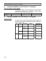
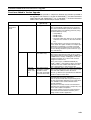
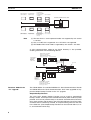
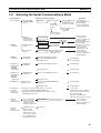
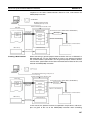
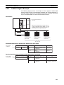
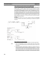
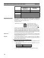
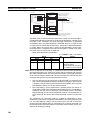
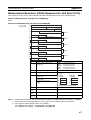
Section 1-4
Features
Bridge
Host Link
Ethernet Network
SEND(090),
RECV(098),
CMND(490)
Controller Link Network
Controller Link Network
Gateway
Protocol Macros
The main features of the protocol macro functions are described below. For
details, refer to the CX-Protocol Operation Manual (W344).
Wide Range of
Communications
Protocols
Communications are possible with virtually any general-purpose external
device, provided it has an RS-232C or RS-422A/485 port, supports halfduplex or full-duplex communications, and supports start-stop synchronization.
Send Frames and Receive
Frames Matching
Specifications
Send frames (command + data and other send frames) and receive frames
(response and other frames) can be created and registered according to the
communications frame specifications of the external device.
Communications-related
Functions
Error check code calculations, frame length calculations during sending, and
ASCII⇔Hexadecimal conversion of numeric data are supported.
Send/Receive Monitoring
Receive wait monitoring, receive completion monitoring, and send completion
monitoring are supported. If monitoring times are exceeded, send/receive can
either be terminated, or retry processing can be performed.
Retry Processing
Send/receive retry processing can be automatically executed when an error
occurs, simply by setting the number of retries.
PLC Read/Write Variables
in Send Frames and
Receive Frames
Variables for reading PLC memory can be included in the actual send frames.
These can be used as destination addresses or data when reading PLC data
while sending. Variables for writing to PLC memory can be also included in
the actual receive frames. These can be used to write the contents of destination addresses or data to the PLC during reception.
Switch 1:N
Communications or the
Data Write Destinations
Using Repeat Processing
Repeat processing (repeat counters) for send/receive processing can be
specified in communications sequences. This enables the same data to be
sent by switching destination addresses during communications 1:N (N = 32
max. due to restrictions in the physical layer) or by switching the PLC memory
write destination addresses during data reception.
PLC Interrupts During
Data Reception
An interrupt can be created in the PLC’s CPU Unit during data reception, and
an interrupt program can be executed in the CPU Unit. (The PLC interrupt
function is supported only for the Serial Communications Boards. This function cannot be used with Serial Communications Units.)
Next Process Switching
According to Receive Data
The contents of up to 15 set of expected receive data can be compared with
the receive data to determine the next process.
New Error Check Codes
LRC2 (two’s complement of LRC), and SUM1 (one’s complement of SUM)
have been added to the error check codes.
Step Queuing for Sync
Signal from the PLC
At any step of the communications sequence, the next process can be made
to wait until a sync signal from the PLC’s CPU Unit has been input. This
enables processing, such as data manipulations, to be performed in the CPU
Unit during the communications sequence.
Half-duplex or Full-duplex
Transmissions
With the conventional protocol macro functions, only half-duplex transmissions were possible. With half-duplex mode, the reception buffer is cleared
14