1
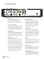
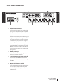
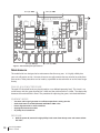
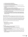
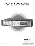
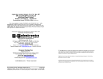
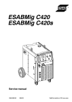
m201
Microphone Preamplifier / ADC
Owner’s Manual Rev G
All contents ©2012 Grace Design
4689 Ute Highway, Lyons, CO 80540 USA
tel 1.303.823.8100 fax 1.303.823.8101
[email protected] / www.gracedesign.com
Welcome
Thank you for purchasing the Grace Design m201 microphone preamplifier. With the combination of
unmatched sonic performance, useful features, and solid reliability, the m201 is a powerful recording
tool designed to help you make the best recordings of your career.
We have designed the m201 to be as easy and intuitive to use as possible. However, we strongly
recommend that you read this product manual thoroughly to familiarize yourself with the unique
features and capabilities of the m201.
Also, please do not hesitate to contact us directly if you have any questions, comments, or concerns
with your new m201 microphone preamplifier. Thanks for reading and happy recording!!
-The Grace Design Team
Contents
Welcome2
Important Safety Information
3
Front Panel Controls
4
Rear Panel Connections
5
Audio Connections
6
Power Connections
6
Preamplifier Operation
7
The Optional A/D Converter Features
9
Operating The A/D Converter Module
9
Adjusting A/D Converter Sensitivity
10
Maintenance11
Specifications16
2
Signal Flow Diagram
18
Warranty Information
19
Manual Revisions
20
grace design m201
owner’s manual
Important Safety Information
GENERAL
•
•
•
•
•
•
•
•
•
•
•
•
•
•
Indoor use only
Ordinary Protection: This equipment should not be exposed to dripping or splasing.
Avoid placing objects filled with liquids, such as vases or glasses, on this equipment.
Class I Equipment (grounded type)
Electrical rating: 100-120/220/230-240V~ 50-60Hz 30W
Mains supply voltage fluctuations are not to exceed ±10% of the nominal supply voltage.
Pollution Degree 2
Installation (Overvoltage) Category II for transient overvoltages.
Maximum Relative Humidity: <80%
Operation temperature range: 10 °C to 40 °C
Storage and transportation temperature range –40 °C to 70 °C
Maximum altitude: 3000m (9843 ft)
Equipment suitable for continuous operation
Weight: preamplifier - 7.5kg (16.5lbs)
SAFETY MARKING SYMBOLS
CAUTION: READ ACCOMPANYING DOCUMENTS
This symbol, located on the equipment and in this manual, refers to important
instructions. Read this manual thoroughly before operating this equipment.
WARNING: ELECTRICAL SHOCK HAZARD
This symbol, located on the equipment and in this manual, indicates the potential for electrical shock hazard.
SERVICE INFORMATION
The Grace Design m201 contains no user serviceable components. Contact Grace Design for repair and upgrade information. In the event that your Grace Design m201 needs to be returned to
the factory, contact us for a return authorization number.
grace design m201
owner’s manual
3
Front Panel Controls
1
2
3
1
40
2
40
30
48V
ribbon
50
30
(+10dB )
ribbon
50
(+10dB )
HI-Z
HI-Z
130V
20
60
m201microphone preamplifier
50m
50s
48V
130V
20
INPUT MODE
60
INPUT MODE
70m
30s
30m
70s
100m
M+S WIDTH
- 20dB
+48V
HI-Z
+48V
- 20dB
HI-Z
GRACE DESIGN USA
4
5
6
7
1. 24 position gold contact gain switch
Each gain control has 24 positions and adjusts the
voltage gain from 18dB to 64dB in 2dB steps. In
ribbon mode the gain range is 28dB to 74dB in 2dB
steps.
2. bi-color LED peak indicator
The LED peak indicator, which monitors the output
signal level, turns green at -14dB and switches to
red at +16dB (12dB before clipping). The threshold
level for peak indication is adjustable on each channel (see the calibration section of this manual).
3. input mode switch
The input mode switch is used to select between
the various types of inputs available with the m201,
including standard 48V, ribbon mic mode, HI-Z, or
the optional 130V DPA™ inputs. Refer to the m201
block diagram at the end of this manual for signal
routing details.
4. 48V phantom power switch
The phantom power switch (labeled +48V) connects
the +48V power supply to pins 2 and 3 on the XLR
input connector. This switch illuminates red. It
should be noted that the LED in this switch actually
monitors the phantom power voltage at the input.
With no microphone connected, the LED will continue to illuminate for approximately 10 seconds after
the phantom power is turned off as the filter capacitors discharge. As well, even if the phantom power
is switched off, the LED will illuminate if voltage is
being fed from an external source. (i.e. when using a direct split in a remote recording application.)
Also, the +48V switch is used to activate the +130V
DPA™ mic power if this option is installed.
9
8
5. polarity reversal switch
The polarity reverse switch reverses the absolute
phase of the music signal at the input of the preamplifier. The switch illuminates green and provides
power for a sealed gold contact relay located on
the preamplifier circuit board. This eliminates signal
wiring to the front panel and switch contact performance problems. The polarity reverse function is
active for all input connectors.
6. -20dB pad switch
The 20dB attenuator switch attenuates the input
signal 20dB. The switch illuminates amber when
engaged. Like the phase reverse switch, this switch
controls a sealed gold contact relay on the preamplifier circuit board. With the -20 switch engaged,
the effective gain range becomes -2dB to 44dB. The
20dB attenuator is active for 48V Phantom, ribbon
and (optional) DPA inputs. It does not affect the
HI-Z inputs.
7. HI-Z input
This 1/4 inch TRS input is active when the input
mode switch is in the HI-Z position. Suitable for any
high impedance source such as: bass guitar, acoustic
guitar, electric guitar, keyboards, etc... This input is
can be used balanced with a TRS connector or unbalanced with a TS connector.
8. M-S width control
This knob controls the ratio between the Mid and
Side signals in an M-S recording setup. Please see
the ‘preamplifier operation’ section of this manual
for complete information regarding this feature.
9. standby / power switch
Connects the mains voltage and turns on the
m201When depressed the pushbutton will illuminate green and the preamplifier will be on. When
released the preamplifier will be in standby mode.
4
grace design m201
owner’s manual
Rear Panel Connections
6
OUT
S/PDIF
PUSH
PUSH
PUSH
WC
m201microphone preamplifier
5
IN
4
1
3
TOSLINK
LEAD FREE
120Vac
Pb
AES 2
AES 1
PUSH
2
4
2
1
MIC IN
130 V
1
3
2
LINE IN
M+S OUT
PUSH
2
PUSH
1
RoHS
COMPLIENT
GRACE DESIGN USA
4
LEFT
RIGHT
3
OUT
OUT
MIC IN
OUT
OUT
2
MIC IN
1
1. XLR mic input connectors
Input connections are made via female XLR connectors with pin 2 positive, pin 3 negative and
pin 1 ground. 48V phantom power is supplied
on pins 2 and 3.
2. XLR output connectors
Parallel XLR outputs are provided for sending line
signals to two seperate recording devices or mixers. Output connections are made via male XLR
connectors with pin 2 positive, pin 3 negative
and pin 1 ground.
3. XLR outputs are provided for sending M-S signals independently of the standard line outputs.
Output connections are made via male XLR connectors with pin 2 positive, pin 3 negative and
pin 1 ground.
4. IEC AC power input
Accomodates the included 3 prong AC cable.
Connect to grounded outlet only.
5. 130V DPA microphone inputs (optional)
Accomodates 130V DPA© microphones via 4
pin XLR connectors. Note: this option is no longer
available.
6. Optional A/D Converter module
Optional A/D converter module for the m201 includes seperate balanced analog A/D line inputs,
2x AES3 outputs (single and dual wire), word
clock/ loop sync in and out, S/PDIF out and TOSLINK optical out.
grace design m201
owner’s manual
5
Audio Connections
Microphone input connections are made via female XLR connectors with pin 2 positive, pin 3 negative and pin 1 ground. 48V phantom power is supplied on pins 2 and 3. Output connections are
made via male XLR connectors with pin 2 positive, pin 3 negative and pin 1 ground. If the output is
to be used unbalanced, pin 1 should be connected to signal ground and pin 2 to signal hot. Due to
the nature of the balanced output stage, pin 3 should be left open for unbalanced operation. See
<figure 1> below. Note: This will provide a signal of positive absolute polarity when the preamplifier is being used with a microphone which produces a positive voltage on pin 2 with positive air pressure on the front of the diaphragm. While a vast majority of microphones conform to this standard a
few do not. Use the phase reverse switch to compensate if necessary.
HOT
2
GND
1
SHIELD
3 (open)
<figure 1> - Unbalanced output cable termination
To connect to the front panel HI-Z input, the input mode selector switch must be positioned in the
“HI-Z” location, which changes the preamplifier input source from the mic input connector to the
front panel TRS jack. The input impedance of the instrument input is 2M Ohm (balanced) and 1M
Ohm (unbalanced), which is ideal for inserting high impedance sources such as guitars with passive
pickups as well as any instrument with a high level output. Wiring of the HI-Z jack is Tip positive,
Ring negative, and Sleeve ground. Please note that the gain range of the preamplifier when using
the instrument input is –2dB to +48dB in 2dB steps.
Power Connections
A standard three prong AC power cable is included with the m201. For safety,
the power supply cord must be connected to a grounded outlet.
The Disconnect Device for the m201 is the Mains plug or the Appliance Coupler on the power supply cord. The Disconnect Device must remain accessible and operable
CHECK LINE VOLTAGE SETTINGS
Your m201 has been set from the factory to operate at the voltage required for your part of the
world. However, it’s important to double-check this in order to ensure no damage will come to the
unit if power is applied while the setting is incorrect.
AC input voltage settings can be adjusted for 100V, 120V, 220V, 230V and 240V operation at 50-
6
grace design m201
owner’s manual
60Hz. From the rear of the m201, open the trap door next to the IEC power inlet with a small screwdriver. Carefully pull the voltage select cam straight out and then insert with the desired voltage
showing. Do not try to rotate the cam while it is in the power input module. Replace the fuses
with the proper value selected from <figure 2> below. Be sure to use a time delay fuse with a 250V
rating.
CAM SETTING
100V~
120V~
230V~
230V~
240V~
<figure 2 - fuse value table>
LINE VOLTAGE
100V~
120V~
220V~
230V~
240V~
FUSE VALUE
250V~ T 500mA L
250V~ T 500mA L
250V~ T 315mA L
250V~ T 315mA L
250V~T 315mA L
Preamplifier Operation
TURNING THE POWER ON
The power switch is located on the m201 front panel. Pushing the power switch in turns the mains
power on (switch illuminates green). Pushing the power switch again turns the mains power off.
USING THE INPUT MODE SELECTOR SWITCH
The input mode switch to the right of the gain control provides a convenient way for the user to select between the various types of inputs the m201 can accommodate. The following is an overview
of the four settings:
48V This setting should be selected for all general recording applications with most microphone
types. In this position, the main XLR mic inputs are feeding the preamplifier and the dual XLR outputs are active. Proceed with the ‘setting the gain’ discussion below.
HI-Z This setting is used to select the front panel mounted 1/4” instrument DI inputs. These inputs
can accommodate a wide variety of high impedance input sources, including bass guitar, keyboards,
electric guitars etc... In this mode, the rear panel XLR inputs are not active, while the dual balanced
XLR outputs carry the amplified signal from the DI inputs. There is no 48V phantom available on this
input. The phase reverse switch is active, and the gain range of this input is -2dB to +44dB (20dB less
than the 48V input), so therefor the -20dB pad is not available. This connector is balanced with the
Tip positive, Ring negative and Sleeve ground.
ribbon This setting puts the m201 into ‘ribbon mic mode’, which is described in detail below. Use
this input for ribbon microphones or any application where an additional 10dB of gain may be required. In this position, the main XLR mic inputs are feeding the preamplifier and the dual XLR outputs are active.
130V This setting activates the optional 130V input module for DPA microphones. If the 130V input
grace design m201
owner’s manual
7
option is present, this selection will deactivate the standard XLR inputs and enable the dedicated 4
pin 130V XLR inputs. In this mode, the 48V pushbutton switch will turn on the 130V power supply.
Phase reverse and -20dB pad are available in this mode. The dual balanced XLR outputs carry the
output signal. Note: this option is no longer available.
SETTING THE GAIN
First, turn the gain control fully counter-clockwise and check that the 48V phantom power is off.
Connect a microphone and then turn on the phantom power if required. When sending a signal to
a recorder, converter or interface that has fixed input levels, simply increase the gain until the optimum recording level is reached. If the peak indicator flashes red excessively with the gain control in
the fully counterclockwise position, engage the -20dB attenuator.
When sending a signal to a recorder with an input attenuator (i.e. the record level control on a DAT
or CDR recorder) use the following procedure: With the sound source present, turn the gain control
clockwise until the peak LED begins flashing red, then reduce the gain until the red stops flashing. Since red indicates a peak level which is 12dB before preamplifier clipping (6dB in unbalanced
mode), it is OK for it to come on periodically during recording. If peak indicator flashes red excessively with the gain control in the fully counterclockwise position, engage the -20dB attenuator. Now
adjust the recorder input control for the optimum recording level.
Ribbon Mic Mode
Selecting the ribbon mic position on the input mode switch optimizes the channel for ribbon microphones by boosting the gain by 10dB while disabling 48V phantom power and optimizing the mic
input impedance. Before activating ribbon mic mode, make sure the channel’s gain is fully down
(counter-clockwise) and 48V phantom power is off. Now simply select ‘ribbon’ input mode and turn
the gain control upwards until the proper recording level is achieved.
If you press the 48V phantom switch while the ribbon switch is engaged, the mic power will not turn
on. However, if the 48V phamtom switch remains depressed and the input mode switch becomes
inadvertently changed to ‘48V’, 48V phantom will consequently be activated, which can potentially
harm a ribbon your microphone if it is still connected to the input. If the 48V phantom power switch
is turned of and then the ribbon mode is selected, the preamplifier will wait until the phantom power voltage has completely discharged and then the ribbon mode will activate automatically.
An additional benefit of the ribbon mic mode is that the input DC blocking capacitors are relay bypassed to further simplify the m201’s signal path. Incidentally, the ribbon mode works very well with
many lower output dynamic microphones as well as ribbon types.
M-S recording
In M-S mode the m201 accepts the Mid signal in channel 1 and the Side signal in channel 2. The LEFT
channel output connector provides the “sum” of the inputs and the RIGHT channel output connector
provides the “difference” of the inputs. In M-S mode, the M-S width control adjust the ratio of Mid
signal to Side signal in the dedicated M-S outputs. The LEFT and RIGHT M-S outputs are always active which allows the user to record the discreet Mid and Side signals from the preamplifier Channel
8
grace design m201
owner’s manual
1 and 2 outputs while also recording (or monitoring) the stereo composite from the M-S LEFT and
RIGHT outputs. Note: For more information on M-S recording we would highly recommend the AES paper written by Wes Dooley and Don Streicher called “M-S Stereo: A Powerful Technique for Working in Stereo”. This paper (No. 1792) is available from the Audio Engineering Society web page (www.aes.org).
The Optional A/D Converter Features
1
FS SELECT
CLOCK SOURCE
44 48
INT WORD LOOP
88
96 176 192
1
2
14 16 18 20
CH1-2 MS
< -0.4 -0.3 -0.2 -0.1
CAL
0
-6
-5
-4
0.1 0.2 0.3 0.4 >
LEVEL
LINE
A
7
-3
-2
-1
4
0
OVER
B
INPUT SENS
ADC SOURCE
8
PRO 2WIRE CONS
OVER
-60 -50 -40 -32 -28 -24 -20 -18 -16 -14 -12 -10 -8
HEADROOM (dB)
9
ADC MODE
sLOCK
OFF
10
3
2
6
PEAK RESET / MODE
(hold)
5
1. FS SELECT this switch is used to toggle through the available ADC sampling rates
2. CLOCK SOURCE this switch is used to select the ADC clock source
3. ADC MODE this switch is used to select single or dual wire AES, and switch between either professional
or consumer fomat
4. OVER lights illuminate when the ADC has been overloaded, and remain lit until the PEAK RESET swich is
pushed
5. PEAK RESET / MODE This switch is used to clear peaks on the 20 segment led meter and to select how
the meters display peak information.
6. INPUT SENSITIVITY CALIBRATION SCALE
7. INPUT SENS selects between the two programmable ADC input sensitivity settings.
8. ADC SOURCE selects the input source which feeds the ADC module
9. ADC headroom indicator
10. 20 segment LED level meter
Operating The A/D Converter Module
If you have purchased the optional A/D converter module for your m201, the following section will
help you become familiar with its features and its operation. The m201 A/D card is available installed
on new m201’s from the factory, or as an upgrade to your existing m201. If you need more information about upgrading your m201 with the A/D module, please feel free to call us at 303.443.7454.
INPUT SOURCE SELECT The m201 A/D can receive signals from 3 different inputs: channels 1&2
from the mic preamplifier section, the M-S matrix outputs, or the external balanced line inputs (located on the back panel of the A/D module). The A/D source select switch (lower left) is used to toggle
between the three input source options, which are illuminated green directly above in the bezel.
grace design m201
owner’s manual
9
Simply push the button to select the input source you require.
FS SELECT The m201 A/D converter can operate at sampling rates of 44.1, 48,88.2, 96, 176.4, and
192kHz. Whether operating on the internal crystal or an external clock source, you must select the
appropriate sampling rate at which you wish to record. The top left switch above the A/D bezel labeled FS SELECT is used to toggle between all the available sampling rates. Simply push the button
to select the sampling rate you require. The selected rate will be illuminated green below. Selecting
“OFF” puts the A/D converter circuitry in low power standby mode with all oscillators off.
CLOCK SOURCE The m201 A/D can be run from the internal crystal, an external word clock source,
or from Avid™ loopsync. The top middle switch, labeled CLOCK SOURCE, is used to select between
these options. The selected clock source will be illuminated green below the switch.
A/D MODE The m201 A/D is capable of transmitting AES/EBU digital audio in single or dual wire
modes, and in either professional or consumer format. The upper left switch selects between these
various formats. The selected format will be illuminated green below the switch.
PEAK RESET / MODE High resolution 20 segment metering is included with the m201 A/D option.
When A/D input signals hit or exceed absolute zero (0dBfs), the over indicator lights (‘over’ placed
above and below ‘0’ on the meter) will illuminate red and remain lit until the peak reset switch is
pushed.
Peak signal levels are indicated by the highest level LED remaining lit. The peak indicators can programmed to remain lit indefinitely until the reset switch is pressed (infinite); stay lit for 4 seconds
(delay); or not stay lit at all (off ). These three modes are selected by simply pressing and holding the
PEAK RESET / MODE switch for approximately 3 seconds, which toggles through the three available
modes.
Adjusting A/D Converter Sensitivity
The m201 A/D converter features two independent A/D sensitivity configurations. The front panel interface allows the user to easily switch between these two calibrated settings. Each of the two input
sensitivity ranges (A) and (B) can be configured for one of four standard A/D sensitivities. The following sections detail the operation and calibration of this feature.
SELECTING THE A/D SENSITIVITY From the m201 front panel interface, pressing and releasing the
INPUT SENS push button toggles the selected A/D input sensitivity. The currently selected range (A)
or (B) is illuminated.
CALIBRATING THE A/D SENSITIVITY The m201 ships with the following two default sensitivity calibrations: (A)+22dBu = 0dBFS (18dB Headroom) (B)+18dBu = 0dBFS (14dB Headroom).
Internal trim controls allow you to reconfigure either (or both) of the sensitivity levels.
10
grace design m201
owner’s manual
Four standard sensitivities are supported in the m201 A/D converter: +18dBu = 0dBFS (14dB Headroom) +20dBu = 0dBFS (16dB Headroom) +22dBu = 0dBFS (18dB Headroom) +24dBu = 0dBFS
(20dB Headroom).
The front panel interface features a calibration mode that allows precise adjustment of the A/D sensitivity. To recalibrate one or both of the input sensitivity configurations, simply do the following:
1. Disconnect AC power from the m201.
2. Remove the 8 top cover screws using a #2 Phillips screwdriver. Lift the top cover off the unit and
set it aside.
3. Reconnect AC power to the m201 and turn it on.
4. Connect a signal generator to the A/D LINE inputs. Set the signal generator output to +4dBu @
1kHz (1.29V rms).
5. Turn on the m201 A/D converter and select LINE as the A/D input source.
6. To enter CAL mode, press and hold the INPUT SENS button for approximately 3 seconds. The normal operation displays will extinguish and the CAL indicator will begin flashing indicating CAL
mode is active. The current input sensitivity range (A) or (B) will be illuminated along with that
range’s current sensitivity calibration (shown as “dB Headroom” in the bottom left of the meter
display).
7. Press and release the INPUT SENS button to select the range (A) or (B) that you wish to calibrate.
8. Press and release the A/D SOURCE button to scroll through the 4 available sensitivities until the
desired setting is illuminated.
In calibration mode, the digital audio meter is configured such that the “0” position is the target
sensitivity level. The meter then indicates the current signal level versus this target sensitivity. The
meter will display a window centered around the target sensitivity with a +/- 0.4dB width (in 0.1dB
increments). When the sensitivity adjustment on the A/D converter is calibrated for the selected setting, only the “0” LED will be illuminated. If the signal level is high, the 0 indicator will be illuminated
along with the error (in 0.1dB increments) to the right of 0. If the signal level is low, the 0 indicator
will be illuminated along with the error (in -0.1dB increments) to the left of 0.
On the m201 A/D module, trim pots are used to adjust the (A) and (B) ranges for each channel. Each
of these are labeled on the A/D module circuit board <figure 3>.
1. Locate the appropriate trimmer for the channel you wish to adjust. If the current signal level is
high, you need to decrease the A/D sensitivity. Using a non conductive tool, turn the appropriate
trim pot counter-clockwise to reduce the level until only the “0” is illuminated on the m201 meter.
If the current signal level is low, you need to increase the A/D sensitivity by turning the appropriate trim pot clockwise to increase the level until only the “0” is illuminated on the LED level meter.
2. Once all desired calibration adjustments have been made, press and hold the INPUT SENS button
for approximately 3 seconds. This will exit CAL mode and return the A/D to normal operation. The
new settings are now stored until future changes are made.
3. Power down the unit, disconnect the AC power and reinstall the top cover.
grace design m201
owner’s manual
11
CH2 (A): VR3
P5
P6
CH2 (B): VR4
J5
FRONT PANEL
C42
P3
U11
C29
C20
U4
J4
-18V
J2
C13
+15VA
R9
C31
C21
R16
D1
K1
Q1 C10
U5
D2
R10
-15VA +6.5V +3.3V
C46
P4
TP6
C40
U9
R29
K7
R19
Q2 R13
K2
K3
D3
VR2 A
1
VR1 B
1
1
3362
3362
3
3
C15D7
C11
K4
D4
D5
D6
C30
C12
CH1 (B): VR1
FD1
P1
P2
K5
R31
2
3
3362
1
B VR4
A VR3
3
3362
R22 C25
1
C41
R32
C36
R23 R26
C17 C32
C14
Q3
R15
R12
R14
K6
TP4 TP5
R38
R39
Q4
C43 U10
C50
C27
R35
U3
R34
C6
R11
TP3
C51
U16
U15
C4
D8
TP1 TP2
+18V
C48
C24 C26
R28
C45
C47
P in 1
AT136 REV
R44
R43
R42
R37
R41
C54
G R A C E D E S IG N
CH1 (A): VR2
<figure 3 - A/D sensitivity trim pot locations>
Maintenance
The model m201 was designed to be maintenance free for many years. It is highly unlikely that
your unit will require service. However, there are two adjustments that may need to be made from
time to time. These procedures can be made by a qualified service technician or at the Grace Design
factory.
PEAK LED ADJUSTMENT PROCEDURE
The peak LED threshold levels may be adjusted to a user defined operating level. This circuit is set
at the factory with the green threshold at -14dBu and the red threshold at +16dBu. The relationship
between the two thresholds is fixed. The procedure for adjusting the green / red threshold follows:
EQUIPMENT NEEDED
•
•
•
•
•
Sine wave audio signal generator or oscillator output from a mixing console.
Audio level meter or an RMS Volt meter with dBu or dBm scales
Plastic alignment tool or small screwdriver
Appropriate interconnect cables
#2 phillips head screwdriver
PROCEDURE
1. With the power off, remove the eight phillips head screws from the top cover and remove it from
the m201.
12
grace design m201
owner’s manual
2.
3.
4.
5.
6.
7.
Set all of the gain controls to the 30dB position.
Connect the audio generator to the input of channel 1.
Set the generator output level to approximately -20dBu @1KHz.
If the generator has an unbalanced output, refer to figure 2 below for termination information
Connect the level meter to the output of channel 1.
If the level meter has an unbalanced input, refer to <figure 1> for unbalanced output termination
information.
8. Apply power to the generator, preamplifier, then the level meter.
9. Adjust the generator output level so that the preamplifier output level is at the desired red threshold. If the proper level can’t be reached, adjust the preamplifier gain control.
10. Locate VR2A (VR2B for channel 2) (see <figure 3>) on the channel 1 audio circuit board and adjust
until the peak LED is between green and red. The color should appear amber when the setting is
correct. Repeat this procedure for channel 2.
11. If it is desired to calibrate the peak indicator to a specific converter/recorder input level, simply
connect the output of the preamplifer to the converter/recorder. Adjust the signal generator so
that the desired peak level is indicated on the recorder and then adjust VR1 until the peak LED is
between green and red.
INPUT OFFSET ADJUSTMENT
The input amplifiers in the m201 are ultra-precision laser trimmed devices which have a very low
input offset. However, even the smallest differential offset at the input can result in an audible “click”
when the gain control is turned. It should be noted that this type of click will be audible when no
signal is present. With no signal present there is no signal amplitude to be changed unless input offset is present. This procedure nulls the input offset and minimizes the clicking sound with no signal
present. In contrast, there will almost always be an audible click if turning the gain control while a
signal is present. This is because the gain control, being a stepped control, will make an instantaneous change in amplitude when turned, which creates a transient signal.
EQUIPMENT NEEDED
•
•
•
DC Volt meter with at least 1mV sensitivity
Plastic alignment tool or a small screwdriver
#2 phillips head screwdriver
PROCEDURE
1.
2.
3.
4.
Remove the 8 phillips head screws from the top lid but leave the lid in place.
Set all of the preamplifier gain controls to maximum.
Turn on the m201 preamplifier and allow to warm up for at least 45 minutes.
Remove the top lid and locate the DC offset test points TP1A and TP2A (see figure 4 below). Place
the Volt meter probes into these holes.
5. Locate DC offset potentiometer VR1A (VR1B for channel 2) and rotate it for a reading of 0.000VDC
+/- 0.003V.
6. The input offset does drift with temperature and having the lid off will allow the circuitry to cool. It
is advisable to replace the lid and let the preamplifier warm up again (about 20 minutes) and then
re-check your adjustments.
grace design m201
owner’s manual
13
D1B
D4B
Q1B
Q1A
C38B C37B
D4A
C30B C29B
C38A C37A
C30A C29A
D1A
R5A
K1A
R5B
K5A
K3A
D3A
P2
U10B
U6B
U5B
R38B
R37B
D10B
C45B
R63B
C44B
R62B
D17B
D16B
R53B
C35B
D13B
C43B
C42B
R61B
R60B
R52B
R51B
D14B
J4B
J3B
CHANNEL 1 CHANNEL 2
VR2B
U7B
R26B
R25B
C23B
C22B
R69B
R34B
R33B
D9B
R30B
R31B
C25B
C24B
D7B
D8B
R29B
R28B
C27B
R27B
C13B
C36B
R59B
R54B
C39B
R67B
R16B
R15B
R18B R17B R14B
C4B
C46B
R64B R55B
R56B R50B
C52
D15B
J7B
R45B
R46B
R39B
R32B
U1B
U8B
R40B
Q3B Q2B
R71
R48B R47B
R41B
D2B
R70
C1B
J4A
<figure 4 - offset test point and peak LED adjust trim pots>
grace design m201
owner’s manual
R20B
C10B
R60A
R52A
R51A
D14A
D12B
C15B
U5A
R21B
R3B
C50
FRONT PANEL
14
TP2B TP1B
J3A
P1
R38A
R37A
D10A
C13A
RED WIRE
C27A
R27A
R26A
R25A
C23A
C22A
R4B
R6B
R2B
R1B
C4A
U6A
C45A
R63A
C44A
R62A
D17A
D16A
R53A
C35A
D13A
C43A
C42A
R61A
C20B
C19B
U13
R8B R7B
R16A
R15A
R18A R17A R14A
R8A R7A R6A
R2A
R1A
C1A
U7A
VR2A
U1A
C10A
C25A
C24A
D7A
D8A
C14 R29A
R28A
C51 TP6 C53
+15
U12
J1B
R69A
C8
R45A
R46A
R39A
R32A
R19
R9
Q4B
U3B
TP5
-15
U10A
R20A
R3A
PEAK LED CAL POTS:
CH1> VR2A
CH2> VR2B
R67A
U4
C5B
C36A
R59A
R54A
C39A
R34A
R33A
D9A
R30A
R31A
R21A
R4A
OFFSET
J7A
J1A
U2
R40A
Q3A Q2A
OFFSET TEST POINTS:
CH1> TP1A-TP2A
CH2> TP1B-TP2B
C6B
U8A
C19A
TP3 C12 TP4 C17
-15
+15
C46A
R64A R55A
R56A R50A
C5A
R48A R47A
R41A
D2A
C20A
P8
R49B
VR1B
D15A
D12A
C15A
TP2A TP1A
OFFSET
U3A
C6A
D3B
R22B
R22A
R11A
Q4A
VR1A
K3B
P5
P4
R49A
K5B
K1B
R11B
OFFSET TRIM POTS:
CH1> VR1A
CH2> VR1B
P7
RED WIRE
Cleaning
Your m201 preamplifier chassis is constructed out of high quality stainless steel. Under normal circumstances, virtually no maintenance is required to keep the unit looking shiny and new. However,
if your unit becomes smudged or dirty, here are some cleaning tips: We recommend using either
Pledge furniture polish or Zep brand stainless steel cleaner (available at the hardware store). Apply
cleaner to a clean, dry, lint free cloth and gently wipe all stainless surfaces, taking care not to allow
the cleaning product to build up around the panel switches or knobs.
grace design m201
owner’s manual
15
Specifications
preamplifier specifications (without A/D converter)
Frequency Response
@ 40dB gain ± 0.2dB (50Ω source)
@ 40dB gain ± 3dB (50Ω source)
18Hz-65kHz
4.5Hz-350kHz
THD+N
@ 20dB gain +25dBu out, 1kHz
<.0008%
@ 40dB gain +25dBu out, 1kHz
<.0009%
@ 60dB gain +25dBu out, 1kHz
<.0070%
Intermodulation Distortion
@ 40dB gain +25dBu out
SMPTE/DIN 1:1 (50Hz, 7kHz)
<.0020%
SMPTE/DIN 4:1 (50Hz, 7kHz)
<.0030%
Noise - Referred to Input
@ 60dB gain 50Ω source
-130dB
@ 60dB gain 150Ω source
-127dB
@ 60dB gain 600Ω source
-123dB
Phase Deviation
100Hz-20kHz @40dB gain
<3°
Crosstalk
Any Channel @ 40dB gain 1kHz
-125dB
Any Channel @ 40dB gain 10kHz
-115dB
CMRR
@ 60dB gain, 3.5Vcm, 1kHz
>70dB
@ 60dB gain, 3.5Vcm, 10kHz
>70dB
Maximum Output Level
1kHz, 100KΩ load
+28dBu
Impedance
Input
8100Ω
Input, ribbon mode
20kΩ
Output
190Ω
Peak Led Meter
Green threshold
-14dBu
Red threshold
+16dBu
Weight and Dimensions
dimensions
weight
2U, 19” rack mount x 10” deep
16.5lbs (7.5kg)
Power Consumption
100/120/230/240V~ 50-60Hz
16
grace design m201
owner’s manual
20 Watts Max
A/D module specifications (line input)
Dynamic range
20Hz-20kHz
>115dB
“A” weighting
>117dB
THD+N
1kHz, -1dBFS, 20Hz-22kHz
Frequency response
< 0.00026% (-112dB)
+/-0.2dB
-3dB
44.1kHz Fs
5Hz-21kHz
22kHz
48kHz Fs
5Hz-23kHz
24kHz
88.2kHz Fs
5Hz-41kHz
44kHz
96kHz Fs
5Hz-45kHz
48kHz
176.4kHz Fs
5Hz-54kHz
72.5kHz
192kHz Fs
5Hz-59kHz
Full scale input level
79kHz
+16dB or +24dB (+/-2dB trim)
CMRR
60Hz
>65dB
1kHz
>80dB
10kHz
>60dB
IMD SMPTE 4:1 60Hz, 7kHz, -3dBFS
Interchannel crosstalk
<100dB (0.0008%)
<120dB
Group delay
44.1-48kHz
Sample rates, internal crystal (kHz)
13/Fs
44.1, 48, 88.2, 96, 176.4, 192
External Clock Lock Range
Wide lock mode
s-Lock™ mode
40.1kHz-207kHz (+/-8% at each sample rate)
+/-250ppm (+350, -400ppm typical)
Intrinsic Jitter, 200Hz-20kHz BW
Wide lock mode
< 60ps RMS
s-Lock™ mode
< 40ps RMS
Jitter Rejection Corner Frequency
Wide lock mode, -3dB, 12dB/octave
s-Lock™ mode, -3dB, 12dB/octave
800Hz
10Hz
A/D sensitivity
Range A
+22dBu = 0dBFS (18dB headroom*)
Range B
+18dBu = 0dBFS (14dB headroom*)
*can be calibrated for any setting between +18dBu = 0dBFS and +24dBu = 0dBFS
grace design m201
owner’s manual
17
Signal Flow Diagram
INPUTS
CH1 MIC
CH1 HI-Z
CH1 DPA
DPA INPUTS (OPTIONAL)
INPUTS
CH2 MIC
CH2 HI-Z
CH2 DPA
DPA INPUTS (OPTIONAL)
ADC INPUTS
FROM PREAMP CH 1-2
6-CHANNEL
FROM M-S OUTPUT
LINE IN LEFT
LINE IN RIGHT
WORD CLOCK
LOOP SYNC IN
+48V
-20dB
-20dB
-20dB
HI-Z INPUT AMP
+130V
+48V
-20dB
HI-Z INPUT AMP
+130V
RIBBON +10dB
+48 OFF
RIBBON +10dB
+48 OFF
GRACE DESIGN
SIDE
MID
m201 SIGNAL FLOW DIAGRAM
MICROPHONE AMPLIFIER
MICROPHONE AMPLIFIER
CLK SELECT
FS SELECT
ADC INPUT SELECTOR
CLOCK CONTROL
CLOCK OUT SELECT
ADC
M-S WIDTH
OPTIONAL ANALOG TO DIGITAL CONVERTER MODULE
WIDE RANGE PLL
s-Lock PLL
INTERNAL CLOCK
BALANCED
OUTPUT DRIVERS
6-CHANNEL
M-S SUMMING
AMPLIFIER
M-S DIFFERENCE
AMPLIFIER
BALANCED
OUTPUT DRIVERS
2-CHANNEL
AES3 TX
AES3 TX
ANALOG OUTPUTS
CH 1 OUT A
CH 1 OUT B
M-S OUTPUTS
LEFT OUT
RIGHT OUT
ANALOG OUTPUTS
CH 2 OUT B
CH 2 OUT A
DIGITAL OUTPUTS
AES3 1
AES3 2
TOSLINK
2-CH SPDIF
CLOCK OUT
grace design m201
owner’s manual
18
Warranty Information
Grace Design warrants all of our products to be free of defective parts and workmanship for a period
of five years.
This warranty period begins at the original date of purchase and is transferable to any person who
may subsequently purchase the product during this time.
This warranty excludes the following conditions: normal wear and tear, misuse, customer negligence,
accidental damage, unauthorized repair or modification, cosmetic damage and damage incurred during shipment.
During the time of this warranty, Grace Design will repair or replace, at its option, any defective parts
or repair defective workmanship without charge, provided the customer has appropriate proof of
purchase and that the product has its original factory serial number.
Customers within the US are responsible for all inbound freight charges to Grace Design's facility,
while Grace Design will pay for return freight charges via ground service. Customers outside the US
must contact their distributor for warranty / product return details.
In order for Grace Design to provide efficient and timely warranty service, it is important that you
mail the completed warranty registration card enclosed with all of our products within 10 days of the
original date of purchase. You may also register your product directly with Grace Design by telephone
(303-823-8100 Monday-Friday 9:00am to 5:00pm MST), or you can register your product online at
www.gracedesign.com.
This warranty is in lieu of all other warranties whether written, expressed, or implied, INCLUDING ANY
WARRANTIES OF MERCHANTABILITY OR FITNESS FOR A PARTICULAR PURPOSE. In no event will Grace
Design be liable for lost profits or any other incidental, consequential or Exemplary damages, even if
Grace Design is aware of the possibility of such damages.
In no event will Grace Design's liability exceed the purchase price of the product. This warranty gives
the customer specific legal rights. The customer may also have other rights, which vary from state to
state. Some states do not allow limitations on implied warranties or consequential damages, so some
of the limitations of the above may not apply to a particular customer.
grace design m201
owner’s manual
19
Manual Revisions
Revision
Page
A
B
20
3
Change
Date
Initials
Initial release
04/25/2007
mbg
Changed voltage range and power specifications
04/26/2007
mbg
B
4
Power switch description changed to standby switch.
04/26/2007
mbg
B
6
Added power mains disconnect information
04/26/2007
mbg
B
13
Added signal flow diagram
04/26/2007
edg
C
9-12
Added A/D module infirmation
11/08/07
edg
D
7
changed fuse values for 220V-250V from 250 to 315mA
4/24/08
edg
E
5
Fixed rearpanel A/D panel illustration
4/15/09
edg
F
7
Changes Fuse Table values, formatting
4/9/2012
edg
G
7
Noted that DPA option is no longer available
5/3/2013
edg
grace design m201
owner’s manual