1
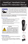
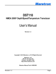
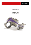
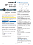
Model No. D10D
INSTALLATION AND OPERATION MANUAL
D10DX.06T – Digital Depth Sounder with Air & Water Temperature, Thru-Hull Transducer
To ensure safety and many years of trouble-free
operation of your product, please read this
manual carefully before using this product.
SAFETY INFORMATION:
•
•
•
•
•
Periodically wipe the face with a dry cloth. Do not use abrasives or solvents
on this device.
Only qualified personnel should perform repairs or servicing not covered in
this manual.
The LCD used in the product is made of glass. Therefore, it can break
when the product is dropped or impacted.
Keep this product away from heat sources such as radiators, heaters,
stoves and other heat generating sources. Do not store in extreme
temperatures above 150° F (65° C).
Shade the LCD during storage. Do not expose LCD to direct sunlight for
extended periods of time. Use the supplied cover at all times during
storage.
NOTES, NOTICES, AND CAUTIONS
WARNING: Indicates a potential for property damage, personal injury or
death.
IMPORTANT: Indicates potential damage to the device and tells you how to
avoid it.
NOTICE: Indicates important information that helps you make better use of
the device and tells you how to correct a performance problem.
INFORMATION: Indicates resources to obtain the proper information to help
you make the most of your device.
INFORMATION:
Read this manual completely before attempting to use or
install your device. Visit our Customer Service Center on our
website for advanced troubleshooting and technical support.
WARNING:
This depth sounder should not be used as a navigational aid
to prevent grounding, boat damage, or personal injury. Always
operate the boat at slow speeds in unfamiliar water, or if you
suspect shallow water or submerged objects.
w w w . h a w k e y e e l e c t r o n i c s . c o m
PARTS SUPPLIED IN PACKAGING
The following parts should be included with the display:
•
•
•
•
•
•
•
Digital Depth Sounder Display
White and Black Faces and Bezels (optional on some models, see package
for details)
Display Sun Cover (optional on some models, see package for details)
Thick Dash Extension Rod (optional on some models, see package for
details)
Flush Mount Bracket and Hardware
Display Power Harness and Waterproof Fuse Holder Attached to the Unit
Air Temperature Sensor and Harness Connected to the Display
The following parts should be included with the transducer:
•
•
•
•
Thru-Hull Transducer with Integrated Temperature Sensor, 30 ft Cable and
Connectors
Rubber Gasket
Plastic Nut
Integrated Temperature Sensor
If any items are missing or damaged, please contact our customer service
department.
SELECTING THE PROPER TRANSDUCER INSTALLATION
The D10DX is available with either a Transom Mount (D10DX.01T) or a Plastic
Thru Hull (D10DX.06T) Transducer. This package includes a plastic Thru-Hull
Transducer that can ONLY be Transom Mounted.
The Thru Hull Transducer (D10DX.06T) is suitable for the following vessels:
• Outboard, inboard/outboard, single or dual inboard, or jet-drive propulsion.
•
Hull dead rise angle below 20°.
•
Fiberglass or Metal Hull Material. CANNOT be constructed of wood.
• Hull thickness LESS than 1.25” (32 mm)
The Transom Mount transducer (D10DX.01T) is suitable for the following
vessels:
• Outboard, inboard/outboard, single inboard, or jet-drive propulsion.
• Hull dead rise angle below 30°.
• Transom angle from 3-20°.
If you think that the thru-hull transducer is not suitable for your installation, return
to the place of purchase and exchange for the transom mount (D10DX.01T).
You can also visit our Customer Service Center at www.hawkeyelectronics.com
to contact us or to complete a transducer exchange request to exchange the
w w w . h a w k e y e e l e c t r o n i c s . c o m
transducer for one that is specialized for your vessel. You may also call 888766-7276 to inquire about exchanging the transducer.
INSTALLING THE DISPLAY
Tools & Supplies Required for Installation
•
•
•
•
•
Electric Drill
2” Hole Saw
Wire Connectors Suitable for Connecting the Power Wire to Your Vessel
Wire Cutting/Crimping Tool
Marine Sealant/Caulk
STEP 1
Installing the Display
1. Find a location on the boat that will allow clear viewing of the display. Keep
in mind that the wires for the transducer and power must reach the mounting
location.
2. After finding the right location, mark a 2-inch hole. (If your boat has a pre-cut
hole in the dash panel, simply remove the hole plug and proceed to Step 5.)
IMPORTANT:
Check behind the desired cutting area for wires, switches, etc. that
may be damaged during cutting. If these obstructions are present,
use masking tape to hold them out of the way during cutting.
3. Cut out the 2-inch hole using the 2” hole
saw.
4. Seal any exposed wood with a marine
sealant.
5. Insert the display from the front of the panel,
feed the wires through the bracket and install
the bracket and locking nut from the rear of
the panel. Make sure that the face of the
display is rotated upright and aligned to your
satisfaction for easy viewing from the
vessel’s helm.
w w w . h a w k e y e e l e c t r o n i c s . c o m
NOTICE:
The display can also be surface mounted using
the Adjustable Surface Mount Bracket (1000-10).
Please visit our website or contact us by phone
for purchase information. You must attach the
extension rod to the mounting stud on the back of the display housing
before inserting the display into the Surface Mount Bracket.
STEP 2
Installing the Face and Bezel
1. Place the face (B) over the display making
sure to line up the cut outs on the face with
the notches on the display.
2. While holding the bezel (A), place it over
the display and turn clockwise until the
bezel locks into place.
NOTICE:
Gold and Chrome Alloy Bezels can be purchased on our
website to match your factory dash or give your Digital Depth
Sounder a custom appearance (P/N: 1000.20, 1000.22).
STEP 3
Installing the Air Temperature Sensor
The air temperature sensor is already installed on the back of the display housing
and includes a short harness.
• To install simply route the wire so that the end is located in the area where
you would like to take air temperature readings.
• Keep in mind that the sensor is located at the end of the harness and
should be kept away from direct sunlight, enclosed compartments, and
external heat sources.
NOTICE:
The water temperature sensor is located in the transducer. It
will be installed and connected during the transducer
installation process.
w w w . h a w k e y e e l e c t r o n i c s . c o m
STEP 3
Connecting of the Power Cable
The display has no ON/OFF switch. Therefore, you will
need to connect the power harness to a power source that
will turn the unit on as power is applied. The key switch or
an ON/OFF power switch will be suitable for powering the
unit.
1. Connect the BLACK wire in the harness to a negative (-)
terminal or suitable ground.
2. Connect the RED wire in the harness to a positive (+) 12
Volt switchable power source (key switch, on/off switch,
terminal block, etc).
NOTICE:
Never use “Twist-On” or “Automotive” type
connectors. These connectors form a solid electrical
connection and are less likely to corrode.
STEP 4
Testing the Display Installation
Before continuing with your installation, you
should test the unit to make sure the power wires
are properly attached.
1. Apply power to the unit by turning on the
power source that you’ve attached the red
and black wires to.
2. The buzzer should beep three times while the display
illuminates all the LCD graphics for 2 seconds. “---”
will then be shown on the LCD.
If the display operates as per #2 above, continue to the
“Basic Operation” section.
If the display does not turn ON:
1. Check the power source using a test light or DC volt
meter. Make sure there is 12 volt power where the
power harness connects to both the positive and
negative sources.
2. Check the fuse holder assembly with a test light or DC
volt meter. Connect the ground for the test meter or
light to the vessel’s negative power source.
w w w . h a w k e y e e l e c t r o n i c s . c o m
3. Remove the fuse and check for 12 volt power at the spring located inside the
fuse housing that is connected to the vessel’s power source. If 12 volt power
is present continue to the next step. If power is not present, return to Step 1.
4. Insert the fuse and check for 12 volt power at the end of the fuse. If 12 volt
power is present continue to Step C. If power is not present, replace the
fuse.
5. Reassemble the fuse housing. Strip back a quarter of an inch of wire cover
on the display side of the fuse housing and test for 12 volt power. If 12 volt
power is present continue to Step 2.D. If power is not present, replace the
fuse housing assembly.
6. Visit our Customer Service Center on our website or call 888-766-7276 for
advanced technical support.
NOTICE:
The fuse used in the In Dash Depth Sounder is a .25A, 250V
fuse. Do not rely on a visual inspection of the fuse to determine
if it is functioning. If your depth sounder will not turn on,
ALWAYS test the fuse with a test light or voltage meter.
GETTING TO KNOW YOUR DIGITAL DEPTH SOUNDER DEPTH
The unit’s auto-ranging, auto-sensitivity features means
that you never have to worry about adjustments. Simply
turn the power on, and you’re ready to go. The Depth
Sounder emits sound signals that travel through water, and
then calculates the amount of time that elapsed while the
signal traveled down to the bottom and returned back to
the transducer. This time is calculated by the microprocessor and displayed as a
depth reading. Extremely dirty water, very soft bottom, high speeds, deep water,
or a combination of the above will result in incomplete or inaccurate readings.
Under these conditions variable readings or “- - -” will be displayed.
NOTICE:
This depth sounder has a non-volatile memory. ALL
settings will be stored when the power is turned OFF.
DISPLAY MODE SELECTION
The unit has 3 user selectable modes:
• Depth Sounder
• Water Temperature
• Air Temperature
w w w . h a w k e y e e l e c t r o n i c s . c o m
To Change the Mode:
1. Press the “UP” Button to change the mode to the Right (The display will
change modes from Depth to Water Temperature to Air Temperature)
2. Press the “DOWN” Button to change the mode to the Left (The display will
change modes from Depth to Air Temperature to Water Temperature)
NOTICE:
When a Temperature Mode is selected the Water or
Air indicator will flash on the LCD for 5 seconds while
the temperature is calculated.
SHALLOW WATER ALARM
The shallow alarm function can be set for depths ranging from 3 to 200 feet and
triggers an alarm when the depth is less than the setting. You must be in the
“Depth Sounder” mode to adjust this setting.
To set the SHALLOW ALARM (upper alarm):
1. Press and hold the "UP" and “DOWN” keys until
the
and
indicators illuminate and the
icon blinks. (approximately 3 seconds).
2. Release the Keys.
3. Press the "UP" key to access the shallow water
alarm setting. The
icon will illuminate and the
indicator will blink.
4. Pressing the "UP" key will increase the selected value. Pressing the "DOWN"
key will reduce the value.
5. Pressing and releasing the key will change the value in 1-foot increments per
second.
6. Holding down the key will change the value in 9 foot increments per second.
7. After the desired setting is achieved, the display will return to normal
operation after 5 seconds.
8. The
and
indicators will now be illuminated to indicate that a shallow
water alarm is set.
When triggered, the alarm sounds an audible buzzer for ten seconds while
flashing the warning LED and the
and
icons on the display. After 10
seconds, the audible alarm mutes and the warning LED and the
and icons
continue to blink until the depth increases, or the alarm is reset. To reset the
alarm repeat steps 1 thru 5.
w w w . h a w k e y e e l e c t r o n i c s . c o m
DEEP WATER ALARM
The deep alarm function can be set for depths ranging from 3 to 200 feet and
triggers an alarm when the depth is more than the setting. You must be in the
“Depth Sounder” mode to adjust this setting.
To set the DEEP ALARM (lower alarm):
1. Press and hold the "UP" and “DOWN” keys until
the
and
indicators illuminate and the
icon blinks. (approximately 3 seconds).
2. Release the Keys.
3. Press the "DOWN" key to access the deep
water alarm setting. The
icon will illuminate
and the
indicator will blink.
4. Pressing the "UP" key will increase the selected
value. Pressing the "DOWN" key will reduce the value.
5. Pressing and releasing the key will change the value in 1-foot increments per
second.
6. Holding down the key will change the value in 9 foot increments per second.
7. After the desired setting is achieved, the display will return to normal
operation after 5 seconds.
8. The
and
alarm is set.
indicators will now be illuminated to indicate that a deep water
When triggered, the alarm sounds an audible buzzer for ten seconds while
flashing the warning LED and the
and
icons on the display. After 10
seconds, the audible alarm mutes and the warning LED and the
and icons
continue to blink until the depth increases, or the alarm is reset. To reset the
alarm repeat steps 1 thru 5.
KEEL OFFSET
The Keel Offset feature is used to
adjust
the
depth
readings
displayed by the device to
compensate for the depth of the
water required for your vessel to
operate safe (typically referred to
as your vessel’s “Draft”)
DRAFT
For Example: If your boat’s draft is 3 feet, the Keel Offset feature should be set
to 3 feet. The device will then subtract 3 feet from the actual depth reading and
display this figure as the depth. If the water depth is 5 feet and the Keel Offset is
set to 3 feet, the depth will be displayed as 2 feet, indicating to the operator that
there is 2 feet of safe operating water.
w w w . h a w k e y e e l e c t r o n i c s . c o m
The maximum Keel Offset setting is 20 FT (6.1 M), and can be set in .1 (1/10th)
Feet or Meter increments. The unit will read “---” when a negative value occurs
due to the Keel Offset subtraction.
To set the Keel Offset:
1. Press and hold the "UP" and “DOWN” keys
until the K/O indicator begins to blink.
(approximately 6 seconds).
2. Release the Keys.
3. Press the "UP” key to increase the Keel Offset
value. Press the "DOWN" key to reduce the
value.
4. The display will return to the normal operation
mode after five seconds if no keys are pressed.
5. “K/O” will remain illuminated in the top left hand
corner indicating that the depth readings are
adjusted to the Keel Offset setting.
UNITS OF MEASURE
The units of measure for the depth readout and alarm functions can be set in 4
easy steps. The two settings available are Feet (FT) and Meters (M). You must
be in the “Depth Sounder” mode to adjust this setting.
To Set the Units of Measure:
1. Press and hold the "UP" and “DOWN” keys
until the current unit of measure begins to blink.
(approximately 8 seconds).
2. Release the Keys.
3. To set the units to FEET press the “UP” key.
“FT” will flash on the Display.
4. To set the units to METERS press the “DOWN”
key. “M” will flash on the Display.
5. The display will return to the normal operation mode automatically after five
seconds.
IMPORTANT:
Install and test the display in the desired
mounting location before attempting the
transducer installation.
w w w . h a w k e y e e l e c t r o n i c s . c o m
MOUNTING THE TRANSDUCER
NOTICE:
The included transducer needs to be installed in a thruhull configuration. It CANNOT be glued in-hull. We also
offer the option to trade-in the included transducer for a
customized transducer. Please visit our website for details.
Does the Installation Vessel Have These Characteristics?
• Outboard, inboard/outboard, single or dual inboard, or jet-drive propulsion.
• Hull deadrise angle below 20°.
• Fiberglass or Metal Hull Material. CANNOT be constructed of wood.
• Hull thickness LESS than 1.25” (32 mm)
If the answer to any of these characteristics is NO, visit our Customer Service
Center at www.hawkeyeelectronics.com to learn about our Transducer Exchange
Program. You may also call 888-766-7276 during normal business hours.
Tools and Supplies Required for Installation
•
•
•
•
•
•
•
•
•
Safety goggles
Dust mask
Electric drill with minimum 3/8th Inch (10 mm) chuck capacity
Drill Bit: 1/8" (3 mm)
Hole Saw: 2" (51mm)
Sandpaper
Marine sealant
Zip-ties
Water-based antifouling paint (mandatory in salt water)
WARNING:
Never install a plastic thru-hull sensor in a wood hull as swelling
of the wood could cause damage to the sensor that could
cause the vessel to sink.
w w w . h a w k e y e e l e c t r o n i c s . c o m
STEP 1
Test Before Installation
1. Connect the sensor to the instrument as per
the instructions supplied with the instrument.
2. Place the sensor in the water with the
transducer face in the horizontal position and
aimed towards the sea bottom.
3. Check for a depth reading (and temperature
reading if applicable).
4. If there is no reading, check
connections and repeat the test.
all
the
5. Visit our Customer Service Center at www.hawkeyeelectronics.com or call
888-766-7276 for further troubleshooting information
NOTICE:
Mount the transducer as far as
possible away from sources of
internal noise as outlined above.
How Acoustic Noise Effects Performance
External sound waves can interfere with the operation of the depth sounder.
Background noise from sources such as vegetation, fish, sea surface waves, and
other vessels cannot be controlled.
You can limit the amount of noise generated by your vessel by carefully selecting
the transducer’s mounting location. This will allow the automatic sensitivity
settings on your depth sounder display to give you the best possible
performance.
Common Sources of Internal Noise Are:
•
•
•
Propeller(s), shaft(s), fins, rudders and other running gear.
Engines, Generators, Pumps, etc
Other echo sounders, fish finders or depth sounders.
NOTICE:
Install and test the display in the desired
mounting location before attempting the
transducer installation.
w w w . h a w k e y e e l e c t r o n i c s . c o m
STEP 2
Choosing a Mounting Location
To obtain the best performance, the transducer should be
mounted in a location where the water flow beneath the
hull is aeration and turbulence-free. Try to mount the
transducer as close to the centerline of the boat as
possible. Consult the boat manufacturer for the best
transducer placement. If this information is unavailable,
follow the guidelines below.
A. On a single drive outboard or inboard/outboard boat,
mount towards the back of the boat, on or near the
centerline, and well inboard of the first lifting strakes.
Mount on the side of the hull where the propeller is
moving downward.
B. On a twin outboard or inboard/outboard boat, mount
between the drives, making certain that the
transducer is not directly in front of either drive or
propeller (avoid aligning directly in line with the
bottom of the boat if the hull comes to a point).
C. On a single or twin inboard boat, mount ahead of the
propeller(s) and shaft(s) near the centerline.
D. On a single jet drive boat, mount on the starboard
side at least 4” outside the intake grate.
E. On twin jet drive boats, mount on the center line,
between the intake grates (avoid aligning directly in
line with the bottom of the boat if the hull comes to a
point).
F. On sailboats, mount on the starboard side at least 6"
outside and forward of the keel.
G. On PWC's, mount on the starboard side, at least 2"
outside and forward of the intake grate.
H. On a stepped hull mount just ahead of the first step.
w w w . h a w k e y e e l e c t r o n i c s . c o m
Mounting Location “DONT’s”
NOTICE:
To deliver consistent, accurate
readings, the transducer must have a
continuous supply of non-turbulent
water.
DO NOT MOUNT THE TRANSDUCER IN AN
AREA OF TURBULENCE OR BUBBLES.
Never install the transducer where the boat may be
supported during trailering, launching, hauling, or storage.
NOTICE:
To Get a Good “View” of the Mounting
Location: While the vessel is out of the
water, position yourself at the transom and
look at the bottom of the hull towards the bow. Using
illustrations A thru I, note anything that could interrupt
the clean flow of water to the transducer mounting
location.
NEVER MOUNT:
A. Behind water intakes, discharge openings, or thruhull fittings.
B. Behind strakes, struts, or hull irregularities.
C. Behind transom steps or pockets.
D. Behind eroding paint, hull deformities, or marine
growth.
E. Behind rivets or strakes on aluminum boats.
F. Behind the step on stepped hulls.
G. Directly on the “V” in the hull.
H. Behind propellers or anywhere propeller
turbulence will interrupt the flow of “clean” water to
the transducer.
I.
In areas where the hull has a reverse angle.
w w w . h a w k e y e e l e c t r o n i c s . c o m
STEP 3
Drilling the Hole
1.
2.
3.
4.
5.
6.
After selecting the mounting location based on
STEP 2, place the rubber gasket inside the hull
against the mounting location. (illustration A)
Ensure that there is at least 1/2” (12 mm) of flat
surface area around the rubber gasket. (illustration
B)
Place a mark in the center of mounting location.
(illustration C)
Drill a 1/8" (3 mm) pilot hole on the mark. If there is
a rib, strut, or other hull irregularity on the hull
bottom near the selected mounting location, drill
from the outside.
Using a 2" (51 mm) hole saw, cut a hole from
outside the hull. (Illustration A)
Using sandpaper and mild house hold detergent,
sand and clean the area around the hole (inside
and outside). Make sure to remove all rough spots
and petroleum residue.
A
Rubber Gasket
B
½” Flat Surface
C
STEP 4
X
Sealing and Installing
1. Remove the nut and rubber gasket from the
sensor.
2. Apply a bead of marine sealant around the lip of
the sensor housing. (illustration D)
3. From outside the hull, feed the cable through the
hole (plug first) into the mounting hole until all the
cable is inside the hull.
4. Insert the sensor into the hole using a twisting
motion to squeeze out excess sealant.
5. From inside the hull, align the arrow on the housing
towards the bow of the vessel. (illustration E)
6. Slide the rubber gasket onto the housing.
7. Screw the hull nut into place, being sure the arrow
on the housing is still positioned forward toward the
bow.
NOTICE:
D
E
Hand-tighten only.
Do not over-tighten.
8. Remove the excess sealant on the outside of the hull.
w w w . h a w k e y e e l e c t r o n i c s . c o m
STEP 5
Cable Routing & Connection to the Depth Sounder Display
Route the cable to the mounting location of the depth sounder transducer plug.
• To reduce electrical interference, separate the transducer cable from other
electrical wiring.
• Coil any excess cable and secure it in place using tie-wraps.
• Connect the transducer plug to the depth sounder display plug and secure to
prevent accidental disconnection.
STEP 6
Antifouling Paint
Marine growth can accumulate rapidly on the transducer's surface. If the vessel
is left in saltwater for extended periods of time, all components of the transducer
exposed to sea water must be painted with WATER BASED antifouling paint.
• Clear, spray-on antifouling paints are very easy to apply and can be
purchased from your local boating supply store.
• Reapply paint as needed to prevent marine growth
NOTICE:
Never use ketone-based paint, as this type of
paint can damage the transducer's plastic shell.
STEP 7
Checking for Leaks
Immediately after placing the vessel in the water check around the transducer for
leaks.
• If no leaks are evident, recheck the area after 2, 12, 24, and 48 hours.
• If there is a leak, remove the vessel from the water and repeat STEP 4 above
immediately.
WARNING:
Never install this transducer and leave
the vessel in the water unchecked.
Refer to STEP 7 above.
w w w . h a w k e y e e l e c t r o n i c s . c o m
CARE AND MAINTENANCE
Aquatic growth can accumulate rapidly on the transducer’s surface. This will
greatly reduce its performance. If you notice a degradation in performance of
your depth sounder, you may need to clean the transducer.
• Clean minor marine growth from the surface with a soft cloth and mild
household detergent.
• Clean severe marine growth with a stiff brush or putty knife. Be careful to
avoid making scratches on the surface. Wet sanding can be done with fine
grade wet/dry paper.
TROUBLESHOOTING AND FREQUENTLY ASKED QUESTIONS
24-Hour Technical Support is available online at hawkeyeelectronics.com.
Search our online Knowledgebase for the latest troubleshooting and FAQ’s, or
post your own question for our support staff. For one-on-one support please
email [email protected].
INFORMATION:
If you have questions about this
device please visit our Customer
Service Center on our website or
call us toll free at 888-766-7276.
Warranty Details • Warranty Registration
Troubleshooting • Product Knowledgebase
Product Specifications • Parts & Accessories
www.hawkeyeelectronics.com
REPLACEMENT PARTS
Individual components are not available for sale on our website. If you need
replacement parts, please email or call our customer service department.
WARRANTY
This device is covered by a 2 Year Limited Warranty. To be eligible for warranty
coverage, you must register your product within 15 days of purchase. Visit our
website for warranty details and to register.
• To Activate Your Warranty:
• Read and print out a copy of the warranty details for your records.
• Complete the registration form our website.
w w w . h a w k e y e e l e c t r o n i c s . c o m
•
•
Make a copy of your original purchase receipt and staple it to this manual.
You will need to present it in the rare occurrence that you need to send
your product in for service.
Complete the information below and store this manual in a safe place. You
can print additional copies of this manual from our website.
INFORMATION:
To aid in maintenance and service, record the following:
Date of Purchase: ___________________
Place of Purchase: _____________________________________
Date of Online Warranty Registration: _____________________
Production Date Code : ________ (3 digit code located on the device housing)
LEGAL
INFORMATION:
Made in China. Tested to comply with FCC, CE & ROSH
standards if applicable. Visit our website for compliance and
warranty information. All Specifications and Prices Subject to
Change Without Notice.
NorCross Marine Products, Inc
(P) 888-7NorCross (888-766-7276),
(F) 407-370-6880,
(E) [email protected]
(I) www.norcrossmarine.com
WARNING:
© 2008 NorCross Marine Products Inc., All Rights Reserved. ALL
unauthorized copying of the content of this document without the
expressed written consent of NorCross Marine Products, Inc is
strictly forbidden.
w w w . h a w k e y e e l e c t r o n i c s . c o m
NOTES
w w w . h a w k e y e e l e c t r o n i c s . c o m