1
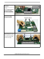
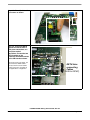
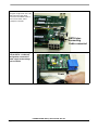
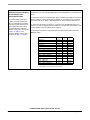
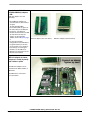
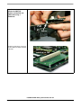
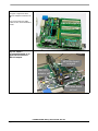
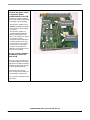
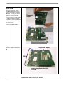
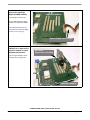
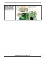
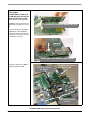
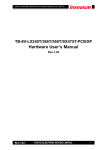
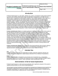
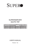
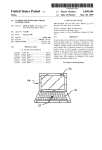
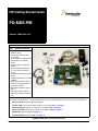
HW Getting Started Guide
PQ-MDS-PIB
January 2006: Rev. 0.4
Step 1: Check kit contents
1. PQ- MDS- PIB (Platform I/O
Board, or “PIB”)
2. Power cable extension with
on-off switch
3. 25 Pin IEEE 1284 Parallel cable
4. Serial cable 10cm D25M to
IDC10
5. Parallel cable 10cm D25M to
IDC26F
6. RJ45 to IDC8F Cable (2 pcs)
7. LC Loop back 62.5/125Fiber
(2 pcs)
8. USB Cable StndA Plug to MiniB
1Meter
9. USB Cable MiniA Plug to StndB
1.5Meter
10. PMC Board assembly spacers
11. AC/DC Power Supply 48V/2.7A
(Input 120-230VAC)
12. PQ- MDS- PIB Getting started
guide
13. PQ- MDS- PIB Board Errata
14. PQ- MDS- PIB Documentation
CD
3
12,13
11
2
14
6
8
9
7
1
4
5
10
The steps on the following pages describe how to connect various peripheral devices to the PIB, and how to configure the PIB
to work with them. Each device is sold separately. Instructions for working with them are found in their user documentation.
Processor Board (required): Step 2, on page 2
Configure PIB to work with the agent modules you are using: Step 3 on page 5
PMC-PCI Adaptors (optional: for using up to two agents): Step 4 on page 6
Expansion Adaptor (optional: for using up to four agents): Step 5, on page 9
USB Module (optional): Step 6, on page 12
Quad-OC3 Module (optional): Step 7, on page 13
PQ-MDS-PIB HW Getting Started Guide, Rev. 0.4
Freescale Semiconductor
Page 1 of 14
Step 2: Attach Processor
Board to PIB
Underside of
processor board
(MPC83xx processor board is sold
separately)
Step 2.a: Remove protective
covers from the 300-pin
connectors on the bottom
side of the Processor board
Step 2.b: Remove protective
covers from the 300-pin
connectors on the PIB.
Remove protective
covers by hand
Protective Covers
PIB
Step 2.c: Connect Processor
board to PIB board as shown.
Ensure a tight fit by pressing down
on the Processor board by hand
only until the pins engage
Press down to fasten
PQ-MDS-PIB HW Getting Started Guide, Rev. 0.4
Page 2 of 14
Freescale Semiconductor
Step 2.d: Manually fasten the
four screws as shown.
Step 2.e: If you wish GETH
signals to traverse either a
back plane connection, or a
front plane optical
connection, connect the two
GETH sockets on the
Processor board with sockets
on the PIB board as shown.
Note that if you do not do this, you
can still connect GETH cables
directly to the Processor board’s
sockets, if they are accessible in
your application’s configuration.
Processor Board on PIB
GETH
Sockets
GETH Interconnecting
Cables
(RJ45 to IDC8F)
PQ-MDS-PIB HW Getting Started Guide, Rev. 0.4
Freescale Semiconductor
Page 3 of 14
The figure at right shows one of the
GETH interconnecting cables
connected to the GETH socket on
the Processor board, and its
counterpart on the PIB.
Processor Board on PIB
GETH Interconnecting
Cable connected
Step 2.f: If you are working
with the PIB in a “table-top”
configuration, connect the
power supply to the voltage
input as shown.
Power
PQ-MDS-PIB HW Getting Started Guide, Rev. 0.4
Page 4 of 14
Freescale Semiconductor
Configure the I/O Expanders ( communication devices on the PIB) via the I2C block on the
Step 3: Use host chip on
processor board to configure MPC83xx chip. For a more detailed explanation of the I/O Expanders, see the PIB User’s
Manual.
PIB according to your
developmental needs
If you will be working with agent
modules, you must configure the
PIB to accomodate these modules
before these can be attached (see
table at right). Once this is done,
then install either the PMC-PCI
adaptors (if using up to two agents)
in Step 4 on page 6, or the
Expansion Adaptor (if using up to
four agents) in Step 5 on page 9.
The table below shows each communication option available: which PMC slot is used (for
PMC-PCI adaptors), whether the Expansion Adaptor is used, which bus is used (PCI1,
PCI2) and its size (32 vs. 64 bits). Note that there are values that must always be set.
The values must be written, via the I2C, to a register on the I/O Expander device. For
example, to connect an agent board to the PMC1 slot, using the PCI1 bus at 32 bits, write
the value 0xFFFF to the I2C address 0x26, register 2.
It is important to note that the values indicated in the first five lines of the table must
always be written.
Communication Option
1
I2C Addr
Reg #
Always set:
0x23
6
Value
0
Always set:
0x26
6
0x0034
Always set:
0x27
6
0
Always set:
0x23
2
0xFFFF
Always set:
0x27
2
0xFFEF
PCI1 - Expansion Adaptor 64 bit
0x26
2
0xFCFF
PCI1 - Expansion Adaptor 32 bit
0x26
2
0xF8FF
PCI1 - 64bit on PMC21
0x26
2
0xF4FF
PCI1 - PMC1 32bit
0x26
2
0xFFFF
PCI1 - PMC1 & PMC2 32bit
0x26
2
0xF7FF
PCI1 - PMC1, PMC2 & PMC3 32bit
0x26
2
0xF3FF
PCI1 - PMC1 & PMC2 32bit
PCI2 - PMC3 32bit
0x26
2
0xF5FF
PCI2 - PMC3 32bit
0x26
2
0xFDFF
PCI2 - PMC2 & PMC3 32bit
0x26
2
0xF9FF
If PCI1 can be 64 bits in size. This depends on the specific MPC83xx host
model. Refer to its User’s Manual for specifications.
PQ-MDS-PIB HW Getting Started Guide, Rev. 0.4
Freescale Semiconductor
Page 5 of 14
Step 4: Attach PMC-PCI
(PQ-MDS-PMCPCI) adaptors
to PIB
(PMC-PCI adaptors are sold
separately)
• Each PMC-PCI adaptor can
accommodate one PCI board as
an agent.
• To work with up to two
PCI-format boards as agents at
the same time (on two different
PCI buses), use PMC-PCI
modules to attach them to the PIB
• To work with more than two
agents, use the expansion
adaptor, shown in Step 5 on page
9.
• For the exact possible
configurations and combinations
of agent locations (not all slots
can be used for every situation),
bus name(s), host and agent
modules, see the PIB User’s
Manual or the relevant Processor
Board’s User’s Manual.
PMC-PCI adaptor (view from above)
PMC-PCI adaptor (view from below)
Step 4.a: Connect each
PMC-PCI adaptor as shown,
and press in firmly (by hand)
until it clicks in place.
Connect as shown
Tighten by hand
The PMC-PCI adaptors can be
inserted into the PMC1, PMC2, or
PMC3 slots.
The PMC0 slot is reserved for
non-PCI modules.
PMC0
PMC1
PMC2
PMC3
PQ-MDS-PIB HW Getting Started Guide, Rev. 0.4
Page 6 of 14
Freescale Semiconductor
Step 4.b: Insert spacers
between the PMC-PCI
adaptors and the PIB, and
tighten them using a
screwdriver.
PMC-PCI adaptor
PIB
Spacer
The figure at right shows a close-up
view of a PMC-PCI adaptor installed
on the PIB.
PMC-PCI adaptor
installed on PIB
PQ-MDS-PIB HW Getting Started Guide, Rev. 0.4
Freescale Semiconductor
Page 7 of 14
The figure at right shows three
PMC-PCI adaptors installed on the
PIB.
Proces
so
r Board
A processor board and a USB
module are also shown installed on
the PIB.
PMC-PCI adaptors
installed on PIB
USB module
Step 4.c: Insert a
PCI-compatible board as an
agent into the slot on the
PMC-PCI adaptor.
MPC83xx board
as agent
PMC-PCI
adaptor
MPC83xx board
as host
PQ-MDS-PIB HW Getting Started Guide, Rev. 0.4
Page 8 of 14
Freescale Semiconductor
Step 5: If you wish to use
more than two agents, attach
the expansion adaptor
(PQ-MDS-PCIEXP) to the PIB.
(the expansion adaptor, including
the riser cards and its own dedicated
power supply, is sold separately)
• The expansion adaptor is used
instead of the PMC-PCI modules
if more than two agent modules
are needed.
• The expansion adaptor can
accommodate up to four PCI
boards (working at the same
time, on the same bus) as agents.
• For the exact possible
configurations and combinations
of agent locations (not all slots
can be used for every situation),
bus name(s), host and agent
modules, see the PIB User’s
Manual or the relevant Processor
Board’s User’s Manual.
Platform I/O Board (PIB)
PMC0 slot
Riser card
(not installed)
PMC1
PMC2
Riser cards
(installed)
PMC3
Step 5.a: If using a module in
the PMC0 slot, insert riser
cards on PIB
These riser cards are used to raise
the expansion adaptor to the proper
height when a module is installed in
the PMC0 slot (the figures show this
slot with no module installed).
Insert the three riser cards as
shown, starting from the PMC3 slot,
and continuing to the PMC1 slot.
Press each riser card firmly in until it
clicks in place.
PQ-MDS-PIB HW Getting Started Guide, Rev. 0.4
Freescale Semiconductor
Page 9 of 14
Step 5.b: Connect expansion
adaptor to PIB
Connect the expansion adaptor
(PQ-MDS-PCIEXP) to the PIB as
shown. If no module is used in the
PMC0 slot, the riser cards are not
needed, as shown in the figure.
Expansion
adaptor
If a module (such as a USB module
or a QOC3 module) is installed in
the PMC0 slot, the riser cards must
be used (refer to Step 5.a on page
9 for instructions).
Press the PQ-MDS-PCIEXP in
firmly until it clicks in place.
Connect expansion
adaptor as shown
PMC0 slot
Platform I/O Board (PIB)
The figure at right shows an
expansion adaptor installed on the
PIB.
expansion adaptor
PIB
expansion adaptor installed
on PIB
PQ-MDS-PIB HW Getting Started Guide, Rev. 0.4
Page 10 of 14
Freescale Semiconductor
Step 5.c: Connect power
supply to the expansion
adaptor (PQ-MDS-PCIEXP).
expansion adaptor
Use the 20-pin connecter only.
This is a dedicated power supply,
included in the expansion adaptor
kit.
(Note that the PIB must also be
connected to its own power supply.
See Step 2.f on on page 4)
Power supply cord (20 pin)
Step 5.d: Insert a PCI-format
module(s) as an agent on the
expansion adaptor as shown
(MPC83xx board shown).
MPC83xx
Agent board installed
Up to four agent modules can be
inserted at any one given time.
PIB
expansion adaptor
PQ-MDS-PIB HW Getting Started Guide, Rev. 0.4
Freescale Semiconductor
Page 11 of 14
Step 6: If working with the
USB module, attach it to the
PIB and press in firmly (by
hand) until it clicks in place.
Connect as shown
Tighten by hand
USB
Module
(USB module is sold separately)
USB module can only be used in slot
PMC0.
PMC0 slot
PMC1
PMC2
PQ-MDS-PIB HW Getting Started Guide, Rev. 0.4
Page 12 of 14
Freescale Semiconductor
Step 7: If working with the
QOC3 module
(PQ-MDS-QOC3), attach it to
the PIB and press in firmly (by
hand) until it clicks in place.
(QOC3 module is sold separately)
The QOC3 can be connected to the
PMC0 and/or the PMC1 slot on the
PIB.
Use the metal spacers (provided in
the QOC3 kit) to hold the QOC3
Module in position on the PIB. The
metal spacers are optional, and can
be removed if necessary.
Position QOC3 Module above PMC slot
SW10 SW4
PMC1 slot
PMC0 slot
Press down until module snaps in place
The figure at right shows a QOC3
module installed on the PIB.
MPC83xx board
as agent
PQ-MDS-QOC3 module
installed on PIB
MPC83xx board
as host
PQ-MDS-PIB HW Getting Started Guide, Rev. 0.4
Freescale Semiconductor
Page 13 of 14
How to Reach Us:
Information in this document is provided solely to enable system and software implementers to use
Freescale Semiconductor products. There are no express or implied copyright licenses granted
hereunder to design or fabricate any integrated circuits or integrated circuits based on the information
USA/Europe/Locations Not Listed:
Freescale Semiconductor Literature Distribution Center in this document.
Freescale Semiconductor reserves the right to make changes without further notice to any products
P.O. Box 5405
herein. Freescale Semiconductor makes no warranty, representation or guarantee regarding the
Denver, Colorado 80217
suitability of its products for any particular purpose, nor does Freescale Semiconductor assume any
1-800-521-6274 or 480-768-2130
liability arising out of the application or use of any product or circuit, and specifically disclaims any
and all liability, including without limitation consequential or incidental damages. “Typical” parameters
Japan:
that may be provided in Freescale Semiconductor data sheets and/or specifications can and do vary
Freescale Semiconductor Japan Ltd.
in different applications and actual performance may vary over time. All operating parameters,
Technical Information Center
including “Typicals”, must be validated for each customer application by customer’s technical experts.
3-20-1, Minami-Azabu, Minato-ku
Freescale Semiconductor does not convey any license under its patent rights nor the rights of others.
Tokyo 106-8573, Japan
Freescale Semiconductor products are not designed, intended, or authorized for use as components
81-3-3440-3569
in systems intended for surgical implant into the body, or other applications intended to support or
sustain life, or for any other application in which the failure of the Freescale Semiconductor product
Asia/Pacific:
could create a situation where personal injury or death may occur. Should Buyer purchase or use
Freescale Semiconductor Hong Kong Ltd.
Freescale Semiconductor products for any such unintended or unauthorized application, Buyer shall
2 Dai King Street
indemnify and hold Freescale Semiconductor and its officers, employees, subsidiaries, affiliates, and
Tai Po Industrial Estate
distributors harmless against all claims, costs, damages, and expenses, and reasonable attorney
Tai Po, N.T., Hong Kong
fees arising out of, directly or indirectly, any claim of personal injury or death associated with such
852-26668334
unintended or unauthorized use, even if such claim alleges that Freescale Semiconductor was
negligent regarding the design or manufacture of the part.
Home Page:
www.freescale.com
Learn More: For more information about Freescale products, please visit www.freescale.com.
Freescale™ and the Freescale logo are trademarks of Freescale Semiconductor, Inc. All other
product or service names are the proerty of their respective owners.
© Freescale Semiconductor, Inc. 2006. All rights reserved.
PQ-MDS-PIB HW Getting Started Guide, Rev. 0.4
Page 14 of 14
Freescale Semiconductor