1
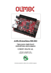
A13-OLinuXino-MICRO Open-source single-board mini-computer USER’S MANUAL Revision A, December 2012 Designed by OLIMEX Ltd, 2012 All boards produced by Olimex LTD are ROHS compliant OLIMEX© 2012 A13-OLinuXino-MICRO User's Manual DISCLAIMER © 2012 Olimex Ltd. Olimex®, logo and combinations thereof, are registered trademarks of Olimex Ltd. Other product names may be trademarks of others and the rights belong to their respective owners. The information in this document is provided in connection with Olimex products. No license, express or implied or otherwise, to any intellectual property right is granted by this document or in connection with the sale of Olimex products. The Hardware project is released under the Creative Commons Attribution-Share Alike 3.0 United States License. You may reproduce it for both your own personal use, and for commercial use. You will have to provide a link to the original creator of the project https://www.olimex.com on any documentation or website. You may also modify the files, but you must then release them as well under the same terms. Credit can be attributed through a link to the creator website: https://www.olimex.com The software is released under GPL. It is possible that the pictures in this manual differ from the latest revision of the board. The product described in this document is subject to continuous development and improvements. All particulars of the product and its use contained in this document are given by OLIMEX in good faith. However all warranties implied or expressed including but not limited to implied warranties of merchantability or fitness for purpose are excluded. This document is intended only to assist the reader in the use of the product. OLIMEX Ltd. shall not be liable for any loss or damage arising from the use of any information in this document or any error or omission in such information or any incorrect use of the product. This evaluation board/kit is intended for use for engineering development, demonstration, or evaluation purposes only and is not considered by OLIMEX to be a finished end-product fit for general consumer use. Persons handling the product must have electronics training and observe good engineering practice standards. As such, the goods being provided are not intended to be complete in terms of required design-, marketing-, and/or manufacturing-related protective considerations, including product safety and environmental measures typically found in end products that incorporate such semiconductor components or circuit boards. Olimex currently deals with a variety of customers for products, and therefore our arrangement with the user is not exclusive. Olimex assumes no liability for applications assistance, customer product design, software performance, or infringement of patents or services described herein. THERE IS NO WARRANTY FOR THE DESIGN MATERIALS AND THE COMPONENTS USED TO CREATE OLINUXINO. THEY ARE CONSIDERED SUITABLE ONLY FOR OLINUXINO. Page 2 of 30 OLIMEX© 2012 A13-OLinuXino-MICRO User's Manual Table of Contents DISCLAIMER............................................................................................................. 2 CHAPTER 1: OVERVIEW........................................................................................5 1. Introduction to the chapter.......................................................................................................5 1.1 Features.....................................................................................................................................5 1.2 Target market and purpose of the board.............................................................................. 6 1.3 Board variants..........................................................................................................................6 1.4 Organization.............................................................................................................................6 CHAPTER 2: SETTING UP THE OLINUXINO BOARD.....................................8 2. Introduction to the chapter.......................................................................................................8 2.1 Electrostatic warning...............................................................................................................8 2.2 Requirements........................................................................................................................... 8 2.3 Powering the board..................................................................................................................9 2.4 Prebuilt software....................................................................................................................10 2.5 Software instructions and available SD card images........................................................ 10 CHAPTER 3: A13-OLinuXino-MICRO BOARD DESCRIPTION..................... 11 3. Introduction to the chapter.....................................................................................................11 3.1 Layout (top view)...................................................................................................................11 CHAPTER 4: THE ALLWINNER A13 MICROCONTROLLER.......................12 4. Introduction to the chapter.....................................................................................................12 4.1 The microcontroller...............................................................................................................12 4.2 Block diagram........................................................................................................................ 14 CHAPTER 5: CONTROL CIRCUITY................................................................... 15 5. Introduction to the chapter.....................................................................................................15 5.1 Reset........................................................................................................................................15 5.2 Clock....................................................................................................................................... 15 5.3 Power supply circuit..............................................................................................................15 CHAPTER 6: CONNECTORS AND PINOUT......................................................16 6. Introduction to the chapter.....................................................................................................16 6.1 Communication with the A13............................................................................................... 16 6.1.1 USB communication.....................................................................................................................................16 6.1.2 UART1 interface...........................................................................................................................................16 6.2 SD/MMC slot..........................................................................................................................17 6.3 UEXT module.........................................................................................................................18 6.4 GPIO-1 (General Purpose Input/Output) 10pin connector...............................................19 6.5 GPIO-2 (General Purpose Input/Output) 40pin connector ..............................................19 6.6 LCD_CON 40pin connector .................................................................................................21 6.7 PWR Jack...............................................................................................................................22 Page 3 of 30 OLIMEX© 2012 A13-OLinuXino-MICRO User's Manual 6.8 Headphones and microphone connector..............................................................................22 6.9 VGA video connector.............................................................................................................23 6.10 Jumper description..............................................................................................................23 6.10.1 1.2V_E, 1.5V_E, 3.3V_E............................................................................................................................23 6.10.2 HOST_EN...................................................................................................................................................24 6.11 Additional hardware components...................................................................................... 24 CHAPTER 7: SCHEMATICS..................................................................................25 7. Introduction to the chapter.....................................................................................................25 7.1 Eagle schematic......................................................................................................................25 7.2 Physical dimensions...............................................................................................................27 CHAPTER 8: REVISION HISTORY AND SUPPORT........................................ 28 8. Introduction to the chapter.....................................................................................................28 8.1 Document revision................................................................................................................. 28 8.2 Board revision........................................................................................................................ 28 8.3 Useful web links and purchase codes................................................................................... 29 8.4 Product support..................................................................................................................... 30 Page 4 of 30 OLIMEX© 2012 A13-OLinuXino-MICRO User's Manual CHAPTER 1: OVERVIEW 1. Introduction to the chapter Thank you for choosing the OLinuXino single board computer from Olimex! This document provides a user’s guide for the Olimex OLinuXino board. As an overview, this chapter gives the scope of this document and lists the board’s features. The document’s organization is then detailed. The OLinuXino development board enables code development of applications running on the microcontroller A13, manufactured by Allwinner Technology from China. OLinuXino is an open-source, open-hardware project and all documentation is available to the customer. 1.1 Features • A13 Cortex A8 processor at 1GHz, 3D Mali400 GPU • 256 MB RAM (128Mbit x 16) • 5VDC input power supply, noise immune design • 1 USB Host • 1 USB OTG which can power the board • SD-card connector for booting Linux or Android image • VGA video output – 800 x 600 maximum resolution • LCD signals available on connector so you still can use LCD if you diasble VGA/HDMI • Audio output • Microphone input pads (no connector) • 1 User key • 4 Mount holes • UEXT connector for connecting addtional UEXT modules like Zigbee, Bluetooth, relays, etc • GPIO connector with 68/74 pins and these signals : 17 for adding NAND flash; 22 for connecting LCDs; 20+4 including 8 GPIOs which can be input, output, interrupt sources; 3x I2C; 2x UARTs; SDIO2 for connectinf SDcards and modules; 5 system pins: +5V, +3.3V, GND, RESET, NMI • (Optional low cost 7" or 4.8'' LCD with/without touchscreen) Page 5 of 30 OLIMEX© 2012 A13-OLinuXino-MICRO User's Manual 1.2 Target market and purpose of the board The boards from the OLinuXino family are powerful and easy to setup. They are suitable for embedded programming enthusiasts, Linux and Android gadget fans and also professionals (since its low cost makes it very good solution for application orientated embedded systems). The main usage of the board is software embedded development without the urge of understanding perfectly the hardware. The strong points of the boards are the processor speed, the mobility of the board and the low ratio price to productivity. A13-OLinuXino-MICRO aims at the lowest possible cost while maintaining the key OLinuXino features. It is suitable for cases when a number of boards are used. It is suitable for different Linux distributions. Customers have full access to the technical documentation of the board. The software is released under General Purpose License and the board is considered open-hardware. 1.3 Board variants There are two major board variants. According to the names: A13-OLinuXino and A13OLinuXino-MICRO. The base model has also two flavors: A13-OLinuXino and A13-OLinuXino-MICRO-WIFI. The first one is the base model that goes without any operating system image on board, while the second has two additional components – a WIFI module on the board and NAND memory with stored Android image. The A13-OLinuXino-MICRO is the other less populated but cheaper board in the family. It also lacks Android out-of-the-box. 1.4 Organization Each section in this document covers a separate topic, organized as follow: – Chapter 1 is an overview of the board usage and features – – Chapter 2 provides a guide for quickly setting up the board and software notes Chapter 3 contains the general board diagram and layout – Chapter 4 describes the component that is the heart of the board: the A13 – Allwinner processor Page 6 of 30 OLIMEX© 2012 A13-OLinuXino-MICRO User's Manual – Chapter 5 is an explanation of the control circuitry associated with the microcontroller to reset. Also shows the clocks on the board Chapter 6 covers the connector pinout, peripherals and jumper description – – Chapter 7 provides the schematics Chapter 8 contains the revision history, useful links and support information – Page 7 of 30 OLIMEX© 2012 A13-OLinuXino-MICRO User's Manual CHAPTER 2: SETTING UP THE OLINUXINO BOARD 2. Introduction to the chapter This section helps you set up the OLinuXino development board for the first time. Please consider first the electrostatic warning to avoid damaging the board, then discover the hardware and software required to operate the board. The procedure to power up the board is given, and a description of the default board behavior is detailed. 2.1 Electrostatic warning OLinuXino is shipped in a protective anti-static package. The board must not be exposed to high electrostatic potentials. A grounding strap or similar protective device should be worn when handling the board. Avoid touching the component pins or any other metallic element. 2.2 Requirements In order to set up the OLinuXino optimally, the following items are required: - 5V, 5W required (5V @ 1A) – for optimal power - LCD (preferably with touchscreen panel) display for the LCD_CON OR TV monitor with RGB port (or suitable connector) – note the maximum display resolution should be 800x600 - USB hub (for splitting the USB) – else you will be unable to connect your USB devices - A USB mouse – if you use touchscreen LCD you might skip the mouse Additional items include: - USB keyboard – for convenience with text input - USB-SERIAL-CABLE-F – for serial communication with UART1 connector (note that it has to be female) - USB-MINI-CABLE – for connecting with the USB OTG and being able to firmware update to power A13-OLinuXino-MICRO - Wireless internet connectivity or USB modem – for browser access and access to the Android market Page 8 of 30 OLIMEX© 2012 A13-OLinuXino-MICRO User's Manual Some of the suggested items can be purchased by Olimex, for instance: SY0605E - power supply adapter 5V/1A for A13-OLinuXino-MICRO USB-SERIAL-CABLE-F - USB serial console cable female USB-MINI-CABLE – standard USB type A to USB type mini cable A 7'' LCD display with optional touch screen panel is available for purchase also: https://www.olimex.com/Products/OLinuXino/A13/A13-LCD7/ https://www.olimex.com/Products/OLinuXino/A13/A13-LCD7-TS/ 2.3 Powering the board There are two possible ways of powering A13-OLinuXino-MICRO – via external supply using the power jack, or via the USB OTG connector. Depending on your preferred way of powering A13OLinuXino-MICRO you might need additional hardware. The preferred way of powering board is via the PWR jack with 5Vdc with a power of 5W (e.g. 5Vx1A ). This will make the board fully powered and able to power most peripherals connected to it. The board can also be powered by the USB OTG connector (mini USB standard) but the power provided by a standard USB is not enough to power a lot of peripherals - either a LCD (connected tothe LCD_con) or USB peripherals (connected to the USB type B) but not to power both. If you still wish to use USB power there are is the option to use adapter 2xUSB type A to 1xUSB type mini. If you have a standard LCD display connected to LCD_con, Android and WIFI running the typical consumption is around 450mA depending on the current load. While the board is in stand-by mode it consumes a minimum of 70mA. All the three approximate values above were taken when I applied 5V to the board. For the European customers we sell a power supply adapter 1V/0.5A – SY0605E. We also sell USB type A to USB mini cables if you lack such. Page 9 of 30 OLIMEX© 2012 A13-OLinuXino-MICRO User's Manual 2.4 Prebuilt software Note that the A13-OLinuXino and A13-OLinuXino-MICRO lack NAND memory and WIFI and there isn't OS uploaded on the shipped boards. So far we have been successful in using Debian booting from SD card with both of the boards. The same can't be said for booting Android from SD card. 2.5 Software instructions and available SD card images This can vary depending on what the owner of the board want to achieve. Good collection on information on the subject can be found at the following WIKI articles: https://www.olimex.com/wiki/A13-OLinuXino-MICRO https://www.olimex.com/wiki/A13-OLinuXino Other good sources are: 1) the Wordpress site where a lot of side projects are published and explained: http://olimex.wordpress.com/ 2) the Olimex forum in its A13 section https://www.olimex.com/forum/ Page 10 of 30 OLIMEX© 2012 A13-OLinuXino-MICRO User's Manual CHAPTER 3: A13-OLinuXino-MICRO BOARD DESCRIPTION 3. Introduction to the chapter Here you get acquainted with the main parts of the board. Note the names used on the board might differ from the names used below to describe them. For the actual names check the A13OLinuXino-MICRO board itself. 3.1 Layout (top view) The picture above shows the initial revision B of A13-OLinuXino-MICRO. Page 11 of 30 OLIMEX© 2012 A13-OLinuXino-MICRO User's Manual CHAPTER 4: THE ALLWINNER A13 MICROCONTROLLER 4. Introduction to the chapter In this chapter is located the information about the heart of OLinuXino – its microcontroller. The information is a modified version of the datasheet provided by its manufacturers. 4.1 The microcontroller CPU/GPU ARM Cortex-A8 Core 32KB D-Cache/ 32KB I-Cache 256KB L2 Cache Mali-400 3-D Engine VPU HD Video Decoding 1920*1080@30fps Support H.264, H.263, VC1, Mpeg1/2/4 Divx 3/4/5/6, Xvid, VP6/8, AVS etc HD Video Encoding Support encoding in H.264 format Up to 1920*1080 at 30fps DPU LCD Interfaces: CPU, RGB Memory DDR2/DDR3: Up to 533MHz 16 bits Data Bus Memory capacity up to 512MB MLC/TLC/SLC/EF-NAND 2 flash chips, ECC 64-bit Support NAND of 5xnm, 4xnm, 3xnm, 2xnm Support NADN of Samsung, Toshiba, Hynix Peripherals USB2.0 OTG, USB2.0 HOST Page 12 of 30 OLIMEX© 2012 A13-OLinuXino-MICRO User's Manual (OHCI/EHCI) SD Card V.3.0, eMMC V.4.2 SPI, TWI and UART integrated Audio Codec CSI R-TP Controller 4-wire resistive TP interface 2 points and gesture detection Boot Devices NAND Flash SPI Nor Flash SD Card USB Powerful Acceleration Graphic (3D, Mali400 MP) VPU (1080P) APU E-Reader Ultra-low System Power Consumption 15~20% lower than competitors Smart Backlight: auto adjust backlight acc. to the image display Package eLQFP176 More information can be found on Allwinner's web site at the following web-address: http://www.allwinnertech.com/product/A13.html Page 13 of 30 OLIMEX© 2012 A13-OLinuXino-MICRO User's Manual 4.2 Block diagram The block diagram is taken from Allwinner's datasheet. Page 14 of 30 OLIMEX© 2012 A13-OLinuXino-MICRO User's Manual CHAPTER 5: CONTROL CIRCUITY 5. Introduction to the chapter Here you can find information about reset circuit and quartz crystals locations, the power supply circuit is discussed. 5.1 Reset The reset line is handled by MCP130T-300-I. This is a voltage supervisory device designed to keep a microcontroller in reset until the system voltage has reached the proper level and stabilized. It also operates as protection from brown-out conditions when the supply voltage drops below a safe operating level. The reset goes to processor pin 195. The reset circuit is connected to button RESET, which means pressing RESET would perform a hardware reset on the board. 5.2 Clock 24 MHz quartz crystal Q1 is connected to pins 91 and 92 of the A13 processor. 5.3 Power supply circuit The 5V power supply is handled by three voltage regulators for the 1.2V, 1.5V and 3.3V power lines. The board can be powered from the USB_OTG connector. Note that powering from the USB limits the current available for peripheral devices (like mouse, keyboard, LCD display, UEXT modules, etc.). Page 15 of 30 OLIMEX© 2012 A13-OLinuXino-MICRO User's Manual CHAPTER 6: CONNECTORS AND PINOUT 6. Introduction to the chapter In this chapter are presented the connectors that can be found on the board all together with their pinout and notes about them. Jumpers functions are described. Notes and info on specific peripherals are presented. Notes regarding the interfaces are given. 6.1 Communication with the A13 The chip has a built-in bootloader but the communication for this type of board is not very useful via the mini USB – the board lacks NAND. However, there is a second option which is the male UART1 connector capable of delivering some information on the COM port of your computer. You can use USB-SERIAL-CABLE-F with the UART1 interface allowing you to connect to an USB port. Note that we haven't still managed to run Android from the SD card so it might require tweaking the image to be able to do it. We have had a successful Debian booting from SD card. 6.1.1 USB communication There is only one USB type A host wired to a USB-controller. This means that an external USB hub is required to ensure you have enough room for all USB devices you might want to use (keyoard, mouse, etc). 6.1.2 UART1 interface The UART interface might be used for COM communication. You can use our USB-SERIALCABLE-F for debugging via the UART1 or UART0. Note that in both cases the connectors and the signals are named at the bottom of the board. Note that UART0 has only pinholes available, while UART1 has male connectors. Consider the below table when connecting the USB-SERIAL-CABLE-F according to the wire color Page 16 of 30 OLIMEX© 2012 A13-OLinuXino-MICRO User's Manual code of the cable - GND=BLUE, RX(INPUT)=GREEN, TX(OUTPUT)=RED; note that RX of the cable has to connect to TX of the board and vice versa. UART0 Pin # Signal Name UART1 Processor Pin # Pin # Signal Name Processor Pin # 1 3.3V - 1 3.3V - 2 SDC0_SCK 110 2 UART1_TX 152 3 SDC0_DATA3 112 3 UART1_RX 151 4 GND - 4 GND - Note that UART0 is multiplexed with the SD card. 6.2 SD/MMC slot The microSD card slot is a standard 8pin connector. The SD card can be used for booting the operating system for A13-OLinuXino-MICRO. It is suggested to have an SD card with a proper Linux/Android image especially since you have ordered a board from the A13 family without built-in memory. We have tested a number of microSD cards on the OLinuXino boards and all of them worked fine regardless manufacturer or capacity. However, keep in mind that some of the lower quality microSD cards might draw too much current from the slot which might cause power-state problems. If you suspect the microSD card is causing problems please try using another one of better quality for better results. microSD card connector Pin # Signal Name Processor Pin # 1 DAT2/RES 113 2 SDC0_DATA3 112 3 SDC0_CMD 111 Page 17 of 30 OLIMEX© 2012 A13-OLinuXino-MICRO User's Manual 4 VDD - 5 SDC0_SCK 110 6 VSS - 7 SDC0_DATA0 108 8 SDC0_DATA1 107 When removing the card, please make sure that you release it from the connector by pushing and NOT by pulling the card directly (this can damage both the connector and the microSD card). 6.3 UEXT module A13-OLinuXino-MICRO has an UEXT connector and can connect with Olimex's UEXT modules. For more information on UEXT please visit: https://www.olimex.com/Products/Modules/UEXT/resources/UEXT.pdf UEXT connector Pin # Signal Name Processor Pin # 1 3.3V - 2 GND - 3 UART1_TX 152 4 UART1_RX 151 5 TWI2_SCK 161 6 TWI2_SDA 160 7 SPI2_MISO 117 8 SPI2_MOSI 116 9 SPI2_CLK 115 10 SPI2_CS0 114 The UEXT pinout is also printed at the bottom of the board under the connector. Page 18 of 30 OLIMEX© 2012 A13-OLinuXino-MICRO User's Manual 6.4 GPIO-1 (General Purpose Input/Output) 10pin connector The GPIO connector numbers are printed at the bottom of the board for your convenience. GPIO-1 Pin # Signal Name Processor Pin # 1 5V - 2 GND - 3 3.3V - 4 GND - 5 RESET_N 159 6 NMI_N 158 7 PIN0 - 8 PIN3 - 9 PIN1 - 10 PIN2 - PIN0, PIN1, PIN2 and PIN3 are connected to the power regulator module AXP209. 6.5 GPIO-2 (General Purpose Input/Output) 40pin connector The GPIO pins are led out on a separate 40pin connecter. They allow the user to attach additional hardware, check readings or perform hardware debug. The GPIO-2 connector numbers are printed at the bottom of the board for your convenience. Page 19 of 30 OLIMEX© 2012 A13-OLinuXino-MICRO User's Manual GPIO-2 connector GPIO Pin# Signal Name Processor pin# GPIO Pin# Signal Name Processor pin# 1 5V - 2 GND - 3 3.3V - 4 GND - 5 PIN4/TWI0-SCK 101 6 PIN39/USBH_EN 14 7 PIN5/TWI0-SDA 102 8 PIN38/VGA_DIS 13 9 PIN6/PW0 103 10 PIN37/LED1 12 11 PIN7 150 12 PIN36 125 13 PIN8 104 14 PIN35 124 15 PIN9 10 16 PIN34 123 17 PIN10/TWI1-SCK 105 18 PIN33 122 19 PIN11/TWI1-SDA 106 20 PIN32 121 GPIO Pin# Signal Name Processor pin# GPIO Pin# Signal Name Processor pin# 21 PIN12/NWE 8 22 PIN31 120 23 PIN13/NALE 7 24 PIN30 119 25 PIN14/NCLE 6 26 PIN29 118 27 PIN15/NCE1 3 28 PIN28/NDQS 162 29 PIN16/NCE0 2 30 PIN27/NDQ7 165 31 PIN17/NRE 1 32 PIN26/NDQ6 166 33 PIN18/NRB0 176 34 PIN25/NDQ5 167 35 PIN19/NRB1 175 36 PIN24/NDQ4 168 37 PIN20/NDQ0 174 38 PIN23/NDQ3 170 39 PIN21/NDQ1 172 40 PIN22/NDQ2 171 Page 20 of 30 OLIMEX© 2012 A13-OLinuXino-MICRO User's Manual 6.6 LCD_CON 40pin connector The LCD_CON pins are led out on a separate 40pin connecter for the ease of connecting an LCD. We have tested the ability of the board to interact with such a display. They allow the user to attach additional hardware, check readings or perform hardware debug. The LCD_CON connectors connector numbers are print at the bottom of the board for your convenience. LCD_CON connector GPIO Pin# Signal Name Processor pin# GPIO Pin# Signal Name Processor pin# 1 5 - 2 GND - 3 3.3 - 4 GND - 5 LCD_D18 135 6 LCD_D18 135 7 LCD_D18 135 8 LCD_D19 134 9 LCD_D20 133 10 LCD_D21 132 11 LCD_D22 131 12 LCD_D23 130 13 LCD_D10 141 14 LCD_D10 141 15 LCD_D10 141 16 LCD_D11 140 17 LCD_D12 139 18 LCD_D13 138 19 LCD_D14 137 20 LCD_D15 136 21 LCD_D2 148 22 LCD_D2 148 23 LCD_D2 148 24 LCD_D3 147 25 LCD_D4 146 26 LCD_D5 145 27 LCD_D6 144 28 LCD_D7 143 Page 21 of 30 OLIMEX© 2012 A13-OLinuXino-MICRO User's Manual 29 LCD_HSYNC 127 30 LCD_VSYNC 126 31 LCD_CLK 129 32 LCD_DE 128 GPIO Pin# Name Processor pin# GPIO Pin# Name Processor pin# 33 PIN7 150 34 PIN8 104 35 PIN9 10 36 PIN6/PWM0 109 37 TPX1 89 38 TPX2 87 39 TPY1 90 40 TPY2 88 6.7 PWR Jack The power jack used is the typical 2.5mm one used by Olimex in most of our products. You should provide 5 volts @ 1A maximum to the board. Pin # Signal Name 1 Power Input 2 GND More info about the power supply can be found in chapter 5 of this manual 6.8 Headphones and microphone connector Standard headphone jack and dual pins for microphone are mounted for the audio out/in interfacing. Microphone/Audio out connector Pin# SIGNAL NAME Processor Pin# 2 L channel 74 3 R channel 78 5 HPCOM GND pins The headphones resistance is 32 Ohms! The mic pads are connected to pins 84 and 85 of the A13 chip. Note that there isn't MIC jack mounted. Page 22 of 30 OLIMEX© 2012 A13-OLinuXino-MICRO User's Manual 6.9 VGA video connector The female DB15 connector is used for video output on a monitor. At the moment the maximum achieved resolution is 800x600 due to limited maximum frequency and the lack of integrated video controller in the chip. VGA connector GPIO Pin# Signal Name GPIO Pin# Signal Name 1 VGA_R 2 VGA_G 3 VGA_B 4 Not Connected 5 GND 6 GND 7 GND 8 GND 9 GND 10 GND 11 Not Connected 12 Not Connected 13 VGA_HSYNC 14 VGA_VSYNC 15 Not Connected 16 Not Connected 6.10 Jumper description Please note that all the jumpers on the board are SMD type. If you feel insecure of your soldering/cutting technique it is better not to try to adjust the jumpers. 6.10.1 1.2V_E, 1.5V_E, 3.3V_E These three jumpers provide test pads during production and debugging. They are You can check the supply voltages. It is not recommended to change their default positions. The default positions are closed. Page 23 of 30 OLIMEX© 2012 A13-OLinuXino-MICRO User's Manual 6.10.2 HOST_EN This jumper allows to control the power line on the USB_HOST. If it is open it is disconnected from the USB_HOST connector and the devices are always powered. If it is closed it is connected to the processor and can be controlled when to power via software means. Default positions is open. 6.11 Additional hardware components The components below are mounted on OLinuXino but are not discussed above. They are listed here for completeness: UBOOT button – used to enter bootloader mode Reset button – used to reset the board 256GB (128Mbit x 16) DDR3 SDRAM – the exact memory used in the first revisions of the board is HYNIX H5TQ2G63BFR LED1 + PWR_LED – GPIO LED + power-on LED Page 24 of 30 OLIMEX© 2012 A13-OLinuXino-MICRO User's Manual CHAPTER 7: SCHEMATICS 7. Introduction to the chapter In this chapter are located the schematics describing logically and physically A13-OLinuXinoMICRO. 7.1 Eagle schematic OLinuXino schematic is visible only for reference here. You can also find it on the OLinuXino's GitHub repository: https://github.com/OLIMEX/OLINUXINO. They are located in HARDWARE section. You are allowed to view and edit the schematics as long you keep them free and you mention at least the source address (e.g. https://www.olimex.com), as according to Creative Commons Attribution-Share. The EAGLE schematic is situated on the next page for quicker reference. Page 25 of 30 OLIMEX© 2012 3.3V 1.4V_CPU 1.4V_INT A13-OLinuXino-MICRO User's Manual 1.5V 2Gb DDR3 SDRAM (128Mx16) A13-OLinuXino-MICRO_rev_B 3.0VA U1 86 C65 1nF TPX1 C69 1nF TPY1 C70 1nF TPX2 C71 1nF TPY2 89 90 87 88 TPX1 TPY1 TPX2 TPY2 PIN4/TWI0-SCK PIN5/TWI0-SDA PIN6/PWM0 PIN7 PIN8 PIN9 PIN10/TWI1-SCK PIN11/TWI1-SDA TWI2_SCK TWI2_SDA 101 102 103 150 104 10 105 106 161 160 PIN12/NWE PIN13/NALE PIN14/NCLE PIN15/NCE1 PIN16/NCE0 PIN17/NRE PIN18/NRB0 PIN19/NRB1 PIN20/NDQ0 PIN21/NDQ1 PIN22/NDQ2 PIN23/NDQ3 PIN24/NDQ4 PIN25/NDQ5 PIN26/NDQ6 PIN27/NDQ7 PIN28/NDQS 8 7 6 3 2 1 176 175 174 172 171 170 168 167 166 165 162 NC PE0/CSI_PCLK/SPI2_CS0/EINT14 PE1/CSI_MCLK/SPI2_CLK/EINT15 PE2/CSI_HSYNC/SPI2_MOSI PE3/CSI_VSYNC/SPI2_MISO PE4/CSI_D0/SDC2_D0 PE5/CSI_D1/SDC2_D1 PE6/CSI_D2/SDC2_D2 PE7/CSI_D3/SDC2_D3 PE8/CSI_D4/SDC2_CMD PE9/CSI_D5/SDC2_CLK PE10/CSI_D6/UART1_TX PE11/CSI_D7/UART1_RX PB0/TWI0-SCK PB1/TWI0-SDA PB2/PWM/SPI2_MOSI/EINT16 PB3/IR_TX/SPI2_MISO/EINT17 PB4/IR_RX/EINT18 PB10/SPI2_CS1/EINT24 PB15/TWI1_SCK PB16/TWI1_SDA PB17/TWI2_SCK PB18/TWI2_SDA PC0/NWE/SPI0_MOSI PC1/NALE/SPI0_MISO PC2/NCLE/SPI0_CLK PC3/NCE1/SPI0_CS0 PC4/NCE0 PC5/NRE PC6/NRB0/SDC2_CMD PC7/NRB1/SDC2_CLK PC8/NDQ0/SDC2_D0 PC9/NDQ1/SDC2_D1 PC10/NDQ2/SDC2_D2 PC11/NDQ3/SDC2_D3 PC12/NDQ4/SDC2_D4 PC13/NDQ5/SDC2_D5 PC14/NDQ6/SDC2_D6 PC15/NDQ7/SDC2_D7 PC19/NDQS PF0/SDC0_D1/JTAG_TMS PF1/SDC0_D0/JTAG_TDI PF2/SDC0_CLK/UART0_TX PF3/SDC0_CMD/JTAG_TDO PF4/SDC0_D3/UART0_RX PF5/SDC0_D2/JTAG_TCK 1.2V_E 2.2uH/1.5A/DCR<0.1R/CD32 10uF/6.3V 1nF SD0CARD-DETECT USB0-VBUSDET USB0-IDDET R2 UART1_TX UART1_RX PIN37/LED1 PIN38/VGA_DIS PIN39/USBH_EN USB0-DRV U4A G FET4 P3 D S R38 10k P4 Y1 Y2 Y3 Y4 RESET_N R18 R22 D2 17.8k/1% 8.66k/1% LCD_D10 LCD_D11 VGA_CTRL BAT54S R25 R28 R31 R34 3.3V 9 7 5 3 1 3 5 7 9 11 13 15 17 19 21 23 25 27 29 31 33 35 37 39 LCD_D10 LCD_D12 LCD_D14 LCD_D2 LCD_D4 LCD_D6 LCD_HSYNC LCD_CLK PIN7 PIN9 TPX1 TPY1 1 SDC0_CMD RM12G2 RM12G3 RM12G1 FET1 BSS138 SDC0_DATA0 SDC0_DATA1 SDC0_DATA2 R0 R2 R4 R6 G0 G2 G4 G6 B0 B2 B4 B6 R1 R3 R5 R7 G1 G3 G5 G7 B1 B3 B5 B7 H SYNC VSYN C CLK DE L/R U/D PW RE BKL X1 X2 Y1 Y2 6 4 5 7 8 1 10 12 C73 22uF/6.3V SDC0_SCK SDC0_DATA0 SDC0_DATA1 SDC0_DATA2 L1 CL470nH/0805/1.76R/250mA R19 R23 D3 17.8k/1% 8.66k/1% 9 7 5 3 2 4 6 8 LCD_D2 LCD_D3 VGA_CTRL 1 3.3V BAT54S R26 4.32k/1% R29 2.2k/1% R32 1.05k/1% R35 549R/1% 3.3V G 10 GND LCD_D19 LCD_D21 LCD_D23 LCD_D11 LCD_D13 LCD_D15 LCD_D3 LCD_D5 LCD_D7 LCD_VSYNC LCD_DE PIN8 PIN6/PWM0 TPX2 TPY2 SN74ALV C244 A1 A2 A3 A4 Y1 Y2 Y3 Y4 +5V 11 13 15 17 19 FET2 BSS138 R20 R24 D4 Y1 Y2 Y3 Y4 BAT54S R27 R30 R33 R36 3.3V 9 7 5 3 G 100nF VGA 17.8k/1% 8.66k/1% 3.3V SN74ALV C244 A1 A2 A3 A4 10 GND R39 1k/1% 18 16 14 12 G U6B LCD_D4 LCD_D5 LCD_D6 LCD_D7 20 U5PWR VCC 51R VSS VDD CLK/SCLK DAT0/DO DAT1/RES DAT2/RES VGA_R VGA_G U6A 18 16 14 12 SN74ALVC244 Y1 Y2 Y3 Y4 6 8 10 12 14 16 18 20 22 24 26 28 30 32 34 36 38 40 MICRO_SD+CP 100nF C85 R40 1k/1% LCD_HSYNC R6 "N "- MOS Y1 Y2 Y3 Y4 A1 A2 A3 A4 19 51R 3.3V GND 4 BH40S SD0CARD-DETECT G 11 13 15 17 +5V 20 U4PWR VCC 5.0V GND 2 R14 NA(1M) SD SDC0_DATA3 SDC0_CMD 2 CD/DAT3/CS C72 22uF/6.3V 3 CMD/DI R15 10k RM12G4 SN74ALVC244 A1 A2 A3 A4 U5B LCD_D12 LCD_D13 LCD_D14 LCD_D15 R9 LCD_CON LCD_D18 LCD_D20 LCD_D22 R56 10k 3.3V 4.32k/1% 2.2k/1% 1.05k/1% 549R/1% 1 k/1% 0R 0R(Board_Mounted) 1 00 nF 10 0n F 1 00 nF 22 uF/6.3V 1 00 nF 10 0n F 1 00 nF 10 0n F 1 00 nF LCD EXTENSION RA1206_(4X0603)_4B8_100K 2 4 6 8 R 11 24 0R /1 % J1 J9 L1 L9 M7 T7 3.3V +5V RA1206_(4X0603)_4B8_100K U5A G 10 GND 4.32k/1% 2.2k/1% 1.05k/1% 549R/1% VGA_B +5V +5V 20 U6PWR VCC C86 D5 BAT54S VGA_DB15-F_1 VGA_DB15-F_2 VGA_DB15-F_3 VGA_DB15-F_13 VGA_DB15-F_14 VGA_DB15-F_5 VGA_DB15-F_6 VGA_DB15-F_7 VGA_DB15-F_8 VGA_DB15-F_10 D6 BAT54S " N "-MO S VGA_HSYNC VGA_VSYNC 5 HOST_EN 1 2 4 U9 SY6280 1 RESET IN OUT EN ISET VCC 2 L9 1 R59 13k/1% 1 FB0805/600R/2A 3 2 R61 NA 10uF/6.3V GND USB-OTG C104 100nF UDM1 2 UDP1 3 4 USB0-DRV USB0-VBUSDET U12 SY6280 +5V USB_HOST 5 SHIELD USB_A L6 FB0805/600R/2A 4 IN EN OUT ISET 3 Iset = 6800/R68 R68 13k/1% Iset = 523mA R57 47k R58 100k/1% Iset = 6800/R59 Iset = 523mA C95 USB_OTG L7 FB0805/600R/2A 1 +5V_OTG_PWR UDM0 UDP0 USB0-IDDET GND1 GND2 10k VBUS DD+ ID GND USB-OTG L8 USB R60 PIN39/USBH_EN U13 MCP130T-300I/TT T 1107A(6x3.8x2.5mm) NC NC NC NC NC NC GND3 GND4 3.3V 3 51R 18 16 14 12 100nF C84 C98 R52 VSSQ VSSQ VSSQ VSSQ VSSQ VSSQ VSSQ VSSQ VSSQ MicroSD HN1X4 SN74ALVC244 A1 A2 A3 A4 Open R50 10k(NA) VREFDQ H1 3.3V 3.3V USB-HOST +5V 3.3V 3.3V RESET 1.5V M8 10 0n F 22k/1% ZQ L8 VREFCA Close C94 R46 DDR3_ODT BH40S 4 G LCD_VSYNC R5 C93 47pF C54 C89 + 5 C 92 FB GND SY8008C(AA)C 2 22uF/6.3V EN R 42 LX 1 C91 2 IN 3 Y1 Y2 Y3 Y4 U4B D7 1N5819/SS14 3.3V_E 2.2uH/1.5A/DCR<0.1R/CD32 100k/1% 22uF/6.3V C88 1 L5 U8 22uF/6.3V 4 3.0VA NA +5V 1 19 3.3V 22uF/6.3V 3.3k/1% DQS0 DQS0_N K1 ODT BH10S SN74ALVC244 A1 A2 A3 A4 11 13 15 17 LCD_D20 LCD_D21 LCD_D22 LCD_D23 R 44 2.2k 22pF R41 V GA _CTRL BSS138 2 22uF/6.3V GND 2 4 6 8 LCD_D18 LCD_D19 Close 22uF/6.3V C81 R16 1k/1% C8 3 5 SY8008C(AA)C 1 R 37 3 C82 FB 22uF/6.3V LX EN "N "-MO S P5 1.5V_E 2.2uH/1.5A/DCR<0.1R/CD32 IN 4.99k/1% C80 22uF/6.3V U7 DQSL F3 G3 #DQSL 2 GPIO-2 4 PIN39/USBH_EN 6 8 PIN38/VGA_DIS PIN37/LED1 10 12 PIN36 PIN35 14 16 PIN34 PIN33 18 20 PIN32 PIN31 22 24 PIN30 PIN29 26 28 PIN28/NDQS PIN27/NDQ7 30 32 PIN26/NDQ6 PIN25/NDQ5 34 36 PIN24/NDQ4 38 PIN23/NDQ3 40 PIN22/NDQ2 1 3 5 7 9 11 13 15 17 19 21 23 25 27 29 31 33 35 37 39 +5V 3.3V PIN4/TWI0-SCK PIN5/TWI0-SDA PIN6/PWM0 PIN7 PIN8 PIN9 PIN10/TWI1-SCK PIN11/TWI1-SDA PIN12/NWE PIN13/NALE PIN14/NCLE PIN15/NCE1 PIN16/NCE0 PIN17/NRE PIN18/NRB0 PIN19/NRB1 PIN20/NDQ0 PIN21/NDQ1 NA(HN1X4) 3.3V 1 UART1 2 UART1_TX 3 UART1_RX 3.3V UART1-TX UART1-RX GND 51R LCD_DE NA PIN38/VGA_DIS VDDQ VDDQ VDDQ VDDQ VDDQ VDDQ VDDQ VDDQ VDDQ DQM1 DQM0 DQS1 DQS1_N 2 GPIO-1 4 6 NMI_N 8 10 1 3 5 240R/1% 7 9 RESET_N R13 SDC0_SCK SDC0_DATA3 2 3 4 CLK CLKN CKE H5TQ2G63BFR 3.3V 1 UART0 WEN CASN RASN NA DMU D3 E7 DML GPIO EXTENSION +5V 3.3V SD0CARD-DET ECT 47k B1 B9 D1 D8 E2 E8 F9 G1 G9 C55 3.3V Rb 1.5V R1 SDC0_DATA1 SDC0_DATA0 SDC0_SCK SDC0_CMD SDC0_DATA3 SDC0_DATA2 SVREF DDR3_RST T2 L2 L3 K3 J3 C1 00 22pF R21 R72 R73 C79 C 24 C2 5 C 26 C2 7 C 28 C2 9 C 30 C3 1 C 32 107 108 110 111 112 113 P7 2.2uH/1.5A/DCR<0.1R/CD32 C78 C43 100nF 240R/1% BA0 BA1 BA2 C7 DQSU #DQSU B7 + C 10 1 Ra L4 +5V RA0805_(4X0402)_22R A1 A8 C1 C9 D2 E9 F1 H2 H9 1.5V M2 N8 M3 CK J7 K7 #CK CKE K9 NA (100nF) GND +5V 2 22R 22R 22R 22R 22R 22R #RESET #CS #WE #CAS #RAS VSS VSS VSS VSS VSS VSS VSS VSS VSS VSS VSS VSS C87 C75 1.5k/1% 1 RA0805_(4X0402)_22R 3.3V UART0-TX UART0-RX GND 1.4V_INT P6 C7 7 5 FB Close 22uF/6.3V EN Vout=0.6*(1+Ra/Rb) 4 RA0805_(4X0402)_22R UART L3 2 C76 LX 1 R 17 3 2k/1% IN 22uF/6.3V C74 22uF/6.3V U3 SY8008C(AA)C +5V RA0805_(4X0402)_22R SPI2_CS0 SPI2_CLK SPI2_MOSI SPI2_MISO PIN29 PIN30 PIN31 PIN32 PIN33 PIN34 PIN35 PIN36 L2 2 RA0805_(4X0402)_22R 114 115 116 117 118 119 120 121 122 123 124 125 GND +5V 1 RA0805_(4X0402)_22R A13 1.4V_CPU 4 22R 22R LCD_D2 LCD_D3 LCD_D4 LCD_D5 LCD_D6 LCD_D7 LCD_D10 LCD_D11 LCD_D12 LCD_D13 LCD_D14 LCD_D15 LCD_D18 LCD_D19 LCD_D20 LCD_D21 LCD_D22 LCD_D23 LCD_CLK LCD_DE LCD_HSYNC LCD_VSYNC POWER SUPPLY CIRCUIT +5V RA0805_(4X0402)_22R 148 147 146 145 144 143 141 140 139 138 137 136 135 134 133 132 131 130 129 128 127 126 155 154 153 152 151 12 13 14 15 PG0/EINT0 PG1/EINT1 PG2/EINT2 PG3/UART1_TX/EINT3 PG4/UART1_RX/EINT4 PG9/SPI1_CS0/UART3_TX/EINT9 PG10/SPI1_CLK/UART3_RX/EINT10 PG11/SPI1_MOSI/UART3_CTS/EINT11 PG12/SPI1_MISO/UART3_RTS/EINT12 RA0805_(4X0402)_22R A9 B3 E1 G8 J2 J8 M1 M9 P1 P9 T1 T9 BA0 BA1 BA2 1 00 u F/1 6 V /L OWE S R /1 05 C /6 .3 x1 1m m _R M 2 .5 https://www.olimex.com OLIMEX LTD, BULGARIA A13-OLinuXino-MICRO_rev_B 99 BA0 BA1 BA2 CLK CLKN CKE DDR3_RST CASN RASN WEN DQM0 DQM1 DQS0 DQS0_N DQS1 DQS1_N DDR3_ODT RA0805_(4X0402)_22R GND 100nF 100nF 100nF PJ-W47S-05D2-LF_V2 LRADC RA0805_(4X0402)_22R 2 C68 LRADC RA0805_(4X0402)_22R 2 00 k/1% C67 C64 1nF RA0805_(4X0402)_22R R 67 RM16 G 1 C66 C63 100nF RA0805_(4X0402)_22R RA0805_(4X0402)_22R C 90 1 00 nF R M1 6G 2 4 2-L 5-GND V33_HP HPOUTL HPCOM HPOUTR HPBP RA0805_(4X0402)_22R VDD VDD VDD VDD VDD VDD VDD VDD VDD NA(2 2uF/6.3V) PD2/LCD_D2 PD3/LCD_D3 PD4/LCD_D4 PD5/LCD_D5 PD6/LCD_D6 PD7/LCD_D7 PD10/LCD_D10 PD11/LCD_D11 PD12/LCD_D12 PD13/LCD_D13 PD14/LCD_D14 PD15/LCD_D15 PD18/LCD_D18 PD19/LCD_D19 PD20/LCD_D20 PD21/LCD_D21 PD22/LCD_D22 PD23/LCD_D23 PD24/LCD_CLK PD25/LCD_DE PD26/LCD_HSYNC PD27/LCD_VSYNC VMIC MICIN1 76 74 77 78 75 C62 10uF/6.3V RM16 G 3 R A 0 8 05 _ (4 X 04 0 2 )_2 2 R HEADPHONES 1 3-R C58 100nF RA0805_(4X0402)_22R B2 D9 G7 K2 K8 N1 N9 R1 R9 D7 D6 D5 D4 D3 D2 D1 D0 C61 85 84 1 MIC 3.3V RA0805_(4X0402)_22R SVREF R8 18 17 SVREF DZQ RA0805_(4X0402)_22R H7 G2 H8 H3 F8 F2 F7 E3 C5 6 10 0n F NA(HN1x2)2 UDP1 UDM1 UDP0 UDM0 RA0805_(4X0402)_22R RA0805_(4X0402)_22R D15 D14 D13 D12 D11 D10 D9 D8 R1 2 V33_USB 96 95 94 93 RA0805_(4X0402)_22R DQL7 DQL6 DQL5 DQL4 DQL3 DQL2 DQL1 DQL0 A3 B8 A2 A7 C2 C8 C3 D7 1 k/1% UDP1 UDM1 UDP0 UDM0 RA0805_(4X0402)_22R DQU7 DQU6 DQU5 DQU4 DQU3 DQU2 DQU1 DQU0 A0 A1 A2 A3 A4 A5 A6 A7 A8 A9 A10/AP A11 A12/#BC A13 10 0n F C6 0 97 3.3V RA0805_(4X0402)_22R C 42 C41 100nF VRA1 VRA2 A0 A1 A2 A3 A4 A5 A6 A7 A8 A9 A10 A11 A12 A13 RA0805_(4X0402)_22R C97 22u F 200k/1% VRP RA0805_(4X0402)_22R C 44 C4 5 C 46 C4 7 C 48 C4 9 C 50 C5 1 C 52 83 82 C40 10uF/6.3V RA0805_(4X0402)_22R G 80 C38 1uF RA0805_(4X0402)_22R USB R4 C36 10uF/6.3V RA0805_(4X0402)_22R + C39 100nF RA0805_(4X0402)_22R C5 3 C37 100nF RA0805_(4X0402)_22R 1.5V N3 P7 P3 N2 P8 P2 R8 R2 T8 R3 L7 R7 N7 T3 1 00 nF 10 0n F 1 00 nF 10 0n F 1 00 nF 10 0n F 2 2u F/6.3 V 10 0n F 1 00 nF RESET_N NMI_N UBOOT RA0805_(4X0402)_22R U2 A0 A1 A2 A3 A4 A5 A6 A7 A8 A9 A10 A11 A12 A13 D 159 158 157 RA0805_(4X0402)_22R S RESET_N NMI_N UBOOT 47k 1N5819(S4S OD-123) RA0805_(4X0402)_22R 1 0 0 u F /1 6 V /L O W E S R /1 0 5 C/6 .3 x1 1 m m _ RM 2 .5 R3 D1 X24MOUT RA0805_(4X0402)_22R R7 C35 NA 3.3V DDR3_BA0 DDR3_BA1 DDR3_BA2 DDR3_CK DDR3_CK_N DDR3_CKE DDR3_RST DDR3_CAS DDR3_RAS DDR3_WE DDR3_DM0 DDR3_DM1 DDR3_DQS0 DDR3_DQS0_N DDR3_DQS1 DDR3_DQS1_N DDR3_ODT X24MIN 91 Q24.000MHz/HC-49SM/SMD/20ppm/20pF RM5G2 RM7G2 RM5G3 R71 R70 RM7G4 RM10G3 RM9G1 RM9G2 RM5G4 R64 R65 R63 R62 R69 R66 RM10G1 RA0805_(4X0402)_22R 1 00 nF 92 Q1 C34 33pF 63 49 61 45 46 47 70 59 58 60 29 28 31 32 33 34 72 RA0805_(4X0402)_22R 2 k/1% C33 33pF GND RA0805_(4X0402)_22R G GND_PAD RM5G1 RM6G3 RM8G3 RM8G4 RM6G4 RM8G2 RM6G2 RM10G2 RM6G1 RM10G4 RM7G3 RM9G4 RM7G1 RM8G1 RM9G3 RA0805_(4X0402)_22R R 10 AGND 64 52 66 65 51 67 54 71 55 69 48 56 50 68 57 D0 D1 D2 D3 D4 D5 D6 D7 D8 D9 D10 D11 D12 D13 D14 D15 RA0805_(4X0402)_22R RA0805_(4X0402)_22R C 59 AVCC 22uF/6.3V 79 RM1G1 RM3G4 RM1G2 RM3G3 RM1G4 RM3G1 RM1G3 RM3G2 RM2G3 RM4G3 RM2G1 RM4G4 RM2G4 RM4G2 RM2G2 RM4G1 1 00 nF VCC1_DRAM VCC2_DRAM VCC3_DRAM VCC4_DRAM VCC5_DRAM 81 C23 DDR3_A0 DDR3_A1 DDR3_A2 DDR3_A3 DDR3_A4 DDR3_A5 DDR3_A6 DDR3_A7 DDR3_A8 DDR3_A9 DDR3_A10 DDR3_A11 DDR3_A12 DDR3_A13 DDR3_A14 22 40 21 41 19 44 20 42 37 25 39 24 36 26 38 27 D C 14 C 13 VDD1_INT VDD2_INT VDD3-INT VDD4_INT VDD5_INT 23 30 43 53 62 1 0u F/6.3 V 1 0u F/6.3 V 1 00 nF C 12 C9 C 11 C 10 1 00 nF C8 C2 2 10 0n F 2 2u F/6.3 V C7 C2 1 10 0n F VDD1_CPU VDD2_CPU VDD3_CPU VDD4_CPU VDD5_CPU VDD6_CPU VDD7_CPU VDD8_CPU 35 73 98 109 149 1 0u F/6.3 V C 20 1 00 nF 1 0u F/6 .3 V C6 2 2u F/6 .3 V C5 C4 C 19 1 00 nF 10 uF/6.3V C3 C 18 1 00 nF 1 0uF/6.3V C17 100 nF 10 uF/6.3V C2 C1 6 10 0n F 2 2uF/6.3V C1 5 10 0n F F B0805/600R/200mA(201209-601) 100nF P0 100nF D S R43 10k "P"- MO S G 2 .2k C57 FET3 IRLML6402 LRADC 470uF/16V/105C PWR_LED 1k/1% + C102 R5 4 Close C103 LED/RED/0603 1nF R55 0.19V 6.8k/1% UBOOT UEXT 3.3V JTAG UBOOT R51 2.2k 2 .2k 47 k Buttons 3.3V LED1 UART1_TX TWI2_SCK SPI2_MISO SPI2_CLK UEXT 1 3 5 7 9 2 4 6 8 10 BH10S Page 26 of 30 R 48 R4 9 +5V_OTG_PWR 2 R4 5 GND_PIN D8 PWR YDJ-1136 SMBJ6.0 1 LED PIN37/LED1 2.2k 5V_E 3.0VA R47 P2 LED/GREEN/0603 P1 R5 3 +5V 10 0k/1% 5VDC Only!!!! T 1 107A (6x 3 .8x 2. 5m m ) 1 00 nF 2 2u F/6.3 V C1 4 9 11 16 156 164 169 173 DDR3_D0 DDR3_D1 DDR3_D2 DDR3_D3 DDR3_D4 DDR3_D5 DDR3_D6 DDR3_D7 DDR3_D8 DDR3_D9 DDR3_D10 DDR3_D11 DDR3_D12 DDR3_D13 DDR3_D14 DDR3_D15 2 k/1% VCC1 VCC2 VCC3 VCC4 S 5 100 142 163 UART1_RX TWI2_SDA SPI2_MOSI SPI2_CS0 3.3V TDI TMS TCK TDO GND 3.3V 1 2 3 4 5 6 JTAG SDC0_DATA0 SDC0_DATA1 SDC0_DATA2 SDC0_CMD NA(HN1X6) A13-OLinuXino-MICRO_rev_B OLIMEX LTD, BULGARIA https://www.olimex.com OLIMEX© 2012 A13-OLinuXino-MICRO User's Manual 7.2 Physical dimensions Note that all dimensions are in mils. The three highest elements on the board in order from the tallest to the shortest are: the VGA connector– 560mils, capacitor C102 – 550mils, capacitor C53 – 500mils. Note that those heights include the PCB. Page 27 of 30 OLIMEX© 2012 A13-OLinuXino-MICRO User's Manual CHAPTER 8: REVISION HISTORY AND SUPPORT 8. Introduction to the chapter In this chapter you will find the current and the previous version of the document you are reading. Also the web-page for your device is listed. Be sure to check it after a purchase for the latest available updates and examples. 8.1 Document revision Revision A, 07.12.12 Changes Initial Creation Modified Page# All 8.2 Board revision Remember to check the schematics and the board design files to compare the differences. Revision B Notable Changes Initial release of the board Page 28 of 30 OLIMEX© 2012 A13-OLinuXino-MICRO User's Manual 8.3 Useful web links and purchase codes The web page you can visit for more info on your device is https://www.olimex.com/Products/OLinuXino/A13/A13-OLinuXino-MICRO-MICRO/. A place for general questions, FAQ or friendly talk check our forums: https://www.olimex.com/forum/ Check the Links to some of the ready images for A13 boards are available in the wiki: https://www.olimex.com/wiki/A13-OLinuXino https://www.olimex.com/wiki/A13-OLinuXino-MICRO You can get the latest updates on the software at: https://github.com/OLIMEX/OLINUXINO. ORDER CODES: A13-OLinuXino-MICRO – the lite board of the A13-OLinuXino family A13-OLinuXino – the base version of the OLinuXino without WIFI and NAND A13-OLinuXino-WIFI – the full version of A13-OLinuXino with added 4GB NAND memory (Android image) and MOD-WIFI_RTL8188 USB-SERIAL-CABLE-F - USB serial console cable for connecting to UART1 (Serial communication) SY0605E - power supply adapter 5V/1A for A13-OLinuXino-MICRO How to order? You can order to us directly from the online shop or by any of our distributors. Check http://www.olimex.com/ for more info. Page 29 of 30 OLIMEX© 2012 A13-OLinuXino-MICRO User's Manual 8.4 Product support For product support, hardware information and error reports mail to: [email protected]. Note that we are primarily a hardware company and our software support is limited. Please consider reading the paragraph below about the warranty of Olimex products. Warranty and returns: Our boards have lifetime warranty against manufacturing defects and components. During development work it is not unlikely that you can burn your programmer or development board. This is normal, we also do development work and we have damaged A LOT of programmers and boards during our daily job so we know how it works. If our board/programmer has worked fine then stopped, please check if you didn't apply over voltage by mistake, or shorted something in your target board where the programmer was connected etc. Sometimes boards might get damaged by ESD shock voltage or if you spill coffee on them during your work when they are powered. Please note that warrany do not cover problems caused by unproper use, shorts, over-voltages, ESD shock etc. If the board has warranty label it should be not broken. Broken labels void the warranty, same applies for boards modified by the customer, for instance soldering additional components or removing components - such boards will be not be a subject of our warranty. If you are positive that the problem is due to manufacturing defect or component you can return the board back to us for inspection. When we receive the board we will check and if the problem is caused due to our fault and we will repair/replace the faulty hardware free of charge, otherwise we can quote price of the repair. Note that all shippings back and forth have to be covered by the customer. Before you ship anything back you need to ask for RMA. When you ship back please attach to it your shipping address, phone, e-mail, RMA# and brief description of the problem. All boards should be sent back in antistatic package and well packed to prevent damages during the transport. Page 30 of 30