1
A13-SOM-256 and A13-SOM-512
System-on-Module boards capable of Linux boot
USER’S MANUAL
Revision B, March 2015
Designed by OLIMEX Ltd, 2014
All boards produced by Olimex LTD are ROHS compliant
OLIMEX© 2015
A13-SOM user's manual
DISCLAIMER
© 2015 Olimex Ltd. Olimex®, logo and combinations thereof, are registered trademarks of Olimex Ltd. Other product
names may be trademarks of others and the rights belong to their respective owners.
The information in this document is provided in connection with Olimex products. No license, express or implied
or otherwise, to any intellectual property right is granted by this document or in connection with the sale of
Olimex products.
The hardware designs of A13-SOM-256 and A13-SOM-512 development boards are considered intellectual property to
Olimex. The hardware design files are considered copyright material and would not be distributed.
The hardware designs of the boards that can be attached over A13-SOM-256 and A13-SOM-512 (e.g. A13-SOM-WIFI,
A13-SOM-WIFI, A13-SOM-LTE, etc) are considered open source hardware. The source design files are published
online and accessible by everyone.
The software is released under GPL.
It is possible that the pictures in this manual differ from the latest revision of the board.
The product described in this document is subject to continuous development and improvements. All particulars of the
product and its use contained in this document are given by OLIMEX in good faith. However all warranties implied or
expressed including but not limited to implied warranties of merchantability or fitness for purpose are excluded. This
document is intended only to assist the reader in the use of the product. OLIMEX Ltd. shall not be liable for any loss or
damage arising from the use of any information in this document or any error or omission in such information or any
incorrect use of the product.
This evaluation board/kit is intended for use for engineering development, demonstration, or evaluation purposes only
and is not considered by OLIMEX to be a finished end-product fit for general consumer use. Persons handling the
product must have electronics training and observe good engineering practice standards. As such, the goods being
provided are not intended to be complete in terms of required design-, marketing-, and/or manufacturing-related
protective considerations, including product safety and environmental measures typically found in end products that
incorporate such semiconductor components or circuit boards.
Olimex currently deals with a variety of customers for products, and therefore our arrangement with the user is not
exclusive. Olimex assumes no liability for applications assistance, customer product design, software performance, or
infringement of patents or services described herein.
THERE IS NO WARRANTY FOR THE DESIGN MATERIALS AND THE COMPONENTS
USED TO CREATE A13-SOM-256 AND A13-SOM-512. THEY ARE CONSIDERED
SUITABLE ONLY FOR A13-SOM-256 AND A13-SOM-512 RESPECTIVELY.
Page 2 of 36
OLIMEX© 2015
A13-SOM user's manual
Table of Contents
DISCLAIMER............................................................................................................. 2
CHAPTER 1: OVERVIEW........................................................................................5
1. Introduction to the chapter.......................................................................................................5
1.1 Introduction to SOM (System-On-a-Module).......................................................................5
1.2 Target market of the board.....................................................................................................6
1.3 Features of A13-SOM boards................................................................................................. 7
1.4 Board variants..........................................................................................................................7
1.5 Board version used in the manual..........................................................................................7
1.6 Document organization........................................................................................................... 8
CHAPTER 2: SETTING UP THE A13-SOM BOARD........................................... 9
2. Introduction to the chapter.......................................................................................................9
2.1 Electrostatic and electrical polarity warning........................................................................ 9
2.2 Requirements........................................................................................................................... 9
2.3 Powering the board................................................................................................................10
2.3.1 Stand-alone powering...................................................................................................................................10
2.3.2 Mounted powering........................................................................................................................................11
2.4 Button functions..................................................................................................................... 11
2.5 Interacting with the board....................................................................................................12
2.6 Changing the default image resolution................................................................................12
2.7 Connecting and calibrating a display...................................................................................15
2.7.1 Android calibration......................................................................................................................................16
2.7.2 Debian calibration........................................................................................................................................16
2.8 Software support....................................................................................................................16
CHAPTER 3: BOARD DESCRIPTION................................................................. 18
3. Introduction to the chapter.....................................................................................................18
3.1 Layout (top view)...................................................................................................................18
3.2 Layout (bottom view).............................................................................................................19
CHAPTER 4: THE ALLWINNER A13 MICROCONTROLLER.......................20
4. Introduction to the chapter.....................................................................................................20
4.1 The processor......................................................................................................................... 20
4.2 Block diagram........................................................................................................................ 21
CHAPTER 5: CONTROL CIRCUITY................................................................... 22
5. Introduction to the chapter.....................................................................................................22
5.1 Reset........................................................................................................................................22
5.2 Clocks......................................................................................................................................22
5.3 Power supply circuit.............................................................................................................. 22
CHAPTER 6: CONNECTORS AND PINOUT......................................................23
6. Introduction to the chapter.....................................................................................................23
6.1 Communication with A13-SOM...........................................................................................23
Page 3 of 36
OLIMEX© 2015
A13-SOM user's manual
6.1.1 UART1 interface...........................................................................................................................................24
6.2 MicroSD card connector....................................................................................................... 24
6.2.1 SD/MMC slot................................................................................................................................................25
6.3 Power pins for external power supply..................................................................................25
6.4 GPIO connectors....................................................................................................................26
6.4.1 GPIO-1 (General Purpose Input/Output) 40pin connector..................................................................... 27
6.4.2 GPIO-2 (General Purpose Input/Output) 10pin connector..................................................................... 27
6.4.3 GPIO-3 (General Purpose Input/Output) 10pin connector..................................................................... 28
6.5 LCD_TR 40pin connector.....................................................................................................28
6.6 Jumper description................................................................................................................29
6.7 Additional hardware components........................................................................................ 29
CHAPTER 7: SCHEMATICS..................................................................................30
7. Introduction to the chapter.....................................................................................................30
7.1 Eagle schematic......................................................................................................................30
7.2 Physical dimensions...............................................................................................................31
CHAPTER 8: REVISION HISTORY AND SUPPORT........................................ 32
8. Introduction to the chapter.....................................................................................................32
8.1 Document revision................................................................................................................. 32
8.2 Board revision........................................................................................................................ 32
8.3 Useful web links and purchase codes...................................................................................33
8.4 Frequently asked questions...................................................................................................34
8.5 Product support..................................................................................................................... 36
Page 4 of 36
OLIMEX© 2015
A13-SOM user's manual
CHAPTER 1: OVERVIEW
1. Introduction to the chapter
Thank you for choosing this single board computer from Olimex! This document provides a user’s
guide for the A13-SOM boards. It covers both the -256 and the -512 version board. In the text
below 'A13-SOM' is used to address both “A13-SOM-256” and “A13-SOM-512”; if a specific
feature is available to only one of the boards then this is specifically mentioned and the board is
addressed with the RAM-indicating suffix.
As an overview, this chapter gives the scope of this document and lists the board’s features. The
document’s organization is then detailed.
The A13-SOM development board enables code development of applications running on the A13
microcontroller, manufactured by Allwinner Technology from China.
The A13-SOM board is typically used together with A13-SOM-WIFI or A13-SOM-WIFI-4GB
which provides the following expansions over the original design:
1) an USB-OTG connector for easier powering or adding USB modules to the board (via a splitter
or adapter)
2) a built-in WIFI module (Realtek 8188CUS)
3) an LCD display connector with 0.1'' step
4) 4GB NAND memory (only in A13-SOM-WIFI-4GB)
All of the features listed above are also supported in the software releases suitable for the board.
The hardware design of A13-SOM development board is considered intellectual property to
Olimex. The hardware design files are considered copyright material and would not be distributed.
The expansion boards available for A13-SOM are an open-source, open-hardware projects and all
documentation is available to the customer.
The software support for both boards is open-source and released under GPL license.
1.1 Introduction to SOM (System-On-a-Module)
OLIMEX System-on-Module (SOM) boards are powerful Linux-capable boards. They follow a
low-cost modular design which allows rapid product development. Each of these boards has two
parts – a main part which nests the processor, the memory and the power control unit and the
peripheral part which contains the USB ports, the video output and most of the connectors. SOM
designs are targeted at customers who want to apply custom modifications and own solutions based
on a specific processor without having to deal with multi layer PCBs with controlled impedance and
BGA assembly. This makes it possible to create simple boards (that might be manufactured by your
local board manufacturer) containing only the peripherals you need with the dimensions and shape
suitable for your specific solution.
Page 5 of 36
OLIMEX© 2015
A13-SOM user's manual
Both the main part and the peripheral part of the SOM system have support in the official Android
and Debian images distributed by Olimex and maintained by Olimex and the Linux community.
These images are typically available at the wiki articles of the boards.
The peripheral part of the SOM design is considered Open Source HardWare (OSHW) and the
customer has access to the board source files that we used to manufacture it. The part of the design
that has the main microcontroller is considered proprietary design and design files would not be
shared. If you are looking for open source design of the processors used please check the
OLinuXino boards. OLinuXino board designs are fully open source but harder to implement in own
solutions and require more of a hardware experience to do so. Nevertheless, OLinuXino boards are
pretty good choice for evaluating the capabilities of the embedded processors.
1.2 Target market of the board
Using the A13-SOM as a stand-alone development board would be more suitable for users with
some hardware experience or people already familiar with other single-board Linux boards and
designs. As mentioned in the previous chapter the board is meant to be implemented in a hardware
design.
Please refer to the list of possible scenarios where a stand-alone A13-SOM (without other peripheral
extension boards attached) board might not be suitable for you:
1. If you are a beginner with single-board Linux computers
2. If you are an OSHW purist
3. If you are looking for more straight-forward software development and you are not going to
implement the A13-SOM in own hardware products
In the cases above, it might be a better idea to take a look at the OLinuXino boards (like A13OLinuXino).
It is highly recommended to use A13-SOM with A13-SOM-WIFI initially, unless you have previous
experience with SOM or OLinuXino boards manufactured by OLIMEX.
A13-SOM might be is used altogether with A13-SOM-WIFI. In that case, the board's target market
widens drastically – the reason for this alteration is the additional hardware that A13-SOM-WIFI –
provides easier powering and Internet access, among others. Generally, the processors features are
much easier to access.
Page 6 of 36
OLIMEX© 2015
A13-SOM user's manual
1.3 Features of A13-SOM boards
The A13-SOM board has the following set of features:
• Allwinner A13 Cortex-A8 processor typically running at 1Ghz
• 256MB or 512MB DDR3 memory, depending on the board version – please note that
the 256MB version is not suitable for a smooth Android experience
• Power management DCDC
• MicroSD card
• UART console connector
• 4 connectors 0.05'' step
• Status LEDs
• RESET, UBOOT/HOME buttons
• Dimensions: (2400×2100)mil ~ (61×53)mm
1.4 Board variants
There are two major board variants named: A13-SOM-256 and A13-SOM-512. The 256 version has
256MB of DDR3 RAM memory compared to the 512 version that has double the amount.
It is important to notice that the 256MB of DDR3 RAM are insufficient to run Android OS properly.
If you are interested in Android development for Allwinner A13 I recommend you to get the
512MB version of A13-SOM.
A similar board is A13-OLinuXino – it is meant for fully evaluating the capabilities of A13
processor. if you are going to implement A13-SOM into custom design it would be a good idea to
first check on the A13-OLinuXino – it would be easier to evaluate the capabilites of the A13
processor, due to the
The other Olimex board with close characteristics is A20-SOM board. It is a bit bigger and a bit
more expensive. However, has a generation newer dual-core processor that is better for heavy
computations (for instance, high resolution video decoding and encoding). The A20-SOM board
also has a bigger extension shield with almost all of the peripherals supported by the A20 processor.
This extension is named 'A20-SOM-EVB'.
1.5 Board version used in the manual
A13-SOM-256 revision D board and A13-SOM-512 revision D boards were used while writing this
document. It is possible that part of the information is outdated.
Page 7 of 36
OLIMEX© 2015
A13-SOM user's manual
1.6 Document organization
Each section in this document covers a separate topic, organized as follows:
– Chapter 1 is an overview of the board usage and features
– Chapter 2 provides a guide for quickly setting up the board and software notes
– Chapter 3 contains the general board diagram and layout
– Chapter 4 describes the component that is the heart of the board: the A13 – Allwinner
processor
– Chapter 5 is an explanation of the control circuitry associated with the microcontroller
– Chapter 6 covers the connector pinout, peripherals and jumper description
– Chapter 7 provides the schematics and the dimensions of the board
– Chapter 8 contains the revision history, useful links and support information
Page 8 of 36
OLIMEX© 2015
A13-SOM user's manual
CHAPTER 2: SETTING UP THE A13-SOM BOARD
2. Introduction to the chapter
This section helps you set up the SOM development board for the first time. Please consider first
the electrostatic warning to avoid damaging the board, then discover the hardware and software
required to operate the board.
The procedure to power up the board is given, and a description of the default board behavior is
detailed.
2.1 Electrostatic and electrical polarity warning
A13-SOM boards are shipped in a protective anti-static package. The board must not be exposed to
high electrostatic potentials. A grounding strap or similar protective device should be worn when
handling the board. Avoid touching the component pins or any other metallic element.
If you connect other electrical devices to the SOM board make sure that they have equal electrical
polarity. This is also true for a serial cable connected between a PC and the board's DEBUG port. In
rare cases different polarity might cause hardware damage to the board.
2.2 Requirements
In order to set up the A13-SOM board optimally one or more additional items may be needed. They
might be generally placed in two categories:
Required – items that are needed in order to achieve minimum functionality;
Recommended – items that is good to have in order to be able to interact with the most important
of the features of the board;
Note that if A13-SOM-WIFI or A13-SOM-WIFI-4GB is mounted on A13-SOM – the requirements
would be different! The requirements below are for a stand-alone use of A13-SOM. Refer to A13SOM-WIFI's user's manual for adjusted requirements.
Required items:
- 5V-external power supply with proper connectors – A13-SOM has no power jack, only powering
pins (5VEXT, GND)
- Output device – USB-SERIAL-CABLE-F + personal computer (for Linux and/or Android
debugging) – A13-SOM lacks other options for debugging – you would need a serial cable with
level-shifter to interface the board
- SD card with compatible image – if you have the board version with NO additional NAND
memory you will need it to use one of the images available. If you decide to use Debian you would
also need a card. Official Android and Debian images are available at the wiki article for the board.
Page 9 of 36
OLIMEX© 2015
A13-SOM user's manual
Recommended items:
- A13-SOM-WIFI – expansion board that can be directly mounted over A13-SOM – it adds USBmini port, a WIFI module with built-in antenna, LCD display connector with 0.1'' step and routes a
number of frequently used signals to the easier to access 0.1'' row of pinholes. The sources
schematics of A13-SOM-WIFI are available for download and the board is considered open
hardware.
Some of the above-suggested items can be purchased by Olimex, for instance:
USB-SERIAL-CABLE-F – female USB serial console cable – provides the easiest way of
debugging
A13-SOM-256-DEBIAN-SD – a tested, class 10 micro SD card with the latest (by the time of
leaving the Olimex facilities) official Debian release, suitable for the 256MB version of the board
A13-SOM-512-DEBIAN-SD – same as above suitable for the 512MB version of the board
A13-SOM-512-ANDROID-SD – a tested, class 10 micro SD card with the latest (by the time of
leaving Olimex facilities) official Android Linux release
Probably you noticed that we don't sell A13-SOM-256-ANDROID-SD – that is because we
consider that A13-SOM-256 is not capable of running Android smoothly.
2.3 Powering the board
The powering requirements of the A13-SOM are different depending on whether you use it in
stand-alone mode or mounted atop A13-SOM-WIFI. The sub-chapters below deal with both
scenarios.
2.3.1 Stand-alone powering
If you use the board in stand-alone mode (e.g. it is neither attached to A13-SOM-WIFI nor to any
other board of peripherals) there are fewer options for powering it. There is no standard jack for the
powering circuit – you might need to make own adapter. Consider that you might need additional
cables or connectors. You would need to provide 3.3V DC to one of the two following locations:
1. UART1 pin named “3.3V”; you can use any GND pin available at the board
or
2. Connector GPIO-1's pin 1 (3.3V) and pin 2 (GND)
The minimum consumption is 0.33W (equivalent of 0.1A of current at 3.3V of voltage).
Do not provide AC voltage to the A13-SOM board! Do not provide more than 3.3V of voltage
directly to the A13-SOM board! Providing 5V or more would instantly cause permanent hardware
damage!
Consider that the board lacks hardware “wake-up” button. This means that if your OS enters sleep
mode you will probably be unable to wake the board using only the LCD. The sleep and stand-by
modes had been disabled in the default images. The Android release has an application that disables
stand-by.
Page 10 of 36
OLIMEX© 2015
A13-SOM user's manual
Sometimes when starting Android it is possible the board to enter battery save mode even before
booting fully. Especially, if you have turned off the board without quick boot mode enabled. In this
case you should press the PWR button for at least 5 seconds which would allow the board to start.
2.3.2 Mounted powering
Typically, A13-SOM gets evaluated when mounted connected with A13-SOM-WIFI. In this case
the former is powered via the latter. The power line, altogether with a number of other important
processor lines, is transferred via the 10-pin and 40-pin headers. A13-SOM receives power from
A13-SOM-WIFI, but what are the requirements to power A13-SOM-WIFI?
There are two main scenarios for the powering A13-SOM-WIFI (and respectively A13-SOM):
1) a miniUSB cable connected to either a personal computer or a 5V power source; A13-SOMWIFI has miniUSB connector – note that USB ports of personal computers usually provide up to
0.5A of current – this might be insufficient in certain cases. For example, if you have a lot of
peripherals or a display powered by the board.
2) +5V directly provided to GPIO row of pinholes (the pinholes are called +5V and GND – near the
PWR_LED and the USB_OTG); these pins can be used to connect a power jack
Some typical consumptions are listed below:
- A13-SOM-512 + A13-SOM-WIFI-4GB running Debian – consumption: 0.45A @ 5V
- A13-SOM-512 + A13-SOM-WIFI-4GB + A13-LCD7-TS running Debian – consumption: 0.75A
@ 5V
- A13-SOM-512 + A13-SOM-WIFI-4GB + A13-LCD7-TS running Android – consumption: 0.40A
@ 5V
Do not provide AC voltage to the A13-SOM-WIFI board! Do not provide more than 5V of voltage
to the A13-SOM-WIFI board!
The default username/password combination for the default Linux image on the SD card (if
purchased) is: root/olimex.
Note that it is normal that when the board is powered some integrated circuits might appear hotter
than others. This is perfectly normal for some electronic components (for instance – the voltage
regulators and the main processor).
2.4 Button functions
The two buttons usually are supported under both Android and Debian:
RESET – used to perform software turn off, software turn on; used to turn on board when powered
by battery – has to be held down for at least 5 seconds to perform each action
UBOOT/HOME – used to boot up the board, can be used for navigation in Android
Note that: the board lacks recovery button! This is not a problem if you are using Debian Linux.
However, it would make it impossible to wake the board in Android. You would need to disable
Page 11 of 36
OLIMEX© 2015
A13-SOM user's manual
automatic sleep
It is recommended to always make a software “turn off” of the board. After that you can safely
remove the power supply. If you disconnect the power supply (either the USB or the power supply)
before turning off the board you may corrupt your SD card.
If your board has NAND memory you can corrupt the image located on the NAND memory.
2.5 Interacting with the board
The typical and recommended way of interacting with a stand-alone A13-SOM board is via a serial
cable connected to a personal computer. You would probably need a cable suitable for such a
connection due to the fact that most personal computers lack a serial port nowadays.
We distribute such a cable. Even if you already have such a cable or you decide to purchase it
elsewhere it is advisable to check this product page for a reference: Product page
You need to connect the serial cable lines as follows: RX line to UART1-TX pin; TX line to
UART1-RX pin; GND to GND. The last pin of UART1 connector is named 3.3V and it can be used
to power the board, if you have other ways of power the board leave 3.3V pin unconnected! Be
careful to avoid the connection to the serial cable else there would be a short-circuit. Make sure that
the serial cable is connected to your personal computer and recognized properly after driver
installation.
Then open a terminal program on the serial (COM) port which the cable is associated with.
After everything else is set, you would need to power the board as explained in “2.3 Powering the
board”.
If the A13-SOM is attached to A13-SOM-WIFI in addition to the serial communication you might
also use one or more of the two additional mediums to interact with the board:
1. a compatible display via the LCD_CON connector
2. a remote computer using the WIFI-capabilities (probably via SSH connection)
Using the LCD_CON or the WIFI might require additional configurations. Furthermore, it is
possible to corrupt the output settings over those interfaces and, thus, lose the output. In such cases,
you can always use the serial cable USB-SERIAL-CABLE-F as a reliable way to establish
connection to the board.
2.6 Changing the default image resolution
Depending on the display or the screen you want to use with the A13-SOM, you might need to
apply software changes to the prebuilt Android or Linux image.
The typical A13-SOM user would not need to edit the files, however.
To ease the process of changing the resolution we have compiled a number of Android images for
the Android users (with hard-coded video output settings). Alternatively, for Debian Linux users, we
Page 12 of 36
OLIMEX© 2015
A13-SOM user's manual
have provided a shell script that can be executed in order to set preferred video output and
resolution.
For Android that you boot from the NAND memory you would need an image suitable for the
specific resolution. Download locations to such images might be found at the wiki article for the
A13-SOM board here: https://www.olimex.com/wiki/A13-SOM.
For Linux Debian you would need to execute a shell script to be able to change the resolution. It is
very good idea to use a serial cable for connection to the board from a personal computer since in
this case you are dependent on a video resolution (a cable like USB-SERIAL-CABLE-F). When the
board boots type:
./change_display*
or
./change_display_a13.sh
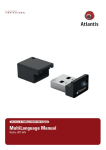
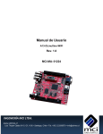
It looks like this:
Then the main menu of the video configuration script shows up:
Choose the resolution and the interface (LCD or VGA). Note that VGA output is hard to implement
and requires both additional hardware and good soldering experience.
The supported resolutions are listed on the next page.
Page 13 of 36
OLIMEX© 2015
A13-SOM user's manual
For LCD:
1. 4.3" (480×272)
2. 7" (800×480)
3. 10" (1024×600)
For VGA (A13-SOM lacks VGA support on hardware level):
0. 1680×1050
1. 1440×900
2. 1360×768
3. 1280×1024
4. 1024×768
5. 800×600
6. 640×480
7. 1920×1080
8. 1280×720
Depending on the display or the screen you want to use with the A13-SOM, you might need to
apply software changes to the prebuilt Android or Linux image. The easiest way would be to do it
on the board itself but it can be done offline too (manipulating the image located on the microSD
card via a microSD card reader).
The tools for script.bin changing are located in /opt/sunxi-tools directory:
#cd /opt/sunxi-tools
#./chscr.sh
This will convert script.bin file from sdcard to script.fex file and the file will be opened using nano
editor. Now you can change the board modules and parameters, save the changes ("CTRL"+"X";
confirm with "Y") and exit ("CTRL"+"X" again) from nano editor.
#./wrscr.sh
this will convert script.fex to script.bin and the script.bin file will be written to the microSD card.
reboot
Reboot the board and the new settings would be enabled.
Alternatively, you can do the changes on the microSD card off the board. You would need to
remove the microSD card and explore it in a microSD card reader. You would need to edit the
configuration file script.bin and edit the settings inside. This file is usually located in the main
partition of a prepared microSD card. Script.bin can't be opened in the binary format so you would
need to convert it to .fex file format first. There are ready-to-use tools that convert script.bin <->
script.fex. Note that script.bin/fex contains configuration settings and definitions not only for the
video output but also for the pin descriptions and names; power setting and much more. If you
really want to modify and customize the default images (to change port functions, port names, to
disable specific peripherals) you would need to be able to edit the script files. Please refer to the
Page 14 of 36
OLIMEX© 2015
A13-SOM user's manual
following web page for more information: http://linux-sunxi.org/Fex_Guide
More information on script editing might be found in the following wiki artice: FEX edit
The typical A13-SOM user would not need to edit the files, however.
2.7 Connecting and calibrating a display
A13-SOM itself has no direct way of connecting an Olimex display (with or without touchscreen
component). Using a display without A13-SOM-WIFI is possible via cables but hard to accomplish
and impractical. It is recommended to try to use a display only if you also have A13-SOM-WIFI at
your disposal.
Unlike other OLIMEX Allwinner boards, the A13-SOM lacks a row of pins that allows the user to
connect a display out-of-the-box. The board's LCD_TR connector is female and has a smaller 0.05''
step. This means that if you use a display made by OLIMEX, you would need additional 2×20
MALE-MALE 0.05'' header to convert the female connector to male. The 0.05'' headers are
somehow hard to find so we sell them here: 0.05'' step connectors. There is also something very
important to notice – since a stand-alone A13-SOM gets powered by 3.3V – this means that you
will not be able to power the display via the board (the Olimex-made displays require 5V of
voltage). You would need to power the display externally.
Newer displays made by Olimex have both 0.1'' and 0.05'' step connectors. So if you are going to
need only the display and a cable (sold separately).
The displays recommended for the board at the moment of writing might be found in the table
below:
Display name
LCD-OlinuXino-4.3TS
LCD-OLinuXino-7
LCD-OLinuXino-7TS
LCD-OLinuXino-10
LCD-OLinuXino-10TS
Size of
display
in inches
4.3
7
7
10
10
Native
resolution
in pixels
480×272
800×480
800×480
1024×600
1024×600
Official
Debian image
support
Yes
Yes
Yes
Yes
Yes
Official
Android image
support
No
Yes
Yes
Yes
Yes
Link to product
page
Product
Product
Product
Product
Product
page
page
page
page
page
The displays whose names contain “TS” - include a resistive touch screen component.
The cable used for connection depends on the specific board you are using and more specifically it
depends on the pitch of the LCD connector of the board. We have two cables – both 40-pins ones
but one for the bigger pitch (0.1'') and the other for the smaller one (0.05''). Each of the displays
listed in the table above has two connectors suitable for both cables:
CABLE-IDC40-6cm – 6cm long cable suitable for 0.1'' step connectors – Product page
CABLE-40-40-10CM – 10cm long cable suitable for 0.05'' step connectors – Product page
Page 15 of 36
OLIMEX© 2015
A13-SOM user's manual
2.7.1 Android calibration
Calibrating a display under Android is pretty straightforward from the Android application.
Important: initially the boards are calibrated for a specific display and resolution. If you re-write the
image (no matter whether the SD card or the NAND memory) you might need to use a mouse to
calibrate the display initially. It might be impossible to calibrate it only by using the touch
component over the display.
2.7.2 Debian calibration
The command that allows calibrating in Debian Linux is:
ts_calibrate
The default Debian video output configuration is set to 7 inch LCD display (800×480). If you want
to change to other video output resolution refer to chapter 2.6 Changing the default image
resolution.
If the problem is under Debian Linux make sure you are properly logged in the LXDE interface!
Else applying calibration would not happen for the current user – if you are calibrating from the X
graphical interface make sure that you are logged as user “olimex” (if calibrating without the X, the
user is “root”).
#su olimex
enter the password: “olimex”, then calibrate the touch screen and reboot the board
#sudo reboot
2.8 Software support
We maintain Linux and Android images for SD card which might be downloaded for free and
modified as the user wishes. The latest images and updates are featured at the wiki article of the
device: https://www.olimex.com/wiki/A13-SOM.
We usually try to provide details on how to build the Linux and the Android images at our
wordpress page: http://olimex.wordpress.com/.
Another useful place is the Olimex forums where a lot of people share their experience and advice:
https://www.olimex.com/forum/.
The official images are a constant work-in-progress – newer releases are packed with better
hardware support, newer kernels and extra features.
You are more than welcome to send or share your suggestions and ideas at our e-mail, the public
forums or irc channel. We would attempt to help in almost every case. We listen to the feedback and
if the majority of users suggest a software change or update we try to implement such. Customer
feedback is very important for the overall state of the software support. However, do not expect full
Page 16 of 36
OLIMEX© 2015
A13-SOM user's manual
Linux or Android software support.
We can share our experience. We can give you full details for things we have tried. We can point
you to a resource or a guide. We can give you general directions to solving a specific problem or
places to look for more information. However, we won’t install a piece of software for you or write
custom program for you. We won't provide a specific software solution to a specific software
problem.
Page 17 of 36
OLIMEX© 2015
A13-SOM user's manual
CHAPTER 3: BOARD DESCRIPTION
3. Introduction to the chapter
Here you get acquainted with the main parts of the board. Note the names used on the board might
differ from the names used below to describe them. For the actual names check the A13-SOM board
itself.
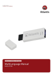
3.1 Layout (top view)
The picture below shows the top side of the board and highlights the most important parts:
Page 18 of 36
OLIMEX© 2015
A13-SOM user's manual
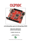
3.2 Layout (bottom view)
Page 19 of 36
OLIMEX© 2015
A13-SOM user's manual
CHAPTER 4: THE ALLWINNER A13 MICROCONTROLLER
4. Introduction to the chapter
In this chapter is located the information about the heart of A13-SOM – its microcontroller. The
information is a modified version of the datasheet provided by its manufacturers.
4.1 The processor
The full list of features might be found below:
CPU/GPU
ARM Cortex-A8 Core
32KB D-Cache/ 32KB I-Cache
256KB L2 Cache
Mali-400 3-D Engine
VPU
HD Video Decoding
1920*1080@30fps
Support H.264, H.263, VC1, Mpeg1/2/4
Divx 3/4/5/6, Xvid, VP6/8, AVS etc
HD Video Encoding
Support encoding in H.264 format
Up to 1920*1080 at 30fps
DPU
LCD Interfaces: CPU, RGB
Memory
DDR2/DDR3: Up to 533MHz
16 bits Data Bus
Memory capacity up to 512MB
MLC/TLC/SLC/EF-NAND
2 flash chips, ECC 64-bit
Support NAND of 5xnm, 4xnm, 3xnm, 2xnm
Support NADN of Samsung, Toshiba, Hynix
Peripherals
USB2.0 OTG, USB2.0 HOST
(OHCI/EHCI)
SD Card V.3.0, eMMC V.4.2
SPI, TWI and UART
integrated Audio Codec
CSI
R-TP Controller
4-wire resistive TP interface
2 points and gesture detection
Boot Devices
NAND Flash
SPI Nor Flash
Page 20 of 36
OLIMEX© 2015
A13-SOM user's manual
SD Card
USB
Powerful Acceleration
Graphic (3D, Mali400 MP)
VPU (1080P)
APU
E-Reader
Ultra-low System Power Consumption
Smart Backlight: auto adjust backlight
acc. to the image display
Package
eLQFP176
More information can be found on Allwinner's web site at the following web-address:
http://www.allwinnertech.com/product/A13.html
4.2 Block diagram
The block diagram is taken from Allwinner's web-site.
Page 21 of 36
OLIMEX© 2015
A13-SOM user's manual
CHAPTER 5: CONTROL CIRCUITY
5. Introduction to the chapter
Here you can find information about reset circuit and quartz crystals locations, the power supply
circuit is also briefly discussed.
5.1 Reset
The board can be reset by the RST button. The reset circuit includes Microchip's MCP130T-300I,
designed to keep a microcontroller in reset until the system voltage has reached the proper level and
stabilized.
The board should be turned off either by the standard OS menu or “poweroff” command or any
other software shutdown procedure. After the choice is confirmed it is safe to disconnect the power
supply unit from the board.
5.2 Clocks
24 MHz quartz crystal Q1 is found at pins 91 (X24MOUT) and 92 (X24MIN) of the A13 processor.
5.3 Power supply circuit
The current consumption for A13-SOM when used separately is around 0.1A when connected to a
3.3V voltage source (provided either at GPIO-1's pin 1 or UART1 3.3V pin).
There are several GND pin and pinhole locations. You can use any of the board's GND for powering
purposes.
The typical consumption of the 512 for the board when combined with A13-SOM-WIFI-4GB might
be found below:
Operating Typical current consumption,
system
in Amperes, at 5V of voltage
Setup
A13-SOM-512 + A13-SOM-WIFI-4GB
Debian
0.45A
A13-SOM-512 + A13-SOM-WIFI-4GB + A13-LCD7-TS
Debian
0.75A
A13-SOM-512 + A13-SOM-WIFI-4GB + A13-LCD7-TS
Android
0.40A
The current consumed usually reaches peaks during start-up when different modules are initialized.
Make sure the supply you provide is capable of powering the board. Note that if there are additional
modules powered by the board, the total power supply requirement would grow. For example,
bigger LCD displays powered via the A13-SOM almost double the current consumption.
For more info on how to power the board refer to chapter “2.3 Powering the board”.
Page 22 of 36
OLIMEX© 2015
A13-SOM user's manual
CHAPTER 6: CONNECTORS AND PINOUT
6. Introduction to the chapter
In this chapter are presented the connectors that can be found on the board all together with their
pinout and notes about them. Jumpers functions are described. Notes and info on specific
peripherals are presented. Notes regarding the interfaces are given.
6.1 Communication with A13-SOM
There is only one way to communicate with A13-SOM without hardware modifications – it is via a
serial cable. If A13-SOM-WIFI is also used, you might also interface the setup via a display or via
SSH.
The direct communication method is via the serial interface. Through male UART1 connector
capable of delivering some information on the COM port of your computer – and then use your
favorite terminal program (puTTy, teraterm, etc) to receive the data/send commands. You can use
USB-SERIAL-CABLE-F with the UART1 interface allowing you to connect to a personal
computer with a free USB port.
Note that the levels at board's UART1 are in CMOS levels (3.3V) and you would need a MAX232
convertor to bring them to TTL ones! This includes the RX and TX line.
It is highly recommended to have an USB-SERIAL-CABLE-F (or similar product) even if you
intend to use the board with a monitor or display. Serial cables usually have built-in MAX232
convertor. In case you set wrong display settings you would be able to recover the settings via the
UART1 connection.
For more information please refer to chapter “2.5 Interacting with the board”.
Page 23 of 36
OLIMEX© 2015
A13-SOM user's manual
6.1.1 UART1 interface
The UART1 interface might be used for serial communication between the board and a personal
computer by default. In case of video output problem a cable might provide needed feedback and
greatly reduce the efforts needed to repair the board or to adjust the software setting.
Note that by default only UART1 is defined as a port suitable for serial debug. You can use our
USB-SERIAL-CABLE-F for debugging.
Even when A13-SOM is mounted on A13-SOM-WIFI the default debug port remains UART1
(despite that it gets additional pins on the big board also for easier access).
Consider table below when connecting the USB-SERIAL-CABLE-F according to the wire color
code. The RX line of the cable (GREEN wire) should go to TX line of the target board; the TX line
of the cable (RED wire) should go to the RX line of
the target board. The BLUE wire should go to the
target's GND line. Make sure to leave free the first
pin (named “3.3”) when connecting the serial cable.
The table of UART1 signals might be found below:
UART1
Pin # Signal name
Processor pin
1 3.3
VCC
2 UART1-TX
A7
3 UART1-RX
B7
4 GND
GND
6.2 MicroSD card connector
The micro SD card slot is primarily used for booting the operating system.
The board works with micro SDHC cards up to 32GB of storage.
As a general precaution be careful with the SD cards you purchase. There is a big percentage of
fake cards due to the low effort required to counterfeit popular brands and the big demand for SD
cards worldwide. When in doubt – try the same operation with another card from another brand.
Olimex sells microSD cards prepared with Linux or Android images, that have been tested – please
refer to chapter “2.2 Requirements”. Currently these are with either 4GB and 8GB of storage
(depending on the purchase date). Of course, if you already have a large enough microSD card you
can download the official Linux image from the wiki pages: https://www.olimex.com/wiki/A13SOM.
When removing the card, please make sure that you release it from the connector by pushing and
NOT by pulling the card directly (this can damage both the connector and the microSD card).
Page 24 of 36
OLIMEX© 2015
A13-SOM user's manual
6.2.1 SD/MMC slot
The schematic related to the SD/MMC (microSD connector) is shown below:
SD/MMC slot is a microSD card slot connector, located on the top of the board.
This slot is typically used for booting the OS, due to the larger capacities of the microSD cards
(compared to SD or MMC cards). It is suggested to have an SD card with a proper Linux/Android
image especially if you have ordered a version of the board without NAND memory. It is also
recommended to use Class 10 (10MByte/sec) card for faster read/write operations, lower class cards
(especially higher capacity ones) might slow down the whole system.
The table with the microSD card signals might be found below:
Pin # Connector signal name
1 DAT2/RES
2 CD/DAT3/CS
3 CMD/DI
4 VDD
5 CLK/SCLK
6 VSS
7 DAT0/DO
8 DAT1/RES
9 CARD DETECT(SYMBOL)
13 GND
SD/MMC1 connector
Wire name (processor pin number)
SDC0_DATA2 (113)
SDC0_DATA3 (112)
SDC0_CMD (111)
SD_VCC
SDC0_SCLK (110)
GND
SDC0_DATA0 (108)
SDC0_DATA1 (107)
SD0CARD-DETECT (155)
GND
6.3 Power pins for external power supply
There are two power pins suitable for powering the board. These are located on different places of
A13-SOM – one at the UART1 connector, the other on GPIO1 connector. To power the board you
need to provide 3.3V to one of them. You can use any of the pins or the pinholes named GND.
The required current may vary depending on the peripherals connected to the board. The power
supply should be capable of providing at least 0.5A of current.
Page 25 of 36
OLIMEX© 2015
A13-SOM user's manual
The recommended way of powering the board is via A13-SOM-WIFI.
More information about the powering can be found in chapter “5.3 Power supply circuit” of this
manual.
6.4 GPIO connectors
There are 3 female GPIO connectors all located on the top side of A13-SOM. They ease the access
to processors pins. These connectors also provide a way to mount the board to a board with
peripherals like A13-SOM-WIFI. The first of the GPIO connectors is a 40-pin one and the other two
are 10-pin ones.
Below you would find a general overview of the board's GPIO and LCD pins. They might be also
found in the tables further down in the chapter. To understand better what each processor pin does it
might be a good idea to refer to the datasheet of the A13 processor. The schematic of the board of
peripherals A13-SOM-WIFI might also help you identify the main function of the pins.
To keep the form factor as small as possible the GPIO connectors have 0.05'' step.
IMPORTANT: the connectors are very fragile – if you attempt to disconnect the board by pulling
only one side out it might break! Furthermore – you might bend the board's pins! Use pliers or other
suitable object to disconnect the connectors carefully!
Page 26 of 36
OLIMEX© 2015
A13-SOM user's manual
OLIMEX sells additional and replacement male and female 0.05'' (50 mil) step connectors. We also
have a female-female cable named CABLE-40-40-10CM, suitable for the 40-pin connectors.
The only power line at the GPIO connectors that might be used as input is the '3.3V' one at GPIO1.
The rest of the power signals are outputs and it would be incorrect to try to power the board from
there.
6.4.1 GPIO-1 (General Purpose Input/Output) 40pin connector
GPIO-1 connector
Pin # Signal name
Processor pin
Pin # Signal name Processor pin
1
3.3V
-POWER CIRCUIT-
2
GND
-POWER CIRCUIT-
3
RESET_N
RESET_N (159)
4
NMI_N
NMI_N (158)
5
PIN4/TWI0-SCK
PB0/TWI0-SCK (101)
6
PIN39
PG11/SPI1_MOSI/UART3_CTS/EINT11 (14)
7
PIN5/TWI0-SDA
PB1/TWI1-SDA (102)
8
PIN38
PG10/SPI1_CLK/UART3_RX/EINT10 (13)
9
PIN6/PWM0
PB2/PWM/SPI2_MOSI/EINT16 (103)
10
PIN37/LED1
PG9/SPI1_CS0/UART3_TX/EINT9 (12)
11
PIN7
PB3/IR_TX/SPI2_MISO/EINT17 (150)
12
PIN36
PE11/CSI_D7/UART1_RX (125)
13
PIN8
PB4/IR_RX/EINT18 (104)
14
PIN35
PE10/CSI_D6/UART1_TX (124)
15
PIN9
PB10/SPI2_CS1/EINT24 (10)
16
PIN34
PE9/CSI_D5/SDC2_CLK (123)
17
PIN10/TWI1-SCK PB15/TWI1_SCK (105)
18
PIN33
PE8/CSI_D4/SDC2_CMD (122)
19
PIN11/TWI1-SDA PB16/TWI1_SDA (106)
20
PIN32
PE7/CSI_D3/SDC2_D3 (121)
21
PIN12/NWE
PC0/NWE/SPI_MOSI (8)
22
PIN31
PE6/CSI_D2/SDC2_D2 (120)
23
PIN13/NALE
PC1/NALE/SPI_MISO (7)
24
PIN30
PE5/CSI_D1/SDC2_D1 (119)
25
PIN15/NCLE
PC2/NCLE/SPI_CLK (6)
26
PIN29
PE4/CSI_D0/SDC2_D0 (118)
27
PIN15/NCE1
PC3/NCE1/SPI_CS0 (3)
28
PIN28/NDQS
PC19/NDQS (162)
29
PIN16/NCE0
PC4/NCE0 (2)
30
PIN27/NDQ7
PC15/NDQ7/SDC2_D7 (165)
31
PIN17/NRE
PC5/NRE (1)
32
PIN26/NDQ6
PC14/NDQ6/SDC2_D6 (166)
33
PIN18/NRB0
PC6/NRB0/SDC2_SMD (176)
34
PIN25/NDQ5
PC13/NDQ5/SDC2_D5 (167)
35
PIN19/NRB1
PC7/NRB1/SDC2_CLK (175)
36
PIN24/NDQ4
PC12/NDQ4/SDC2_D4 (168)
37
PIN20/NDQ0
PC8/NDQ0/SDC2_D0 (174)
38
PIN23/NDQ3
PC11/NDQ3/SDC2_D3 (170)
39
PIN21/NDQ1
PC9/NDQ1/SDC2_D1 (172)
40
PIN22/NDQ2
PC10/NDQ2/SDC2_D2 (171)
Note that signals PIN6/PWM0, PIN7, PIN8, PIN9 (respectively pins 9, 11, 13, 15) are also available
at the LCD_TR connector. Avoid multiplexing.
6.4.2 GPIO-2 (General Purpose Input/Output) 10pin connector
GPIO-2 connector
GPIO pin# Signal name
Processor pin#
GPIO pin# Signal name
Processor pin#
1
UDP0
UDP0 (94)
2
VMIC
VMIC (85)
3
UDM0
UDM0 (93)
4
MICIN1
MICIN1 (84)
5
UDP1
UDP1 (96)
6
HPOUT2
HPOUTL (74)
7
UDM1
UDM1 (95)
8
HPCOM
HPCOM (77)
9
LRADC
LRADC (86)
10
HPOUTR
HPOUTR (78)
Page 27 of 36
OLIMEX© 2015
A13-SOM user's manual
6.4.3 GPIO-3 (General Purpose Input/Output) 10pin connector
GPIO-3 connector
Pin # Signal name
Processor pin#
Pin #
Signal name
Processor pin#
1
SPI2_CS0
PE0/CSI_PCLK/SPI2_CS0/EIN14 (114)
2
USB0-VBUSDET
PG1/EINT1 (154)
3
SPI2_CLK
PE1/CSI_MCLK/SPI2_CLK/EIN15 (115)
4
USB0-IDDET
PG2/EINT2 (153)
5
SPI2_MOSI
PE2/CSI_VSYNC/SPI2_MOSI (116)
6
USB0-DRV
PG12/SPI1_MISO/UART3_RTS (15)
7
SPI2_MISO
PE3/CSI_HSYNC/SPI2_MISO (117)
8
TWI2-SCK
PB17/TWI2_SCK (161)
9
UBOOT
UBOOT (157)
10
TWI2-SDA
PB18/TWI2_SDA (160)
6.5 LCD_TR 40pin connector
The pins used for LCD display connection are led out to a separate 40pin connecter for ease. We
have tested the ability of the board to interact with such a display. These pins also allow the user to
attach additional hardware, check readings or perform hardware debug.
Important: it is a good idea to use A13-SOM-WIFI that provides a 0.1 step connector. Alternatively
the connector can be used standalone but you would need to either use wires or male-male
connector and two different 40PIN ribbon cables to connect an Olimex display and the LCD_CON.
Please note that the smallest display (4.3'', 480×272) is not suitable for the official Android images
we provide, however it can be used with Debian Linux.
The biggest display (15.6'', 1366×768 or 1920×1080) is not supported by the A13-SOM design. The
core processor lacks the required computing power for a smooth operation.
LCD_CON connector
Pin# Signal name
Processor pin
Pin#
Signal name
Processor pin
1
+5V
-POWER CIRCUIT-
2
GND
-POWER CIRCUIT-
3
3.3V
-POWER CIRCUIT-
4
GND
-POWER CIRCUIT-
5
LCD_D18
PD18/LCD_D18 (135)
6
NOT CONNECTED
NOT CONNECTED
7
LCD_D18
PD18/LCD_D18 (135)
8
LCD_D19
PD19/LCD_D19 (134)
9
LCD_D20
PD18/LCD_D20 (133)
10
LCD_D21
PD21/LCD_D21 (132)
11
LCD_D22
PD18/LCD_D21 (132)
12
LCD_D23
PD23/LCD_D23 (130)
13
LCD_D10
PD10/LCD_D10 (141)
14
NOT CONNECTED
NOT CONNECTED
15
LCD_D10
PD10/LCD_D10 (141)
16
LCD_D11
PD11/LCD_D11 (140)
17
LCD_D12
PD12/LCD_D12 (139)
18
LCD_D13
PD13/LCD_D13 (138)
19
LCD_D14
PD14/LCD_D14 (137)
20
LCD_D15
PD15/LCD_D15 (136)
21
LCD_D2
PD2/LCD_D2 (148)
22
NOT CONNECTED
NOT CONNECTED
23
LCD_D2
PD2/LCD_D2 (148)
24
LCD_D3
PD3/LCD_D3 (147)
25
LCD_D4
PD4/LCD_D4 (146)
26
LCD_D5
PD5/LCD_D5 (145)
27
LCD_D6
PD6/LCD_D6 (144)
28
LCD_D7
PD7/LCD_D7 (43)
29
LCD_HSYNC
PD26/LCD_HSYNC (127)
30
LCD_VSYNC
PD27/LCD_VSYNC (126)
31
LCD_CLK
PD24/LCD_CLK (129)
32
LCD_DE
PD25/LCD_DE (128)
33
PIN7
PB3/IR_TX/SPI2_MISO/EINT17 (150)
34
PIN8
PB4/IR_RX/EINT18 (104)
35
PIN9
PB10/SPI2_CS1/EINT24 (10)
36
PIN6/PWM0
PB2/PWM/SPI2_MOSI/EINT16 (103)
37
TPX1
TPX1 (89)
38
TPX2
TPX2 (87)
39
TPY1
TPY1 (90)
40
TPY2
TYP2 (88)
Page 28 of 36
OLIMEX© 2015
A13-SOM user's manual
Note that signals PIN6/PWM0, PIN7, PIN8, PIN9 (respectively pins 36, 33, 34, 35) are also
available at the LCD_TR connector. Avoid multiplexing.
6.6 Jumper description
The board has a couple of hardware SMT jumpers which are used during the testing of the board.
It is not recommended to change the position of any jumpers located on A13-SOM.
Board jumpers
Jumper name
Type
Default position
Function
1.5V_E
SMT
CLOSED
If open disables 1.5V to the A13
1.2V_E
SMT
CLOSED
If open disables 1.2V to the A13
6.7 Additional hardware components
The components below are mounted on the A13-SOM but are not discussed above. They are listed
here for completeness:
Reset button – used to reset the board
Power button – used to reset the board
A13-SOM-256 has 256MB RAM = 1×[2Gb(128M x 16)] DDR3 SDRAM – the exact memory
used in the board revision mentioned is Hynix 5TQ2G63BFR
A13-SOM-512 has 512MB RAM = 1×[4Gb(256M x 16b)] DDR3 SDRAM – the exact memory
used currently in the board is SAMSUNG K4B4G1646D-BCK0
The DDR3 memory part name in the schematic might be outdated. We have used a number of
different but fully compatible DDR3 memories due to supply unavailability. It is always
recommended to check the exact memory name printed on the component itself.
LED1 – green – user-programmable LED, turns after a successful boot.
Page 29 of 36
OLIMEX© 2015
A13-SOM user's manual
CHAPTER 7: SCHEMATICS
7. Introduction to the chapter
In this chapter is located information about the schematics describing logically and physically A13SOM.
7.1 Eagle schematic
OLinuXino schematics may be found it on the OLinuXino's GitHub repository:
https://github.com/OLIMEX/SOM/tree/master/A13. You can download the whole repository as .zip
without having a GitHub account.
We mostly use Eagle by Cad Soft 4.16r2 for designing. However, the files should be compatible
with the latest Eagle available. Cad Soft offers a trial version of their software that allows you to
inspect schematics and board files (without being able to modify them).
This work is licensed under the Creative Commons Attribution-ShareAlike 3.0 Unported License.
To view a copy of this license, visit http://creativecommons.org/licenses/by-sa/3.0/.
If you are looking for a schematic of an older revision of the board and it isn't available at our web
site you may request it by the support e-mail.
Page 30 of 36
OLIMEX© 2015
A13-SOM user's manual
7.2 Physical dimensions
Note that all dimensions are in mils.
Page 31 of 36
OLIMEX© 2015
A13-SOM user's manual
CHAPTER 8: REVISION HISTORY AND SUPPORT
8. Introduction to the chapter
In this chapter you will find the current and the previous version of the document you are reading.
Also the web-page for your device is listed. Be sure to check it after a purchase for the latest
available updates and examples.
8.1 Document revision
Document revision Changes
Modified page
A, 26.11.14
Initial manual release
All
Updated RAM memory to reflect latest
schematic
Updated board revision
29
B, 17.03.15
32
8.2 Board revision
Remember to check the schematics and the board design files to compare the differences.
Board revision
Notable changes
D
Initial release of the board
E
1. All component libraries were updated.
2. R25, R26, R27, R28, R29 and R30 – pull-ups (NA) to I2Cs were
added.
3. Lowered the heat generated under heavy loads – the GND polygons
under the MCU were enlarged as much as possible (especially in
Route2).
Page 32 of 36
OLIMEX© 2015
A13-SOM user's manual
8.3 Useful web links and purchase codes
A13-SOM web pages are here:
https://www.olimex.com/Products/SOM/A13/A13-SOM-256/
https://www.olimex.com/Products/SOM/A13/A13-SOM-512/
Wiki article of the board: https://www.olimex.com/wiki/A13-SOM
A place for general questions, FAQ or friendly talk: https://www.olimex.com/forum/.
You can get the latest updates on the software at the GitHub:
https://github.com/OLIMEX/SOM/tree/master/A13.
You may may join our IRC channel #olimex @ freenode.net (http://webchat.freenode.net/?
channels=olimex).
The sunxi community is the main force behind the Allwinner Linux support: http://linuxsunxi.org/Main_Page.
ORDER CODES:
A13-SOM-256 – the 256MB DDR3 RAM version of the product
A13-SOM-512 – the 512MB DDR3 RAM version of the product
A13-SOM-WIFI – expansion board that can be directly mounted over A13-SOM – it adds USBmini port, a WIFI module with built-in antenna, LCD display connector with 0.1'' step and routes a
number of frequently used signals to the easier to access 0.1'' row of pinholes. The sources
schematics of A13-SOM-WIFI are available for download and the board is considered open
hardware.
USB-SERIAL-CABLE-F – female USB serial console cable – provides the easiest way of
debugging
A13-SOM-256-DEBIAN-SD – a tested, class 10 micro SD card with the latest (by the time of
leaving the Olimex facilities) official Debian release, suitable for the 256MB version of the board
A13-SOM-512-DEBIAN-SD – same as above suitable for the 512MB version of the board
A13-SOM-512-ANDROID-SD – a tested, class 10 micro SD card with the latest (by the time of
leaving Olimex facilities) official Android Linux release
USB-MINI-CABLE – standard USB type A to USB type mini cable
How to purchase?
You can purchase directly from our online shop or from any of our distributors. Note that usually it
might be faster and cheaper to purchase Olimex products from our distributors. List of confirmed
Olimex LTD distributors and resellers: https://www.olimex.com/Distributors.
Please visit https://www.olimex.com/ for more info.
Page 33 of 36
OLIMEX© 2015
A13-SOM user's manual
8.4 Frequently asked questions
Q: I powered my board, it showed a logo and then nothing happened. What might be the
problem?
A: This might be due to a number of reasons but it is recommended to try the following:
1. Download latest official image from our wiki (preferably Debian for SD card), and upload it to
an SD card again. There are instructions how to do it in the other questions below. Try if the board
works now.
2. Check if your power supply provides enough current, try with different/better power supply.
3. If using A13-SOM-WIFI, please check the USB hub you are using, plug the USB cable directly
to the back of your personal computer, check the USB cable.
4. The board might enter sleep mode very fast (especially if the Android was turned off without the
“Quick Boot” mode being ticked on). Try pressing or holding down the PWR button for a couple of
seconds to wake it up.
Q: How do I write the Linux image to a micro SD card to use with my A13 board?
A: First visit the wiki article for the board and download the archive with the image. Then write the
Linux image to a microSD card.
Under Windows we use Win32 Disk Imager: http://sourceforge.net/projects/win32diskimager/
Download Win32 Disk Imager software
Insert card
Start program
Select file
Click "write"
To write a Linux image to an SD card under Linux:
For instance you have an image with the file name of "debian_2g.img". It would be downloaded to
the SD card connected to a Linux machine using one of the following commands:
# dd bs=4M oflag=sync if=debian_2g.img of=/dev/sdX
or
# cp debian_2g.img /dev/sdX
where X is the uSD card.
Page 34 of 36
OLIMEX© 2015
A13-SOM user's manual
Q: How to generate boot-able SD-card Debian Linux image for A13-SOM-256?
The building instructions might be found at the following link: google drive
Official Wordpress post on Debian image release: Wordpress post
Q: How to detect and enable the Ethernet controller (if it is disabled by default)?
A: You can enable it by following these two steps:
1. To check under what name the LAN is associated write "ifconfig –a"
2. If, for example, it is under eth0 name, then write: "dhclient eth0"
This should enable the Ethernet and then SSH would also be available.
You can also enable auto detection of Ethernet on power-up by removing the comment #auto eth0 in
/etc/network/interfaces in the Linux image.
How to download Android image to the NAND memory of my A13-SOM board?
The only A13-SOM setup suitable of booting Android from the NAND memory is A13-SOM-512
with A13-SOM-WIFI shield.
To repair the image on the NAND re-upload it following these steps:
1. Install and run LiveSuit (can be found here: google drive). Another location for LiveSuit at the
Linux sunxi wiki: http://linux-sunxi.org/LiveSuit
2. Download and extract the latest official image from the Android section of the wiki: A13-SOM256 article. Make sure that the download link you visit clearly indicates that the image is suitable
for the NAND memory since there are images suitable for microSD card also. The images suitable
for the microSD memory and those suitable for microSD card are different. However, the upload
method is almost identical – using LiveSuit.
3. Go to firmware tab of the program and point to the already downloaded and extracted Android
image.
4. Disconnect the power supply and USB cable from the A13 board.
5. Press and hold UBOOT/HOME button, apply power supply (the requirement varies), release
UBOOT/HOME button.
6. Connect USB cable to the mini USB connector of A13-SOM-WIFI
7. You will be asked for drivers for the bootloader. Navigate to the folder where you extracted the
LiveSuit and install the drivers from the respective executable (or manually point the installer to the
drivers folder in the LiveSuit installation path).
8. LiveSuit will detect the board and would ask whether you wish to also of writing the image.
Choose method of writing the image and confirm your wish to write the image.
9. Wait till upgrade succeeds.
Note that it is not recommended to have your mini USB connected to an external USB hub. This
might cause delays and might distort the signal levels. Always test with the USB connected straight
to the USB ports of your computer.
Page 35 of 36
OLIMEX© 2015
A13-SOM user's manual
8.5 Product support
For product support, hardware information and error reports mail to: [email protected]. All
document or hardware feedback is welcome. Note that we are primarily a hardware company and
our software support is limited. Please consider reading the paragraph below about the warranty of
Olimex products.
All goods are checked before they are sent out. In the unlikely event that goods are faulty,
they must be returned, to OLIMEX at the address listed on your order invoice.
OLIMEX will not accept goods that have clearly been used more than the amount needed to
evaluate their functionality.
If the goods are found to be in working condition, and the lack of functionality is a result of
lack of knowledge on the customers part, no refund will be made, but the goods will be returned
to the user at their expense.
All returns must be authorized by an RMA Number. Email [email protected] for authorization
number before shipping back any merchandise. Please include your name, phone number and order
number in your email request.
Returns for any unaffected development board, programmer, tools, and cables permitted within 7
days from the date of receipt of merchandise. After such time, all sales are considered final.
Returns of incorrect ordered items are allowed subject to a 10% restocking fee. What is
unaffected? If you hooked it to power, you affected it. To be clear, this includes items that
have been soldered to, or have had their firmware changed. Because of the nature of the
products we deal with (prototyping electronic tools) we cannot allow returns of items that have
been programmed, powered up, or otherwise changed post shipment from our warehouse.
All returned merchandise must be in its original mint and clean condition. Returns on damaged,
scratched, programmed, burnt, or otherwise 'played with' merchandise will not be accepted.
All returns must include all the factory accessories which come with the item. This includes
any In-Circuit-Serial-Programming cables, anti-static packing, boxes, etc.
With your return, enclose your PO#. Also include a brief letter of explanation of why the
merchandise is being returned and state your request for either a refund or an exchange.
Include the authorization number on this letter, and on the outside of the shipping box.
Please note: It is your responsibility to ensure that returned goods reach us. Please use a
reliable form of shipping. If we do not receive your package we will not be held liable.
Shipping and handling charges are not refundable. We are not responsible for any shipping
charges of merchandise being returned to us or returning working items to you.
The full text might be found at https://www.olimex.com/wiki/GTC#Warranty for future reference.
Page 36 of 36