1
A13-OLinuXino and A13-OLinuXino-WIFI
Open-source single-board
Android 4.0 mini-computer
USER’S MANUAL
Revision F, February 2015
Designed by OLIMEX Ltd, 2012
All boards produced by Olimex LTD are ROHS compliant
OLIMEX© 2014
A13-OLinuXino user's manual
DISCLAIMER
© 2015 Olimex Ltd. Olimex®, logo and combinations thereof, are registered trademarks of Olimex Ltd.
Other product names may be trademarks of others and the rights belong to their respective owners.
The information in this document is provided in connection with Olimex products. No license, express
or implied or otherwise, to any intellectual property right is granted by this document or in connection
with the sale of Olimex products.
The Hardware project is released under the Creative Commons Attribution-Share Alike 3.0 United States
License. You may reproduce it for both your own personal use, and for commercial use. You will have to
provide a link to the original creator of the project http://www.olimex.com on any documentation or website.
You may also modify the files, but you must then release them as well under the same terms. Credit can be
attributed through a link to the creator website: http://www.olimex.com
The software is released under GPL.
It is possible that the pictures in this manual differ from the latest revision of the board.
The product described in this document is subject to continuous development and improvements. All
particulars of the product and its use contained in this document are given by OLIMEX in good faith.
However all warranties implied or expressed including but not limited to implied warranties of
merchantability or fitness for purpose are excluded. This document is intended only to assist the reader in the
use of the product. OLIMEX Ltd. shall not be liable for any loss or damage arising from the use of any
information in this document or any error or omission in such information or any incorrect use of the
product.
This evaluation board/kit is intended for use for engineering development, demonstration, or evaluation
purposes only and is not considered by OLIMEX to be a finished end-product fit for general consumer use.
Persons handling the product must have electronics training and observe good engineering practice
standards. As such, the goods being provided are not intended to be complete in terms of required design-,
marketing-, and/or manufacturing-related protective considerations, including product safety and
environmental measures typically found in end products that incorporate such semiconductor components or
circuit boards.
Olimex currently deals with a variety of customers for products, and therefore our arrangement with the user
is not exclusive. Olimex assumes no liability for applications assistance, customer product design, software
performance, or infringement of patents or services described herein.
THERE IS NO WARRANTY FOR THE DESIGN MATERIALS AND THE
COMPONENTS USED TO CREATE A13-OLINUXINO AND A13-OLINUXINOWIFI. THEY ARE CONSIDERED SUITABLE ONLY FOR A13-OLINUXINO AND
A13-OLINUXINO-WIFI.
Page 2 of 37
OLIMEX© 2014
A13-OLinuXino user's manual
Table of Contents
DISCLAIMER............................................................................................................. 2
CHAPTER 1: OVERVIEW........................................................................................5
1. Introduction to the chapter.......................................................................................................5
1.1 Features.....................................................................................................................................5
1.2 Target market and purpose of the board...............................................................................6
1.3 Board variants..........................................................................................................................6
1.4 Organization.............................................................................................................................6
CHAPTER 2: SETTING UP THE OLINUXINO BOARD.....................................8
2. Introduction to the chapter.......................................................................................................8
2.1 Electrostatic warning...............................................................................................................8
2.2 Requirements........................................................................................................................... 8
2.3 Powering the board..................................................................................................................9
2.4 Prebuilt software....................................................................................................................10
2.5 Button functions in Android..................................................................................................11
2.6 How we configured the Android image................................................................................11
2.6.1. Getting the Android SDK tools...................................................................................................................11
2.6.2. Adding information for the board in the Linux........................................................................................11
2.6.3. Installing the SDK tools..............................................................................................................................12
2.6.4. Connecting the A13-OLinuXino................................................................................................................12
2.6.5. Downloading the default config file and script tool..................................................................................13
2.6.6. Applying the script and uploading the confing.........................................................................................13
2.6.7. Restarting the A13-OLinuXino..................................................................................................................13
2.7 GPIO under Debian...............................................................................................................13
2.8 I2C and SPI under Debian....................................................................................................15
2.9 Software support....................................................................................................................15
CHAPTER 3: A13-OLINUXINO BOARD DESCRIPTION.................................16
3. Introduction to the chapter.....................................................................................................16
3.1 Layout (top view)...................................................................................................................16
CHAPTER 4: THE ALLWINNER A13 MICROCONTROLLER.......................17
4. Introduction to the chapter.....................................................................................................17
4.1 The microcontroller...............................................................................................................17
4.2 Block diagram........................................................................................................................ 19
CHAPTER 5: CONTROL CIRCUITY................................................................... 20
5. Introduction to the chapter.....................................................................................................20
5.1 Reset........................................................................................................................................20
5.2 Clocks......................................................................................................................................20
5.3 Power supply circuit.............................................................................................................. 20
CHAPTER 6: CONNECTORS AND PINOUT......................................................21
6. Introduction to the chapter.....................................................................................................21
Page 3 of 37
OLIMEX© 2014
A13-OLinuXino user's manual
6.1 Communication with the A13............................................................................................... 21
6.1.1 USB communication.....................................................................................................................................21
6.1.2 UART1 interface...........................................................................................................................................22
6.2 SD/MMC slot..........................................................................................................................23
6.3 UEXT module.........................................................................................................................24
6.4 GPIO-1 (General Purpose Input/Output) 10pin connector...............................................25
6.5 GPIO-2 (General Purpose Input/Output) 40pin connector...............................................26
6.6 LCD_CON 40pin connector..................................................................................................27
6.7 PWR Jack...............................................................................................................................28
6.8 Headphones and microphone connector..............................................................................28
6.9 Battery connector...................................................................................................................29
6.7 VGA video connector.............................................................................................................29
6.8 Jumper description................................................................................................................30
6.8.1 CE_NAND_E................................................................................................................................................30
6.8.2 3.3V_OPTION, 1.5V_E................................................................................................................................30
6.8.3 5V_E.............................................................................................................................................................. 30
6.8.4 HOST_EN, 5V_E_WIFI, WIFI-3.3V/5V_USB..........................................................................................30
6.9 Additional hardware components........................................................................................ 30
CHAPTER 7: SCHEMATICS..................................................................................32
7. Introduction to the chapter.....................................................................................................32
7.1 Eagle schematic......................................................................................................................32
7.2 Physical dimensions...............................................................................................................33
CHAPTER 8: REVISION HISTORY AND SUPPORT........................................ 34
8. Introduction to the chapter.....................................................................................................34
8.1 Document revision................................................................................................................. 34
8.2 Board revision........................................................................................................................ 35
8.3 Useful web links and purchase codes...................................................................................36
8.4 Product support..................................................................................................................... 37
Page 4 of 37
OLIMEX© 2015
A13-OLinuXino user's manual
CHAPTER 1: OVERVIEW
1. Introduction to the chapter
Thank you for choosing the OLinuXino single board computer from Olimex! This document
provides a user’s guide for the Olimex OLinuXino board. As an overview, this chapter gives the
scope of this document and lists the board’s features. The document’s organization is then detailed.
The OLinuXino development board enables code development of applications running on the
microcontroller A13, manufactured by Allwinner Technology from China.
OLinuXino is an open-source, open-hardware project and all documentation is available to the
customer.
1.1 Features
The board has the following set of features:
•
•
•
•
•
•
•
•
•
•
•
•
•
•
•
•
A13 Cortex A8 processor at 1GHz, 3D Mali400 GPU
512 MB RAM
6-16VDC input power supply, noise immune design
3 + 1 USB Host, 3 available for users 1 for (optional) WIFI RTL8188CU 802.11n 150Mbit
module on board
1 USB OTG which can power the board
SD-card connector for booting the Linux image
(optional) 4GB NAND flash
VGA video output – 800×600 resolution
LCD signals available on connector so you still can use LCD if you diasble VGA/HDMI
Audio Output
Microphone input
RTC PCF8536 on board for real time clock and alarms
5 Keys on board for android navigation
UEXT connector for connecting addtional UEXT modules like Zigbee, Bluetooth, Relays,
etc
GPIO connector with 68/74 pins and these signals : 17 for adding NAND flash; 22 for
connecting LCDs; 20+4 including 8 GPIOs which can be input, output, interrupt sources; 3x
I2C; 2x UARTs; SDIO2 for connectinf SDcards and modules; 5 system pins: +5V, +3.3V,
GND, RESET, NMI
(Optional low cost 7" LCD with touchscreen)
Page 5 of 37
OLIMEX© 2015
A13-OLinuXino user's manual
1.2 Target market and purpose of the board
The boards from the OLinuXino family are easy to setup and powerful. They are suitable for
embedded programming enthusiasts, Linux and Android gadget fans and also professionals (since
its low cost makes it very good solution for application orientated embedded systems). The main
usage of the board is software embedded development without the urge of understanding perfectly
the hardware.
The strong points of the boards are the processor speed, the mobility of the board and the low ratio
price to productivity.
Customers have full access to the technical documentation of the board. The software is released
under General Purpose License and the board is considered open-hardware.
1.3 Board variants
There are three major processor variants. According to the names: A13-OLinuXino and A13OLinuXino-MICRO and A13-SOM.
The base model has also two flavors: A13-OLinuXino and A13-OLinuXino-WIFI. The first one is
the base model that goes without any operating system image on board, while the second has two
additional components – a WIFI module on the board and NAND memory with stored Android
image.
The A13-OLinuXino-Micro differs from the base A13-OLinuXino by having only 1 USB host, 1
USB OTG, no power connector, no NAND memory, no WIFI, no audio out connector, less buttons.
If you are looking for an A13 board with tiny dimensions and suitable for implementing in own
designs then refer to A13-SOM board – it has tiny dimensions.
There are more powerful A10 and A20 designs that Olimex manufactures nowadays. Boards like
A20-OLinuXino-LIME; A20-OLinuXino-MICRO and A20-OLinuXino-LIME2 are generally faster
and capable of much better video output.
Page 6 of 37
OLIMEX© 2015
A13-OLinuXino user's manual
1.4 Document organization
Each section in this document covers a separate topic, organized as follow:
– Chapter 1 is an overview of the board usage and features
– Chapter 2 provides a guide for quickly setting up the board and software notes
– Chapter 3 contains the general board diagram and layout
– Chapter 4 describes the component that is the heart of the board: the A13 – Allwinner
processor
– Chapter 5 is an explanation of the control circuitry associated with the microcontroller to
reset. Also shows the clocks on the board
– Chapter 6 covers the connector pinout, peripherals and jumper description
– Chapter 7 provides the schematics
– Chapter 8 contains the revision history, useful links and support information
Page 7 of 37
OLIMEX© 2015
A13-OLinuXino user's manual
CHAPTER 2: SETTING UP THE OLINUXINO BOARD
2. Introduction to the chapter
This section helps you set up the OLinuXino development board for the first time. Please consider
first the electrostatic warning to avoid damaging the board, then discover the hardware and software
required to operate the board.
The procedure to power up the board is given, and a description of the default board behavior is
detailed.
2.1 Electrostatic warning
OLinuXino is shipped in a protective anti-static package. The board must not be exposed to high
electrostatic potentials. A grounding strap or similar protective device should be worn when
handling the board. Avoid touching the component pins or any other metallic element.
2.2 Requirements
In order to set up the OLinuXino optimally, the following items are required:
- 6V to 16V, 6W required (6V @ 1A or 16V @ 0.4A) – for optimal power
- LCD (preferably with touchscreen panel) display for the LCD_CON OR TV monitor with RGB
port
- A USB mouse – if you use touchscreen LCD you might skip the mouse
Additional items include:
- USB keyboard – for convenience with text input
- USB-SERIAL-CABLE-F – for serial communication with UART1 connector
- USB-MINI-CABLE – for connecting with the USB OTG and being able to firmware update ot
power A13-OLinuXino
- Wireless internet connectivity or USB modem – for browser access and access to the Android
market
Some of the suggested items can be purchased by Olimex, for instance:
SY0612E – power supply adapter 12V/0.5A for A13-OLinuXino
USB-SERIAL-CABLE-F – USB serial console cable female
USB-MINI-CABLE – standard USB type A to USB type mini cable
Page 8 of 37
OLIMEX© 2015
A13-OLinuXino user's manual
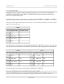
The recommended LCD display for the board is 7 inch with an optional touch screen panels suitable
for the board:
Display name
LCD-OLinuXino-7
Size of
display
in inches
7
Native
resolution
in pixels
800×480
Official
Debian image
support
Yes
Official
Link to product
Android image page
support
Yes
Product page
LCD-OLinuXino-7TS
7
800×480
Yes
Yes
Product page
Note that if you wish to use one of the LCD displays mentioned above you need to upload different
Android image – configured for 480×800 screen resolution.
2.3 Powering the board
There are three possible ways of powering A13-OLinuXino – via external supply using the power
jack, via a battery using the battery connector or via the USB OTG connector. Depending on your
preferred way of powering A13-OLinuXino you might need additional hardware.
The preferred way of powering board is via the PWR jack with 6Vdc to 16Vdc with a power of 6W
(e.g. 6Vx1A to 16Vx0.4A). This will make the board fully powered and able to power all the
peripherals connected to it.
When powered by the typical 3.7V Lithium-polymer battery the board will be fully functional and
you will be able to operate with most of the peripherals. However when using all three USB-A
connectors and an LCD connected to the LCD_con it might cause flickering and not sufficient
power. If you suspect the power is not enough for the peripherals you have connected use the PWR
jack.
The board can be also powered by the USB OTG connector (mini USB standard) but the voltage
provided is not enough to power a possible LCD connected to the LCD_con. However, this power
option is capable of driving the board when using external display connected to the VGA connector.
If you have a standard LCD display connected to LCD_con, Android and WIFI running the typical
consumption is between 150mA and 350mA depending on the current load. While the board is in
stand-by mode it consumes a minimum of 60mA. All the three approximate values above were
taken when I applied 12V to the board.
Important! Avoid disconnecting the power supply while Android or Linux is running, since that
might corrupt the operating system and you will need to install the OS again (for Android install
instructions check chapter 2.6. Use the PWR_BUT before disconnecting the supply.
If the board has entered power-down state you can bring it back without restart using the
PWR_BUT.
Page 9 of 37
OLIMEX© 2015
A13-OLinuXino user's manual
For the European customers we sell a power supply adapter 12V/0.5A – SY0612E. We also sell
USB OTG to USB type A cables if you lack such.
2.4 Prebuilt software
The A13-OLinuXino-WIFI board comes with Android 4.0 ready to use. The default settings of the
software are followed.
Note that the A13-OLinuXino (standard version without WIFI) lacks NAND memory and there isn't
OS uploaded on the shipped boards (no Android).
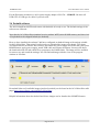
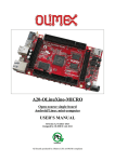
How we have installed the software? We have configured an Android image with settings suitable
for A13-OLinuXino. Then using LiveSuit tools we uploaded the image to the board. To activate
A13 bootloader do as follows: run Livesuit, disconnect the power supply and USB cable, then press
HOME button, apply power supply, attach USB cable and release the button, Livesuit will detect
the bootloader and will ask which file to program to the NAND flash. The image will be available
for users to try and tweak the settings. You can find and image with the view of the progress
window in LiveSuit:
Download links to all available images (and tools needed) can be found at the A13-OLinuXino wiki
page: https://www.olimex.com/wiki/A13-OLinuXino.
Helpful information about the Android and Linux images can be found at the OLIMEX forums.
Page 10 of 37
OLIMEX© 2015
A13-OLinuXino user's manual
2.5 Button functions in Android
The following buttons represent functions in the Android:
PWR_BUT – used to wake the board from stand-by
HOME – shows the home screen; note that HOME is also used to enter bootloader mode for
firmware update
ENTER – to select a choice
MENU – brings up the main menu
VOL+ – increases the volume
VOL- – lowers the volume
For more information on the button functions check the Android documentation.
Note that RESET button will perform a hardware reset of the board, not controlled by the OS.
2.6 How we configured the Android image
This is a detailed explanation of how we got to tweak the Android image configuration files. It is
worth mentioning that we used Ubuntu with Linux Kernel 3.2 for the steps below.
2.6.1. Getting the Android SDK tools
Download the Android SDK tools for Linux from: http://developer.android.com/sdk/index.html
Note that you have to click “Other platforms” and get the one for Linux. Then you extract it:
tar zxfv android-sdk_r20.0.3-linux.tgz
Note that the above line would vary depending on the version you have downloaded (by the time of
writing 20.0.3 was the latest one).
2.6.2. Adding information for the board in the Linux
Create the following file:
.../etc/udev/rules.d/70-android.rules
and add the following line inside:
SUBSYSTEM=="usb_device", SYSFS{idVendor}=="18d1", MODE="0666"
then we save the file and change its properties with chmod +x 70-android.rules and reboot the
computer.
Page 11 of 37
OLIMEX© 2015
A13-OLinuXino user's manual
2.6.3. Installing the SDK tools
Navigate to the folder where we extracted the tools (folder tools) in point 1 and start it:
./android
From the check boxes select to install Android SDK Tools, Android SDK Platform Tools and
Android 4.0 API
2.6.4. Connecting the A13-OLinuXino
Power the A13-OLINUXINO. Now connect the miniUSB to the board and wait a bit for the USB to
enumerate.
After the tools are installed we navigate to “platform-tools” folder located in the directory of the
tools (where we extracted in point 1), then we enter:
./adb devices
which will show us the list of the available devices. The output should would like:
List of devices attached
20080411 device
However if we get “bash: ./adb: No such file or directory“- we have to check if the ia32-libs are
installed if not, we install them with:
apt-get install ia32-libs
If again the device is not listed we try to stop and run the server again with the following (we have
to be logged as root!):
cd /home/android-sdk/platform-tools/
./adb kill-server
./adb start-server
Exit the root and enter the shell of the device
./adb shell
We then create mounting point for the NAND memory :
mkdir /sdcard/nanda
Page 12 of 37
OLIMEX© 2015
A13-OLinuXino user's manual
and finally we mount the NAND:
mount -t vfat /dev/block/nanda /sdcard/nanda
Note: NAND mounting should be performed every time the device is restarted!
2.6.5. Downloading the default config file and script tool
Get the default 800×600 config file from:
https://docs.google.com/open?id=0B7WHuNCASY8caVRlV29GdUVPX3M
Open a new console (which will be used to edit the config file) - - then we download the following
script:
https://docs.google.com/file/d/0B_DiNI-XElrMjQ4MmJhZGEtNmU1NS00MzllLWIzOWMtMzExODc5NTRkMGQ3/edit
We save both of the above files (both should be in the same folder)
Then we execute from the console:
chmod +x script
2.6.6. Applying the script and uploading the confing
After we have edited the file as we win we do:
./script A13_config_600x800.fex_ok
and then we push it on the device
path_to_android_sdk/android-sdk-linux/platform-tools/adb push A13_config_600x800.fexbin
/sdcard/nanda/script.bin
2.6.7. Restarting the A13-OLinuXino
We go to the shell of the A13-OLinuXino board and
reboot
2.7 GPIO under Debian
You can read data from a given GPIO port. The logical ranges are usually as follows:
0V-1V for LOW (or 0)
Page 13 of 37
OLIMEX© 2015
A13-OLinuXino user's manual
2.4V-3.3V for HIGH (or 1)
All voltages are measured against ground (GND).
If the input signal is to high, you will at least destroy the port!
The algorithms for writing a value to a GPIO port and reading such a value are pretty similar. The
usage of GPIO ports follows the algorithm (we would use GPIO #49 for demonstration purposes):
1. Export GPIO 49:
echo 49 > /sys/class/gpio/export
Note that you can export GPIOs in range with:
for i in `seq 1 1 230`; do echo $i > /sys/class/gpio/export; done
2. Set input/output GPIO 49
2.1 Set input:
echo "in" > /sys/class/gpio/gpio49_ph9/direction
2.2 Set output:
echo "out" > /sys/class/gpio/gpio49_ph9/direction
3. Set value or read value GPIO 49
3.1 Set value:
echo 0 > /sys/class/gpio/gpio49_ph9/value
echo 1 > /sys/class/gpio/gpio49_ph9/value
3.2 Read input:
cat /sys/class/gpio/gpio49_ph9/value
4. Unexport GPIO 49 when finished
echo 49 > /sys/class/gpio/unexport
A very good document on GPIO usage might be found here:
Page 14 of 37
OLIMEX© 2015
A13-OLinuXino user's manual
http://www.py6zgp.com/download/A20-GPIO.pdf – the document was created by Dr. Guido Pelz.
Instructions on how to edit board configurations might be found here:
https://www.olimex.com/wiki/How_to_edit_board_configurations_and_definitions_in_the_official_
Debian_Linux
Information on how to use the WIFI, Ethernet or GPIOs is available at the following web address:
https://www.olimex.com/wiki/Configuration_of_hardware_in_the_debian_image
2.8 I2C and SPI under Debian
I2C and SPI are both supported in the latest Debian releases. There is respective kernel support for
both. There is a python module called pyA13 might be found here:
https://pypi.python.org/pypi/pyA13
At the same web address you would also find a set of examples on how module is used.
2.9 Software support
We maintain Linux and Android images for SD card which might be downloaded for free and
modified as the user wishes. The latest images and updates are featured at the wiki article of the
device: https://www.olimex.com/wiki/A13-OLinuXino.
We usually try to provide details on how to build the Linux and the Android images at our
wordpress page: http://olimex.wordpress.com/.
Another useful place is the Olimex forums where a lot of people share their experience and advice:
https://www.olimex.com/forum/
Additional Android and Linux support and features are added overtime. The Linux support is a
work-in-progress and you should not expect full Linux support after the initial volume of such
boards have become available on the market. If you are in a hurry consider the older OLinuXino
designs (which have almost everything supported, have examples available and so on).
You are more than welcome to send or share your suggestions and ideas at our e-mail, the public
forums or irc channel. We would attempt to help in almost every case. We listen to the feedback and
if the majority of users suggest a software change or update we try to implement such. Customer
feedback is very important for the overall state of the software support. However, do not expect full
Linux or Android software support.
We can share our experience. We can give you full details for things we have tried. We can point
you to a resource or a guide. We can give you general directions to solving a specific problem or
places to look for more information. However, we won’t install a piece of software for you or write
custom program for you. We won't provide a specific software solution to a specific software
problem.
Page 15 of 37
OLIMEX© 2015
A13-OLinuXino user's manual
CHAPTER 3: A13-OLINUXINO BOARD DESCRIPTION
3. Introduction to the chapter
Here you get acquainted with the main parts of the board. Note the names used on the board might
differ from the names used below to describe them. For the actual names check the A13-OLinuXino
board itself.
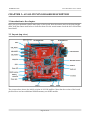
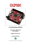
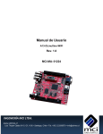
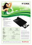
3.1 Layout (top view)
The picture above shows the initial revision of A13-OLinuXino. Note that the version of the board
pictured does not have additional NAND memory nor WIFI module.
Page 16 of 37
OLIMEX© 2015
A13-OLinuXino user's manual
CHAPTER 4: THE ALLWINNER A13 MICROCONTROLLER
4. Introduction to the chapter
In this chapter is located the information about the heart of OLinuXino – its microcontroller. The
information is a modified version of the datasheet provided by its manufacturers.
4.1 The microcontroller
CPU/GPU
ARM Cortex-A8 Core
32KB D-Cache/ 32KB I-Cache
256KB L2 Cache
Mali-400 3-D Engine
VPU
HD Video Decoding
1920*1080@30fps
Support H.264, H.263, VC1, Mpeg1/2/4
Divx 3/4/5/6, Xvid, VP6/8, AVS etc
HD Video Encoding
Support encoding in H.264 format
Up to 1920*1080 at 30fps
DPU
LCD Interfaces: CPU, RGB
Memory
DDR2/DDR3: Up to 533MHz
16 bits Data Bus
Memory capacity up to 512MB
MLC/TLC/SLC/EF-NAND
2 flash chips, ECC 64-bit
Support NAND of 5xnm, 4xnm, 3xnm, 2xnm
Support NADN of Samsung, Toshiba, Hynix
Peripherals
USB2.0 OTG, USB2.0 HOST
(OHCI/EHCI)
SD Card V.3.0, eMMC V.4.2
SPI, TWI and UART
integrated Audio Codec
CSI
Page 17 of 37
OLIMEX© 2015
A13-OLinuXino user's manual
R-TP Controller
4-wire resistive TP interface
2 points and gesture detection
Boot Devices
NAND Flash
SPI Nor Flash
SD Card
USB
Powerful Acceleration
Graphic (3D, Mali400 MP)
VPU (1080P)
APU
E-Reader
Ultra-low System Power Consumption
15~20% lower than competitors
Smart Backlight: auto adjust backlight
acc. to the image display
Package
eLQFP176
More information can be found on Allwinner's web site at the following web-address:
http://www.allwinnertech.com/product/A13.html
Page 18 of 37
OLIMEX© 2015
A13-OLinuXino user's manual
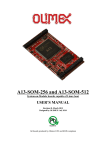
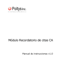
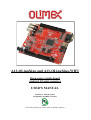
4.2 Block diagram
The block diagram is taken from Allwinner's datasheet.
Page 19 of 37
OLIMEX© 2015
A13-OLinuXino user's manual
CHAPTER 5: CONTROL CIRCUITY
5. Introduction to the chapter
Here you can find information about reset circuit and quartz crystals locations, the power supply
circuit is discussed.
5.1 Reset
The reset line is handled by the AXP209 (which is an enhanced single cell Li-battery and power
system management IC that goes together with the Allwinner processor) and goes to processor pin
159 via R4(47k). The reset circuit is connected to button RESET, which means pressing RESET
would perform a hardware reset on the board.
5.2 Clocks
24 MHz quartz crystal Q1 is connected to pins 91 and 92 of the A13 processor.
12 MHz quartz crystal Q2 is found at pins 6 and 7 of the GL850G (the USB controller).
32 768 kHz (RTC clock) quartz crystal Q3 is found connected to pins 1 and 2 of the
RTC_MODULE (PCF8563T)
5.3 Power supply circuit
The power supply is handled mainly by AXP209 power management system, an Allwinner chip that
goes together with the A13 processor. The power supply circuit of A13-OLinuXino allows flexible
input supply from 6V to 16V. The minimum amperage suggested is 1A, and this threshold would
rise if using all the three USB-HOSTs, a lot of GPIOs and LCD_con.
The board can also be powered by 3.7V Li-Po battery retaining its functionality or by USB (limiting
the use of peripherals.
Important! Avoid disconnecting the power supply while Android or Linux is running, since that
might corrupt the NAN memory (and the operating system files) and you will need to install the OS
again (for Android install instructions check chapter 2.6. Hold the PWR_BUT and then navigate to
shut down before disconnecting the supply.
Page 20 of 37
OLIMEX© 2015
A13-OLinuXino user's manual
CHAPTER 6: CONNECTORS AND PINOUT
6. Introduction to the chapter
In this chapter are presented the connectors that can be found on the board all together with their
pinout and notes about them. Jumpers functions are described. Notes and info on specific
peripherals are presented. Notes regarding the interfaces are given.
6.1 Communication with the A13
The chip has a built-in bootloader so everything you need for debugging is an USB cable. However
there is a second option which is the male UART1 connector capable of delivering some
information on the COM port of your computer. You can use USB-SERIAL-CABLE-F with the
UART1 interface allowing you to connect to an USB port.
6.1.1 USB communication
The main way of communicating with the firmware of A13-OLinuXino is via the USB-OTG
connector.
You will also need a software tool “LiveSuit” and a newer firmware image if you wish to upgrade
the firmware. The “LiveSuit” tool may be downloaded from the A13 wiki page. The simple steps
for upgrading the firmware via the bootloader are:
1. Start LiveSuit
2. Disconnect power supply cable and USB cable from A13-OLinuXino
3. Hold “Home” button
4. Connect the board to the power supply and the computer via the USB-OTG
5. Release “Home” button
6. You will be asked for drivers, point the installer to the LiveSuit folder which contains drivers for
the bootloader
7. Choose the image in the LiveSuit
8. Update and don't disconnect the board
The three USB type A hosts are wired to a USB-controller GL850G which is an advanced version
hub solution fully complying with Universal Serial Bus Specification Revision 2.0. GL850G has
proven compatibility, lower power consumption figure and better cost structure above all USB2.0
hub solutions worldwide.
Page 21 of 37
OLIMEX© 2015
A13-OLinuXino user's manual
6.1.2 UART1 interface
The UART interface might be used for COM communication. You can use our USB-SERIALCABLE-F for debugging via the UART1 or UART0. Note that in both cases the connectors are
named at the bottom of the board.
Depending on the revision of the board it is possible to have 1xUART1 or 1xUART0 + 1xUART1.
If having a board with 1xUART1 (board revision B, A13-OlinuXino-WIFI-DEV) the table with the
signals can be found below:
UART1
Pin #
Signal Name
Processor Pin #
1
3.3V
-
2
SDC0_SCK
110
3
SDC0_DATA3
112
4
GND
-
Consider the above table when connecting the USB-SERIAL-CABLE-F according to the wire color
code. If having A13-OLinuXino with 1xUART0 and the table with the signals can be found below:
UART0
Pin #
Signal Name
UART1
Processor Pin #
Pin #
Signal Name
Processor Pin #
1
3.3V
-
1
3.3V
-
2
SDC0_SCK
110
2
UART1_TX
152
3
SDC0_DATA3
112
3
UART1_RX
151
4
GND
-
4
GND
-
Consider the above table when connecting the USB-SERIAL-CABLE-F.
Notice that UART0 data lines are multiplexed with the SD-CARD.
Notice that UART1 data lines are multiplexed with the UART pins in the UEXT connector.
Page 22 of 37
OLIMEX© 2015
A13-OLinuXino user's manual
6.2 SD/MMC slot
The microSD card slot is a standard 8pin connector.
The SD card can be used for booting the operating system for A13-OLinuXino. It is suggested to
have an SD card with a proper Linux/Android image especially if you have ordered a version of the
board without NAND memory.
We have tested a number of microSD cards on the OLinuXino boards and all of them worked fine
regardless manufacturer or capacity. However, keep in mind that some of the lower quality
microSD cards might draw too much current from the slot which might cause power-state problems.
If you suspect the microSD card is causing problems please try using another one of better quality
for better results.
microSD card connector
Pin #
Signal Name
Processor Pin #
1
DAT2/RES
113
2
SDC0_DATA3
112
3
SDC0_CMD
111
4
VDD
-
5
SDC0_SCK
110
6
VSS
-
7
SDC0_DATA0
108
8
SDC0_DATA1
107
When removing the card, please make sure that you release it from the connector by pushing and
NOT by pulling the card directly (this can damage both the connector and the microSD card).
Page 23 of 37
OLIMEX© 2015
A13-OLinuXino user's manual
6.3 UEXT module
A13-OLinuXino has an UEXT connector and can connect with Olimex's UEXT modules.
For more information on UEXT please visit:
https://www.olimex.com/Products/Modules/UEXT/resources/UEXT.pdf
UEXT connector
Pin #
Signal Name
Processor Pin #
1
3.3V
-
2
GND
-
3
UART1_TX
152
4
UART1_RX
151
5
TWI2_SCK
161
6
TWI2_SDA
160
7
SPI2_MISO
117
8
SPI2_MOSI
116
9
SPI2_CLK
115
10
SPI2_CS0
114
The UEXT pinout is also printed at the bottom of the board under the connector.
Notice that UART1 data lines are multiplexed with the UART pins in the UEXT connector.
Page 24 of 37
OLIMEX© 2015
A13-OLinuXino user's manual
6.4 GPIO-1 (General Purpose Input/Output) 10pin connector
The GPIO connector numbers are printed at the bottom of the board for your convenience.
GPIO-1
Pin # Signal Name
Processor Pin #
1 5V
-
2 GND
-
3 3.3V
-
4 GND
-
5 RESET_N
159
6 NMI_N
158
7 PIN0
-
8 PIN3
-
9 PIN1
-
10 PIN2
-
PIN0, PIN1, PIN2 and PIN3 are connected to the power regulator module AXP209.
Page 25 of 37
OLIMEX© 2015
A13-OLinuXino user's manual
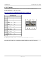
6.5 GPIO-2 (General Purpose Input/Output) 40pin connector
The GPIO pins are led out on a separate 40pin connecter. They allow the user to attach additional
hardware, check readings or perform hardware debug. The GPIO-2 connector numbers are printed
at the bottom of the board for your convenience.
GPIO Pin#
1
3
5
7
9
11
13
15
17
19
GPIO Pin#
21
23
25
27
29
31
33
35
37
39
Signal Name
5V
3.3V
PIN4/TWI0-SCK
PIN5/TWI0-SDA
PIN6
PIN7
PIN8
PIN9
PIN10/TWI1-SCK
PIN11/TWI1-SDA
Signal Name
PIN12/NWE
PIN13/NALE
PIN14/NCLE
PIN15/NCE1
PIN16/NCE0
PIN17/NRE
PIN18/NRB0
PIN19/NRB1
PIN20/NDQ0
PIN21/NDQ1
GPIO-2 connector
Processor pin#
GPIO Pin#
2
4
101
6
102
8
103
10
150
12
104
14
10
16
105
18
106
20
Processor pin#
GPIO Pin#
8
22
7
24
6
26
3
28
2
30
1
32
176
34
175
36
174
38
172
40
Page 26 of 37
Signal Name
GND
GND
PIN39/USBH_EN
PIN38/VGA_DIS
PIN37/LED1
PIN36
PIN35
PIN34
PIN33
PIN32
Signal Name
PIN31
PIN30
PIN29
PIN28/NDQS
PIN27/NDQ7
PIN26/NDQ6
PIN25/NDQ5
PIN24/NDQ4
PIN23/NDQ3
PIN22/NDQ2
Processor pin#
14
13
12
125
124
123
122
121
Processor pin#
120
119
118
162
165
166
167
168
170
171
OLIMEX© 2015
A13-OLinuXino user's manual
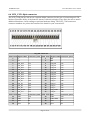
6.6 LCD_CON 40pin connector
The LCD_CON pins are led out on a separate 40pin connecter for the ease of connecting an LCD.
We have tested the ability of the board to interact with such a display. They allow the user to attach
additional hardware, check readings or perform hardware debug. The LCD_CON connectors
connector numbers are print at the bottom of the board for your convenience.
LCD_CON connector
GPIO Pin# Signal Name Processor pin#
GPIO Pin# Signal Name Processor pin#
1
5
-
2
GND
-
3
3.3
-
4
GND
-
5
LCD_D18
135
6
LCD_D18
135
7
LCD_D18
135
8
LCD_D19
134
9
LCD_D20
133
10
LCD_D21
132
11
LCD_D22
131
12
LCD_D23
130
13
LCD_D10
141
14
LCD_D10
141
15
LCD_D10
141
16
LCD_D11
140
17
LCD_D12
139
18
LCD_D13
138
19
LCD_D14
137
20
LCD_D15
136
21
LCD_D2
148
22
LCD_D2
148
23
LCD_D2
148
24
LCD_D3
147
25
LCD_D4
146
26
LCD_D5
145
27
LCD_D6
144
28
LCD_D7
143
29
LCD_HSYNC
127
30
LCD_VSYNC
126
31
LCD_CLK
129
32
LCD_DE
128
GPIO Pin# Name
Processor pin#
GPIO Pin# Name
Processor pin#
33
PIN7
150
34
PIN8
104
35
PIN9
10
36
PIN6/PWM0
109
37
TPX1
89
38
TPX2
87
39
TPY1
90
40
TPY2
88
Page 27 of 37
OLIMEX© 2015
A13-OLinuXino user's manual
6.7 PWR Jack
The power jack used is the typical one used by Olimex in most of our products – the DC barrel jack
has 2.0mm inner pin and 6.3mm hole. More information about the exact component might be found
here: https://www.olimex.com/wiki/PWRJACK. You should provide between 6 and 16 volts @
1.5A maximum to the board.
Pin #
Signal Name
1
Power Input
2
GND
More info about the power supply can be found in chapter 5 of this manual
6.8 Headphones and microphone connector
Standard audio jack and phone jack are mounted for the audio interfacing.
Microphone/Audio out connector
Pin#
SIGNAL NAME
Processor Pin#
2
L channel
74
3
R channel
78
5
HPCOM
GND pins
The headphones resistance is 32 Ohms! The mic is connected to pins 84 and 85 of the A13 chip.
Page 28 of 37
OLIMEX© 2015
A13-OLinuXino user's manual
6.9 Battery connector
When using the battery connector keep in mind that it is an energy solution that wouldn't be able to
power the board and all the peripherals. The voltage of a 3.7V LIPO battery would be enough to
power the processor and the memory but won't be enough to power external touchscreen LCD.
Pin #
Signal Name
1
VBAT
2
GND
The pins are also print at the bottom of the board under the connector.
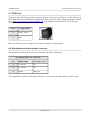
6.7 VGA video connector
The female DB15 connector is used for video output on a monitor.
At the moment the maximum achieved resolution is 800×600 due
to limited maximum frequency and the lack of integrated video
controller in the chip.
VGA connector
GPIO Pin#
Signal Name
GPIO Pin#
Signal Name
1
VGA_R
2
VGA_G
3
VGA_B
4
Not Connected
5
GND
6
GND
7
GND
8
GND
9
GND
10
GND
11
Not Connected
12
Not Connected
13
VGA_HSYNC
14
VGA_VSYNC
15
Not Connected
16
Not Connected
Page 29 of 37
OLIMEX© 2015
A13-OLinuXino user's manual
6.8 Jumper description
Please note that all the jumpers on the board are SMD type. If you feel insecure of your
soldering/cutting technique it is better not to try to adjust the jumpers. The only really important
jumper on the board is CE_NAND_E, which needs to be closed if you have board variant with
NAND flash memory but you wish to boot OS from SD card.
6.8.1 CE_NAND_E
When cut this board disconnects the NAND flash. Note that it is not a requirement to boot from the
SD card since the processor has a routine of detecting such.
The default position is closed.
6.8.2 3.3V_OPTION, 1.5V_E
Both jumpers provide a test pad during production and debugging checking the supply voltages. It
is not recommended to change their default positions.
The default positions are closed.
6.8.3 5V_E
The jumper provide a test pad during production and debugging checking the supply voltages. It is
not recommended to change its default position. It is also useful if you remove the whole battery
part of the board.
The default position is open.
6.8.4 HOST_EN, 5V_E_WIFI, WIFI-3.3V/5V_USB
These jumper provide options to setup the WIFI module to work on 3.3V, and/or the USB host to
work on 3.3V. It is strongly not recommended to change the default positions, since then they will
be directly powered from source which might cause faults of USB devices when disconnecting
them from the hub.
Default positions are:
HOST_EN – open;
5V_E_WIFI – open;
WIFI-3.3V/5V_USB in 5V_USB position.
Page 30 of 37
OLIMEX© 2015
A13-OLinuXino user's manual
6.9 Additional hardware components
The components below are mounted on OLinuXino but are not discussed above. They are listed
here for completeness:
Reset button – used to reset the board
2×2Gb (512M x 8 bit) DDR3 SDRAM – the memory used in the first revisions of the board was
HYNIX H5TQ2G83CFR; we later switched to SAMSUNG K4B2G0846Q
Please note that there are different Debian images for different boards with different hardware – you
would need to inspect the DDR3 RAM memory markings and use the image suitable for your
board. Previously we used HYNIX H5TQ2G83CFR, now we use SAMSUNG K4B2G0846Q.
1×32Gb (4096M x 8 bit) NAND FLASH – the exact memory is HYNIX H27UBG8BTR – only
present in A13-OLinuXino-WIFI
LED1 + CHLED + PWR_LED – GPIO LED + battery charger activity LED + power-on LED
Page 31 of 37
OLIMEX© 2015
A13-OLinuXino user's manual
CHAPTER 7: SCHEMATICS
7. Introduction to the chapter
In this chapter are located the schematics describing logically and physically A13-OLinuXino.
7.1 Eagle schematic
OLinuXino schematics may be found it on the OLinuXino's GitHub repository:
https://github.com/OLIMEX/OLINUXINO/tree/master/HARDWARE/A13-OLinuXino. You can
download the whole repository as .zip without having a GitHub account.
We mostly use Eagle by Cad Soft 4.16r2 for designing. However, the files should be compatible
with the latest Eagle available. Cad Soft offers a trial version of their software that allows you to
inspect schematics and board files (without being able to modify them).
This work is licensed under the Creative Commons Attribution-ShareAlike 3.0 Unported License.
To view a copy of this license, visit http://creativecommons.org/licenses/by-sa/3.0/.
If you are looking for a schematic of an older revision of the board and it isn't available at our web
site you may request it by the support e-mail.
Note that A13-OLinuXino-WIFI has all the components shown in the schematics. The stripped
down version (A13-OLinuXino, without the -WIFI part) lacks two components: the NAND
memory and the embedded WIFI module RTL8188CU. To reduce this document's size only one of
the schematics is listed.
Page 32 of 37
OLIMEX© 2015
A13-OLinuXino user's manual
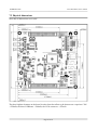
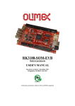
7.2 Physical dimensions
Note that all dimensions are in mils.
The three highest elements on the board in order from the tallest to the shortest are: capacitor C126
– 650mils, the three USB hosts – 500mils, the VGA connector – 475mils
Page 33 of 37
OLIMEX© 2015
A13-OLinuXino user's manual
CHAPTER 8: REVISION HISTORY AND SUPPORT
8. Introduction to the chapter
In this chapter you will find the current and the previous version of the document you are reading.
Also the web-page for your device is listed. Be sure to check it after a purchase for the latest
available updates and examples.
8.1 Document revision
Revision
Changes
Modified Page#
A, 19.09.12
Initial Creation
All
B, 21.09.12
Page 9 – Fixed several errors in voltage
requirements and power consumption
9
C, 24.09.12
Pages 8, 9 – Fixed a typo of the wattage
required
Page 11 – Added info how to change the
configuration of the Android image
8, 9, 11
D, 26.09.12
Pages 9, 19 – added important note about
powering down
Pages 13, 14 – changed the default config
file
9, 13, 14, 19
E, 31.10.12
Pages 9, 10, 37 – added info about Android
images
Page 29 – fixed erroneous information about
CE_NAND_E
Various pages – made it clear that the
standard version lacks NAND and WIFI
9, 10, 29, 37
F, 21.03.13
Pages 9, 19 – added info about LiveSuit and
cleared the instructions
Page 29 – fixed erroneous memory
descriptions
Pages 20, 22 – added some multiplexing
notes for clarity
Pages 33, 34 – updated board revisions
Various pages- updated several links
9, 19, 20, 22, 29 33, 34
G, 03.11.14
Added new Allwinner boards
Added GPIO, I2C and SPI information
Page 35 – manual revision updated
Page 36 – board revision
H, 18.02.15
Added information about different DDR3
memories and the fact that they require
different Debian image
Page 34 of 37
6, 14, 16, 36
31
OLIMEX© 2015
A13-OLinuXino user's manual
8.2 Board revision
Remember to check the schematics and the board design files to compare the differences.
Revision
Notable Changes
B
Initial release of the board
C
1. Fixed the VGA problem with development edition;
2. changed UART1 to UART0 and added new UART1;
3. added SMD jumper to be able to disable CS if you wish to boot from SD
card in future;
4. JTAG signals are on led to pads;
5. added test pads for the voltage of all regulators;
6. moved couple of elements for better distance between each other
D
1. Removed resistor matrices, except the ones near DDR3 memories – to
lower production fault rates and improve repair-ability of the boards
2. Added header NA(HN1X2) so you can power only the RTC from external
battery
3. BAT54C is added to allow RTC powering either from VDD_RTC or 3.0V_BAT
E
1. Added BAT54C after Rx to UART1 connector
2. Added 4.32k pull-up resistor on the RX line
3. Changed wrong prints of the revision and the Olimex web-site
4. Some libraries updated and some component prints removed due to space
restrictions
5. Optimization of R10, R12, R13 with (239R/1%) value to 330R/1%
F
1. Changed the SD card package with a more easier to replace one
2. Changed to package of the 32768 quartz crystal with an SMD type
G
1. Updated component libraries
2. Some of the boards might use the new SAMSUNG memory – these require
different Debian image
Page 35 of 37
OLIMEX© 2015
A13-OLinuXino user's manual
8.3 Useful web links and purchase codes
The web page you can visit for more info on your device is
https://www.olimex.com/Products/OLinuXino/A13/A13-OLinuXino-WIFI/.
A place for general questions, FAQ or friendly talk check our forums:
https://www.olimex.com/forum/
Links to some of the ready images are available in the wiki: https://www.olimex.com/wiki/A13OLinuXino
You can get the latest updates on the software at: https://github.com/OLIMEX/OLINUXINO.
ORDER CODES:
A13-OLinuXino-WIFI – the full version of A13-OLinuXino with added NAND memory (Android
image) and MOD-WIFI_RTL8188
A13-OLinuXino – the lite version of A13-OLinuXino with no external NAND and no embedded
internet interface
USB-SERIAL-CABLE-F – USB serial console cable for connecting to UART1
SY0612E – power supply adapter 12V/0.5A for A13-OLinuXino and A13-OLinuXino-WIFI
BATTERY-LIPO1400mAh – battery capable of powering A13-OLinuXino-WIFI for a couple of
hours (4+ hours standby with WiFi on)
How to order?
You can order directly from our online shop or from any of our distributors. The list of distributors
is found here: https://www.olimex.com/Distributors/.
Check https://www.olimex.com/ for more info.
Page 36 of 37
OLIMEX© 2015
A13-OLinuXino user's manual
8.4 Product support
For product support, hardware information and error reports mail to: [email protected]. All
document or hardware feedback is welcome. Note that we are primarily a hardware company and
our software support is limited. Please consider reading the paragraph below about the warranty of
Olimex products.
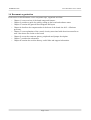
All goods are checked before they are sent out. In the unlikely event that goods are faulty,
they must be returned, to OLIMEX at the address listed on your order invoice.
OLIMEX will not accept goods that have clearly been used more than the amount needed to
evaluate their functionality.
If the goods are found to be in working condition, and the lack of functionality is a result of
lack of knowledge on the customers part, no refund will be made, but the goods will be returned
to the user at their expense.
All returns must be authorized by an RMA Number. Email [email protected] for authorization
number before shipping back any merchandise. Please include your name, phone number and order
number in your email request.
Returns for any unaffected development board, programmer, tools, and cables permitted within 7
days from the date of receipt of merchandise. After such time, all sales are considered final.
Returns of incorrect ordered items are allowed subject to a 10% restocking fee. What is
unaffected? If you hooked it to power, you affected it. To be clear, this includes items that
have been soldered to, or have had their firmware changed. Because of the nature of the
products we deal with (prototyping electronic tools) we cannot allow returns of items that have
been programmed, powered up, or otherwise changed post shipment from our warehouse.
All returned merchandise must be in its original mint and clean condition. Returns on damaged,
scratched, programmed, burnt, or otherwise 'played with' merchandise will not be accepted.
All returns must include all the factory accessories which come with the item. This includes
any In-Circuit-Serial-Programming cables, anti-static packing, boxes, etc.
With your return, enclose your PO#. Also include a brief letter of explanation of why the
merchandise is being returned and state your request for either a refund or an exchange.
Include the authorization number on this letter, and on the outside of the shipping box.
Please note: It is your responsibility to ensure that returned goods reach us. Please use a
reliable form of shipping. If we do not receive your package we will not be held liable.
Shipping and handling charges are not refundable. We are not responsible for any shipping
charges of merchandise being returned to us or returning working items to you.
The full text might be found at https://www.olimex.com/wiki/GTC#Warranty for future reference.
Page 37 of 37