1
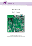
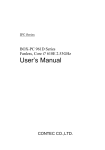
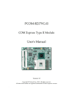
PCOM-B216VG-VI
COM Express Type VI Module
User's Manual
Version 1.0
Copyright © Portwell, Inc., 2010. All rights reserved.
All other brand names are registered trademarks of their respective owners.
Preface
How to Use This Manual
The manual describes how to configure your PCOM-B216VG-VI to meet various
operating requirements. It is divided into five chapters, with each chapter addressing
a basic concept and operation of this COM Express Module.
Chapter 1 : System Overview. Presents what you have in the box and give you an
overview of the product specifications and basic system architecture for this model of
single board computer.
Chapter 2 : Hardware Configuration. Shows the definition and location of Jumpers
and Connectors that you can easily configure your system.
Chapter 3 : System Installation. Describes how to properly mount the CPU, main
memory to get a safe installation and provides a programming guide of Watch Dog
Timer function.
Chapter 4 : BIOS Setup Information. Specifies the meaning of each setup
parameters, how to get advanced BIOS performance and update new BIOS. In
addition, POST checkpoint list will give users some guidelines of trouble-shooting.
The content of this manual and EC declaration document is subject to change without
prior notice. These changes will be incorporated in new editions of the document.
Portwell may make supplement or change in the products described in this
document at any time.
Updates to this manual, technical clarification, and answers to frequently asked
questions will be shown on the following web site: http://www.portwell.com.tw
Chapter 1
System Overview
1.1
Introduction
COM Express Type 6, have not holds by PICMG (PCI Industrial Computer
Manufacturer Group) yet but they will defines new industrial computer platform in
“Module board” and “Carrier board” architecture. The “Module board” equipped
processor or its socket, chipset, memory or memory socket and single Ethernet
controller on it. The On-The-Shelf Module board allows users to create their own
Carrier board easily and quickly since most critical parts are ready on Module board.
COM Express Module board offers expansion interfaces such as PCI Express, PCI,
SATA, IDE, LPC, LVDS, HDMI, DP, DVI, and Audio etc. that could support variety
functions depending on Carrier board design.
The Carrier board was customized design to fit in different mechanical requirements.
In the meanwhile, its variety functions were also customized to meet the application.
Compares to the platform that designed from nothing, COM Express architecture
platform only needs to develop Carrier board. Users could keep their know-how
which related to their core competence in the Carrier board.
PCOM-B216VG-VI is Type VI COM Express Module board equipped Intel Arrandale
BGA processor (Core i7-610E/ i7-620LE/ i7-620UE/ Core i5-520E and Celeron P4505
processor on-board), two DDR3 SO-DIMM sockets, one Gigabit Ethernet controller
on it to provide expansion interfaces – PCI Express (x16 / x1), Three Multiple display
ports (supports SDVO/HDMI/DP/DVI), SATA and so on.
1.2
Check List
The PCOM-B216VG-VI series package should cover the following basic items
One PCOM-B216VG-VI module board
If any of these items is damaged or missing, please contact your vendor and keep all
packing materials for future replacement and maintenance.
PCOM-B216VG-VI User’s Manual
1.3
Product Specification
Main processor
- Intel® Core i7-610E
SV
Core i7-620LE
LV
Core i7-620UE
ULV
Core i5-520E
SV
Celeron P4505
SV
- DMI x4 Link: 4.8GT/s (Full-Duplex)
(4M Cache, 2.53GHz)
(4M Cache, 2.00GHz)
(4M Cache, 1.06GHz)
(3M Cache, 2.40GHz)
(2M Cache, 1.86GHz)
BIOS
AMI UEFI Aptio system BIOS in SPI ROM with 4MB Flash ROM with easy
upgrade function ACPI, DMI, Green function and Plug and Play Compatible
Main Memory
Two SO-DIMM sockets support dual channel DDR3 800/1066 up to 8GB
L2 Cache Memory
Build-in processor
Chipset
Intel QM57 chipset
Expansion Interfaces
- PCI Express
One PCI Express x16 link
Seven PCI Express x1 link
- LVDS
Supports 25 to 112MHz single/dual channel LVDS interface
Single channel LVDS interface support: 1 x 18 bpp or 24 bpp,
compatible with VESA LVDS color mapping.
Dual channel LVDS interface support: 2 x 18 bpp or 24 bpp
Compatible with SPWG(Standard Panels Working Group) v.3.5 specification
- SDVO (Serial Digital Video Output)
One SDVO ports are supported (multiplex pins with HDMI/DP at Port B)
- VGA
Up to 2048 x 1536 mode support
- Ethernet
Intel 82577LM Gigabit Ethernet controller is equipped, 4 MDI pairs on Row
A- B
- SATA Interface
Support Three SATA 300 ports and one eSATA port
- USB Interface
PCOM-B216VG-VI User’s Manual
Support eight USB 2.0 ports
Outline Dimension (L X W):
95mm (3.74”) X 125mm (4.92”)
Operating Temperature:
0°C ~ 60°C (32°F ~ 140°F)
Storage Temperature:
-20°C ~ 80°C
Relative Humidity:
5% ~ 90%, non-condensing
PCOM-B216VG-VI User’s Manual
1.4
Mechanical Drawing
PCOM-B216VG-VI User’s Manual
1.5
System Architecture
PCOM-B216VG-VI Series System Block Diagram
PCOM-B216VG-VI User’s Manual
Chapter 2
Hardware Configuration
This chapter indicates jumpers’, headers’ and connectors’ locations. Users may find
useful information related to hardware settings in this chapter. The default settings
are indicated with a star sign ().
2.1
Jumper Setting
In order to customize PCOM-B216VG-VI’s features for users, in the following
sections, Short means covering a jumper cap over jumper pins; Open or N/C (Not
Connected) means removing a jumper cap from jumper pins. Users can refer to
Figure 2-1 and Figure 2-2 for the Jumper locations.
Figure 2-1 PCOM-B216VG-VI Top-side Connector Location
PCOM-B216VG-VI User’s Manual
Figure 2-2 PCOM-B216VG-VI Bottom-side Connector Location
PCOM-B216VG-VI User’s Manual
2.2
Connector Allocation
Connector Function List
Connector
Function
U28
DDR3 channel A connector.
To enable IAMT function, memory module must
install to this connector if one RAM module
only.
U2
DDR3 channel B connector.
J3
COM Express connector raw A and B
J2
COM Express connector raw C and D
Remark
Pin Assignment of Connectors
J3
Pin No
A1
A2
A3
A4
A5
A6
A7
A8
A9
A10
A11
A12
A13
A14
Row A
Signal Description
GND (FIXED)
GBE0_MDI3GBE0_MDI3+
GBE0_LINK100#
GBE0_LINK1000#
GBE0_MDI2GBE0_MDI2+
GBE0_LINK#
GBE0_MDI1GBE0_MDI1+
GND (FIXED)
GBE0_MDI0GBE0_MDI0+
GBE0_CTREF
SUS_S3#
A15
Pin No
B1
B2
B3
B4
B5
B6
B7
B8
B9
B10
B11
B12
B13
B14
SATA0_TXSUS_S4#
SATA0_RX+
SATA0_RXGND (FIXED)
SATA2_TX+
SATA2_TXSUS_S5#
SATA2_RX+
SATA2_RX-
A26
A29
B16
B17
B18
B19
B20
B21
B22
B23
B24
B25
B27
B28
GND (FIXED)
HDA_BITCLK
HDA_SDIN2
HDA_SDIN1
B32
HDA_SDOUT
BIOS_DISABLE#
C27
C28
C29
GND (FIXED)
SPKR
C30
C31
PCOM-B216VG-VI User’s Manual
DP1_AUX#
SDVO1_TVCLKIN
+
SDVO1_TVCLKIN
GND (FIXED)
DP2_AUX
I2C_DAT
RSVD
D16
D17
D18
D19
D20
D21
D22
D23
D24
D25
D27
D28
D29
D30
D31
D32
DP2_AUX#
C33
C34
Row D
Signal Description
GND (FIXED)
GND
USB0_SSTXUSB0_SSTX+
GND
USB1_SSTXUSB1_SSTX+
GND
USB2_SSTXUSB2_SSTX+
GND (FIXED)
USB3_SSTXUSB3_SSTX+
GND
RSVD
D15
D26
C32
I2C_CK
B33
B34
Pin No
D1
D2
D3
D4
D5
D6
D7
D8
D9
D10
D11
D12
D13
D14
DP1_AUX
HDA_SDIN0
B30
B31
Row C
Signal Description
GND (FIXED)
GND
USB0_SSRXUSB0_SSRX+
GND
USB1_SSRXUSB1_SSRX+
GND
USB2_SSRXUSB2_SSRX+
GND (FIXED)
USB3_SSRXUSB3_SSRX+
GND
SDVO1_FLDSTAL
L+
SDVO1_FLDSTAL
LRSVD
RSVD
PCIE_RX6+
PCIE_RX6GND (FIXED)
PCIE_RX7+
PCIE_RX7DP1_HPD
SDVO1_INT+
SDVO1_INT-
C26
B29
A32
A33
A34
SATA1_TXSUS_STAT#
SATA1_RX+
SATA1_RXGND (FIXED)
SATA3_TX+
SATA3_TXPWR_OK
SATA3_RX+
SATA3_RX-
C16
C17
C18
C19
C20
C21
C22
C23
C24
C25
WDT
AHDA_RST#
A30
A31
C15
B26
ATA_ACT#
HDA_SYNC
Pin No
C1
C2
C3
C4
C5
C6
C7
C8
C9
C10
C11
C12
C13
C14
SATA1_TX+
BATLOW#
A27
A28
Row B
Signal Description
GND (FIXED)
GBE0_ACT#
LPC_FRAME#
LPC_AD0
LPC_AD1
LPC_AD2
LPC_AD3
LPC_DRQ0#
LPC_DRQ1#
LPC_CLK
GND (FIXED)
PWRBTN#
SMB_CK
SMB_DAT
SMB_ALERT#
B15
SATA0_TX+
A16
A17
A18
A19
A20
A21
A22
A23
A24
A25
J2
D33
HDMI2_CLRLCLK D34
RSVD
RSVD
PCIE_TX6+
PCIE_TX6GND (FIXED)
PCIE_TX7+
PCIE_TX7RSVD
RSVD
DP1_LANE0/SDVO1_
RE D+
DP1_LANE0#/SDVO1_
RE DRSVD
DP1_LANE1/SDVO1_
GR N+
DP1_LANE1#/SDVO1
_G RNGND (FIXED)
DP1_LANE2/SDVO1_
BL U+
DP1_LANE2#/SDVO1_
BL UHDMI2_CLRLDATA
A35
THRMTRIP#
USB6-
A36
B35
B36
USB6+
A37
A38
A39
A40
A41
A42
A43
A44
A45
A46
A47
A48
A49
A50
A51
A52
A53
A54
A55
A56
A57
A58
A59
A60
A61
A62
A63
A64
A65
A66
A67
A68
A69
A70
A71
A72
A73
A74
A75
A76
A77
A78
A79
A80
A81
A82
A83
A84
A85
A86
A87
A88
A89
A90
A91
A92
A93
A94
A95
A96
A97
A98
A99
THRM#
USB7-
USB_6_7_OC#
USB4USB4+
GND (FIXED)
USB2USB2+
USB_2_3_OC#
USB0USB0+
VCC_RTC
EXCD0_PERST#
EXCD0_CPPE#
LPC_SERIRQ
GND (FIXED)
PCIE_TX5+
PCIE_TX5GPI0
PCIE_TX4+
PCIE_TX4GND
PCIE_TX3+
PCIE_TX3GND (FIXED)
PCIE_TX2+
PCIE_TX2GPI1
PCIE_TX1+
PCIE_TX1GND
GPI2
PCIE_TX0+
PCIE_TX0GND (FIXED)
LVDS_A0+
LVDS_A0LVDS_A1+
LVDS_A1LVDS_A2+
LVDS_A2LVDS_VDD_EN
LVDS_A3+
LVDS_A3GND (FIXED)
LVDS_A_CK+
LVDS_A_CKLVDS_I2C_CK
LVDS_I2C_DAT
GPI3
KBD_RST#
KBD_A20GATE
PCIE0_CK_REF+
PCIE0_CK_REFGND (FIXED)
SPI_CS0#
SPI_MISO
GPO0
SPI_CLK
SPI_MOSI
GND
VCC_12V
VCC_12V
VCC_12V
C35
C36
USB7+
B37
B38
B39
B40
B41
B42
B43
B44
B45
B46
B47
B48
B49
B50
B51
B52
B53
B54
B55
B56
B57
B58
B59
B60
B61
B62
B63
B64
B65
B66
B67
B68
B69
B70
B71
B72
B73
B74
B75
B76
B77
B78
B79
B80
B81
B82
B83
B84
B85
B86
B87
B88
B89
B90
B91
B92
B93
B94
B95
B96
B97
B98
B99
PCOM-B216VG-VI User’s Manual
RSVD
DP3_AUX
USB_4_5_OC#
USB5USB5+
GND (FIXED)
USB3USB3+
USB_0_1_OC#
USB1USB1+
EXCD1_PERST#
EXCD1_CPPE#
SYS_RESET#
CB_RESET#
GND (FIXED)
PCIE_RX5+
PCIE_RX5GPO1
PCIE_RX4+
PCIE_RX4GPO2
PCIE_RX3+
PCIE_RX3GND (FIXED)
PCIE_RX2+
PCIE_RX2GPO3
PCIE_RX1+
PCIE_RX1WAKE0#
WAKE1#
PCIE_RX0+
PCIE_RX0GND (FIXED)
LVDS_B0+
LVDS_B0LVDS_B1+
LVDS_B1LVDS_B2+
LVDS_B2LVDS_B3+
LVDS_B3LVDS_BKLT_EN
GND (FIXED)
LVDS_B_CK+
LVDS_B_CKLVDS_BKLT_CTRL
VCC_5V_SBY
VCC_5V_SBY
VCC_5V_SBY
VCC_5V_SBY
SPI_CS1#
VGA_RED
GND (FIXED)
VGA_GRN
VGA_BLU
VGA_HSYNC
VGA_VSYNC
VGA_I2C_CK
VGA_I2C_DAT
RSVD
RSVD
RSVD
D35
D36
DP3_AUX#
C37
C38
C39
C40
C41
C42
C43
C44
C45
C46
C47
C48
C49
C50
C51
C52
C53
C54
C55
C56
C57
C58
C59
C60
C61
C62
C63
C64
C65
C66
C67
C68
C69
C70
C71
C72
C73
C74
C75
C76
C77
C78
C79
C80
C81
C82
C83
C84
C85
C86
C87
C88
C89
C90
C91
C92
C93
C94
C95
C96
C97
C98
C99
HDMI3_CLTRCLK
DP3_LANE0
DP3_LANE0#
GND (FIXED)
DP3_LANE1
DP3_LANE1#
DP3_HPD
RSVD
DP3_LANE2
DP3_LANE2#
RSVD
DP3_LANE3
DP3_LANE3#
GND (FIXED)
PEG_RX0+
PEG_RX0TYPE0#
PEG_RX1+
PEG_RX1TYPE1#
PEG_RX2+
PEG_RX2GND (FIXED)
PEG_RX3+
PEG_RX3RSVD
RSVD
PEG_RX4+
PEG_RX4RSVD
PEG_RX5+
PEG_RX5GND (FIXED)
PEG_RX6+
PEG_RX6SDVO_DATA
PEG_RX7+
PEG_RX7GND
RSVD
PEG_RX8+
PEG_RX8GND (FIXED)
PEG_RX9+
PEG_RX9RSVD
GND
PEG_RX10+
PEG_RX10GND
PEG_RX11+
PEG_RX11GND (FIXED)
PEG_RX12+
PEG_RX12GND
PEG_RX13+
PEG_RX13GND
RSVD
PEG_RX14+
PEG_RX14-
D37
D38
D39
D40
D41
D42
D43
D44
D45
D46
D47
D48
D49
D50
D51
D52
D53
D54
D55
D56
D57
D58
D59
D60
D61
D62
D63
D64
D65
D66
D67
D68
D69
D70
D71
D72
D73
D74
D75
D76
D77
D78
D79
D80
D81
D82
D83
D84
D85
D86
D87
D88
D89
D90
D91
D92
D93
D94
D95
D96
D97
D98
D99
RSVD
DP1_LANE3/SDVO1_C
K
DP1_LANE3#/SDVO1
_C KHDMI3_CTRLDATA
DP2_LANE0
DP2_LANE0#
GND (FIXED)
DP2_LANE1
DP2_LANE1#
DP2_HPD
RSVD
DP2_LANE2
DP2_LANE2#
RSVD
DP2_LANE3
DP2_LANE3#
GND (FIXED)
PEG_TX0+
PEG_TX0PEG_LANE_RV#
PEG_TX1+
PEG_TX1TYPE2#
PEG_TX2+
PEG_TX2GND (FIXED)
PEG_TX3+
PEG_TX3RSVD
RSVD
PEG_TX4+
PEG_TX4GND
PEG_TX5+
PEG_TX5GND (FIXED)
PEG_TX6+
PEG_TX6SDVO_CLK
PEG_TX7+
PEG_TX7GND
IDE_CBLID#
PEG_TX8+
PEG_TX8GND (FIXED)
PEG_TX9+
PEG_TX9RSVD
GND
PEG_TX10+
PEG_TX10GND
PEG_TX11+
PEG_TX11GND (FIXED)
PEG_TX12+
PEG_TX12GND
PEG_TX13+
PEG_TX13GND
PEG_ENABLE#
PEG_TX14+
PEG_TX14-
A100
A101
A102
A103
A104
A105
A106
A107
A108
A109
A110
GND (FIXED)
VCC_12V
VCC_12V
VCC_12V
VCC_12V
VCC_12V
VCC_12V
VCC_12V
VCC_12V
VCC_12V
GND (FIXED)
B100
B101
B102
B103
B104
B105
B106
B107
B108
B109
B110
PCOM-B216VG-VI User’s Manual
GND (FIXED)
VCC_12V
VCC_12V
VCC_12V
VCC_12V
VCC_12V
VCC_12V
VCC_12V
VCC_12V
VCC_12V
GND (FIXED)
C100
C101
C102
C103
C104
C105
C106
C107
C108
C109
C110
GND (FIXED)
PEG_RX15+
PEG_RX15GND
VCC_12V
VCC_12V
VCC_12V
VCC_12V
VCC_12V
VCC_12V
GND (FIXED)
D100
D101
D102
D103
D104
D105
D106
D107
D108
D109
D110
GND (FIXED)
PEG_TX15+
PEG_TX15GND
VCC_12V
VCC_12V
VCC_12V
VCC_12V
VCC_12V
VCC_12V
GND (FIXED)
Chapter 3
System Installation
This chapter could provide you with instructions to set up your system. The
additional information is enclosed to help you for setting up on-board device.
3.1
Intel®CoreTM i7-610E/620LE/620UE, i5-520E, Celeron P4505
BGA processor
Configuring System Bus
PCOM-B216VG-VI series support SV/LV/ULV processor:
Intel ® Core i7-610E Processor,
Intel ® Core i7-620LE Processor,
Intel ® Core i7-620UE Processor,
Intel ® Core i5-520E Processor,
Intel ® Celeron P4505 Processor,
3.2
Main Memory
PCOM-B216VG-VI provide 2 x 204pin SO-DIMM sockets which supports
800/1066 DDR3-SDRAM as main memory, Non-ECC (Error Checking and
Correcting), non-register functions. The maximum memory can be up to 8GB.
Memory clock and related settings can be detected by BIOS via SPD interface.
For system compatibility and stability, do not use memory module without
brand. Memory configuration can be set to either one double-sided DIMM in one
DIMM socket or two single-sided SO-DIMM in both sockets.
Beware of the connection and lock integrity from memory module to socket.
Inserting improperly it will affect the system reliability.
Before locking, make sure that all modules have been fully inserted into the card
slots.
Memory Frequency
800
1066
Single Channel DDR
Bandwidth
12.8 GB/s
17 GB/s
Note:
To insure the system stability, please do not change any of DRAM parameters in
BIOS setup to modify system the performance without acquired technical
information.
PCOM-B216VG-VI User’s Manual
3.3
Installing System
To install your PCOM-B216VG-VI into standard chassis or proprietary
environment, please perform the following:
Step 1: Check all jumpers setting on proper position
Step 2: Install and configure CPU and memory module on right position
Step 3: Place PCOM-B216VG-VI into the dedicated position in the system
Step 4: Attach cables to existing peripheral devices and secure it
WARNING
Please ensure that SBC is properly inserted and fixed by mechanism.
Note:
Please refer to section 3.3.1 to 3.3.7 to install INF/VGA/LAN/Audio drivers.
Chipset Component Driver
PCOM-B216VG-VI uses state-of-art Intel® QM57 chipset. It’s a new chipset that some
old operating systems might not be able to recognize. To overcome this compatibility
issue, for Windows Operating Systems such as Windows 2000 /XP, please install its
INF before any of other Drivers are installed. You can find very easily this chipset
component driver in PCOM-B216VG-VI CD-title.
Intel Integrated Graphics GMCH Chip
PCOM-B216VG-VI uses Intel® QM57 integrated graphic chipset to gain an
outstanding graphic performance. Shared 8 accompany it to 128MB system
DDR3-SDRAM with Total Graphics Memory. PCOM-B216VG-VI supports VGA,
DVI, LVDS and LVDS dual display. This combination makes PCOM-B216VG-VI an
excellent piece of multimedia hardware.
With no additional video adaptor, this onboard video will usually be the system
display output. By adjusting the BIOS setting to disable on-board VGA, an add-on
PCI-Express by 1 VGA card can take over the system display.
PCOM-B216 User’s Manual
PCOM-B216VG-VI User’s Manual
System Installation
Drivers Support
Please find all the drivers in the PCOM-B216VG-VI CD-title. Drivers support
Windows-2000, Windows XP.
Intel® PROSet Gigabit Ethernet Controller
Drivers Support
Please find INTEL 82577LM LAN driver in /Ethernet directory of
PCOM-B216VG-VI CD-title. The drivers support Windows 2000 /XP/Vista/Win7.
Audio Controller
Please find Intel® High Definition Audio driver form PCOM-B216VG-VI
CD-title. The drivers support Windows 2000 /XP/Vista/Win7.
Intel® Active Management Technology (Intel® AMT)
Please find the latest Intel® 6.0 driver from PCOM-B216VG-VI CD-title. The
drivers support Windows 2000 /XP/Vista/Win7.
3.4
Clear CMOS Operation
There is no backup battery design on module, therefore, all settings will be lost if
disconnect PCOM-B216VG-VI Series with its carrier board.
PCOM-B216VG-VI User’s Manual
Chapter 4
BIOS Setup Information
PCOM-B216VG-VI is equipped with the AMI UEFI Aptio BIOS stored in Flash ROM.
These BIOS has a built-in Setup program that allows users to modify the basic system
configuration easily. This type of information is stored in CMOS RAM so that it is
retained during power-off periods. When system is turned on, PCOM-B216VG-VI
communicates with peripheral devices and checks its hardware resources against the
configuration information stored in the CMOS memory. If any error is detected, or
the CMOS parameters need to be initially defined, the diagnostic program will
prompt the user to enter the SETUP program. Some errors are significant enough to
abort the start up.
4.1
Entering Setup -- Launch System Setup
Power on the computer and the system will start POST (Power On Self Test) process.
When the message below appears on the screen, press <Del> key will enter BIOS
setup screen
Press <Del> to enter SETUP
If the message disappears before responding and still wish to enter Setup, please
restart the system by turning it OFF and On or pressing the RESET button. It can be
also restarted by pressing <Ctrl>, <Alt>, and <Delete> keys on keyboard
simultaneously.
Press <F1> to Run SETUP or Resume
The BIOS setup program provides a General Help screen. The menu can be easily
called up from any menu by pressing <F1>. The Help screen lists all the possible keys
to use and the selections for the highlighted item. Press <Esc> to exit the Help screen.
PCOM-B216VG-VI User’s Manual
4.2
Main
Use this menu for basic system configurations, such as time, date etc.
BIOS Information, Memory Information
These items show the firmware and momory specifications of your system. Read
only.
System Time
The time format is <Hour> <Minute> <Second>. Use [+] or [-] to configure system
Time.
System Date
The date format is <Day>, <Month> <Date> <Year>. Use [+] or [-] to configure
system Date.
PCOM-B216VG-VI User’s Manual
4.3
Advanced
Use this menu to set up the items of special enhanced features.
Launch PXE OpROM
Enable of Disable Boot Option for Lagacy Network Devices.
Choices: Disabled, Enabled
Launch Storage OpROM
Enable of Disable Boot Option for Lagacy Mass Storage devices.
Choices: Disabled, Enabled
PCOM-B216VG-VI User’s Manual
PCI Susystems Settings
PCI ROM Priority
Choices: Legacy ROM, EFI Compatible ROM
PCI Latency Timer
Choices: 32 PCI, 64 PCI, 96 PCI, 128 PCI, 160 PCI, 192 PCI, 224 PCI, 248 PCI Bus
Clocks
VGA Palette Snoop
Choices: Disabled, Enabled
PERR# Generation
Choices: Disabled, Enabled
SERR# Generation
Choices: Disabled, Enabled
Relaxed Ordering
Choices: Disabled, Enabled
Extended Tag
Choices: Disabled, Enabled
No Snoop
Choices: Disabled, Enabled
Maximum Payload
Choices: Auto, 128 Bytes, 256 Bytes, 512 Bytes, 1024 Bytes, 2048 Bytes, 4096 Bytes
PCOM-B216VG-VI User’s Manual
Maximum Read Request
Choices: Auto, 128 Bytes, 256 Bytes, 512 Bytes, 1024 Bytes, 2048 Bytes, 4096 Bytes
ASPM Support
Choices: Disabled. Auto, Force L0
Extended Synch
Choices: Disabled, Enabled
ACPI Settings
Enable ACPI Auto Configuration
Choices: Enabled, Disabled.
Enable Hiberrnation
Choices: Enabled, Disabled.
ACPI Sleep State
Choices: Suspend Disabled, S1 (CPU Stop Clock), S3 (Suspend to RAM)
PCOM-B216VG-VI User’s Manual
Trusted Computing
TPM SUPPORT
Choices: Enabled, Disabled
S5 RTC Wake Settings
PCOM-B216VG-VI User’s Manual
Wake System with Fixed Time
Choices: Disabled, Enabled
Wake up hour
Choices: 0-23
Wake up minute
Choices: 0-59
Wake up second
Choices: 0-59
CPU Configuration
These items show the advanced specifications of your CPU. Read only.
Hyper-Threading
Choices: Disabled, Enabled.
Active Processor Cores
Choices: All, 1, 2
Limit CPUID Maximum
Disabled for Windows XP
Choices: Disabled, Enabled.
PCOM-B216VG-VI User’s Manual
Hardware Prefetcher
For UP platforms, leave it enabled. For DP/MP servers, it may use to tune
performance the specific application.
Choices: Disabled, Enabled.
Adjacent Cache Line Prefetch
For UP platforms, leave it enabled. For DP/MP servers, it may use to tune
performance the specific application.
Choices: Disabled, Enabled.
Intel Virtualization Technology
Choices: Disabled, Enabled.
Power Technology
Choices: Disabled, Energy Efficient, Custom
TDC Limit
Turbo-XE Mode Processor TDC Limit in 1/8 A granularity, 0 means using the
factory-configured value.
TDP Limit
Turbo-XE Mode Processor TDP Limit in 1/8 W granularity, 0 means using the
factory-configured value.
PCOM-B216VG-VI User’s Manual
SATA Configuration
The SATA Configuration the SATA devices, such as hard disk drive or CD-ROM
drive.
SATA Mode
This setting specifies the function of the on-chip SATA controller.
Choices: Disabled, IDE Mode, RAID Mode, AHCI Mode.
Serial_ATA Controller 0
Choices: Disabled, Compatible, Enabled.
Serial_ATA Controller 1
Choices: Disabled, Compatible, Enabled.
PCOM-B216VG-VI User’s Manual
Intel IGD SWSCI OpRegion
These option contains all the Intel® IGD setting for graphic output
DVMT/FIXED Memory
Choices: 128M, 256MB, Maximum
IGD – Boot Type
Select the Video Device which will be activated during POST.
Choices: VBIOS Default, CRT, HDMI, LVDS, CRT+DVI, CRT+HDMI
LCD Panel Type
Choices: VBIOS Default, 800x600 LVDS, 1024x768 LVDS, 1280x1024 LVDS, 1400x1050
LVDS1, 1400x1050 LVDS2, 1600x1200 LVDS, 1280x768 LVDS, 1680x1050 LVDS,
1920x1200 LVDS, 1600x900 LVDS, 1280x800 LVDS, 1280x600 LVDS, 2048x1536 LVDS
Panel Scaling
Choices: Auto, Force Scaling, Off, Maintain Aspect Ratio.
Backlight Control
Choices: PWM Intverted, PWM Normal, GMBus Inverted, GMBus Normal.
BIA Control
Choices: VBIOS Default, Disabled, From Level 1 to Level 5.
Spread Spectrum Clock Chip
Choices: Off, Hardware, Software
PCOM-B216VG-VI User’s Manual
ALS Support
Choices: Disabled, Enabled.
Gfx Low Power Mode
Choices: Disabled, Enabled.
Active LFP
Choices: No LVDS, Int-LVDS, SDVO LVDS, eDP Port-A, eDP Port-D
Panel Color Depth
Choices: 18 Bit, 24 Bit
Intel TDT(AT-p) Configurations
Inter Theft Deterrence Technology Configuration
TDT
Choices: Disabled, Enabled.
TDT Recovery
Choices: 1-64
PCOM-B216VG-VI User’s Manual
Intel TXT(LT) Configuration.
Intel® Trusted Execution Technology Configuration.
Intel TXT(LT) Support
Choices: Disabled, Enabled.
USB Configuration
PCOM-B216VG-VI User’s Manual
Legacy USB Support
Set to [Enabled] if you need to use any USB 1.1/2.0 device in the operating system
that does not support or have any USB 1.1/2.0 driver installed, such as DOS and SCO
Unix.
Choices: Disabled, Enabled, Auto.
EHCI Hand-Off
This is a workaround for OSes without EHCI hand-off support. The EHCI ownership
change should claim by EHCI driver.
Choices: Disabled, Enabled.
Device Reset timeout
Choices: 10 sec, 20 sec, 30 sec, 40 sec
Super IO Configuration
List all the option that can be set of Super I/O.
Including Serial Port 0 Configuration, Watchdog Timer, Smart Fan Control
PCOM-B216VG-VI User’s Manual
Serial Port 0 Configuration
Serial Port
Choices: Disabled, Enabled,
Change Settings
Choices: Auto. IO=3F8h; IRO=4, IO=3F8h; IRO=3,4,5,6,7,10,11,12, IO=2F8h;
IRO=3,4,5,6,7,10,11,12,
IO=3E8h;
IRO=3,4,5,6,7,10,11,12,
IO=2F8h;
IRO=3,4,5,6,7,10,11,12,
Device Mode
Choices: Standard Serial Port Mode, IrDA 1.0 (HP SIR) mode, ASKIR Mode
Watchdog Timer
PCOM-B216VG-VI User’s Manual
WDT Controller
Choices: Disabled, Enabled,
Change Settings
Choices: WDT Disabled, 10, 20, 30, 40, 50, 60 seconds.
Smart Fan Control
There options will allow to change the setting of Smart Fan function of CPU, System
fans.
Smart Fan1 Control
Choices: Disabled, Enabled,
Smart Fan2 Control
Choices: Disabled, Enabled,
Smart Fan2 Start
Choices: 60, 65, 70, 75
Fan2 Full Speed
Choices: 60, 65, 70, 75
Smart Fan3 Control
Choices: Disabled, Enabled,
Smart Fan3 Start
Choices: 60, 65, 70, 75
Fan3 Full Speed
PCOM-B216VG-VI User’s Manual
Choices: 60, 65, 70, 75
Hardware Health Configuration
Configuration / Monitor the Hardware Health. Read only.
Thermal Configuration
PCOM-B216VG-VI User’s Manual
Platform Thermal Configuration
ME SMBus Thermal Reporting
Choices: Disabled, Enabled,
SMBus Buffer Length
Choices: 1,2,5,9,10,14,20
Thermal Reporting EC PEC
Choices: Disabled, Enabled,
Select Slots with TS on DIMM
Choices: NO TS on DIMM. TS on DIMM in Slot SODIMM0, TS on DIMM in Slot
SODIMM1, TS on DIMM in Slot SODIMM0 and SODIMM1
MCH Temp Read
Choices: Disabled, Enabled,
PCH Temp Read
Choices: Disabled, Enabled,
CPU Energy Read
Choices: Disabled, Enabled,
Alert Enable Lock
Choices: Disabled, Enabled,
PCOM-B216VG-VI User’s Manual
CPU Alert
Choices: Disabled, Enabled,
MCH Alert
Choices: Disabled, Enabled,
PCH Alert
Choices: Disabled, Enabled,
DIMM Alert
Choices: Disabled, Enabled,
Intelligent Power Sharing
Intelligent Power Sharing
Choices: Disabled, Enabled,
MCH Turbo
Choices: Disabled, Enabled,
PPEC Config
Processor Power Error Correction
Choices: 1 to 50
PCOM-B216VG-VI User’s Manual
IPS Policy
Choices: DRIVER, PROCESSOR, BALANCED, GRAPHICS
Core Temp Limit
Choices: Disabled, Enabled,
MCH Power Limit
Choices: Disabled, Enabled,
Processor Power Limit
Choices: Disabled, Enabled,
Core Power Limit
Choices: Disabled, Enabled,
Run Time Interface
Choices: BIOS with MMIO, EC uses SMBug
AMT Configuration
AMT
Choices: Disabled, Enabled,
Unconfigure AMT/ME
Choices: Disabled, Enabled,
WatchDog Timer
PCOM-B216VG-VI User’s Manual
Choices: Disabled, Enabled
Serial Port Console Redirection
Console Redirection
Choices: Disabled, Enabled,
Terminal Type
Choices: VT100, VT100+, VT-uTF8, ANSI
PCOM-B216VG-VI User’s Manual
4.4
Chipset
This menu controls the advanced features of the onboard Northbridge and
Southbridge.
Enable CRID
Choices: Disabled, Enabled,
PCOM-B216VG-VI User’s Manual
North Bridge Chipset Configuration
CPU & Memory status shows in North Bridge, Read only.
PCOM-B216VG-VI User’s Manual
Low MMIO Align
Choices: 64MB/1024MB
Initate Graphic Adapter
Select which graphics controller to use as the primary boot device.
Choices: IGD, PCI/IGD, PCI/PEG, PEG/IGD, PEG/PCI.
Graphics Turbo IMON Current
Choices: 14-31
VT-d
Choices: Disabled, Enabled.
PCI Express Compliance Mode
Choices: Disabled, Enabled,
PCI Express Port
Choices: Disabled, Enabled, Auto
IGD Memory
Choices: Disabled, 32M, 64M, 128M
PAVP Mode
Choices: Disabled, Enabled,
PEG Force Gen1
Choices: Disabled, Enabled,
South Bridge Configuration
This provides setting of South Bridge of PCOM-B216VG-VI
PCOM-B216VG-VI User’s Manual
SMBus Controller
Choices: Disabled, Enabled,
Wake on Lan from S5
Choices: Disabled, Enabled,
Restore AC Power Loss
Choices: Power Off, Power On, Last State
SLP_S4 Assertion Stretch Enable
Choices: Disabled, Enabled,
SLP_S4 Assertion Width
Choices: 1-2, 2-3. 3-4, 4-5 seconds
Azalia HD Audio
Choices: Disabled, Enabled,
Azalia Interral HDMI Codes
Choices: Disabled, Enabled,
High Precision timer
Choices: Disabled, Enabled,
PCI Express Ports Configuration
All PCI Express Ports can be set as choices: Disabled, Enabled, Auto
PCOM-B216VG-VI User’s Manual
USB Configuration
ALL USB Devices
Choices: Disabled, Enabled
EHCI Controller 1
Choices: Disabled, Enabled
EHCI Controller 2
Choices: Disabled, Enabled
RHM Support
Choices: Disabled, Enabled, Auto
PCOM-B216VG-VI User’s Manual
ME Subsystem Configuration
ME Subsystem Help
Choices: Enabled, Disabled.
End of Post Message
Choices: Enabled, Disabled.
Execute MEBx
Choices: Enabled, Disabled.
PCOM-B216VG-VI User’s Manual
4.5
Boot
Use this menu to specify the priority of boot devices.
Quiet Boot
This BIOS feature determines if the BIOS should hide the normal POST messages
with the motherboard or system manufacturer's full-screen logo. When it is enabled,
the BIOS will display the full-screen logo during the boot-up sequence, hiding normal
POST messages.
When it is disabled, the BIOS will display the normal POST messages, instead of the
full-screen logo.
Please note that enabling this BIOS feature often adds 2-3 seconds of delay to the
booting sequence. This delay ensures that the logo is displayed for a sufficient
amount of time. Therefore, it is recommended that you disable this BIOS feature for a
faster boot-up time.
Choices: Disabled, Enabled.
Fast Boot
Enabling this setting will cause the BIOS power-on self test routine to skip some of its
tests during boot up for faster system boot.
Choices: Disabled, Enabled.
PCOM-B216VG-VI User’s Manual
Bootup Num-Lock State
This setting is to set the Num Lock status when the system is powered on.
Setting to [On] will turn on the Num Lock key when the system is powered on.
Setting to [Off] will allow users to use the arrow keys on the numeric keypad.
Choices: On, Off.
GateA20 Active
Choices: Upon Request, Always
Option ROM Messages
This item is used to determine the display mode when an optional ROM is initialized
during POST. When set to [Force BIOS], the display mode used by AMI BIOS is used.
Select [Keep Current] if you want to use the display mode of optional ROM.
Choices: Force BIOS, Keep Current.
Interrupt 19 Capture
Interrupt 19 is the software interrupt that handles the boot disk function. When
enabled, this BIOS feature allows the ROM BIOS of these host adaptors to "capture"
Interrupt 19 during the boot process so that drives attached to these adaptors can
function as bootable disks. In addition, it allows you to gain access to the host
adaptor's ROM setup utility, if one is available.
When disabled, the ROM BIOS of these host adaptors will not be able to "cap ture"
Interrupt 19. Therefore, you will not be able to boot operating systems from any
bootable disks attached to these host adaptors. Nor will you be able to gain access to
their ROM setup utilities.
Choices: Disabled, Enabled.
Boot Option # 1
Choices: Built-in EFI Shell
PCOM-B216VG-VI User’s Manual
4.6
Security
Use this menu to set supervisor and user passwords.
Administrator Password
Administrator Password controls access to the BIOS Setup utility. These settings
allow you to set or change the supervisor password.
User Password
User Password controls access to the system at boot. These settings allow you to set or
change the user password.
PCOM-B216VG-VI User’s Manual
4.7
Save & Exit
This menu allows you to load the BIOS default values or factory default settings into
the BIOS and exit the BIOS setup utility with or without changes.
Save Changes and Exit
Exit System Setup and save your changes to CMOS. Pressing <Enter> on this item
asks for confirmation: Save changes to CMOS and exit the Setup Utility.
Discard Changes and Exit
Abandon all changes and exit the Setup Utility.
Save Changes and Reset
Exit System Setup and save your changes to CMOS then reboot.
Discard Changes and Reset
Abandon all changes and exit the Setup Utility then reboot
Save Changes
Save all changes and continue with the Setup Utility.
Discard Changes
PCOM-B216VG-VI User’s Manual
Abandon all changes and continue with the Setup Utility.
Restore Defaults
Use this menu to load the default values set by the SBC manufacturer specifically for
optimal performance of the SBC.
Save as User Defaults
Save all changes and considers as User’s default.
Restore User Default
Restore the setting according to User’s default
Built-in EFI Shell
To enter the Built-in EFI shell for further modification such as upgrade BIOS.
Reset System with ME disable Mode
Reset the system with ME disabled.
PCOM-B216VG-VI User’s Manual
Chapter 5
Troubleshooting
This chapter provides a few useful tips to quickly get PCOM-B216VG-VI running
with success. As basic hardware installation has been addressed in Chapter 2, this
chapter will primarily focus on system integration issues, in terms of BIOS setting,
and OS diagnostics.
Hardware Quick Installation
This chapter provides a few useful tips to quickly get PCOM-B216VG-VI Series
running with success. As basic hardware installation has been addressed in Chapter
2, this chapter will primarily focus on system integration issues, in terms of BIOS
setting.
BIOS Setting
To make sure that you have a successful start with PCOM-B216VG-VI, it is
recommended, when going with the boot-up sequence, to hit “DEL” key and enter
the BIOS setup menu to tune up a stable BIOS configuration so that you can wake up
your system far well.
Loading the default setting
When prompted with the main setup menu, please scroll down to “Restore
Defaults”, press “Enter” and “Y” to load in default BIOS setup. This will force your
BIOS setting back to the initial factory configuration. It is recommended to do this so
you can be sure the system is running with the BIOS setting that Portwell has highly
endorsed. As a matter of fact, users can load the default BIOS setting any time when
system appears to be unstable in boot up sequence.
Improper disable operation
There are too many occasions where users disable a certain device/feature in one
application through BIOS setting. These variables may not be set back to the original
values when needed. These devices/features will certainly fail to be detected.
When the above conditions happen, it is strongly recommended to check the BIOS
settings. Make sure certain items are set as they should be. These include the COM1/
COM2 ports, USB ports, external cache, on-board VGA and Ethernet.
It is also very common that users would like to disable a certain device/port to
release IRQ resource. A few good examples are
Disable COM1 serial port to release IRQ #4
Disable COM2 serial port to release IRQ #3
Etc…
PCOM-B216VG-VI User’s Manual
A quick review of the basic IRQ mapping is given below for your reference.
IRQ#
IRQ #0
IRQ #1
IRQ #2
IRQ #3
IRQ #4
IRQ #5
IRQ #6
IRQ #7
IRQ #8
IRQ #9
IRQ #10
IRQ #11
IRQ #12
IRQ #13
IRQ #14
IRQ #15
Description
System Timer
Keyboard Event
Usable IRQ
COM2
COM1
Usable IRQ
Diskette Event
Usable IRQ
Real-Time Clock
Usable IRQ
Usable IRQ
Usable IRQ
IBM Mouse Event
Coprocessor Error
Hard Disk Event
Usable IRQ
It is then very easy to find out which IRQ resource is ready for additional peripherals.
If IRQ resource is not enough, please disable some devices listed above to release
further IRQ numbers.
PCOM-B216VG-VI User’s Manual
System Memory Address Map
Each On-board device in the system is assigned a set of memory addresses, which
also can be identical of the device. The following table lists the system memory
address used for your reference.
Memory Area
0000-003F
0040-004F
0050-006F
0070-0E2E
0E2F-0F6B
0F6C-9EFF
9F00-9FBF
9FC0-9FFF
A000-AFFF
B000-B7FF
B800-BFFF
C000-CEBF
CEC0-E5BF
E5C0-EA7F
EA80-EEFF
EF00-EFFF
F000-FFFF
Size
Device Description
1K
Interrupt Area
0.3K
BIOS Data Area
0.5K
System Data
54K
DOS
5K
Program Area
574K
[Available]
= Conventional memory ends at 636K =
3K
Extended BIOS Area
1K
Unused
64K
VGA Graphics
32K
Unused
32K
VGA Text
59K
Video ROM
92K
Unused
19K
ROM
18K
Unused
4K
ROM
64K
System ROM
PCOM-B216VG-VI User’s Manual