1
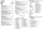
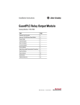
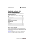
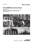
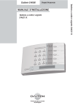
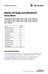
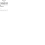
Installation Instructions
Kinetix 6200 and Kinetix 6500
Control Modules
Catalog Numbers
2094-SE02F-M00-S0, 2094-SE02F-M00-S1, 2094-EN02D-M01-S0, 2094-EN02D-M01-S1
Topic
Page
About the Control Modules
1
Catalog Number Explanation
2
Before You Begin
2
Install the Control Modules
4
Connector Data
6
Motor Overload Protection
11
Additional Resources
12
About the Control Modules
Each integrated axis (IAM) power module and axis (AM) power module requires one control
module. Each control module provides user I/O, safety, auxiliary feedback, and motor feedback
connections. Kinetix® 6200 control modules use sercos interface to communicate with the
Logix5000™ controller and EtherNet/IP to access the safety configuration tool. Kinetix 6500
control modules use EtherNet/IP for programming the Logix5000 controller and safety
configuration tool. In addition, the Kinetix 6200 and Kinetix 6500 control modules are available
with either safe torque-off or safe speed monitoring functionality.
Refer to Additional Resources on page 12 for user documentation supporting installation and
wiring, integration with ControlLogix®, CompactLogix™, or SoftLogix™ controller platforms,
troubleshooting, and safety functions.
2 Kinetix 6200 and Kinetix 6500 Control Modules
Catalog Number Explanation
This publication applies to the Kinetix 6200 and Kinetix 6500 control modules.
Kinetix 6200 Sercos Control Modules
Cat. No.
Description
2094-SE02F-M00-S1
Kinetix 6200 control module, sercos fiber optic, safe speed monitoring
2094-SE02F-M00-S0
Kinetix 6200 control module, sercos fiber optic, safe torque-off
Kinetix 6500 EtherNet/IP Control Modules
Cat. No.
Description
2094-EN02D-M01-S1
Kinetix 6500 control module, EtherNet/IP, safe speed monitoring
2094-EN02D-M01-S0
Kinetix 6500 control module, EtherNet/IP, safe torque-off
Before You Begin
Remove all packing material, wedges, and braces from within and around the components. After
unpacking, check the item nameplate catalog number against the purchase order.
Each 2094-SE02F-M00-S0 and 2094-EN02D-M01-S0 safe torque-off control module ships
with one motion-allowed plug for the IOD connector. Install the 44-pin motion-allowed plug
on the IOD connector when the safe torque-off functionality is not used and no other I/O
connections are required for your application.
TIP
Connector kits for user I/O, safety, and auxiliary feedback (catalog numbers 2090-K6CK-D44M
or 2090-K6CK-D44S0) and motor feedback (catalog number 2090-K6CK-D15M), are not
provided. Refer to the Kinetix Motion Accessories Technical Data, publication GMC-TD004, for
more information.
This procedure assumes you have prepared your panel, mounted your Bulletin 2094 power rail,
and Bulletin 2094 power modules. For installation instructions regarding equipment and
accessories not included here, refer to the instructions that came with those products.
ATTENTION: Plan the installation of your system so that you can perform all cutting, drilling,
tapping, and welding with the system removed from the enclosure. Because the system is of the
open type construction, be careful to keep any metal debris from falling into it. Metal debris or
other foreign matter can become lodged in the circuitry and result in damage to components.
Rockwell Automation Publication 2094-IN012C-EN-P - August 2013
Kinetix 6200 and Kinetix 6500 Control Modules 3
Module Compatibility
Kinetix 6000 IAM/AM modules and Bulletin 2094 power modules with Kinetix 6200 control
modules are completely compatible and can be used together on the same Bulletin 2094 power
rail.
IMPORTANT
Kinetix 6200 (sercos) and Kinetix 6500 (EtherNet/IP) control modules are not compatible and
cannot be used on the same Bulletin 2094 power rail.
Drive/Control Module Compatibility
IAM Module/
Control Module
IAM Power Module
2094-xCxx-Mxx-S
Kinetix 6000 (sercos)
N/A
2094-xMxx-S
Kinetix 6000
AM Module
2094-BMxx-M
AM Power Modules
Kinetix 6200
Control Module
Kinetix 6500
Control Module
Fully compatible
Fully compatible
Not compatible
Not compatible
Not compatible
Fully compatible
2094-SE02F-M00-Sx
Kinetix 6200 (sercos)
2094-BCxx-Mxx-M
2094-EN02D-M01-Sx
Kinetix 6500 (EtherNet/IP)
Rockwell Automation Publication 2094-IN012C-EN-P - August 2013
4 Kinetix 6200 and Kinetix 6500 Control Modules
Install the Control Modules
The IAM and AM power modules are equipped with two mounting hooks and a threaded hole.
The Bulletin 2094 control modules have two mounting studs, guide pins, and a captive screw for
mating the control module with a power module.
IMPORTANT
For convenience and ease of use, mount the IAM and AM power modules on the power rail
before mounting the control modules.
When the IAM power modules are placed on a flat surface, with the power-rail connectors
facing down, the mounting screw that extends from the front of the drive and fastens to the
power rail, pushes back and interferes with the control module installation.
Refer to the Kinetix 6200 and Kinetix 6500 IAM and AM Power Modules Installation
Instructions, publication 2094-IN011, for more information.
Follow these steps to mount Bulletin 2094 control modules to IAM (inverter) power module or
AM power modules. In this procedure an IAM power module is shown.
1. Remove all input power from the IAM power module.
Verify that the Power-applied indicator is off. When the indicator is on, voltage is
present on the IAM and AM power module signal connectors.
ATTENTION: To avoid damage to equipment, do not mount your Bulletin 2094 control
module to the power module when the Power-applied indicator is on. Remove all
input power from the IAM power module before mounting the control module.
2. Position the control module in front of the power module.
Guide Pins
IAM or AM Power Module
(IAM power module is shown)
Captive
Screw
Threaded Hole
in Tongue
Signal Connectors
Power-applied Indicator
Mounting Hooks
Bulletin 2094 Control Module
(Kinetix 6200 control
module is shown)
Mounting Studs
(other mounting stud is hidden from view)
Rockwell Automation Publication 2094-IN012C-EN-P - August 2013
Kinetix 6200 and Kinetix 6500 Control Modules 5
3. Align the control module mounting studs so they engage with the power module hooks.
Mounting Stud
(right side)
IAM or AM Power Module
(IAM power module is shown)
Mounting Hook
(right side)
Left-side mounting stud and hook are
hidden from view.
Bulletin 2094 Control Module
(Kinetix 6200 control
module is shown)
4. Pivot the control module toward the power module to engage the signal connectors and
guide pins.
IAM or AM Power Module
(IAM power module is shown)
Guide Pins
Straddling Tongue
Guide Pin Alignment on
Either Side of Tongue
Bulletin 2094 Control Module
(Kinetix 6200 control
module is shown)
Mounting Stud and
Hook Engaged
(right side)
Left-side mounting stud and hook are
hidden from view.
5. Tighten the captive screw.
Captive Screw
(apply 1.1 N•m (10 lb•in) torque)
IAM or AM Power Module
(IAM power module is shown)
Bulletin 2094 Control Module
(Kinetix 6200 control
module is shown)
6. Repeat step 2 through step 5 to mount a control module onto each power module
installed on your Bulletin 2094 power rail.
Rockwell Automation Publication 2094-IN012C-EN-P - August 2013
6 Kinetix 6200 and Kinetix 6500 Control Modules
Connector Data
Use these illustrations to identify the control module connectors and indicators.
Kinetix 6200 Control Module Features and Indicators (sercos)
Control Module (2094-SE02F-M00-Sx) Top View
1
2
3
Item
Description
4
5
1
Guide pins (2x)
2
2
Captive screw
3
Sercos communication rate and
optical power switches
4
Sercos Transmit (Tx) connector
5
Sercos Receive (Rx) connector
6
Control Module (2094-SE02F-M00-Sx) Front View
7
8
10
11
12
13
14
9
Item
Description
6
Four-character status display
7
PORT 1 status Indicator
8
Drive status indicator
9
Comm status indicator
10
DC bus status indicator
11
Safety lock status indicator
(only 2094-SE02F-M00-S1 modules)
12
I/O, safety, and aux feedback (IOD) connector
13
Power module mounting screw access hole
14
Motor feedback (MF) connector
15
Control Module (2094-SE02F-M00-Sx) Bottom View
Item
Description
15
Ethernet (PORT1) connector
Rockwell Automation Publication 2094-IN012C-EN-P - August 2013
Kinetix 6200 and Kinetix 6500 Control Modules 7
Kinetix 6500 Control Module Connectors and Indicators (Ethernet)
1
2
Control Module (2094-EN02D-M01-Sx) Top View
Item
Description
1
Guide pins (2x)
2
Captive screw
Control Module (2094-EN02D-M01-Sx) Front View
2
3
4
5
6
7
Item
Description
3
Four-character status display
4
PORT 1 status indicator
5
PORT 2 status indicator
6
Module status indicator
8
7
Network status indicator
9
8
DC bus status indicator
9
Safety lock status indicator
(only 2094-EN02D-M01-S1 modules)
10
I/O, safety, and aux feedback (IOD) connector
10
11
12
11
Power module mounting screw access hole
12
Motor feedback (MF) connector
Control Module (2094-EN02D-M01-Sx) Bottom View
13
14
Item
Description
13
Ethernet (PORT1) connector
14
Ethernet (PORT2) connector
Kinetix 6200 and Kinetix 6500 Control Module Connectors
Designator
Description
Connector
IOD
User I/O (drive), safety, and auxiliary feedback
44-pin high-density D-shell
MF
Motor feedback
15-pin high-density D-shell
Tx and Rx
Sercos connections for controller programming
(only Kinetix 6200 modules)
Sercos fiber-optic (2x)
PORT1
Ethernet connection for safety configuration
PORT2
Ethernet connection for controller programming
(only Kinetix 6500 modules)
RJ45
Rockwell Automation Publication 2094-IN012C-EN-P - August 2013
8 Kinetix 6200 and Kinetix 6500 Control Modules
ATTENTION: To avoid damage to the sercos Rx and Tx connectors, use only finger-tight torque
when attaching the fiber-optic cables to the Kinetix 6200 control modules. Do not use a wrench
or any other mechanical assistance.
For more information, refer to Fiber-optic Cable Installation and Handling Instructions,
publication 2090-IN010.
IOD Connector Pinouts
This is the IOD connector pinout for safe speed monitoring (-S1) control modules.
Catalog Numbers 2094-SE02F-M00-S1 and 2094-EN02D-M01-S1
IOD (1)
Pin
Signal
IOD Pin
Signal
0
–
12
–
IOD (1)
Pin
Signal
23 (S52)
SLS_IN_CH0
IOD (1)
Pin
Signal
33 (X32)
LM_IN_CH0
34 (X42)
LM_IN_CH1
1
AUX_SIN+
AUX_A+
13
–
2
AUX_SINAUX_A-
14
24VPWR (2)
24 (S62)
SLS_IN_CH1
35 (51)
DC_OUT_CH0
3
AUX_COS+
AUX_B+
15
24VCOM (2)
25
RESET_REF
36 (52)
DC_OUT_CH1
4
AUX_COSAUX_B-
16
–
26 (S34)
RESET_IN
37 (S72)
ESM_IN_CH0
5
AUX_DATA+
AUX_I+
17 (A1)
SPWR
27 (S11)
TEST_OUT_0
38 (S82)
ESM_IN_CH1
6
AUX_DATAAUX_I-
18 (A2)
SCOM
28 (S21)
TEST_OUT_1
39
24VPWR (3)
7
AUX_CLK+
19 (S12)
SS_IN_CH0
29 (68)
SLS_OUT_CH0
40
24VCOM (3)
8
AUX_CLK-
20 (S22)
SS_IN_CH1
30 (78)
SLS_OUT_CH1
41
INPUT1
9
EPWR_5V
21 (34)
SS_OUT_CH0
31 (S32)
DM_IN_CH0
10
ECOM
11
EPWR_9V
22 (44)
(1)
(2)
(3)
SS_OUT_CH1
32 (S42)
42
INPUT2
43
INPUT3
44
INPUT4
DM_IN_CH1
Designators in parenthesis refer to the Guardmaster® MSR57P safety relay and PowerFlex® 750-Series safety option terminals.
Signals 24VPWR and 24VCOM (IOD-14 and IOD-15) apply to only the 2094-SE02F-M00-S0 or 1094-EN02D-M01-S0 (safe torque-off) control
modules.
Signals 24VPWR and 24VCOM (IOD-39 and IOD-40) are a 24V DC source you can use to operate the digital inputs (50 mA maximum per input).
Refer to the Kinetix 6200 and Kinetix 6500 Safe Speed Monitoring Safety Reference Manual,
publication 2094-RM001, for signal descriptions and more information on safe-speed
monitoring safety functions.
Rockwell Automation Publication 2094-IN012C-EN-P - August 2013
Kinetix 6200 and Kinetix 6500 Control Modules 9
This is the IOD connector pinout for the safe torque off (-S0) control modules.
2094-SE02F-M00-S0 and 2094-EN02D-M01-S0 Control Modules
IOD
Pin
Signal
IOD
Pin
Signal
0
–
12
–
IOD
Pin
Signal
23
SS_IN_CH2
IOD
Pin
Signal
33
–
34
–
1
AUX_SIN+
AUX_A+
13
–
2
AUX_SINAUX_A-
14
24VPWR
24
SS_IN_CH3
35
–
3
AUX_COS+
AUX_B+
15
24VCOM
25
RESET_REF
36
–
4
AUX_COSAUX_B-
16
–
26
RESET_IN
37
–
5
AUX_DATA+
AUX_I+
17
SPWR
27
TEST_OUT_0
38
–
6
AUX_DATAAUX_I-
18
SCOM
28
TEST_OUT_1
39
24VPWR (1)
7
AUX_CLK+
19
SS_IN_CH0
29
–
40
24VCOM (1)
8
AUX_CLK-
20
SS_IN_CH1
30
–
41
INPUT1
9
EPWR_5V
21
SS_OUT_CH0
31
10
ECOM
11
EPWR_9V
22
(1)
SS_OUT_CH1
–
42
INPUT2
–
43
INPUT3
–
44
INPUT4
32
Signals 24VPWR and 24VCOM (IOD-39 and IOD-40) are a 24V DC source you can use to operate the digital inputs (50 mA maximum per input).
Refer to the Kinetix 6200 and Kinetix 6500 Safe Torque-off Safety Reference Manual,
publication 2094-RM002, for signal descriptions and more information on safe torque-off safety
functions.
IOD Connector Pin Orientation
Pin 30
Pin 44
Pin 15
Pin 31
Pin 1
44-pin Control Module
I/O, Safety, and Auxiliary
Feedback (IOD) Connector
Pin 16
Rockwell Automation Publication 2094-IN012C-EN-P - August 2013
10 Kinetix 6200 and Kinetix 6500 Control Modules
Feedback Connector Pinouts
MF Pin
Description
Signal
1
Sine differential input +
A differential input +
MTR_SIN+
MTR_A+
2
Sine differential input A differential input -
MTR_SINMTR_A-
3
Cosine differential input +
B differential input +
MTR_COS+
MTR_B+
4
Cosine differential input B differential input -
MTR_COSMTR_B-
5
Data differential input/output +
Index differential input +
MTR_DATA+
MTR_I+
6
Encoder common
MTR_ECOM
7
Encoder 9V power output
MTR_EPWR9V
8
Hall commutation S3 input
MTR_S3
9
Clock output +
MTR_CLK+
10
Data differential input/output Index differential input -
MTR_DATAMTR_I-
11
Motor thermostat
(normally closed) (1)
MTR_TS+
12
Hall commutation S1 input
MTR_S1
13
Hall commutation S2 input
MTR_S2
14
Encoder 5V power output
MTR_EPWR5V
15
Clock output -
MTR_CLK-
(1)
Not applicable unless motor has integrated thermal protection.
IMPORTANT
Drive-to-motor power cables must not exceed 90 m (295.5 ft). Additional limitations apply.
Refer to the Kinetix 6200 and Kinetix 6500 Modular Servo Drive User Manual, publication
2094-UM002, for more information.
MF Connector Pin Orientation
Pin 15
Pin 11
Pin 6
Pin 10
Pin 5 15-pin Control Module
Pin 1 Motor Feedback (MF) Connector
Rockwell Automation Publication 2094-IN012C-EN-P - August 2013
Kinetix 6200 and Kinetix 6500 Control Modules 11
Motor Overload Protection
This servo drive uses solid-state motor overload protection that operates in accordance with
UL 508C. Motor overload protection is provided by algorithms (thermal memory) that predict
actual motor temperature based on operating conditions as long as control power is continuously
applied. However, when control power is removed, thermal memory is not retained.
In addition to thermal memory protection, this drive provides an input for an external
temperature sensor/thermistor device, embedded in the motor, to support the UL requirement
for motor overload protection.
Some motors supported by this drive do not contain temperature sensors/thermistors; therefore,
motor overload protection against excessive consecutive motor overloads with power cycling is
not supported.
This servo drive meets the following UL 508C requirements for solid-state overload protection.
Motor Overload Protection Trip Point
Value
Ultimately
100% overload
Within 8 minutes
200% overload
Within 20 seconds
600% overload
ATTENTION: To avoid damage to your motor due to overheating caused by excessive,
successive motor overload trips, follow the wiring diagram provided in the user manual for
your motor and drive combination.
Refer to your servo drive user manual for the interconnect diagram that illustrates the wiring
between your motor and drive.
Rockwell Automation Publication 2094-IN012C-EN-P - August 2013
Additional Resources
These documents contain additional information concerning related products from
Rockwell Automation.
Resource
Description
Kinetix 6200 and Kinetix 6500 Modular Multi-axis Servo Drive
User Manual, publication 2094-UM002
Provides information on installing, configuring, startup,
troubleshooting, and applications for your Kinetix 6200 and
Kinetix 6500 servo drive systems.
Kinetix 6000M Integrated Drive-Motor System User Manual,
publication 2094-UM003
Provides information on installing, configuring, startup,
troubleshooting, and applications for your Kinetix 6000M
integrated drive-motor (IDM) system.
Kinetix 6000 Power Rail Installation Instructions,
publication 2094-IN003
Provides information on the installation of your Bulletin 2094
Power Rail.
Fiber-optic Cable Installation and Handling Instructions,
publication 2090-IN010
Provides information on proper handling, installing, testing,
and troubleshooting fiber-optic cables.
System Design for Control of Electrical Noise Reference Manual,
publication GMC-RM001
Provides information, examples, and techniques designed to
minimize system failures caused by electrical noise.
EMC Noise Management DVD, publication GMC-SP001
Kinetix 6200 and Kinetix 6500 Safe Speed Monitoring Safety
Reference Manual, publication 2094-RM001
Kinetix 6200 and Kinetix 6500 Safe Torque-off Safety Reference
Manual, publication 2094-RM002
Provides information on wiring, configuring, and
troubleshooting the safety functions of your Kinetix 6200 and
Kinetix 6500 drives.
Kinetix Motion Control Selection Guide, publication GMC-SG001
Specifications, motor/servo-drive system combinations, and
accessories for Kinetix motion control products.
Kinetix Servo Drives Specifications, publication GMC-TD003
Provides product specifications for Kinetix Integrated Motion
over EtherNet/IP, Integrated Motion over sercos interface,
EtherNet/IP networking, and component servo drive families.
Rockwell Automation Product Certification, website
http://rockwellautomation.com/products/certification
For declarations of conformity (DoC) currently available from
Rockwell Automation.
Rockwell Automation Industrial Automation Glossary,
publication AG-7.1
A glossary of industrial automation terms and abbreviations.
You can view or download publications at http://literature.rockwellautomation.com. To order
paper copies of technical documentation, contact your local Allen-Bradley distributor or
Rockwell Automation sales representative.
Allen-Bradley, CompactLogix, ControlLogix, Guardmaster, Kinetix, Logix5000, PowerFlex, Rockwell Software, Rockwell Automation, and
SoftLogix are trademarks of Rockwell Automation, Inc.
Trademarks not belonging to Rockwell Automation are property of their respective companies.
Rockwell Otomasyon Ticaret A.Ş., Kar Plaza İş Merkezi E Blok Kat:6 34752 İçerenköy, İstanbul, Tel: +90 (216) 5698400
Publication 2094-IN012C-EN-P - August 2013
Supersedes Publication 2094-IN012B-EN-P - October 2009
PN-215234
Copyright © 2013 Rockwell Automation, Inc. All rights reserved. Printed in the U.S.A.