1
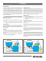
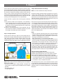
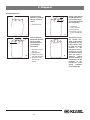
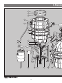
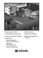
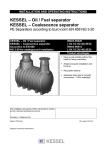
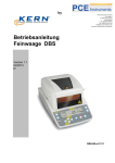
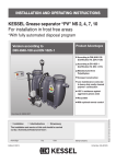
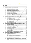
INSTALLATION, OPERATING AND MAINTENANCE INSTRUTIONS KESSEL Grease separator ‘SE’ M NS 2, NS 4, NS 7, NS 10, 15 and 20 with manual waste disposal device KESSEL-Grease Separator „SE“ M NS 2, 4, 7, 10, 15 and 20 according to DIN 4040 and DIN EN 1825-1 Product Advantages Compact / Light weight for easy shipping and handling Frequent disposal of freshly collected grease and sludge into connected storage tanks even during separator operation Separate disposal / collection of grease and sludge The installation and service of this unit should be carried out by a licensed professional servicer Name / Signature Edition 2012/07 Date Place Company Stamp Subject to technical amendment Smooth wax-like surface prevents the building up to coagulated oils and grease. ID-Nr. 010-076 1. Safety Instructions Follow all local and national accident prevention regulations! An electrical heating cable is located inside the heating cover! It is FORBIDDEN to damage the heating cover by drilling, sawing, grinding it or subjecting it to any other process which takes away metal or by driving screws into it. Disconnect the separator from its power source before carrying out maintenance work. During operation, maintenance or repair of the system, all DIN- / VDE- / DVGW norms and guidelines as well as any other appropriate local and national safety regulations must be followed! The system is only designed to handle wastewater from a kitchen with a maximum temperature of 60 deg Celsius. Higher temperatures can result in damage to the system. The motor protection relay on the rinsing motor and the internal temperature controller of the mixing motor automatically reactivate after turning off once the motor has cooled. The grease / water mixture in the plant may become very hot. Please use appropriate care during all work on the system. CAUTION – risk of slipping During disposal, cleaning or maintenance, grease or water may spill on the floor of the operating area causing a very slippery surface. No part of the plant should be stepped on. The plant is not to be climbed on as a means of reaching other installations. Use separate ladders etc. for this purpose. Because of the possible formation of bio gasses, SMOKING IS PROHIBITED while the separator is open or the collection barrels are being exchanged. Only operate the heater in the heating cover (filled with water or grease) when ventilated. A pocket of air in the upper portion of the heating dome could cause the heating dome to overheat due to the air pocket not allowing the heating cables to cool properly. No access for UNAUTHORISED PERSONS No storing of foods (for reasons of hygiene) The operating area must be selected so that there is sufficient access around and above the separator plant for disposal, cleaning and maintenance work. Wastewater inside the separator can contain bacteria. All body parts (hands, fingers, etc.) which come in contact with the separator should be properly washed and disinfected after the work is completed. Clothing coming in contact with the separator or wastewater should also be changed and washed accordingly. When leaving the plant, always check the following: The discharge valves to the grease and sludge barrels must be closed The rinsing-line valve must be open. The cover to the sludge trap must be tightly closed The storage barrel lids must be screwed on tight. Safety procedures / instructions concerning the separator must be familiar to all persons operating the separator! 2 Table of contents Safety instructions ........................................................................................................Page 2 2.1 2.2 2.3 2.4 Installation instructions ....................................................Page Assembly .........................................................................Page Control unit mounting .......................................................Page Installation example .........................................................Page 7 8 8 8 4.1 4.2 4.3 4.4 Control unit settings .........................................................Page Operation ..........................................................................Page Functions / Steps of the disposal procedure ....................Page Setting parameters ..........................................................Page ........................................................................................................Page 1. General 2. Installation 3.1 3.2 3.3 3.4 3.5 3. Commissioning 4. Operation 5. Disposal Placing separator into operating mode ............................Page Instructions and hand-over ..............................................Page Hand-over protocol ..........................................................Page Filling ................................................................................Page Ventilation .........................................................................Page Disposal steps .................................................................Page 4 9 9 9 9 9 10 10 10 10 11 ..........................................................................................Page 14 6. Explosion diagram ..........................................................................................Page 16 7. Control unit ..........................................................................................Page 19 8. Malfunctions and remedial measures ..........................................................................................Page 21 9. Accessories and replacement parts 10. Maintenance and servicing checks 11. Maintenance instructions for SE separators 12. Warranty ..........................................................................................Page 22 ..........................................................................................Page 22 ..........................................................................................Page 23 13. Declaration of Conformity ..........................................................................................Page 24 15. Hand-over certificate ..........................................................................................Page 26 14. Manufacturer / Separator data and information .........................................................................................Page 25 Dear customer, We are pleased that you have chosen a KESSEL product. The entire system was subjected to a stringent quality control before leaving the factory. Nevertheless, please check immediately whether the system has been delivered to you complete and undamaged. In case of any transport damage, please contact the shipping company. Before the KESSEL ‘SE’ separator is installed and placed into operation, it is mandatory and in your own interest to completely read through and follow all the information contained in this Installation, Operation and Maintenance Manual. KESSEL AG 3 1. General 1.1. Application Oils and greases in wastewater are not allowed to be drained into public wastewater pipes / sewers and also not into to lakes / rivers. Oil and greases in wastewater pipes can collect on the interior walls causing a reduction in the cross sectional area of the pipe and eventually pipe blockage. In addition, over time the collected grease begins to decompose and turn acidic which can lead to odour nuisances as well as the corrosion / degradation of the drainage pipes and system. Without grease separators, the oils / greases will collect on the surface of ponds / lakes as well as wastewater treatment collection ponds causing reduction of oxygen access to these waters. DIN 1986 Part 1 requires that harmful substances are retained. For this reason, grease separators in accordance with DIN 4040 must be provided and the grease disposed of appropriately. 1.2. System Description Separator function The special feature of the Type „SE“ grease separator for self disposal of waste is its method of disposal. While conventional separators must be emptied completely and shut down while this work is carried out, in the case of the „SE“, only the ma- terial which has been separated out needs to be disposed and is drained off via discharge pipes into exchangeable barrels. The grease separator can be emptied any time without having to interrupt the process. The separated material is in smaller quantities and is in a fresh state due to the fact that the sludge and grease is emptied multiple times per week. Barrels which have been filled are replaced with empty ones. Displaced air from the separation system is fed back into the separator meaning that no problematic odours are released during operation / disposal. If the grease solidifies, it can be returned to a liquid state via the separator’s heated cover. During the heating process self cleaning takes place – as the grease liquefies any particles / solids settles out of the grease layer and settle to the base of the tank. Sediments which settle out in the separator tank are pumped back to the sludge trap via a circulation system. Inlet Outlet Recycling Disposal/ Sludge storage tank Grease storage tank 4 1. General DIN 4040 The KESSEL grease separators for the self disposal of waste „SE“ are designed in accordance with DIN 4040. The sludge trap and grease separator are housed in different tanks. The volumes, size of calming zones and shape of the installed units to some extent exceed the specifications laid down in the norm / standard. No external energy requirements means that „SE“ grease separator plants operate without requiring an energy supply during grease separation. Reduced drinking water consumption and lower energy costs and wastewater fees, resulting from improved water quality and possible re-utilisation of fresh grease, are the economical and ecological objectives. In accordance with the effluent disposal regulations, the operator can put a higher priority on re-utilisation than disposal. moved via the grease discharge pipe. The heavier material settles out to the base of the sludge trap and is later drained into the collection and transport barrels. Disposal of the material in closed barrels is achieved with almost no smell. When changing the barrels, there may be a temporary release of odours. Materials Series „SE“ KESSEL grease separator plants consist of a separate sludge trap and grease separator. The tanks, their integrated units and pipe work are all made from PE-HD. The smooth, wax-like surface of polyethylene hinders the build-up of deposits and solids and is therefore easy to clean. The plants are fitted with odour-proof covers made from Duroplast 2K. The fittings and units are resistant against corrosive / aggressive wastewaters and are designed for use in damp areas. No bad odours In the grease separator, the light substances, such as fats, oils and floating sludge, accumulate on the surface and can be reDimensioned drawing and information table Illustration shows an NS 2 separator Inlet Outlet Sludge trap Grease separation area Cover with quick release clamp Heating dome Sludge storage barrel Grease storage barrel Ventilation Cleaning access Control unit Grease mixing motor / lever Rinsing pump 2 4 7 10 NS H L b B h1 h2 h3 1850 2000 1020 1400 1450 1570 650 1850 2200 1300 1700 1450 1570 730 Waste Contents Sludge trap Grease trap Weight – empty 410 l 410 l see illustration 15 20 5 570 l 1060 l 200 kg 260 kg 1200 kg 1750 kg Weight – full h2 h3 h2 h1 h1 h3 2. Installation l b1 b b1 b l Illustration shows NS 2 and NS 15 Inlet Outlet Sludge trap Grease separation area Cover with quick release clamp Heating dome Sludge storage barrel Ø NS DN NS 2 NS 4 NS 7 NS 10 100 100 150 150 110 110 160 160 NS DN NS 15 NS 20 NS 25 200 200 200 Ø 200 200 200 Dimensions l x b 1760 1830 2230 2230 930 930 1300 1300 Dimensions l x b 3600 4100 4600 1200 1300 1400 Grease storage barrel Ventilation Cleaning access Control unit Grease mixing motor / lever Rinsing pump b1 h1 h2 h3 Separator in Liter Weight in kg Art. Nr. 1330 1330 1700 1700 1230 1630 1630 1730 1300 1700 1700 1800 1700 2100 2200 2300 600 l 950 l 1450 l 1600 l 97 128 186 192 93202.00/SE1-CNS 93204.00/SE1-CNS 93207.00/SE1-CNS 93210.00/SE1-CNS Weight in kg Art. Nr. 485 505 535 93215.00/SE1-CNS 93220.00/SE1-CNS 93225.00/SE1-CNS b1 h1 h2 h3 Separator in Liter 1650 1750 1850 1730 1730 1730 1800 1800 1800 2300 2300 2300 2950 l 3650 l 4350 l 6 2. Installation 2.1. Installation instructions The grease separation plant is supplied complete in pre-assembled units. Under normal circumstances, the equipment is set up by a plumber or can, if requested, be installed by a KESSEL technician for an agreed upon fee. When installing the plant, the following must be observed 1. The safety instructions on Page 4 must be followed. 2. The instructions on the packaging must be taken into account! No non approved parts of the separator should be used to move or lift the separator during transport or installation. 3. The grease separation plant must be checked for transport damage immediately on arrival. 4. The technical data relating to your plant will be found on the serial plate on one of the tanks and the electrical data will be found on the serial plate attached to the control unit. All data are recorded in these instructions as well the plant pass. Documents relating to the equipment are included at the back of the instructions. 5. Bad odours will be released if the plant or barrels are not handled properly or maintenance work is not carried out in the proper manner. For this reason, we recommend installing the grease separator in a separate room with suitable ventilation (such as a fan). It is also advisable to install the grease separator in a tiled room with at least one floor drain and a hot water supply in order to ease maintenance and cleaning work. The height of the room must be sufficient for work to be carried out at the maintenance ports (minimum 30 cm from the ceiling). The width of the room should allow for a working space of about 1 m on all sides. 6. In the case of rooms with restricted access, the tanks can be dismantled and reassembled (see exploded diagram on Page 14). 7. Be sure that the maximum allowable floor loading in the room of installation is not exceeded (see weight table). 8. The plant must be installed on a level surface in a frost free area. 9. In order for the separator to function properly the temperature in the room of installation should not be below 15 degrees Celsius. 10. The service side is pre-assembled at the factory in accordance with the order. This can be altered on site. (See assembly instructions). Assemble the plant components using the connection elements supplied with the equipment. (Screw the tanks together using a maximum torque of 7 Nm). 11. The inlet and outlet of the separator feed and discharge pipe must be connected on-site. Do this in accordance with the standards DIN 1986. 12. The fall / drainage pipes to the inlet of the separator should have at least a 1 meter long horizontal run with a slope of at least 1:50 before entering the separator. The transition from the fall pipe to the calming stretch must be constructed from two 45 degree bends. This reduces ➜ the risk of the siphon and siphon trap being sucked empty. ➜ the amount of air admitted to the system, air movements and build-up of bad odours ➜ the formation of foam in the separator. If the separator plant is installed below the local backwater level, a wastewater lifting station must be installed in accordance with DIN 1986, providing local regulations do not require otherwise. Lifting units must also be provided with their own ventilation pipe. Important on-site requirements for proper function and odour free grease separator operation: ➜ Grease separator plants and their feed and discharge pipes must be provided with sufficient ventilation in accordance with DIN EN 1825-2. Consequently, as a ventilation pipe, the feed must be taken above the roof. All pipes connected to the plant that are more than 5 m long must be ventilated separately. If the main wastewater pipe to the separator is longer than 10 m and not separately ventilated – then this pipe must also be ventilated. ➜ In order to avoid the build up of bad odours, the feed and discharge pipe connections must be firmly connected and all seals must be fitted carefully. ➜ All drainage fixtures connected to the grease separator should be equipped with odor traps and sludge traps. Large items such as utensils, ketchup / mustard wrappers and bones etc will cause the separator, pumps and valves to malfunction. 2.2 Assembly 1. Grease and sludge separator components Set up the grease separator tank (10a) and the sludge separator tank (11a) Connect the drainage hoses (10b and 11b) to the sludge disposal port (4a) and to the grease disposal port (6a) Connect the ventilation hoses (10c and 11c) to the connection port on the sludge and grease storage barrel covers 7 2. Installation 2.2.1 Anschließen Connect the inlet and the outlet of the grease separator to the on-site drainage pipes as well as connecting the main drainage pipe to a ventilation pipe. 2.2.2 Checks 2.3 Control unit mounting The main power switch must be placed in the 0 position in order to open the control unit. Use the included mounting template in order to drill four holes in the wall – the included dowels and screws should be used for mounting the control unit to the wall. The control unit should be mounted in a frost free area and not in direct sunlight. It should also be placed All pipe, hose and storage barrel connections must be checked to assure that they are watertight. The manual disposal valves must be placed in the base position meaning: - Sludge and grease disposal valves in the closed position (4a, 6a) - Rinsing valve between grease and sludge separation areas in the open position in a position so that the cover can be completely opened to allow full access into the control unit. 2.4 Installation example Grease separator ventilation Inlet Ventilation pipes should be connected directly to outdoor ambient air (roof). The ventilation pipes should not be connected to one another. Public sewer Wastewater from the grease separator which is collected below the public sewer level should be pumped with a twin pump lifting station. The pressure disposal pipe should be plumbed above the local backwater level and then drained with gravity into the public sewer (this prevents any backwater from disturbing the operation of the lifting station). 8 KESSEL SE M NS 2 grease separator Sludge trap Sludge storage barrel Grease storage barrel Sampling chamber KESSEL basement drain ‘The Universal’ with integrated twin backwater flaps KESSEL Aqualift S Duo lifting station Product Accessories Sourced on-site 3. Commissioning 3.1 Placing separator into operation mode Before allowing wastewater from the kitchen to enter the separator make sure the following is done: - Interior of separator as well as the inlet and outlet are completely cleaned and free of any debris Completely fill the separator with cold mains drinking water – until water flows out of the outlet. Check the entire separator and all pipe / hose connections to assure they are watertight. Also assure that the separator was not damaged during shipping or installation. Check all pipes for watertightness by conducting a: - Visual inspection - Pressure test 3.3 Hand over protocol (see attachment) 3.4 Filling All valves should be in the operational position – meaning closed – only the sludge transfer valve (1c) should remain open. Fill the entire separator with clean cold water until water flows out of the outlet. This can be done by running a faucet from a sink which is connected to the grease separator. 3.5 Ventilation The hood / dome of the separator must be ventilated! 3.2 Instructions and hand-over The commissioning and initial grease separator training is normally handled by a KESSEL customer service representative. 1. The following persons should be present during the grease separator commissioning - Plumber - Representative of the building owner Also recommended to be present - Person who will be responsible for the operation of the separator - Grease separator disposal company 2. Preparation for the hand over and initial training - All sanitary connections must be complete - Completely filling the separator with cold mains drinking water - The disposal company must be arranged to be present during the first disposal 3. Instructions - Information concerning the disposal - Practical training of the separator operation - Function check of the separator - Instructions on how often the grease separator should be disposed 4. Hand-over of the installation and operational manual 5. After the initial training has been completed, the separator should be returned to normal operational mode – meaning the separator must be filled with clean cold mains drinking water 9 closed 4. Operation activated (internally set automated procedures will not start!) 4.1 Control unit settings 4.1.1 General The following functions are controlled by the control unit: - Rinsing (Euro Norm grease separators do not have the rinsing function.) - Heating - Mixing These functions are automatically started and ended according to the programmed settings. The system’s components can also be operated manually by using the control unit (See Menu 2.1) 4.1.2 Programming the functions The time of day, date and disposal program has been factory set. 4.2 Operation The control unit has a ‘Start’ and ‘Stop’ button (5) for manually controlling the disposal and a button for acknowledging any alarms (3). The current operating status of the separator is displayed by an LED (1), an alarm / malfunction LED (2) and a function LED (4). The control unit can be operated by using the ‘Up▲’, ‘Down▼’, ‘ESC’ and ‘OK’ buttons (7). Please follow the operating manual (8). Before conducting any work on the control unit be sure to disconnect it from its power source (9) (see safety instructions). ➀ ➁ ➂ ➃ ➄ ➈ ➇ ➆➅ Operation – LED Alarm-LED Alarm – button Pump operation – LED START/STOP Digital Display Navigation buttons ‘Up/down’ + ‘ESC/OK’ Operating instructions Disconnect control unit from power 4.3 Functions / Steps of the disposal procedure 0 System info 1 Information 2 Maintenance 3 Settings 2.1 Manual operation 2.2 Automated operation 2.3 SDS (Self Diagnosis System) 2.4 Service dates 2.5 Activating the Remote Control Note: For proper disposal of collected grease, the heating function should be run for at least 2 hours before disposal. During the last minute of heating, the mixing motor should also run. If the automated heating times are changed, the mixing times should be changed accordingly. 4.4 Setting parameters Note: When programming the heating / mixing times be sure that no times run into the next day. For example if heating begins at 22:00 it should end at 23:59. Setting the heating times In Menu Section 3.1.1 the day on which heating should occur can be set. Also here the starting time of the heating and the duration of the heating can be set. 3. Settings 3.1 Parameters 3.1.1 Heating 3.1.1.1 Every day 3.1.1.2 Monday 3.1.1. ........... Setting the mixing function 3.1.1.8 Sunday Note: When programming the heating / mixing times be sure that no times run into the next day. For example if heating begins at 22:00 it should end at 23:59. 3. Settings 3.1 Parameters 3.1.2 Mixing 3. Settings 3.1 Parameters 3.1.3 Rinsing 3.1.2 Duration Setting the rinsing function In Menu 3.1.3 on the control unit the day of the week that rinsing should take place can be set. Here you can also set the time of day that the rinsing should begin and also the duration of the rinsing. The control unit is set up for automated or manual operation. Manual operation has the priority over automated operation. If manual operation is activated, the automated operation is de- 3.1.3.1 Every day 3.1.3.2 Monday 3.1.3.3 .......... 3.1.3.8 Sunday 10 5. Disposal Disposal Steps The aim of re-utilising grease requires frequent waste disposal from the grease separator in order to keep the biochemical decomposition process to a minimum. The discharge of separated material must therefore be carried out not only according to quantity but also according to time - at least twice per week. The volume of the grease separator in the case of NS 2 is 80 litres and in the case of NS 4, it is 160 litres in accordance with the Standard. The collection barrel holds approx. 60 litres. Failure-free and proper operation of the plant is only guaranteed if the waste from the plant is disposed of in time. ➤ For the flow chart of the separation operation, see Section 2. ➤ A brief set of instructions in which the most important functions are explained are attached to the control unit. Step 1: Rinsing During the rinsing process, the sediments are transferred from the grease separator into the sludge trap and grease films and floating sludges are conveyed from the sludge trap into the grease separator. Warning: The sludge trap must be filled to the overflow level. The rinsing process must not be started immediately after sludge discharge otherwise the grease-separation area will be pumped out! Too frequent or too slow sludge transfer can cause the grease separator area to be pumped out Manual rinsing ➤ The valve on the rinsing line (1c, page 14)) must be open (standard position) ➤ Start the pump in the manual mode (Control Unit Menu Section 2.1) Step 2: Grease disposal Disposal should take place at the end of the programmed heating times. Heating times can be customer set (see time settings in Section 4.4) in order to better match the operation to on-site requirements At the end of the set heating time (set at 2 hours at the factory), slowly open the grease discharge valve (6a, page 14). Observe the flow of grease through the transparent filling hose (10b, page 14). Drain the grease and any floating sludge into the grease storage barrel until either the barrel (F) is full (which can be detected when no more grease is capable of flowing into the barrel) or until grease is no longer visible in the transparent hose (10b, page 14). Now close the grease disposal valve (6a, page 14). E C S Automatic rinsing Automatic rinsing is triggered via a time switch. For this reason, leave the valve on the rinsing line (1c) open during normal operation of the grease separator. In order to check that the pump is operating properly, rinsing should be carried out briefly by hand once per month during waste disposal. Whether the pump is delivering or not can be established by the noise of liquid running into the sludge trap. E C B G F A 11 S B G A F 5. Disposal In the case that no grease flows out into the collection barrel, the heating duration must be extended, until the hardened grease turns liquid. Depending on the room temperature and the amount of grease this heating could me more than two hours. On the control unit display the heating mode is displayed. The internal temperature sensor regulates the heating until the programmed heating time has elapsed. The start and stop of the heating dome occurs automatically. In the case that no grease drains into the grease collection barrel: a) The amount of water in the separator is not sufficient to create enough pressure to push out the grease. In this case a drainage fixture connected to the grease separator (kitchen sink for example) should be run to allow more water into the separator b) If there is still hardened grease in the separator. The disposal intervals should be shortened (draining of grease and sludge should take place more frequently) Step 3: Sludge disposal Slowly open the valve (4a, page 14) of the sludge trap (C). Observe the sludge draining through the transparent hose (11b, page 14) into the sludge collection barrel. Close the sludge drainage valve as soon as the amount of draining sludge decreases noticeably or if the sludge barrel is full (S). E C S B G P A F Note: Make sure to check the following when the disposal process has ended: - All valves are in the basic setting (closed) – except for the rinsing valve (1c, page 14) which should remain in the open position. - The heating (B) is off - The pump (P) is off Step 4: Collection barrel exchange Note: close valves and follow all safety instructions! Prepare an empty collection barrel and remove its cover. Disconnect the drainage pipe and ventilation pipe from the collection barrel and unclip the quick release clamp. Slowly remove the cover from the full tank (any remaining fluid in the drainage will have enough room in the collection tank) and place onto the empty barrel and connect. Place the closed cover onto the full collection barrel and secure properly. Mark the barrel to identify the contents (‘Grease’ or ‘Sludge’). We recommend changing the barrels at a later to date to allow them to cool and settle – preferably when the next disposal takes place. During this time the grease can settle to the top of the collection barrel and any water can settle to the bottom. This will aide in the reduction of odours when exchanging barrels. Note: - In the case that the collection barrels are so full that sludge or grease backs up into the transparent hoses then it is important to change the barrel´s immediately to prevent any blockage from building up in the hoses. - Store all full barrels in a cool and frost free area. - Collection barrels which are full should be taken off site as soon as possible. If stored too long, and depending on the temperature of the storage room, the contents of the barrels can begin to decompose causing gas build up which can result in gases / odours escaping from the barrels. - In the case that a disposal company handles the removal of the barrels, make sure that any replacement barrels supplied to you by the disposal company are the same size as the original barrels and have an original KESSEL cover. Tips on reducing odour build up 1. When exchanging barrels to it cleanly and quickly. 2. Make sure that the barrels covers are properly secured. 3. Any spilled wastewater should be quickly cleaned up. 4. Any filled or partially filled storage barrels (depending on room temperature) should be removed from site at a maximum within 4 weeks. It is recommended that the barrels are stored in a very cool (frost free) area. The decomposition process in the collection barrels results in gas build up inside the barrels which can cause them to bulge and release bad smelling odours. By continuous odour problems please see Section ‘Malfunctions and Remedial Measures’. 12 5. Disposal Collection barrel with twist (screwed) storage / transport covers Exchanging barrels Sludge collection barrel with operational cover (with transparent hose and ventilation connection) � Screwed cover I III Grease collection barrel with operational cover (with transparent hose and ventilation connection) � Ventilation connection port � Drainage inlet � Center of cover for inlet and ventilation � Threaded cover (for twist tightening) 13 II IV � Ventilation connection port � Drainage inlet � Center of cover for inlet and ventilation Operational covers are custom designed so that when completely full still have enough room to allow the entire contents of the transparent drainage hose to fit into the collection barrel when the cover is removed (which prevents spilling or overflowing of the contents of the transparent hose during collection barrel exchange). 6. Explosio 2f 2e 2d 3c 11d 2c 2b 2a 6a 9d 9c 3a 11c 4b 11b 4a 9b 11a 1a 9a 14 1b 1c 3b 5a on diagram ill. shows NS 2 Lower frame 1b Pump rinsing system 1c Rinsing system valve 1a Base section of sludge trap 2b Tank seal / gasket 2c Upper section of sludge trap 2d Cover seal 2e Sludge trap cover 2f Quick release clasp 2a 8 Rinsing line hose 3b Rinsing line stub 3c Exchange stub 3a 6b 4a 4b 7 Sludge discharge valve Sludge discharge cover Lower section of grease separator 5b Tank seal / gasket 5c Heating dome 5a 6c 6d Grease discharge valve 6b Mixer 6c Grease discharge cover 6d Cover seal / gasket 6a 7 5c 8 5b 10c 10b Compensation tank Ventilation pipe Control unit 9b Pump cables 9c Heating dome cables 9d Mixer cables 9a 10a Grease collection barrel 10b Filling hose 10a 10c Ventilation hose 11a Sludge collection barrel 11b Filling hose 11c Ventilation hose 11d Exchange stub 15 7. Control unit Control unit picture / Control unit ID sticker description The control unit ID sticker is located on the right narrow side of the control unit ill. 1 Control unit ID sticker description Control unit type Control unit article number Connection voltage and frequency Current range Protection class (IP) Control unit serial number Control unit replacement part number Danger symbol Protection category CE symbol Disposal information – do not dispose of control unit in household trash Control unit hardware id Outputs Potential free contact Optional: Remote speaker alarm (Artikel-Nr. 20162) • changeover contact, center contact, closing contact, open Contact • max. 42 VAC / 0,5 A • Connection contacts for remote speaker alarm ill. 2 16 7. Control unit Heizhaube Heating mantle Anschlußbelegung an Pos.11 Wiring at Pos. 11 Erdung / Grounding Temperaturfühler Temperature probe Temperatursicherung Thermal fuse Heizwicklung Heating coil ↔ ↔ ↔ Temperaturfühler Temperature probe 1000 ± 10 Ω bei 25° Temperatursicherung Thermal fuse ≤ 0,4 Ω Heizwicklung Heating coil 40 ± 5Ω bei 25° Erdung / Grounding 17 7. Control unit Electrical information: No heating rod Single heating rod 230V single phase, 50 Hz Connection jacks Mains switch on control unit Twin heating rods IP 54 C 16 A FI 30 mA IP 54 C 16 A FI 30 mA IP 54 C 16 Amp FI 30 mA Power supply 230V single phase, 50 Hz Connection Connection jacks Power supply disconnection Mains switch on control unit Connection values Protection class Fusing On-site RCD 400V 3 - phase, 50 Hz Connection jacks Mains switch on control unit Max. 5130 Watt when connecMax. 2430 Watt when connec- Max. 3630 Watt when ting: ting: connecting: Heating dome: 230 V single Heating dome: 230 V single phase, 50 Hz, 1200 Watt Heating dome: 230 V single phase, 50 Hz, 1200 Watt Mixing motor: 230 V single phase, 50 Hz, 1200 Watt Mixing motor: 230 V single phase, 50 Hz 180 Watt phase, 50 Hz 180 Watt Rinsing motor: 230 V single Mixing motor: 230 V single Rinsing motor: 230 V single phase, 50 Hz 180 Watt phase, 50 HZ, max 750 Watt phase, 50 HZ, max 750 Watt Heating rods: 230 V single Heating rod: 230 V single Rinsing motor: 230 V single phase, 50 Hz, max 1500 Watt phase, 50 Hz, max 1500 Watt phase, 50 HZ, max 750 Watt 18 8. Malfunctions and remedial measures Follow the safety instructions before carrying out any work on the separator (see Page 2) The following checks and remedies must be carried out by a licensed professional servicer. If necessary please contact the company that commissioned the separator. Grease separator: Fault No or hardly any grease discharged Possible cause No heating or heating time too short Large quantity of grease stored Room temperature under to 15°C Gradual build-up of solid grease layer Build-up of layer of floating sludge layer Foreign material blocking the grease discharge valve Remedial action Switch- heating on again. Run heating mode longer If possible, raise the temperature of the room. Even if grease is fluid in a cold state – still use heating function Discharge floating sludge during each disposal. Pressure reduction in the heating dome Dismantle hose and valve and clean. Clear the discharge hoses, remove if necessary Foreign material / solids blocking the grease - Install solids filter in kitchen sinks or in main wastewater drain before separator discharge valve - Instruct kitchen to not allow solids into kitchen drainage fixtures - Clean grease disposal valve Air in the heating dome Not ventilated during commissioning Too little fluid in the sludge-trap tank Ventilate according to the instructions and heat if necessary. Ensure that the sludge-trap tank is filled to its upper edge with water Sludge separator: Fault Little or no sludge drains from separator Possible cause Sludge disposal blocked Connect included rinsing nozzle to the valve and rinse Disposal of sludge more frequently Solids blocking disposal valve Grease layer forming in sludge separation area Remedial action 19 Very little wastewater volume, high grease concentration 19 Completely empty sludge trap and clean - Install solids filter in kitchen sinks or in main wastewater drain before separator - Instruct kitchen to not allow solids into kitchen drainage fixtures Activate the rinsing pump more frequently 8. Malfunctions and remedial measures Pump: Fault Pump does not pump any fluid Possible cause Air in pump Remedial action Run the disposal pump – after approx 1 minute the pump begins moving fluid again Pump jammed or pump interior area blocked Disconnect control unit from its power source Remove motor’s cover and turn motor shaft If the motor is still jammed, close valve near pump, open the access to the pump’s impeller and clean impeller / pump area. Note that contents of the sludge disposal pipe will drain out. Rotation of pump wrong Pump’s internal thermal breaker activates (automatically shuts off pumps) Caution: only allow a licensed professional to handle this repair! Disconnect control unit from its power source. Change the electrical connection to allow for proper pump rotation. Pump is overloaded, or very high sludge content in pumping medium Caution: pump can activate at any time if pump cools! Possible cause Remedial action Ventilation pipe missing or ventilation pipe size too small Install ventilation pipe or increase size of existing ventilation pipe Permanent odor problems: Fault Odor problems Drainage pipes Storage barrels and connections Hoses Full storage barrels not removed in timely fashion (contents begin to decompose) Lifting station Room where separator is installed has closed walls and no or improper ventilation Check to ensure all drainage pipes and gaskets are properly connected and in proper operating condition Check barrels, barrel covers and pipe connections to barrels Check all hoses and hose connections Remove full storage barrels from room sooner Lifting station (which may be connected to outlet of grease separator) not properly ventilated Install ventilation / fresh air supply to room where separator is located. 20 9. Accessories and replacement parts Accessories can normally be installed to the system at a later date. Please contact KESSEL directly. Replacement parts Sampling chamber KESSEL offers sampling chambers for indoor free standing installation or for underground installation. All sampling chambers are completely odor tight. The sampling chamber allows wastewater samples to be taken from the separator’s effluent stream without allowing odors to escape. The wastewater samples can be used to analyze samples, for example in accordance with DIN 38409. Before taking a sample, the interior of the sampling chamber should be cleaned and rinsed. DIN 1986 Part 1 requires the installation of sampling chambers, please contact your local authorities for information if a sampling chamber is required for your installation. Aqualift F Lifting Station KESSEL offers various lifting stations which can be installed before or after the grease separator. Please note that a twin pump lifting station should be installed after a grease separator. Model Article Nr. Lateral outlet 915 871 Vertical outlet Pump power 1,1 kW 2,2 kW 915 870 Power connection 400 V DS (3-phase) 400 V DS (3-phase) NS Art. Nr. DN 100 28 659 DN 100 28 631 Description Art. Number Storage barrel cover (2e) 916 901 60 liter storage barrel (10a / 11a) 915 780 Gasket for barrel cover (2d) 917 201 Quick release clamp for barrel cover (2f) Chamber gasket for separator tank NS and Sludge trap NS 2 and NS 4 Chamber gasket for separator tank NS 4 See explosion diagram on page 14! 917 001 840 113 860 113 Article Best.Nr. General separator inspection from KESSEL Customer Service Grease separator log book 917 411 917 409 21 10. Maintenance and servicing checks Follow all safety instructions! 10.1 Maintenance The grease separator should be inspected every 6 months by a professional. Along with the disposal of the separator, the following work should also be completed: - The interior walls of the grease and sludge tanks should be inspected - The electrical systems and parts of the grease separator should be checked - All work completed on the separator should be entered in the log book All mechanical and electrical parts such as the pump, valves, closure valves, control unit etc. should be inspected every 6 months according the manufacturer’s instructions. - Interior walls of all components and any electrical systems should be checked - Assure that a proper ventilation pipe is connected near the separator’s inlet (this ventilation pipe should be connected to ambient air – to the roof) - Review the separator’s log book to make sure all log book entries seem plausible and accurate - Check to assure that all grease and sludge taken from the separator has been properly handled / disposed. - Assure that all required certifications and documents for the separator are available (drainage plan, authorizations, user’s manual) The results of the general inspection should be documented. Any irregularities, defects or problems with the separator should also be documented and repaired immediately. 10.2 General Inspection Before commissioning and then in regular intervals thereafter (but at a minimum every 5 years) the separator must be fully inspected by a licensed professional to assure all systems are in proper working order. Prior to this inspection the separator should be fully emptied and cleaned. Included in this general inspection is the following: - Required size of the grease separator should be checked to assure that the installed separator meets the requirements - Condition and watertightness of the separator should be checked 11. Maintenance instructions for SE separators Maintenance instructions for KESSEL ‚SE’ grease separators The person carrying out maintenance must be familiar with the operation of the plant. A spare gasket for the heating cover of the corresponding „SE“ plant should be taken to the site so that this can be changed if necessary. When opening the grease separator, bad odours must be expected. Preparation 1.) It must be ensured that no waste water runs into the grease separator during maintenance work (inform the operator). 2.) Dispose of grease and sludge in accordance with the operating instructions (abide by the heating times). Maintenance work on the sludge trap 1.) Open the cover to the sludge trap and remove all the water from inside (e.g. by having it pumped out by an effluent disposal company). 2.) Check the sludge discharge valve for obstructions, clean the inner discharge area and remove any possible blockages caused by larger objects. 3.) Wash down the inner walls of the sludge trap with warm clarified water, free them from any contamination and deposits and clean them. 4.) Check the feed to the sludge trap for obstructions and deposits and clean if necessary. 5.) Check the outlet of the rinsing line and clean if necessary. Maintenance work on the grease separator tank 1) Pump the water from the grease-separator tank to the sludge trap using the rinsing pump until the sludge trap is completely full. 2.) WARNING: Isolate the control box from the power supply before starting work. The electrical heating cover can now be removed. In order to do this, release the electrical plug connection(s), the transparent hose and the heating cover fasteners. Remove the heating cover. 3.) Have the residual water pumped out by, for example, an effluent-disposal company. 22 11. Maintenance instructions for SE separators 4.) Wash down the inside of the grease separator tank and the heating cover with warm clarified water and clean them, carefully removing any deposits that may be there. 5.) Flush through the transparent hoses with warm water and clean them. 6.) Clean the pipe connections between the sludge trap and the grease separator tank, rinse and clean the discharge valves, rinse pump and special covers for the disposal barrels and check for obstructions. 7.) Check the heating cover seal for any possible damage and exchange if necessary. Clean and grease the surface of the seals and reinstall the heating cover. 8.) Reassemble the plant. Additional comments If a sampling chamber has been installed, clean the interior and remove any debris. Carry out maintenance on the lifting station in accordance with the manufacturer’s installation instructions. Warm water is recommended when cleaning the lifting station. Re-commissioning the grease separator 1.) Check the whole separator system for leaks. 2.) Re-start the KESSEL „SE“ grease separator plant in accordance with Section 5.1. Maintenance work on the rinsing pump 1.) Shut off the rinsing system valve, release the electrical plug connection and place a flat container underneath to catch the water from the rinsing line. 2.) Slacken the screwed fasteners in the feet of the motor and remove the impeller pump. 3.) Clean the impeller and free the pump from any blockages that may be there. 4.) Reassemble the pump, open the valve and check that the pump is operating properly (check flow). 12. Warranty 1. In the case that a KESSEL product is defective, KESSEL has the option of repairing or replacing the product. If the product remains defective after the second attempt to repair or replace the product or it is economically unfeasible to repair or replace the product, the customer has the right to cancel the order / contract or reduce payment accordingly. KESSEL must be notified immediately in writing of defects in a product. In the case that the defect is not visible or difficult to detect, KESSEL must be notified immediately in writing of the defect as soon as it is discovered. If the product is repaired or replaced, the newly repaired or replaced product shall receive a new warranty identical to that which the original (defective) product was granted. The term defective product refers only to the product or part needing repair or replacement and not necessarily to the entire product or unit. KESSEL products are warranted for a period of 24 month. This warranty period begins on the day the product is shipped form KESSEL to its customer. The warranty only applies to newly manufactured products. Additional information can be found in section 377 of the HGB. 23 In addition to the standard warranty, KESSEL offers an additional 20 year warranty on the polymer bodies of class I / II fuel separators, grease separators, inspection chambers, wastewater treatment systems and rainwater storage tanks. This additional warranty applies to the watertightness, usability and structural soundness of the product. A requirement of this additional warranty is that the product is properly installed and operated in accordance with the valid installation and user's manual as well as the corresponding norms / regulations. 2. Wear and tear on a product will not be considered a defect. Problems with products resulting from improper installation, handling or maintenance will also not be considered a defect. Note: Only the manufacturer may open sealed components or screw connections. Otherwise, the warranty may become null and void 01.06.2010 EU-KONFORMITÄTSERKLÄRUNG EUEU KONFORMITÄTSERKLÄRUNG EC d declaration eclaration o off c conformity/ onformity/ D Déclaration éclaration C CE Ed de ec conformité onformité Nach Nach der der M Maschinenrichtlinie aschinenrichtlinie 2006/42/EG, 2006/42/EG, der der Niederspannungsrichtlinie N iederspannungsrichtlinie 2 2006/95/EG, 006/95/EG, R Richtlinie ichtlinie d der er elektromagnetischen elektromagnetischen V Verträglichkeit erträglichkeit 2 2004/108/EG 004/108/EG u und nd Bauproduktrichtlinie Bauproduktrichtlinie 89/106/EWG 89/106/EWG / According According to to th the e M Machine achine G Guidelines uidelines 2006/42/EG, 2006/42/EG, th the e L Low ow V Voltage oltage Guidelines Guidelin es 2006/95/EG, 2006/95/EG, E Electromagnetism lectromagnetism Guidelines Guidelines 2004/108/EG 2004/108/EG and and in in accordance ac c or danc e w with ith D Directive irective 8 89/106/EEC 9/106/EEC / Selon Selon les les directives directives mé mécaniques caniques 2006/42/EG, 2006/42/EG, lles es d directives irectives de de basse basse tension tension 2006/95/EG, 2006/95/EG, lles es d directives irectives p pour our lla a compatibilité compatibilité électromagnétique électromagnétique 2004/108/EG 2004/108/EG et et les les directives dir ectives d de e cconstruction ons truction 8 89/106/EWG 9/106/EW G Hiermit declare, nous déclarons, Hiermit erklären erklären wir, wir, / Herewith Herew ith we d eclar e, / Par o us d éc l ar ons , Par la la présente, pré sente, n est conforme à la norme EN 1825-1:2004 et p figurent sur la plaquette d´identification selon l M E. Thiemt L Vorstand Managing Board C R 24 25 Date Name of examiner This unit has been checked for watertightness to be sure that it is fully operational before leaving the factory. Description 2 Description 1 Density Volume Dimensions EN/Approval Ref.No./Material/Weight Mat.-No./Order-No./Prod. Date Mat.-Description Separator characteristics 15. Hand-over certificate Separator Type: __________________________________________________________ Day / Hour __________________________________________________________ Project description /Building services supervisor __________________________________________________________ Address __________________________________________________________ Builder __________________________________________________________ Telephone / Fax __________________________________________________________ Telephone / Fax Address __________________________________________________________ __________________________________________________________ Planner __________________________________________________________ Telephone / Fax __________________________________________________________ Address __________________________________________________________ Contracted plumbing company __________________________________________________________ Telephone / Fax __________________________________________________________ Address KESSEL-Commissions no.: __________________________________________________________ System operator /owner __________________________________________________________ Telephone / Fax __________________________________________________________ Address __________________________________________________________ User __________________________________________________________ Telephone / Fax __________________________________________________________ Address __________________________________________________________ Person of delivery __________________________________________________________ Other remarks __________________________________________________________ The system operator, and those responsible, were present during the commissioning of this system. ____________________________ Place and date ____________________________ Signature owner 26 ____________________________ Signature user 15. Hand-over certificate Handover certificate (copy for the company carrying out the installation) ❏ ❏ ❏ The initial operation and instruction was carried out in the presence of the person authorised to perform the acceptance and the system operator. The system operator/person authorised to perform the acceptance was informed about the obligation to service the product according to the enclosed operating instructions. Initial operation and instruction were not carried out. The client/ person responsible for initial operation was handed the following components and/or product components Initial operation and instruction is being carried out by (company, address, contact, phone) The exact coordination of the dates for initial operation/instruction is being carried out by the system operator and person responsible for initial operation. Place, date Signature of person authorised to perform acceptance 27 Signature of system operator Signature of the company carrying out the installation work K Backwater protection K Septic Systems K Drains and shower channels K Rainwater Management K Lifting Stations and pumps K Separators -Grease Separators -Oil-/ Fuel-/Coalescence Separators -Starch Separators -Sediment Separators K Inspection Chambers Systems