1
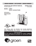
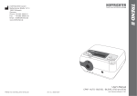
OPERATOR/SERVICE MANUAL
IMPORTANT INFORMATION, KEEP FOR OPERATOR
This manual provides information for:
MODELS
BPM-30/40G(CE) International
ECLIPSE™ ERGONOMIC
TILTING BRAISING PAN
· Stainless Steel
· Manual Tilt
· Gas Heated
THIS MANUAL MUST BE RETAINED FOR FUTURE REFERENCE.
READ, UNDERSTAND AND FOLLOW THE INSTRUCTIONS AND
WARNINGS CONTAINED IN THIS MANUAL.
FOR YOUR SAFETY
Do not store or use gasoline or other flammable vapors
and liquids in the vicinity of this or any other appliance.
POST IN A PROMINENT LOCATION
Instructions to be followed in the event user smells gas.
This information shall be obtained by consulting your
local gas supplier. As a minimum, turn off the gas and
call your gas company and your authorized service agent.
Evacuate all personnel from the area.
WARNING
Improper installation, adjustment, alteration, service or
maintenance can cause property damage, injury or death.
Read the installation, operating and maintenance instructions
thoroughly before installing or servicing this equipment.
NOTIFY CARRIER OF DAMAGE AT ONCE
It is the responsibility of the consignee to inspect the container upon receipt of
same and to determine the possibility of any damage, including concealed damage. Unified Brands suggests that if you are suspicious of damage to make a
notation on the delivery receipt. It will be the responsibility of the consignee to file
a claim with the carrier. We recommend that you do so at once.
Manufacture Service/Questions 888-994-7636.
Information contained in this document is known to be current and accurate at the time
of printing/creation. Unified Brands recommends referencing our product line websites,
unifiedbrands.net, for the most updated product information and specifications.
E (11/08)
PART NUMBER 160812, REV. C
(06/07)
1055 Mendell Davis Drive
Jackson, MS 39272
888-994-7636, fax 888-864-7636
groen.com
IMPORTANT — READ FIRST — IMPORTANT
THESE APPLIANCES MUST BE INSTALLED BY A COMPETENT PERSON IN CONFORMITY WITH THE
INSTALLATION AND SERVICING INSTRUCTIONS AND NATIONAL REGULATIONS IN FORCE AT THE TIME.
PARTICULAR ATTENTION MUST BE PAID TO THE FOLLOWING:
I. E. E. REGULATIONS FOR ELECTRICAL INSTALLATIONS
ELECTRICITY AT WORK REGULATIONS
GAS SAFETY (INSTALLATION & USE REGULATIONS
HEALTH AND SAFETY AT WORK ACT
FIRE PRECAUTIONS ACT
LOCAL AND NATIONAL BUILDING REGULATIONS
DETAILED RECOMMENDATIONS ARE CONTAINED IN INSTITUTE OF GAS ENGINEERS PUBLISHED
DOCUMENTS: IGE/UP/1, IGE/UP/2, BS6173 AND BS5440.
THESE APPLIANCES HAVE BEEN CE-MARKED ON THE BASIS OF COMPLIANCE WITH THE GAS
APPLIANCE DIRECTIVE, EMC AND LOW VOLTAGE DIRECTIVE FOR THE COUNTRIES, GAS TYPES AND
PRESSURES AS STATED ON THE DATA PLATE.
WARNING:
TO PREVENT SHOCKS, ALL APPLIANCES WHETHER GAS OR ELECTRIC, MUST BE
EARTHED.
ON COMPLETION OF THE INSTALLATION, THESE INSTRUCTIONS SHOULD BE LEFT WITH THE
ENGINEER-IN-CHARGE FOR REFERENCE DURING SERVICING. FURTHER TO THIS, THE USERS
INSTRUCTIONS SHOULD BE HANDED TO THE USERS AND THE INSTALLER SHOULD INSTRUCT THE
RESPONSIBLE PERSON(S) IN THE CORRECT OPERATION AND MAINTENANCE OF THE APPLIANCE.
EMPHASIS SHOULD BE MADE WITH REGARD TO SAFE OPERATION OF DRAIN VALVE.
IT IS MOST IMPORTANT THAT THESE INSTRUCTIONS BE CONSULTED BEFORE INSTALLING AND
COMMISSIONING THE APPLIANCE. FAILURE TO COMPLY WITH THE SPECIFIED PROCEDURES MAY
RESULT IN DAMAGE OR THE NEED FOR A SERVICE CALL.
CAUTION:
SHIPPING STRAPS ARE UNDER TENSION AND CAN SNAP BACK WHEN CUT.
CAUTION:
UNIT WEIGHS 420 TO 560 LB. (165 TO 255 KG). FOR SAFE HANDLING, INSTALLER
SHOULD OBTAIN HELP AS NEEDED, OR EMPLOY APPROPRIATE MATERIALS HANDLING
EQUIPMENT (SUCH AS A FORKLIFT, DOLLY, OR PALLET JACK) TO REMOVE THE UNIT
FROM THE SKID AND MOVE IT TO THE PLACE OF INSTALLATION.
WARNING:
INSTALLATION OF THE BRAISING PAN MUST BE DONE BY PERSONNEL QUALIFIED TO
WORK WITH GAS AND ELECTRICITY. IMPROPER INSTALLATION CAN RESULT IN INJURY
TO PERSONNEL AND/OR DAMAGE TO EQUIPMENT.
WARNING:
THIS UNIT IS DESIGNED FOR COMMERCIAL USE. NEVER USE HOME OR RESIDENTIAL
GRADE GAS CONNECTIONS. THEY DO NOT MEET GAS CODES AND COULD BE
HAZARDOUS.
DANGER:
ELECTRICALLY GROUND THE UNIT AT THE TERMINAL PROVIDED. FAILURE TO GROUND
UNIT COULD RESULT IN ELECTROCUTION AND DEATH.
WARNING:
KEEP THE APPLIANCE AREA FREE AND CLEAR OF COMBUSTIBLE MATERIALS.
CAUTION:
BE SURE ALL OPERATORS READ, UNDERSTAND AND FOLLOW THE OPERATING
INSTRUCTIONS, CAUTIONS AND SAFETY INSTRUCTIONS CONTAINED IN THIS MANUAL.
CAUTION:
KEEP FLOORS IN BRAISING PAN WORK AREA CLEAN AND DRY. IF SPILLS OCCUR,
CLEAN IMMEDIATELY TO AVOID THE DANGER OF SLIPS OR FALLS.
WARNING:
WHEN TILTING BRAISING PAN FOR PRODUCT TRANSFER:
1) USE CONTAINER DEEP ENOUGH TO CONTAIN AND MINIMIZE PRODUCT SPLASHING.
2) PLACE CONTAINER ON STABLE, FLAT SURFACE, AS CLOSE TO PAN AS POSSIBLE.
2
OM/SM-BPM-G
3) STAND TO SIDE OF PAN WHILE POURING — NOT DIRECTLY IN POUR PATH OF HOT
CONTENTS.
4) RETURN PAN BODY TO LEVEL POSITION AFTER CONTAINER IS FILLED OR
TRANSFER IS COMPLETE.
5) DO NOT OVER FILL CONTAINER. AVOID DIRECT SKIN CONTACT WITH HOT
CONTAINER AND ITS CONTENTS.
WARNING:
DO NOT HEAT AN EMPTY PAN FOR MORE THAN 5 MINUTES AT A SETTING HIGHER
THAN 300ºF (150ºC).
WARNING:
IF THE PAN CONTAINS ITEMS IN SAUCE OR MELTED FAT, THEY CAN SLIDE FORWARD
SUDDENLY DURING TILTING AND CAUSE THE HOT LIQUID TO SPLASH OUT.
WARNING:
AVOID ALL DIRECT CONTACT WITH HOT FOOD OR WATER IN THE PAN. DIRECT
CONTACT COULD RESULT IN SEVERE BURNS.
WARNING:
IT IS RECOMMENDED THAT WATER AND SOLUTIONS BE KEPT OUT OF CONTROLS AND
BURNERS. DO NOT USE HIGH PRESSURE SPRAY DIRECTLY ON THE CONTROL CONSOLE,
ELECTRICAL CONNECTIONS AND BURNERS. USE A GARDEN HOSE SPRAY CONNECTED
TO CITY WATER SUPPLY.
CAUTION:
MOST CLEANERS ARE HARMFUL TO THE SKIN, EYES, MUCOUS MEMBRANES AND
CLOTHING. PRECAUTIONS SHOULD BE TAKEN TO WEAR RUBBER GLOVES, GOGGLES
OR FACE SHIELD AND PROTECTIVE CLOTHING. CAREFULLY READ THE WARNINGS AND
FOLLOW THE DIRECTIONS ON THE LABEL OF THE CLEANER TO BE USED.
WARNING:
BEFORE REPLACING ANY PARTS, DISCONNECT THE UNIT FROM THE ELECTRIC POWER
SUPPLY AND CLOSE THE MAIN GAS COCK. ALLOW FIVE MINUTES FOR UNBURNED GAS
TO VENT. FAILURE TO DISCONNECT COULD RESULT IN ELECTROCUTION AND DEATH.
CAUTION:
USE OF ANY REPLACEMENT PARTS OTHER THAN THOSE SUPPLIED BY GROEN OR
AUTHORIZED DISTRIBUTORS CAN CAUSE INJURY TO THE OPERATOR AND DAMAGE TO
THE EQUIPMENT AND WILL VOID ALL WARRANTIES.
IMPORTANT: Service performed by other than factory authorized personnel will void all warranties.
OM/SM-BPM-G
3
Table of Contents
IMPORTANT OPERATOR WARNINGS (READ FIRST) . . . . . . . . . . . . . . . . . . . . . . . . . . . . . . . . . . . . . . . . . . . . . 2
REFERENCES . . . . . . . . . . . . . . . . . . . . . . . . . . . . . . . . . . . . . . . . . . . . . . . . . . . . . . . . . . . . . . . . . . . . . . . . . . . . . 4
EQUIPMENT DESCRIPTION . . . . . . . . . . . . . . . . . . . . . . . . . . . . . . . . . . . . . . . . . . . . . . . . . . . . . . . . . . . . . . . . . 5
1. INSTALLATION . . . . . . . . . . . . . . . . . . . . . . . . . . . . . . . . . . . . . . . . . . . . . . . . . . . . . . . . . . . . . . . . . . . . . . . . . 7
2. ASSEMBLY AND COMMISSIONING . . . . . . . . . . . . . . . . . . . . . . . . . . . . . . . . . . . . . . . . . . . . . . . . . . . . . . . .10
3. SERVICING AND CONVERSION . . . . . . . . . . . . . . . . . . . . . . . . . . . . . . . . . . . . . . . . . . . . . . . . . . . . . . . . . . 12
4. USER INSTRUCTIONS . . . . . . . . . . . . . . . . . . . . . . . . . . . . . . . . . . . . . . . . . . . . . . . . . . . . . . . . . . . . . . . . . . 17
5. CLEANING . . . . . . . . . . . . . . . . . . . . . . . . . . . . . . . . . . . . . . . . . . . . . . . . . . . . . . . . . . . . . . . . . . . . . . . . . . . 19
6. SAFETY PRECAUTIONS . . . . . . . . . . . . . . . . . . . . . . . . . . . . . . . . . . . . . . . . . . . . . . . . . . . . . . . . . . . . . . . . 20
7. MAINTENANCE . . . . . . . . . . . . . . . . . . . . . . . . . . . . . . . . . . . . . . . . . . . . . . . . . . . . . . . . . . . . . . . . . . . . . . . . 20
8. TROUBLESHOOTING . . . . . . . . . . . . . . . . . . . . . . . . . . . . . . . . . . . . . . . . . . . . . . . . . . . . . . . . . . . . . . . . . . . 21
9. PARTS LIST . . . . . . . . . . . . . . . . . . . . . . . . . . . . . . . . . . . . . . . . . . . . . . . . . . . . . . . . . . . . . . . . . . . . . . . . . . 23
10. SERVICE LOG . . . . . . . . . . . . . . . . . . . . . . . . . . . . . . . . . . . . . . . . . . . . . . . . . . . . . . . . . . . . . . . . . . . . . . . . 35
References
Canadian Standards Association
8501 East Pleasant Valley Rd.
Cleveland, Ohio 44131
Z83-11
Gas FoodService Equipment
Z223.1
National Fuel Gas Code
American National Standards Institute
1403 Broadway
New York, New York 10018
Canadian Gas Association
55 Scarsdale Road
Don Mills, Ontario M3B 2 R3
National Fire Protection Association
60 Battery March Park
Quincy, Massachusetts 02269
NFPA/54
NFPA/70
NFPA/96
Installation of Gas Appliances &
Gas Piping
The National Electrical Code
Ventilating Hoods
NSF
INTERNATIONAL
National
Sanitation Foundation
789 N. Dixboro Rd.
3475 Plymouth Road
P.O. Box 130140
Ann Arbor, Michigan 48106
Ann Arbor, Michigan 48113-0140
Underwriters Laboratories, Inc.
333 Pfingsten Road
Northbrook, Illinois 60062
4
OM/SM-BPM-G
Equipment Description
The following dimensions apply to CE model BPM braising pans:
Model
Width
Depth
Height
Weight (Kg)
BPM-30G
984 mm
1010 mm
1100 mm
190
BPM-40G
1226 mm
1010 mm
1100 mm
255
Groen™ Gas-Heated Eclipse™ Ergonomic Tilting
Braising Pans provide a stainless steel pan
equipped with patented heat transfer fins,
burner/combustion chamber, hand-operated or
electric powered tilting mechanism, thermostatic
controls, and hi nged cover. Eclipse serves as
braising pan, griddle, fry pan, oven, kettle, bainmarie and food warmer/server, can be adapted
for use as a non-pressure steamer
and can be
used to stir-fry, reheat and saute foods.
The pan body is made from heavy-duty stainless
steel welded into one solid piece, with a polished
interior and exterior. A pouring lip is welded to the
front wall. The cooking surface is a stainless steel
clad plate fitted with welded heat transfer fins
which assure uniform heat transfer over the entire
surface. The gas burner/combustion chamber
supplies the heat.
An easilyoperated worm and gear mechanism tilts
the pan and provides precise control for pouring or
dumping the contents of the pan. This hand-wheel
controlled mechanism is located in a stainless
steel console to the right of the pan body. To assist
cleaning, the pan bodycan be tilted past the
vertical position. When the pan is tilted, the
burners shut off automatically.
The braising pan is mounted on an open-leg frame
fabricated from tubular stainless steel. It has an
ignition system that uses electronic spark ignition.
Options available with these models are:
1. Fill faucet with swing spout. (Left or right mounted)
- specify single or double pantry
2. Fill faucet with 48" or 60" spray hose assembly
(left or right mounted) - specify single or double
pantry
3. Flanged Feet
4. Fold-down work tray (pan support) mounted on
right side.
5. 2” Tangent draw-off (Factory-installed must be
indicated on initial order)
6. Steamer Insert set.
7. Steamer Pan Carrier.
8. Pouring Lip Strainer.
9. Strainer for 2" TDO valve.
The thermostat provides automatic control of
cooking temperature. Operating the thermostat
dial on the front of the control console turns the
heat on or off and sets the pan temperature.
A vented, heavy gauge, one-piece, stainless steel
cover with a condensate drip shield on the rear
edge is standard on the Braising Pan. A fully
enclosed, torsion bar type counterbalance
provides easy operation to open the cover and to
maintain it open at any position. The cover opens
to the back and is hinged to the frame, so it moves
independently of the pan body.
Optional Tangent Draw-Off
OM/SM-BPM-G
5
Inspection & Unpacking
The unit will arrive completely assembled,
on a heavy skid, in a heavy cardboard carton.
Immediately upon receipt, inspect the carton
for damage. Report any apparent shipping
damage or an incorrect shipment to the
delivery agent.
Cut the straps holding the unit on the skid, and lift
the unit straight up off the skid.
CAUTION
SHIPPING STRAPS ARE UNDER TENSION
AND CAN SNAP BACK WHEN CUT.
When installation is to begin, get someone to
assist in removing the carton. Lift it straight up
and away from the unit. Do not simply raise it
and push backwards - it could damage the unit.
Write down the model number, serial number,
and installation date of your unit, and keep
this information for future reference. Space for
these entries is provided at the top of the
Service Log in this manual.
UNIT WEIGHS 420 TO 560 LB (190 TO 255
KG). FOR SAFE HANDLING, INSTALLER
SHOULD OBTAIN HELP AS NEEDED, OR
EMPLOY APPROPRIATE MATERIALS
HANDLING EQUIPMENT (SUCH AS A
FORKLIFT, DOLLY, OR PALLET JACK) TO
REMOVE THE UNIT FROM THE SKID AND
MOVE IT TO THE PLACE OF INSTALLATION.
Thermostat
Power
Switch
Cover
Indicator
Light
Manual Tilt
Handwheel
Flame Observation
Port
Stainless Steel
Console
The unit is strapped to a skid, and shipped in a heavy cardboard carton.
(Shown is model BPM-40G with optional right side mounted, double pantry faucet assembly.)
6
OM/SM-BPM-G
1. Installation
The following information pertains to the CE model BPM-G, and replaces or augments the information provided in
OM-BPM. These appliances must be installed by a competent person in conformity with the installation and
servicing instructions and national regulations in force at the time. Particular attention must be paid to the
following:
I. E. E. Regulations for Electrical Installations
Electricity at Work Regulations
Gas Safety (Installation & Use Regulations
Health and Safety at Work Act
Fire Precautions Act
Local and National Building Regulations
Detailed recommendations are contained in institute of gas engineers published documents: IGE/UP/1, IGE/UP/2,
BS6173 AND BS5440.
OM/SM-BPM-G
7
1.1 Installing Clearances
Minimum
Clearances
Left Side
Right Side
Rear
1.1.1
1.1.2
0mm
0mm
77mm
EQUIPMENT
Recommended
Clearances
17
600
Pastry Oven
17
600
Fryer
26
900
305-405mm (12-16”),
153mm (6”) when faucet is
installed on right side
Grill
17
600
Steak Grill
26
900
Boiling Pan
17
600
305mm (12") for service
Steamer
17
600
Vertical clearance of at least 1000 mm should be
allowed between the top edge of the flue outlet and
any overlying surface.
Sterilizing Sink
14
500
Bain-Marie
11
400
Adequate ventilation, whether natural or
mechanically induced, must be provided to ensure a
supply of fresh air for gas combustion, and to
facilitate effective removal of the products of
combustion.
Tea/Coffee Machine
8.5-14
300-500
1.1.4
For multiple installations, the requirements for
individual appliances should be added together.
Installation should be made in accordance with local
and national regulations applying at the time. A
competent installer must be employed.
1.1.7
ft³/min
Range, Unit Type
Ventilation recommendations for catering appliances
are provided in BS 5440 : 2. Furthermore, guidance
on the column of ventilation air required for different
types of catering equipment to ensure sufficient
room ventilation is provided at right.
1.1.6
m³/min
51mm (2”) for service,
153mm (6”) when faucet is
installed on left side
1.1.3
1.1.5
Ventilation Rate Required
The appliance governor is incorporated in the gas
control valve which is situated in the left control
cabinet. The control valve governor is suitable for
both natural and propane gases without conversion.
Installation pipework should be fitted in compliance
with IEGE/UP/2. The pipework should not be smaller
than the gas inlet connection (Rp½ [½” B.S.P.]).
An isolating cock must be located close to the
appliance to allow shut-down during emergencies or
service. Installation must be tested for gas
soundness and purged as specified in IGE/UP/1.
1.3 Electrical Supply
The appliance flue discharges horizontally from the
rear of the unit. It must not be directly connected to
any flue, mechanical extraction system, ducting, etc.,
which leads to the outside of the building. The
appliance is best discharged under an open canopy
connected with a ventilating system.
For a unit on casters, the installation shall be made with
a connector that complies with the standard for
Connectors for Moveable Gas Appliances, ANSI Z21.69
- CSA 6.16. Restrain movement of the unit by attaching
a cable or chain to the eyelet provided at the back of
the frame and anchor the cable or chain to the wall or
floor. Make the length and location of the cable such
that the unit cannot pull on the gas connection while
the cable is connected or quick-disconnect.
This unit is designed for connection to fixed wiring.
A suitably rated isolating switch with contact
separation of at least three millimeters on both poles,
must be fitted to the installation.
Power supply to this unit must be 230V, 1 Phase, 50/60hz
with wiring suitable for an electronic load of 50 watts.
The wiring must be executed in accordance with
the regulations listedinside the cover page of this
manual supplement.
Cable entry is at the control box on the rear right side
of the appliance. Access to the terminals is gained by
removing terminal block cover.
WARNING
THIS APPLIANCE MUST BE EARTHED.
The gas connection for a unit on casters must be made
with a quick-disconnect device that complies with
ANSI Z21.41 - CSA 6.9.
1.2 Gas Supply
Incoming service must be of sufficient size to supply
full rate without excessive pressure drop. A gas
meter is connected to the service pipe by the gas
supplier.
Any existing meter should be checked by the
supplier to ensure that the meter has the capacity for
passing the required rate of gas for the braising pan
in addition to any other gas equipment installed.
8
OM/SM-BPM-G
Fig. 1
Fig. 2
1.4 Water Supply
Not applicable to these appliances ezcept for
optional faucets..
1.5
Use of the appliance with non-approved gases in a
listed country, or use in other countries will void CE
certification.
1.6 Burner Adjustment
Gas System Performance
The tables below provide the total Gas Rates,
Injector Diameters and Pressure Adjustments for
model BPM-G (CE) using natural (G20) and
propane (G31) gas sources.
The burner primary airflow may be adjusted by
loosening the screw and sliding the aerator forward
or backward. (See photograph)
Total Gas Rate
Natural
Propane
Natural
Propane
Model
(G20)
(G31)
BTU/hr
BTU/hr
KW
KW
26.1
89,100
26.1
89,100
BPM-30G
36.1
123,300
36.1
123,300
BPM-40G
Injector Diameters-Natural & Propane Gas
Natural Propane No. of
Model Gas G20 Gas G31 Orifices
(mm)
(mm) (Injectors)
1.5
0.97
11
BPM-30G
1.5
0.97
15
BPM-40G
Gas Pressure Adjustment
A pressure test point is fitted on the burner manifold
and on the gas control valve.
NATURAL
GAS G20
PROPANE
GAS G31
Model
mbar
in. WC
mbar
in. WC
BPM-30G
8.0
3.2
19.4
7.8
Fig. 3
Gas is connected at the rear of the control
console.
BPM-40G
8.0
3.2
19.4
7.8
NOTE: With reference to the gas rate, pressure
adjustments and conversions, this appliance is
CE-approved for use with the following gases:
a) Gas Category I2H, G20 natural gas may be
supplied to the appliance in Austria, Denmark,
Finland, Greece, Iceland, Italy, Luxembourg,
Norway, Portugal, Spain, Sweden, Switzerland
and the United Kingdom.
Fig. 4
b) Gas Category I3P, G31 propane gas may be
supplied to the appliance in Germany, Ireland,
the Netherlands, Portugal, Spain, Switzerland
and the United Kingdom.
OM/SM-BPM-G
9
2. Assembly and Commissioning
2.1
Electrical Supply
Before commissioning the appliance, ensure that the
electrical installation has been performed in
compliance with relevant regulations. See
Paragraph 1.3, above.
WARNING
THIS APPLIANCE MUST BE EARTHED.
2.2
Pre-Commissioning Check
a) Remove literature and packing materials from
the interior and exterior of the unit.
b) Put enough water into the pan to cover the
bottom to a depth of 6-12mm. With the pan
body in the horizontal position, note how the
water lies in the pan, to confirm that the pan was
leveled properly during installation.
Fig. 6
Upper Control Box
f)
c) Verify that the rear heat shield panel is in place.
2.3
2.3.1
Operating the Braising Pan
Lighting Sequence
g) Repeat steps b through e.
a) Put water in the pan (6 to 12 mm deep)
h) To switch off the unit, put the toggle switch in the
Off position.
b) Check that gas and electricity mains are on.
c) Turn the toggle switch (Main Control Box) to the
“ON” position. The power neon (Main Control
Box) will illuminate.
Should the unit fail to light, turn the unit off and
wait for one or two minutes before attempting to
switch it on again. NOTE: Burner “ON” verification
can be confirmed by careful observation through
the Flame Observation Port. See Illustration on
page 6 of this manual for location of this port.
i)
2.3.2
Turn gas and electricity mains off.
Setting the Gas Pressure
d) Turn the thermostat (Upper Control Box) to the
desired setting.
e) Observe that the burners light by the lighting of
the heat neon (Main Control Box) (approximately
10-15 seconds).
Fig. 7
Connect a gauge to check pressure at the gas
manifold.
Fig. 5
Main (Lower) Control Box
a) During commissioning, a gas pressure check is
essential. Connect a suitable pressure gauge to
the gas manifold to perform this test. The
pressure gauge should be connected to the test
nipple (See photograph above).
b) Turn the gas and electricity mains on.
10
OM/SM-BPM-G
d) Set the thermostat knob at “10" and allow the oil
to heat up. Immerse a thermometer or
thermocouple 25 mm below the oil surface at the
center of the pan. Check that the temperature
stabilizes at 190ºC, (± 5ºC).
c) Light the burners as described in Paragraph
2.3.1, above.
d) Manifold gas pressure should be as noted in
Section 1.5 of the manual. If adjustment is
necessary, follow steps e through j, below.
e) Remove the screws which secure the ignition
module cover and remove the ignition module
cover panel. See Fig. 8.
Fig. 9
Adjust flow by turning the screw on the gas valve
governor.
Fig. 8
f)
Remove the governor cap screw on the gas
control valve to gain access to the screw inside
the turret. (See photograph at right)
CAUTION
THE TEMPERATURE MUST NOT EXCEED 200ºC
OR THE HIGH LIMIT THERMOSTAT WILL TRIP.
g) The governor is suitable for both natural and
propane gas.
h) Turn the screw inside the turret clockwise to
increase the pressure, anti-clockwise to reduce
it. Check the burner pressure again after 15
minutes operation, and adjust if necessary.
i)
Disconnect the pressure gauge from the test
point. Reseal the test point and test for gas
soundness.
j)
Replace governor cap screw, and replace
control box panel and lid.
e) If the unit fails to operate as described, the unit
should be serviced by an Engineer.
IMPORTANT
These appliances must be installed by a competent
person in conformity with the installation and
servicing instructions and national regulations in
force at the time. Particular attention must be paid
to the following:
I. E. E. Regulations for Electrical Installations
Electricity at Work Regulations
Gas Safety (Installation & Use Regulations
Health and Safety at Work Act
Fire Precautions Act
Local and National Building Regulations
Detailed recommendations are contained in institute
of gas engineers published documents: IGE/UP/1,
IGE/UP/2, BS6173 AND BS5440.
2.3.3 Checking Performance of Controls
a) Light the unit as described in Paragraph 2.3.1,
above. Check that the controls produce a healthy
spark from the electrode to the earthing post,
and that ignition is smooth and without delay.
b) Turn the thermostat off and then on. Check that
the burners go out when the thermostat is turned
off, and that they reignite smoothly when it is
switched back on. Repeat several times.
c) Fill the pan with unused oil up to the mark in the pan.
2.4
WARNING
DO NOT OVERFILL WITH OIL OR FIRE MAY
RESULT!
Instructions to Installer
IMPORTANT: After installing and commissioning
the appliance, the User’s Instructions should be
handed to the user or purchaser. Ensure that the
instructions for lighting, turning off, correct use
and cleaning are properly understood.
Emphasize the location of the main gas isolating
valve and demonstrate the emergency shut
down procedure.
OM/SM-BPM-G
11
3. Servicing and Conversion
3.1
Servicing
3.2
Notes:
3.1.1
Conversion
Notes:
IMPORTANT
BEFORE ATTEMPTING ANY SERVICING, ENSURE
THAT THE GAS ISOLATING COCK IS TURNED OFF
AND CANNOT BE INADVERTENTLY TURNED ON.
ENSURE ALSO THAT THE ELECTRICITY SUPPLY IS
DISCONNECTED.
AFTER ANY SERVICING OR EXCHANGE OF GAS
CARRYING COMPONENTS — ALWAYS CHECK
FOR GAS SOUNDNESS!
1. See Para 1.5, page 9 for important information. VERIFY
THE TYPE OF GAS TO BE USED. In the countries listed
in Paragraph 1.5, all conversions must be for approved gas.
2. All threaded gas connections must be sealed as specified
in paragraph 3.1, Note #2.
To change the type of gas used (e.g G20 to G31 or inverse)
following parts should be changed:
1. Burner injectors. See instruction 3.13 on page 16.
2. Igniter tube injector. This is inserted inside the igniter tube as
shown on below.
1. When replacing wiring connections refer to the wiring
diagram in the unit or this manual.
2. When any threaded gas connection is disturbed for any
reason, the threads must be resealed with appropriate
gas leak prevention sealant that is suitable for the type of
gas. Unified Brands/ Groen recommends gas sealant
compound such as Locktite® 243 or Unified Brands part
number 122002.
After Servicing
a) Test for gas soundness as specified in IGE/UP1
as appropriate after any gas connection has been
disturbed.
3. Gas valve spring. Install per instructions supplied with the
spring package as shown below.
b) If leaks are found, disconnect the mating parts, clean
the threads and apply recommended sealant as
specified in paragraph 3.1 Note 2 above.
c) Check for correct operation as appropriate (see
Installation, Section 1.5).
3.1.2
Regular Servicing Procedures
The following must be checked at regular intervals:
a) Burners
Clean the burners periodically to maintain
maximum performance. Burners are best
cleaned with a stiff bristle brush, or if necessary
with a wire brush. Take care not to damage the
burner.
4. Pilot orifice. Insert the black shaded orifice for G31 gas as
shown below. The light colored orifice is for G20 gas.
Clean the injector orifice with a wooden splinter or
toothpick. Avoid metal reamers, which may
distort or increase the orifice size.
WARNING - Do not leave any wood splinter or
bristles from brush in the burner or injector. Fire
could result.
b) Gears and Bearings
The gear housing has been fitted for proper
lubrication of moving parts. Since the gears do
not run in oil, periodic lubrication with grease is
essential. Frequency of lubrication depends on
operating conditions, but should occur at least
once every six months. Groen recommends the
use of a Number Two grade LGI lithium grease.
Add grease through the Zerk fittings on the gear
housing until grease flows out of the bearings
around the trunnion shaft. Place a liberal amount
of grease on the gear to cover the arc that is in
contact with the worm gear.
12
OM/SM-BPM-G
5. Data plate with correct rate and gas manifold
pressure information.
3.2.1
After Conversion
a) Test for gas soundness as specified in IGE/UP1
as appropriate after any gas connection has been
disturbed.
b) If leaks are found, disconnect the mating parts,
clean the threads and apply recommended sealant
as specified in paragraph 3.1 Note 2.
3.3
3.3.1
Removal of Control Panels
Removal of Electrical Panel Cover Assembly
a) Remove the three screws which secure the lid to
the control cabinet around its edge - 2 on sides,
1 on rear.
b) Lift-up the lid, being careful to dislodge the 2
pins welded at lower edge of front end.
Fig. 11
Fig. 10
c) Replace in reverse order
3.3.2
3.3.3
3.4
Removal of Control Cabinet Side Panel
a) Remove lid as described above.
b) Remove 2 screws on lower edge of cover.
c) Remove 4 screws at center of cover.
d) Lift off the removable side panel.
e) Replace in reverse order.
Removal of Upper Control Box Panels
a) Remove thermostat knob and timer knob.
b) Remove 4 screws from top.
c) Remove upper panel and gasket.
d) Replace in reverse order.
Fig. 11A
c) Remove screws holding the tilt switch.
d) Withdraw the tilt switch from control
compartment.
e) Replace in reverse order.
3.6
Removal of Gas Control Valve (Turn
gas and electricity mains off)
a) Remove ignition module cover
described in Paragraph 3.4.
Removal of Spark Ignition Module
(Turn gas and electricity mains off)
a) Remove 2 screws on ignition module cover
(see Fig. 8)
b) Disconnect electrical leads from gas control
valve, hi limit thermostat and ignition module
assembly.
b) Disconnect electrical leads from spark ignition
module.
c) Undo and remove gas pipe assembly between
two pipe unions.
c) Remove retaining screws securing spark
ignition module.
d) Remove the gas control valve from piping
assembly.
d) Withdraw spark ignition module from
control compartment.
e) Replace in reverse order.
e) Replace in reverse order.
3.7
3.5
Removal of Tilt Switch (Turn gas and
electricity mains off)
a) Remove electical panel cover and control
as described in Paragraph 3.3.1 & 3.3.2.
b) Disconnect electrical leads from tilt switch
(See Fig. 11).
Removal of On/Off Switch
(Turn gas and electricity mains off)
a) Remove electrical panel cover
described in Paragraph 3.3.1.
b) Disconnect electrical leads from On/Off switch.
OM/SM-BPM-G
13
c) Undo and remove the retaining collar which
secures the On/Off switch to the outer surface of
the control cabinet.
d) Withdraw the On/Off switch from control
compartment.
WARNING
DO NOT OVERFILL WITH OIL OR FIRE MAY
RESULT!
e) Replace in reverse order.
3.8
Removal of Neons (Turn gas and
electricity mains off)
a) Remove control panel lid and side panel as
described in Paragraph 3.3.1 and 3.3.2.
b) Remove the control knob and place a
screwdriver down the centre of the spindle.
c) Light the unit and allow the oil to heat.
b) Disconnect the neons’ flying leads.
c) Undo and remove the retaining collar which
secures the neon to the control cabinet.
d) Remove the gasket between control box and panel.
e) Withdraw the neon from the control compartment.
f)
3.9
e) Replace control knob.
Replace in reverse order.
Removal of Operating Thermostat
d) Adjust the thermostat by turning the screwdriver
clockwise to decrease, and anti-clockwise to
increase temperature. Ensure that the
temperature settles at 190ºC (±5ºC). (Note:
Thermostat may cycle seven or eight times
before oil temperature settles at 190ºC).
3.10
Removal of High Limit Thermostat
(Turn gas and electricity mains off)
(Turn gas and electricity mains off)
To Replace
a) Remove upper control box panels as
described in Paragraph 3.3.3.
This device is set to shut off the flow of gas to the
burners to prevent oil temperature from exceeding
230ºC. Manual intervention is required to reset the
control in the event of a lockout.
b) Remove thermostat from front panel.
c) Remove electrical leads from operating
thermostat.
d) Remove operating thermostat phial from the
underside of the pan, and remove retaining clips.
e) Remove the retaining clip which secures the
flexible conduit to the pan side.
f)
Pull thermostat phial through the flexible conduit
(or cut if scrap).
g) Replace in reverse order.
To Calibrate
If calibration is required, use the following
procedures:
a) Fill the pan with unused oil to the indicated mark.
Place a thermocouple 25 mm below the oil
surface in the middle of the pan.
14
OM/SM-BPM-G
Fig. 12
Connects to the braising pan by means
of flexible conduit. (Rear of Upper Control Box)
To Reset
Remove the upper control box rear panel as
described in 3.3.3. Push the reset button on
the body of the high limit thermostat.
f)
To Replace
a) Remove the spark ignition module as
described in 3.4(a).
g) To remove, see replacement procedures above.
NOTE: After this test, reconnect the regulating
thermostat wires.
b) Remove 2 screws holding the limit thermostat.
Calibration
The high limit thermostat is of the fixed type. Its
calibration point may not be adjusted.
c) Remove high limit thermostat.
d) Replace in reverse order following the same
procedures.
WARNING
IF THE HIGH LIMIT THERMOSTAT FAILS TO CUT
OFF AT 230ºC IMMEDIATELY TURN OFF THE
GAS SUPPLY. CONDUCT AN INVESTIGATION
TO DETERMINE THE FAULT, AND CORRECT IT
BEFORE USING THE APPLIANCE AGAIN.
To Check Operation
Operation of the high limit thermostat must be
checked regularly. Use the following procedure:
a) Remove the upper control box from panel as
described in Paragraph 3.3.
If the high limit thermostat switches, but not at the
specified temperatures, the thermostat requires
replacement. Rejected thermostats must be
logged and returned.
3.11
Removal of Burners (Turn gas and
electricity mains off)
a) Undo and remove the front two retaining nuts of
the burner guard.
b) Fill the pan with unused oil to the indicated mark.
Place a thermocouple or thermometer 25 mm
below the oil surface in the middle of the pan.
b) Undo the two retaining nuts at the side of the
burner guard. Do not fully remove. The burner
guard will swivel back to allow access to the
burners.
c) Undo and remove the retaining screws holding
the burners.
WARNING
DO NOT OVERFILL WITH OIL OR FIRE MAY
RESULT!
d) Remove burner.
e) Replace in reverse order.
c) Ensure that the electrical power is off before
continuing. Disconnect the leads from the
operating thermostat. Connect the leads together
using the terminal block. This effectively removes
the operating thermostat from the circuit. It may
also be bypassed with a jumper across the
thermostat terminals.
3.12
Removal of Ignition Electrode (Turn
gas and electricity mains off)
a) Disconnect electrical leads from ignition electrode.
This electrode is also the sensing electrode.
b) Remove ignition electrode from bracket.
d) Switch the unit back on and light the unit as
described in the lighting instructions. The
burners will light and heat up the pan.
c) Replace ignition electrode.
d) Replace electric leads.
DO NOT LEAVE THE APPLIANCE DURING THIS
TEST.
e) If the high limit thermostat is functioning correctly,
the gas supply will cut off as the temperature
reaches 205 to 225ºC. Once the high limit
thermostat has tripped, switch off the mains
electricity. Reconnect the operating thermostat
and replace all panels.
e) Check that the distance between the igniter and
burner is within specified tolerances. Ensure
that smooth, rapid ignition is achieved once the
new spark igniter is in place.
OM/SM-BPM-G
15
3.13
Removal of Burner Orifices
(Injectors) (Turn gas and electricity
3.14
Fuse Replacement
a) Remove the control cabinet cover as
described in Paragraph 3.3.1.
mains off)
a) Remove burners (Paragraph 3.11).
b) Remove fuse from fuse holder (See Fig. 13).
b) Remove orifices from burner manifold.
c) Replace fuse with an identical fuse.
c) Replace in reverse order.
d) Replace in reverse order.
3.15
Transformer Replacement (Fig. 13)
(Smae as 3.14)
3.16 Wiring Diagram, BPM-30G & BPM-40G Models
Fig. 13
16
OM/SM-BPM-G
4. User Instructions
4.1
a) Check that gas and electricity mains are on.
1. Do not leave the braising pan unattended
when heating.
b) Turn the toggle switch (Main Control Box) to the
“ON” position. The power neon (Main Control
Box) will illuminate.
2. For frying, the depth of oil in the pan must never
exceed the maximum oil level mark on the inner
pan wall.
Lighting and Operation
c) Turn the thermostat (Upper Control Box) to the
desired setting.
d) Observe that the burners light by the lighting of
the heat neon (Main Control Box) (approximately
10-15 seconds).
WARNING
DO NOT OVERFILL WITH OIL OR FIRE MAY
RESULT. DO NOT ADD WATER OR WET FOOD
INTO HOT OIL.
e) Should the unit fail to light, it will lock-out.
Turn the unit off and wait for one or two minutes
before attempting to switch it on again.
f)
4.2
Repeat steps b through e.
Users’ Thermostat
Provides automatic control of the braising pan
temperature at selected temperatures up to a
maximum of 190ºC.
To Shut Down Braising Pan
a) Turn thermostat dial to the Off position.
b) Switch the On/Off switch to the Off position.
c) For a prolonged shut down
— Follow steps a and b
— Turn the gas and electricity mains off
d) Turn the tilting handle clockwise to pour out the
water or contents.
4.3
4.4
Filling the Braising Pan
Using hot water and detergent, clean out the pan
thoroughly prior to operation.
The pan should not be overfilled, and an allowance
should always be made for expansion and foaming of
the food being cooked. The maximum fill level is
marked on the inner pan wall (See Fig. 14)
4.5
Sequence of Operation
The following “sequence of operation” is provided to
help the user understand how the unit functions.
a) Switching the On/Off switch to the On position to
start the appliance causes the power neon to
illuminate.
b) Turning the thermostat sends a signal to the
ignition module.
c) The ignition module opens the pilot control valve
which allows gas to go to the pilot burner. It
simultaneously starts a sparking sequence
at the pilot.
d) The spark ignites the main pilot burner. Once this
occurs, the sensing probe detects the flame.
This confirms that lighting has been successful.
e) After a short period of time the main control valve
opens to full flow and lights the burners.
f)
The sparking/ignition sequence shuts off, and the
“Heat” neon illuminates.
g) If, however, a pilot flame is not detected within
55 seconds, the ignition module goes into lockout mode.
h) To restart the ignition sequence the ON/OFF
switch must be set to OFF and then back to ON.
i)
Fig. 14
In addition to the gas lockout, other safety
features include:
OM/SM-BPM-G
17
— A high limit safety thermostat which cuts off
the gas supply should the operating
thermostat fail (i.e., should the temperature
exceed operating limits).
4.6
Turn the hand crank on the front of the cabinet
clockwise to tilt the pan body forward. The pan will
stay in position when you stop turning the handle.
To return it to the upright position, turn the crank
anti-clockwise.
— A tilt switch which automatically cuts off the
gas supply when the unit is tilted when in
operation.
j.
l)
Should the main control thermostat fail and cause
the hi-limit thermostat to trip, the unit will stop
heating. To reset the high limit control, depress the
red reset switch located on rear of unit under the
gas piping. (See. Fig. 15)
WARNING
HI LIMIT RESET SHOULD BE USED SPARINGLY
TO COMPLETE AN ONGOING COOKING
OPERATION. IT INDICATES THAT UNIT
NEEDS SERVICING. CALL YOUR AUTHORIZED
SERVICE AGENCY TO COMPLETE THE
REPAIRS AND DO NOT USE THE UNIT AFTER
COMPLETING ONGOING OPERATION.
CONTINUED USE COULD RESULT IN
DANGEROUS CONDITION SUCH AS FIRE.
Fig. 15
18
WARNING
DO NOT STAND IN FRONT OF THE PAN WHEN
TILTING IT. BE CAREFUL TO KEEP HOT
CONTENTS FROM SPILLING. KEEP PEOPLE
AWAY FROM POURING LIP AREA WHEN
EMPTYING THE PAN.
When the pan reaches a set temperature, the
thermostat switch opens. This halts the signal to
the gas control valve and causes the valve to
shut off the flow of gas.
k) When the pan cools below its set temperature,
the thermostat switch closes and starts another
heating cycle. This on-off cycling continues,
keeping the pan at the desired temperature.
OM/SM-BPM-G
To Empty the Pan
4.7
Power Failure
a) If power to the unit is lost, do not attempt to
operate the appliance until the electricity has
been restored.
b) When the power comes on again, follow the
steps in Paragraph 4.1, Lighting and Operation.
5. Cleaning
WARNING
KEEP WATER AND SOLUTIONS OUT OF CONTROLS AND BURNERS. NEVER USE A HIGH PRESSURE
SPRAY DIRECTLY ON THE CONTROL CONSOLE OR ANY ELECTRICAL CONNECTIONS.
1. Before any cleaning operation, shut off the burner
by turning the thermostat dial to "0". If water or
cleaning solution will be sprayed, unplug the unit from
the electric power source, or shut off the power at the
circuit breaker or fuse panel.
2. Clean all food-contact surfaces soon after use,
before the pan has cooled completely. If the unit is in
continuous use, thoroughly clean and sanitize both
interior and exterior at least once every 12 hours.
CAUTION
MOST CLEANERS ARE HARMFUL TO THE
SKIN, EYES, MUCOUS MEMBRANES AND
CLOTHING. PRECAUTIONS SHOULD BE
TAKEN TO WEAR RUBBER GLOVES,
GOGGLES OR FACE SHIELD AND
PROTECTIVE CLOTHING. CAREFULLY READ
THE WARNINGS AND FOLLOW THE
DIRECTIONS ON THE LABEL OF THE
CLEANER TO BE USED.
3. Scrape or rinse out large amounts of food
residues, then wash the inside of the pan body with a
mixture of hot water and soap or an appropriate
detergent, such as Mikro-Quat from ECOLAB. Follow
the detergent supplier's recommendations on strength
of the solution to use. Rinse the pan thoroughly with
hot water and drain completely.
Use a brush, cloth, sponge or other non-abrasive
tool for cleaning.
4. To remove materials stuck to the equipment, use
a brush, sponge, cloth, plastic or rubber scraper, or
plastic wool along with the detergent or soap solution.
To minimize the effort required in washing, let the
detergent solution sit in the pan and soak into the
residue, or heat the detergent solution briefly in the
pan. Do NOT use any abrasive materials or metal
implement that might scratch the surface, because
scratches make the pan hard to clean and provide
places for bacteria to grow. Do NOT use steel wool,
which mayleave particles imbedded in the pan surface
and cause eventual corrosion and pitting.
5. As part of the daily cleaning program, cl ean all
external and internal surfaces that may have been
soiled. Remember to check such parts as the
underside of the cover, control console, etc.
6. Controls and the control console may be cleaned
with a damp cloth or sprayed with a garden hose spray
connected to city water supply. Do not use a pressure
sprayer directly on the unit or electrical parts.
Don’t use metal implements or steel wool to
clean the braising pan.
OM/SM-BPM-G
19
NOTICE
NEVER LEAVE A CHLORINE SANITIZER IN
CONTACT WITH STAINLESS STEEL SURFACES
LONGER THAN 30 MINUTES. LONGER
CONTACT CAN CAUSE CORROSION.
WARNING
DO NOT SPRAY WATER DIRECTLY ON
BURNERS AND GAS COMBUSTION
CHAMBERS.
sanitizing products. Following the supplier's
instructions, apply the sanitizing agent after the unit
has been cleaned and drained. Rinse off the sanitizer
thoroughly.
7. The exterior surface of the unit may be polished
with a recognized stainless steel cleaner.
8. If the equipment needs to be sanitized, use a
sanitizing solution equivalent to one that supplies 100
parts per million available chlorine. Obtain advice on
the best sanitizing agent from your supplier of
9. If there is difficulty removing mineral deposits or a
film left by hard water or food residues, clean the pan
thoroughly and then use a deliming agent, such as
Groen De-limer/De-Scaler (P/N 140513), in
accordance with the manufacturer's directions. Rinse
and drain the unit before further use.
10. If especially difficult cleaning problems persist,
contact your cleaning product representative for
assistance.
6. Safety Precautions
A stop-cock will be fitted in the gas pipe supplying the appliance. The user must be familiar with its location and
operation, and able to turn it off in an emergency.
If there is a smell of gas, immediately turn off the gas, ventilate the area, and call the gas supplier.
NEVER USE NAKED FLAME TO SEARCH FOR GAS LEAKS.
7. Maintenance
Your Braising Pan is designed to require minimum
maintenance, but certain parts may need replacement
after prolonged use. After installation, no user
adjustment should be necessary. If a service need
arises, only authorized personnel should perform the
work.
WARNING
ELECTRIC POWER ALWAYS SHOULD BE
SHUT OFF BEFORE WORK IS DONE ON
INTERNAL COMPONENTS.
Service personnel should check the unit at least once
a year. This periodic maintenance should include
inspecting electrical wires and connections,
cleaning the inside of the control console, and possible
adjustment of the pilot light. (Units with
20
OM/SM-BPM-G
standing pilot ignition only) At least twice a year,
grease the two trunnion bearings and worm gear (see
paragraph 3.1.2.b Gears).
Groen recommends the use of number two grade LGI
lithium grease. Add grease through the zerk fittings on
the gear hosing until grease flows out of the bearings
around trunnion shaft. Also, add grease in the gear to
cover arc that is in contact with the worm gear. Clean
up excess grease.
WARNING
DISCONNECT ELECTRICAL POWER FROM
THE UNIT BEFORE ATTEMPTING TO GREASE
THE TRUNNION BEARINGS.
A Service Log is provided with the warrantyinformation
at the back of this manual. Each time service is
performed on your Groen equipment, enter the date on
which the work was done, what was done, and who did
it. Keep the manual with the equipment for quick and
easy reference.
Troubleshooting
Your Groen Braising Pan will operate smoothly and efficiently if properly maintained. However, the following is a list
of checks to make in the event of a problem. If the actions suggested do not solve the problem, call your qualified
Groen Service Representative. For the phone number of the nearest agency, call your area Groen representative or
the Groen Parts and Service Department. If an item on the list is followed by X , the work should only be performed
by a qualified service representative.
WARNING
BEFORE REPLACING ANY PARTS, DISCONNECT THE UNIT FROM THE ELECTRICAL POWER SUPPLY AND
CLOSE THE MAIN GAS VALVE. ALLOW FIVE MINUTES FOR GAS TO VENT.
USE OF ANY REPLACEMENT PARTS OTHER THAN THOSE SUPPLIED BY GROEN OR THEIR AUTHORIZED
DISTRIBUTORS CAN CAUSE INJURY TO THE OPERATOR AND DAMAGE TO THE EQUIPMENT AND WILL
VOID ALL WARRANTIES.
Important: Service performed by other than factory authorized personnel will void all warranties.
SYMPTOM
WHAT TO CHECK
WHO
X indicates items which must be performed by an Groen authorized service technician.
Pan is hard to tilt.
Auth Service
Rep Only
a. Gears or foreign materials, lubrication, and alignment. X
b. Broken tilt or worm gears. X
Burners will not light
User
a. That the main gas supply valve is open (handle is in line with the
gas pipe)
b. Gas supply to the braising pan is at specified pressure.
c. That the pan body is horizontal.
Auth Service
Rep Only
d. Thermostat operation. The thermostat should click when the dial is
rotated to settings above and below the temperature of the pan. X
Pan continues to heat after it
reaches desired temperature
User
a. Thermostat dial setting
Auth Service
Rep Only
b. Thermostat calibration. X
c. Thermostat operation. The thermostat should click when the dial is
rotated to settings above and below the temperature of the pan. X
Pan stops heating before
reaching desired
temperature.
User
a. Thermostat dial setting.
Auth Service
Rep Only
b. Thermostat calibration. X
c. Thermostat operation. The thermostat should click when the dial is
rotated to settings above and below the temperature of the pan. X
Pan heats unevenly
User
a. That the pan body is horizontal.
b. That the pan is preheated properly in accordance with the
instructions in the Operation section of this manual.
c. Hi limit control has tripped. Reset and call your authorized
service agency.
System does not produce a
spark
Auth Service
Rep Only
a. Thermostat, and close the contacts if they are open X
b. AC voltage between terminals on secondary side of transformer.
If it is not 24 Volt, replace the transformer X
c. That the high tension cable is in good condition. If cracked or
brittle, replace. X
d. Pilot electric ceramic for crack or break. X
e. Pilot spark gap. Regap. X
OM/SM-BPM-G
21
Important: Service performed by other than factory authorized personnel will void all warranties.
SYMPTOM
WHO
WHAT TO CHECK
X indicates items which must be performed by an Groen authorized service technician.
22
Spark is present but the pilot
will not light.
Auth Service
Rep Only
a. That the pilot valve is securely connected to terminals. X
b. For 24 VAC at terminals of pilot valve solenoid coil and to ground.
If 24V is not present, replace the ignition control module. X
b. That gas pressure is at least 3.5" W.C.(8.75millibars). X
c. For gas at the pilot. If it is not flowing:
(1) Check the pilot gas line for kinks and obstructions. X
(2) Clean orifice, if necessary. X
(3) Check solenoid operation pilot valve on gas valve. Repair or
replace as necessary. X
d. That the pilot spark gap is located in the pilot gas stream. If not,
adjust or replace the pilot burner. X
e. For drafts. Shield the pilot burner, if necessary. X
Pilot lights, but main burner
will not come on and spark
does not stay on.
Auth Service
Rep Only
a. Check operating thermostat to see that it is closed at temperature
setting higher than that of the current pan temperature. X
b. For 24 V between terminals main valve solenoid coil and to ground.
If 24V is not present, replace the ignition control module. X
c. That gas pressure is at least 3.5" W.C.(8.75millibars). X
d. Electrical connections of the main valve to terminals, to assure
that they are securely attached. Check solenoid operation for
main valve on gas valve. Repair or replace as necessary. X
e. That hi limit thermostat switch is closed.X
Pilot lights, but main burner
will not come on, the spark
stays on.
Auth Service
Rep Only
a. Check for improper grounding. If necessary, repair with high
temperature wire. X
b. Pilot burner ceramic insulator for cracks. X
c. That high tension cable is not grounded out. If it is, correct the
ground-out condition or the pilot burner. X
d. For proper gas pressure. X
e. Clean pilot assembly, or replace if necessary. X
f. Tighten all mechanical and electrical connections. X
g. Replace ignition control module. X
Main burner comes on but
will not stay on.
Auth Service
Rep Only
a. Check burner ground for bad wire or connection. Replace if
necessary with high temperature wire. X
b. Check for low gas supply pressure. If necessary, replace ignition
control module. X
OM/SM-BPM-G
Stand and Foot Assembly Parts List
STAND & FOOT ASSEMBLY
Key
1
1
1
2
3
4
5
Qty
CASTER KIT (SET OF 2 WITH BRAKE AND 2 W/O BRAKE)
CASTER WITH BRAKE (W/O FOOT ADAPTER)
CASTER WITHOUT BRAKE (W/O FOOT ADAPTER)-NOT SHOWN
FOOT ADAPTER
FLANGED FOOT (W/O FOOT ADAPTER)
BULLET FOOT (W/O FOOT ADAPTER)
FRICTION RING
146354
146513
146515
146516
146521
146628
146520
OM/SM-BPM-G
23
Gas Piping Assemblies Parts List
24
OM/SM-BPM-G
Gas Piping Assemblies Parts List
GAS PIPING ASSEMBLIES
KEY QTY
1
2 U BOLT 3/4 PIPE
2
5 WASHER PLAIN 1/4
3
5 NUT HEXAGON KEPS 1/4-20 WITH
4
1 ELBOW 90 DEG 1/2 NPT
5
1 NIPPLE 1/2 NPT X 11
6
1 IGNITION MODULE PLATE ASSY-ELECTRONIC IGNITION
7
1 SWIVEL JOINT 1/2 NPT (GAS)
8
2 UNION ELBOW
9
1 TEE 1/2 NPT
10
1 NIPPLE 1/2 NPT X 3.5
11
1 COUPLING FULL 1/2 NPT
12
1 NIPPLE 1/2 NPT X 10
13
1 REAR RADIATION HEAT SHIELD
14
1 IGNITION MODULE COVER
15
2 SCREW ROUND HEAD MACHINE
16
1 NIPPLE 1/2 NPT X 12
17
1 VALVE GAS MANUAL SHUTOFF 1/2
18
1 CONNECTOR MALE 1/2
19
1 FITTING COMPRESSION 90
20
1 TUBE, IGNITION SUPPLY TUBE, 1/4 (NOT SHOWN)
21
1 PILOT SUPPLY TUBE, 1/4 (NOT SHOWN)
23
1 GROMMET 7/8" (NOT SHOWN)
24
1 SPARK IGNITION MODULE-ELECTRONIC IGNITION ONLY
25
1 GAS CONTROL VALVE-ELECTRONIC IGNITION-NATURAL GAS
25
1 GAS CONTROL VALVE-ELECTRONIC IGNITION-PROPANE
26
1 HIGH LIMIT THERMOSTAT (GAS)
27
1 ELBOW FEMALE 90 DEG (NOT SHOWN)
28
1 CONNECTOR, 1/2” RP (BSPT)
PART NO#
N87786
005472
012940
008747
005673
160775
076680
141354
008772
009816
005722
005558
146145
146146
069788
005600
098458
049429
004584
146119
146118
007400
144150
160776
160796
119464
050500
116392
OM/SM-BPM-G
25
Combustion Chamber and Gas Manifold Assemblies Parts List
26
OM/SM-BPM-G
Combustion Chamber and Gas Manifold Assemblies Parts List
KEY QTY
1
1
1
1
2
1
2
1
3
1
3
1
3
1
4
1
5
11
5
15
6
21
7
1
7
1
8
1
8
1
8
1
8
1
9
2
10
2
11
2
12
3
13
11
13
11
13
15
13
15
1
1
COMBUSTION CHAMBER & GAS MANIFOLD ASSEMBLIES
COMBUSTION CHAMBER ASSY, 30 GALLON
COMBUSTION CHAMBER ASSY, 40 GALLON
MANIFOLD, 30 GALLON
MANIFOLD, 40 GALLON
PILOT BURNER W/O PILOT ORIFICE, ELECTRONIC IGNITION ONLY
PILOT ORIFICE, ELECTRONIC IGNITION-NATURAL GAS
PILOT ORIFICE, ELECTRONIC IGNITION-PROPANE
MOUNTING BRACKET FOR PILOT
BURNER TUBE, 30 GALLON
BURNER TUBE, 40 GALLON
NUT, KEPS 1/4-20
IGNITION TUBE, 30 GALLON
IGNITION TUBE, 40 GALLON
IGNITION TUBE ORIFICE, -30 GALLON-NATURAL GAS
IGNITION TUBE ORIFICE, -30 GALLON-PROPANE
IGNITION TUBE ORIFICE, -40 GALLON-NATURAL GAS
IGNITION TUBE ORIFICE, -40 GALLON-PROPANE
SCREW, #10-32 X 1"
IGNITION TUBE CLAMP
NUT, KEPS 10-32
SCREW, ROUND HEAD 1/4"-20 X 1"
BURNER ORIFICE, 30 GALLON-NATURAL GAS
BURNER ORIFICE, 30 GALLON-PROPANE
BURNER ORIFICE, 40 GALLON-NATURAL GAS
BURNER ORIFICE, 40 GALLON-PROPANE
RADIATION SHIELD WELDMENT, 30 GALLON (not shown)
RADIATION SHIELD WELDMENT, 40 GALLON (not shown)
PART NO.
145941
144843
145944
144845
097024
119449
098647
119418
144847
144847
012940
145957
145912
056932
112603
101622
101665
093478
085107
071256
012847
128158
146148
128158
146148
146116
144833
OM/SM-BPM-G
27
Electrical Control Components-Gas Parts List
1
2
4
5
19
8
10 11
7
12 13 14
25
9
6
21 11
40
17 18
16 18
25
28
OM/SM-BPM-G
41
20
3
15
3
Electrical Control Components-Gas Parts List
ELECTRICAL CONTROL COMPONENTS-GAS
KEY QTY
1
1 FUSE HOLDER MAIN CONTROLS-ELECTRONIC IGNITION ONLY
2
1 FUSE -24VAC CONTROL, 3A, TYPE AG-ELECTRONIC IGNITION ONLY
3
1 SCREW, ROUND HEAD #8-32 X 1-1/4"-ELECTRONIC IGNITION ONLY
4
3 SCREW, ROUND HEAD #6-32 X 3/8"
5
4 SCREW, HEX SLOTTED HD #8-32 X 3/8"-ELECTRONIC IGNITION ONLY
6
1 TILT SWITCH BRACKET WELD ASSY.-ELECTRONIC IGNITION ONLY
7
1 BARRIER INSULATION-ELECTRONIC IGNITION ONLY
8
1 TILT LIMIT SWITCH (HEAT CUT-OFF)-ELECTRONIC IGNITION ONLY
9
1 POWER SWITCH -ELECTRONIC IGNITION ONLY
10
1 LIGHT, INDICATOR AMBER 24V AC-ELECTRONIC IGNITION ONLY
11
2 LAMP GASKET-ELECTRONIC IGNITION ONLY
12
2 SCREW, ROUND HEAD #4-40 X 3/4"
13
2 NUT HEXAGON #4-40
14
2 WASHER, #6 INTERNAL TOOTH
15
1 GROUND LUG-ELECTRONIC IGNITION ONLY
16
1 TERMINAL BLOCK BOX BOTTOM-ELECTRONIC IGNITION ONLY
17
1 TERMINAL BLOCK BOX-ELECTRONIC IGNITION ONLY
18
6 SCREW, HEX SLOTTED-ELECTRONIC IGNITION ONLY
19
1 TRANSFORMER [120/24 VAC, 20VA]-ELECTRONIC IGNITION ONLY
20
1 TERMINAL BLOCK [2-POLE]-ELECTRONIC IGNITION ONLY
21
1 LIGHT INDICATOR RED - 2aVAC
22 3 FT SLEEVING SIZE 7/16"-ELECTRONIC IGNITION ONLY (NOT SHOWN)
23
2 ELBOW 90 DEG 3/8"-ELECTRONIC IGNITION ONLY (NOT SHOWN)
24 6 IN CONDUIT FLEXIBLE (NOT SHOWN)
25
3 CONDUIT CLAMP 3/8"-ELECTRONIC IGNITION ONLY (NOT SHOWN)
26
1 WIRE HARNESS,CONTROL LOW VOLTAGE BPM-30,40G-ELECTRONIC IGNITION
27
1
28
29
30
32
33
34
35
40
35a
2
2
6
1
1
1
1
1
36
37
38
39
40
1
1
1
1
1
41
43
43
1
1
1
ONLY (NOT SHOWN)
WIRING HARNESS POWER HIGH VOLTAGE BPM-30,40G-ELECTRONIC IGNITION
ONLY (NOT SHOWN)
NUT LOCK 1/2" (NOT SHOWN)
ELBOW 90 DEG 3/8"-ELECTRONIC IGNITION ONLY (NOT SHOWN)
INSULATOR CONDUIT-ELECTRONIC IGNITION ONLY (NOT SHOWN)
NUT, DOME #10-32 (NOT SHOWN)
SCREW, HEX HD CAP #10-32 X 1/2" (NOT SHOWN)
HIGH LIMIT THERMOSTAT (GAS) (NOT SHOWN)
SPARK IGNITION MODULE-ELECTRONIC IGNITION ONLY (NOT SHOWN)
ELECTRICAL
PANEL
COVER ASSEMBLY-ELECTRONIC
IGNITION
ONLY-MANUAL
FOR
MODELS
MANUFACTURED
BEFORE NOV. 2008,
ORDER
KIT 154885
UNITS
TILT MANUFACTURED AFTER NOV. 2008, USE 154059
CONTROL THERMOSTAT (GAS), 100-450 (NOT SHOWN)
THERMOSTAT KNOB (NOT SHOWN)
THERMOSTAT GASKET (NOT SHOWN)
THERMOSTAT ADAPTER (NOT SHOWN)
ELECTRICAL PANEL COVER ASSEMBLY-ELECTRONIC IGNITION ONLY-MANUAL
TILT
EQUI POTENTIAL ASSY
GAS CONTROL VALVE-ELECTRONIC IGNITION-NATURAL GAS (NOT SHOWN)
GAS CONTROL VALVE-ELECTRONIC IGNITION-PROPANE (NOT SHOWN)
PART #
077854
077853
005056
009697
006979
145689
003490
002982
122004
116384
137434
003122
003121
013418
119829
160801
146205
069773
148899
003887
116383
003874
004098
006940
008224
160836
160837
005487
004098
071934
128756
128757
119464
154059
160804
154885
041700
160825
123585
107172
160804
122021
098443
098444
OM/SM-BPM-G
29
Trunnion Cover Parts List
30
OM/SM-BPM-G
Trunnion Cover Parts List
TRUNNION COVERS
KEY QTY
1
1a
1b
1c
1d
1e
1f
1g
1h
1i
1j
1k
2
3
4
5
6
7
8
9
10
11
13
14
15
16
1
4
1
1
THERMOSTAT BOX ASSEMBLY
WASHER LOCK 1/4
THERMOSTAT BOX SHELL
COVER, CONTROL CONSOLE
SHELL,
1 BRACKET, THERMOSTAT BOX
5 NUT DOME HIGH PROFILE - 1/4-20
14 IN CONDUIT SEALTITE 3/8
1 CONNECTOR 3/8 NPT 45
1 BOOT,RUBBER CAP FOR 3/8
24 IN CONDUIT SEALTITE 3/8
1 CONNECTOR 3/8 NPT 45
1 CONNECTOR 90 DEG. ELBOW
6 SCREW TRUSS HEAD
1 RIGHT TRUNNION SIDE PANEL
2 NUT HEX
2 WASHER LOCK
2 SCREW HEX HEAD CAP
1 RETAINING RING
1 FAUCET BRACKET
4 SCREW, 1/4-20 x 3/8" TRUSS
1 PILLOW BLOCK BOX
1 PILLOW BLOCK
5 SCREW-HEX SLOTTED
1 TERMINAL BLOCK BOTTOM
1 TERMINAL BLOCK BOX
1 ELECTRICAL PANEL COVER ASSY
1 PANEL REAR HEAT SHIELD, BPM-30G
(not shown)
1 PANEL REAR HEAT SHIELD, BPM-40G
(not shown)
64 IN COVER GASKET (not shown)
MANUAL TILT
ELECT. IGNITION
146131
005655
146132
146147
146130
090567
054306
001696
132044
054306
001696
001695
005764
145688
005619
005618
005615
124764
137738
125609
144314
002989
069773
160801
146205
146129
150621
150622
145662
OM/SM-BPM-G
31
Manual Tilt Assembly Parts List
MANUAL TILT ASSEMBLY
KEY QTY
1
1
2
1
3
1
4
1
5
1
6
1
7
2
8
2
9
2
10
2
11
1
14
1
15
1
16
2
17
2
32
OM/SM-BPM-G
GEAR CARRIER
SHAFT, HANDWHEEL
GEAR, WORM
GEAR SECTOR
KEY GIB
HANDWHEEL
PIN ROLL
SCREW SET SOCKET
BEARING ROLLER
BEARING SLEEVE
PLUG PIPE
FITTING GREASE 90 (NOT SHOWN)
BUSHING SNAP (NOT SHOWN)
WASHER LOCK
SCREW HEX HEAD CAP
PART NO.
002624
144834
128001
009829
012031
012061
012614
012060
002790
137239
010286
012195
000453
005618
005612
Parts List - Fuel Gas Conversion
(For conversion of a natural gas unit to propane or a propane model to natural gas)
BPM WITH ELECTRONIC IGNITION
DESCRIPTION
QTY
NAT GAS
LP GAS
Pilot Orifice
1
119449
098647
Burner Orifice
%
128158
146148
Ignition Tube Orifice
40 Gallon
1
101622
101665
Ignition Tube Orifice
30 Gallon
1
056932
112603
Gas Valve
1
160776
160796
*Burner Orifice “Quantity” Chart
Model
BPM
30 Gallon
40 Gallon
11
15
OM/SM-BPM-G
33
Cover and Counterbalance Assemblies Parts List
Key
1
1
2
2
3
4
5
6
7
8
34
OM/SM-BPM-G
Qty
1
1
1
1
4
4
4
4
4
2
COVER & COUNTERBALANCE ASSEMBLIES
COVER ASSEMBLY, 30 GALLON
COVER ASSEMBLY, 40 GALLON
COUNTERBALANCE ASSEMBLY, 30 GALLON
COUNTERBALANCE ASSEMBLY, 40 GALLON
STUD WELD, 1/4"-20 X 1-1/4"
WASHER, LOCK 3/8"
SCREW, HEX HEAD CAP 3/8"-16 X 1"
NUT, HEX 3/8"-16
DOME NUTS, 1/4-20
SCREW, TRUSS HEAD, #10-32 X 3/8"
Part #
160861
160808
145480
144790
012589
005618
005612
005619
090567
004173
10. Service Log
Model No. ___________________________
Purchased From _____________________
Serial No. ___________________________
Location ____________________________
Date Purchased ______________________
Date Installed ________________________
Purchase Order No. ___________________
For Service Call ______________________
Date
Maintenance Performed
Performed by
OM/SM-BPM-G
35
"
"
"!
PART NUMBER 160812, REV. CE (11/08)
(06/07)