1
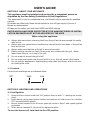
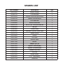
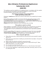
Glen Dimplex Professional Appliances: Salamander Grill (GB/IE) This appliance must be installed by a competent person in compliance with the installation and servicing instructions and national regulations in force at the time. Particular attention must be paid to the following: Gas Safety (Installation & Use) Regulations. Health and Safety at Work Act. Adjustment must not be made by the user to parts which are protected by the manufacturer. Users of this appliance should be conversant with the appropriate provisions of the Fire Precautions Act and the requirements of the Gas Safety Regulations, in particular, the need to service the appliance on a regular basis to ensure the continued safe and efficient performance of the appliance. Always ensure that a competent person undertakes any servicing. This appliance must be earthed After installation, the installer must ensure that the user is instructed on the safe use of this appliance, and has a copy of the user guide left with them for reference. This equipment is only for professional use, and should only be operated by qualified persons. It is the responsibility of the supervisor or equivalent to ensure that users wear suitable protective clothing and draw attention to the fact that, some parts will, by necessity become very hot and will cause burns if touched accidently. When using the appliance: DD Always take care when removing food from the grill as the area around the cavity may be hot. DD Always use oven gloves when handling any utensils which have been in the grill as they will be hot. DD Always make sure that the grill shelf is secured correctly. 88 Plastic cooking utensils can melt if they come into contact with the grill. Never leave them close to, or on top of the grill. 88 Do not wrap foil around the grill shelf. 88 Do not drape tea towels near the grill while it is on, this will cause a fire hazard. 88 Do not use this appliance to heat anything other than food items, and do not use for heating the room. These appliances must be installed and serviced by a competent person as stipulated by the Gas Safety (Installation & Use) Regulations IMPORTANT The installer must ensure that the installation of the appliance is in conformity with these instructions and National Regulations in force at the time of installation. Particular attention MUST be paid to • Gas Safety (Installation & Use) Regulations • Health And Safety At Work Act etc. • Local and National Building Regulations • Fire Precautions Act • Detailed recommendations are contained in Institute of Gas Engineers published documents: IGE/ UP/ 1, IGE/ UP/ 2 • BS6173 and BS5440 • I.S 820 Non-domestic Gas Installations These appliances have been CE-marked on the basis of compliance with the Gas Appliance Directive for the Countries, Gas Types and Pressures as stated on the Data Plate. Pay particular attention in order not to disturb the air combustion admission or the combustion products evacuation of the appliance. WARNING - TO PREVENT SHOCKS, ALL APPLIANCES WHETHER GAS OR ELECTRIC, MUST BE EARTHED. On completion of the installation, these instructions should be left with the Engineerin-Charge for reference during servicing. After installation / service these Instructions should be handed over to the User, having had a demonstration of the operation and cleaning of the Appliance. IT IS IMPORTANT THAT THESE INSTRUCTIONS BE CONSULTED BEFORE INSTALLING AND COMMISSIONING THIS APPLIANCE. FAILURE TO COMPLY WITH THE SPECIFIED PROCEDURES MAY RESULT IN DAMAGE OR THE NEED FOR A SERVICE CALL. PREVENTATIVE MAINTENANCE CONTRACT In order to obtain maximum performance from this unit we would recommend that a Maintenance Contract be arranged. Visits may then be made at agreed intervals to carry out adjustments and repairs. SECTION 1 - INSTALLATION UNLESS OTHERWISE STATED, PARTS WHICH HAVE BEEN PROTECTED BY THE MANUFACTURER ARE NOT TO BE ADJUSTED BY THE INSTALLER 1.1 NETT WEIGHT and DIMENSIONS WIDTH (mm) DEPTH (mm) HEIGHT (mm) WEIGHT (kg) GAS CONN. 785 362 370 25 3/4” BSP (female) The grill may be mounted on any of the following options: Feet (supplied), floor stand or wall bracket. 1.2 SITING There must be 150mm clearance all around the appliance from any combustable wall or object liable to damage when overheated. There must be a minimum vertical clearance of 900mm above the top edge of the flue to ensure no overheating of overlying combustible surfaces. A minimum clearance of 400mm from the sides should be provided to allow removal of outer panels for service access. Methods of mounting the appliance are available as detailed in Section 1.1. The appliance should not be mounted directly upon a table. Note: Upper sections of the unit are likely to become very hot. It should therefore be positioned in a manner which minimises the risk of accidental touching. 1.3 VENTILATION The appliance MUST be installed on a level, fireproof, well lit and draught free position. Adequate ventilation, whether natural or mechanical, must be provided to ensure sufficient air for combustion and removal of combustion products, which may be harmful to health. Recommendations for Ventilation of Catering Appliances are given in BS5440:2. For multiple installations the requirements for individual appliances should be added together. Installation should be made in accordance with local and/or national regulations applying at the time. A competent installer MUST be employed. The appliance discharges vertically through the vent at the top of the unit. There must be no direct connection of the flue to any mechanical extraction system or the outside air. Positioning the appliance below a ventilated canopy is the most suitable arrangement. WARNING Remember, dirty extraction filter and drip trays become combustible, hence the importance of adhering to the specified flue clearance distance to these items. Regular cleaning of extraction filters and drip trays must be carried out. 1.4 GAS SUPPLY The incoming service must be of sufficient size to supply full rate without excessive pressure drop. A gas meter is connected to the service pipe by the Gas Supplier. Any existing meter should be checked by the Gas Supplier to ensure that the meter is of adequate capacity to pass the required rate of the appliance in addition to any other gas equipment installed. Installation pipe work should be fitted in accordance with IGE/ UP/ 2. The pipe work should be of adequate size but not smaller than the gas inlet connection on the appliance, i.e. Rp 3/4” B.S.P. An isolating cock must be located close to the appliance to allow shut-down during an emergency or servicing of the gas supply. Tubing shall comply with the national requirements in force and shall be periodically examined and replaced as necessary. The installation must be tested for gas tightness. Details of this procedure can be found in IGE/ UP/ 1. 1.5 ELECTRICAL SUPPLY Not applicable to this appliance. 1.6 WATER SUPPLY Not applicable to this appliance. 1.7 HEAT INPUTS - NATURAL AND PROPANE GAS (kW net) Natural Gas 6.8 kW 0.72 m3/hr Propane Gas 6.8 kW 486 g/hr 1.8 INJECTOR AND BYPASS STAMPINGS - NATURAL AND PROPANE GAS 1.8.1 Injector stampings/size Natural Gas 21 2.10 mm Propane Gas 13 1.35 mm 1.8.2 Bypass screw stampings Natural Gas 85 (adj. out) Propane Gas 85 (screwed in) 1.9 GAS PRESSURE ADJUSTMENT - NATURAL AND PROPANE GAS The following supply pressures apply to all units. Natural Gas 20 mbar 8” w.g Propane Gas 37 mbar 14.8” w.g Pressure test point is located towards the centre of the gas manifold situated behind the RH side / control panel. Connect a manometer and check that the supply pressure is correct when the grill burner is ignited and turned to the full on setting. 1.10 BURNER ADJUSTMENT - NATURAL AND PROPANE GAS The grill burner has a fixed aeration aperture, NO ADJUSTMENT is possible. SECTION 2 - ASSEMBLY AND COMMISSIONING 2.1 ASSEMBLY 2.1.1 Grill Unit Unpack grill and check that all components are undamaged. Parts supplied loose are specified in the contents list below: Brander Plate Brander Drip Tray Grill Shelf Grill Shelf Handle / Shields (x2) Drip Tray Adjustable Feet (x4) 2.1.2 Appliance Mounting Accessories Details of various mounting options can be obtained by contacting GDPA Sales, distributor or place of purchase. Refer to the individual instructions supplied with the individual means of mounting. ADHERENCE TO THE POSITIONING CLEARANCES INDICATED IN SECTION 1.2 OF THIS MANUAL IS MANDATORY. 2.2 CONNECTION TO THE GAS SUPPLY Connect appliance to the gas supply. Test for gas tightness. The integral gas supply downstream of gas valve may be checked by applying leak detection spray with burner lit. Appliance inlet connection terminates at lower rear RH side in Rp3/4 (3/4” BSP female). 2.3 CONNECTION TO ELECTRICAL SUPPLY Not applicable to this appliance. 2.4 CONNECTION TO WATER SUPPLY Not applicable to this appliance. 2.5 COMMISSIONING THE APPLIANCE Important: Prior to operation, ensure ALL packing material has been removed from the appliance. 2.5.1 Setting the gas pressure a. It is necessary to check the gas pressure during commissioning and a suitable pressure gauge must be connected to the pressure test point towards the centre of the gas manifold located behind the RH side / control panel. b. Now turn on main gas valve supply to unit. c. Ignite the grill burner on the appliance as described in section 2.5.3. As gas supply pipes may contain air, continue to repeat lighting procedure until flame is established. Ensure that the supply pressure is as detailed in Section 1.9. d. Disconnect pressure gauge from test point. Replace test point sealing screw and test for gas tightness. 2.5.2 Checking the performance of the controls Light grill burner as detailed in Section 2.5.3. Check ignition is smooth and without delay. Repeat operation several times. 2.5.3 Lighting sequence Important: Prior to operation, ensure ALL packing material has been removed from the appliance. 1. Ensure mains gas is turned on. 2. To light grill burner, press and turn control knob until ‘off’ position lines up with ‘’ marking on control panel. Ignite burner using piezo ignition button located above the control knob. Hold in for 5 - 10 seconds and then release. Check that the burner remains lit and turn knob to required position. 2.6 INSTRUCTION TO USER Whenever possible, the installer should ensure that the user thoroughly understands the instructions for lighting, cleaning and correct use of the appliance. It is also important to ensure that the location of the gas isolating cock is made known to the user, and that the procedure in an emergency is demonstrated. SECTION 3 - SERVICING IMPORTANT: BEFORE ATTEMPTING ANY SERVICING, ENSURE ISOLATING COCK IS TURNED OFF AND CANNOT BE INADVERTENTLY TURNED ON. AFTER ANY MAINTENANCE TASK, CHECK APPLIANCE TO ENSURE THAT IT PERFORMS CORRECTLY AND CARRY OUT ANY NECESSARY ADJUSTMENTS AS DETAILED IN SECTION 1. After carrying out any service or exchange of gas carrying components ALWAYS CHECK FOR GAS TIGHTNESS 3.1 REMOVAL OF PLAQUES AND BURNERS 3.1.1 To Replace Damaged or Broken Plaques 1. 2. 3. 4. 5. 6. 7. Remove top front panel (3 screws) Remove top panel (2 screws) Remove grill cowl (6 screws) Unscrew plaque holder from grill burner (6 screws) Remove plaque to be replaced by opening up the fold down tabs Replace plaque and close fold down tabs Screw plaque holder back onto the grill burner and refit all panels that have been removed 3.1.2 To Replace Burner 1. Remove top front panel and top panel as detailed in section 3.1.1 2. Remove RH side panel (5 screws underneath, 3 screws rear and 1 screw front) 3. Remove LH side panel (3 screws underneath, 3 screws rear) 4. Remove grill cowl / plaque holder assy from grill burner (6 screws) 5. Unscrew injector supply pipe from injector 6. Unscrew injector carrier bracket from RH cavity side panel (2 screws) 7. Unscrew grill burner fixing from LH cavity side panel (1 screw) 8. Slide out infill piece and remove grill burner 9. Unscrew grill burner from injector carrier bracket (1 screw) 10. Replace in reverse order 3.2 INJECTORS 3.2.1 To Replace Injector 1. 2. 3. 4. 5. 6. Remove top front panel and top panel as detailed in section 3.1.1 Remove RH side panel as detailed in section 3.1.2 Unscrew injector supply pipe from injector Unscrew injector carrier bracket from RH cavity side panel (2 screws) Undo injector and remove Replace in reverse order 3.3 THERMOCOUPLE / FLAME FAILURE DEVICE (FFD) 3.3.1 Flame Failure Device Magnet Unit To remove and replace FFD magnet unit, the following procedures must be followed: 1. Undo thermocouple at FFD section of gas tap 2. Undo FFD section cap at rear of gas tap and withdraw magnet unit 3. Replace in reverse order 3.3.2 Thermocouple 1. Remove top front panel and top panel as detailed in section 3.1.1 2. Remove RH side panel as detailed in section 3.1.2 3. Remove nut securing thermocouple sensor to support bracket and pull thermocouple through support bracket from the rear 4. Undo thermocouple connection at FFD section of gas tap and carefully remove thermocouple. 5. Replace in reverse order, take care not to overtighten the thermocouple 3.4 GRILL IGNITER AND ELECTRODE Igniter is a piezo spark type and contains no batteries. Unit comprises piezo, housing, lead and electrode assembly. Lead is push-fit at piezo and electrode ends. 3.4.1 Igniter 1. 2. 3. 4. Remove top front panel and top panel as detailed in section 3.1.1 Disconnect earth wire and electrode lead from piezo housing Remove nut holding igniter in place and remove igniter Replace in reverse order 3.4.2 Electrode 1. Remove top front panel and top panel as detailed in section 3.1.1 2. Remove RH side panel as detailed in section 3.1.2 3. Disconnect igniter lead from electrode 4. Remove silicon grommet 5. Undo No 4 x 3/8” torx head screw securing electrode to bracket 6. Remove electrode and replace in reverse order Note: Care should be taken to not damage the electrode 3.7 GAS TAP Note: Plugs and bodies are machined in pairs and are, therefore, not interchangeable. 3.7.1 Removal of gas tap 1. 2. 3. 4. 5. 6. Remove top front panel and top panel as detailed in section 3.1.1 Remove control knob and RH side panel as detailed in section 3.1.2 Undo thermocouple connection at FFD section of gas tap Undo injector supply pipe at gas tap rear Undo fixings which secure tap to gas rail Replace all parts in reverse order, renewing the O-ring if necessary. Take care not to overtighten thermocouple connection at gas tap rear 3.8 FAULT CHECK LIST If a 1. 2. 3. 4. 5. 6. flame is not established follow this check list: Check mains gas is ON Check pressure at pressure test point to ensure gas is flowing to the appliance If gas is present then check burner injector for blockage If injector is OK then check FFD magnet unit is engaging and allowing gas to pass Check for spark at spark electrode If there is no spark then check spark gap and igniter lead connections. Also check igniter 7. If a flame is still not present then re-check from start If a flame is established but not maintained then follow this check list: 1. Check the thermocouple sensor is secured correctly and that the burner ports are clean 2. Check that the thermocouple is not damaged and is securely fixed to FFD section of the gas control 3. Check that the FFD is energising and maintaining the flame 4. If after carrying out the above, the burner is still not maintaining the flame check the magnet unit within the control SECTION 4 SPARES When ordering spare parts, always quote the appliance type and serial number. This information will be found on the data badge attached to the rear of the product. USER’S GUIDE SECTION 1 ABOUT YOUR APPLIANCE This appliance must be installed and serviced by a competent person as stipulated by the Gas Safety (Installation & Use) Regulations This equipment is only for professional use, and should only be operated by qualified persons. All models are fitted with flame failure devices to shut off gas supply to burner if flames are extinguished. All taps are the safety type with fixed HIGH and LOW settings PARTS WHICH HAVE BEEN PROTECTED BY THE MANUFACTURER OR INSTALLATION ENGINEER MUST NOT BE ADJUSTED BY THE USER When using the appliance: DD Always take care when removing food from the grill as the area around the cavity may be hot. DD Always use oven gloves when handling any utensils which have been in the grill as they will be hot. DD Always make sure that the grill shelf is secured correctly. 88 Plastic cooking utensils can melt if they come into contact with the grill. 88 88 88 Never leave them close to, or on top of the grill. Do not wrap foil around the grill shelf. Do not drape tea towels near the grill while it is on, this will cause a fire hazard. Do not use this appliance to heat anything other than food items, and do not use for heating the room. 1.1 Controls Control knob markings are as indicated below SECTION 2 LIGHTING AND OPERATIONS 2.1 Cold Ignition 1. Press and turn control knob until ‘off’ position lines up with ‘’ marking on control panel 2. Ignite burner using piezo ignition button and continue to hold knob in for a further 5-10 seconds before release 3. Burner should remain lit but if burner goes out return to Step 1 and repeat ignition procedure 4. When burner remains lit, turn knob to required position To turn the burner off, turn knob to the OFF position 2.2 Hot Ignition 1. Press and turn knob to full flame position 2. Ignite burner using piezo ignition button and continue to hold knob in for a further 5-10 seconds before release 3. Burner should remain lit but if burner goes out return to Step 1 and repeat ignition procedure 4. When burner remains lit, turn knob to required position To turn the burner off, turn knob to the OFF position SECTION 3 USING THE GRILL 3.1 Pre-heating If you prefer to cook your foods under a pre-heated grill, very hot conditions can be achieved after 15 minutes. However, toast can be inserted approximately 5 minutes after the appliance has been lit. 3.2 Drip Tray A drip tray is situated in the bottom of the cooking compartment. This should be kept in place at all times when the burner is ON. 3.3 Warning THE COOKING ZONE SHOULD BE SYSTEMATICALLY CHECKED AND CLEANED, PAYING PARTICULAR ATTENTION TO ANY GRILL PANS OR OTHER RECEPTACLES THAT MAY BE USED PRIOR TO LIGHTING TO AVOID THE RISK OF FIRE. DO NOT DRAPE TOWELS ETC. OVER THE APPLIANCE WHILST IT IS IN USE. SUCH ACTION COULD OBSTRUCT VENTILATION AND LEAD TO OVERHEATING. SECTION 4 COOKING HINTS GRILLING is a QUICK, SIMPLE and DIRECT method of cooking. Ideal for a wide and varied list of menu items, heat is transferred from the source in direct rays (radiation), onto the food required to be cooked. These foodstuffs can be placed on trays or alternatively, directly on the brander. The grill will accommodate a 1/1 gastronome tray. DUE TO THE DIRECT HEAT PRESENT DURING GRILLING, GREAT CARE SHOULD BE TAKEN WHEN COOKING FOOD. BE CAREFUL OF SPLASHES FROM HIGH FAT CONTENT FOODSTUFFS. EMPTY DRIP TRAY AND BRANDER DRIP TRAY FREQUENTLY. USE OF TONGS IS RECOMMENDED WHEN TURNING OR MOVING FOOD. SECTION 5 CLEANING AND MAINTENANCE All surfaces are easier to clean if spillages are removed before they become burnt on and if units are cleaned daily. Stainless steel surfaces These surfaces should be cleaned with hot water and detergent then dried and polished with a soft cloth. Cleaning agents containing bleach, abrasives or caustic chemicals will damage or mark the stainless steel surfaces and MUST NOT be used. Vitreous enamel surfaces Approved cleaning agents which have the mark of the Vitreous Enamel Development Centre are recommended. It is advisable to clean daily after use. Wipe clean the vitreous enamel surfaces while they are still warm using a soft cloth and hot soapy water. Badly stained, removably parts (i.e drip tray) should be soaked in hot water with an approved detergent, if the parts are not removable from the unit the application of warm water with approved detergent using nylon or scotch cleaning pads will give good results. Aluminium Brander The brander should be left under full heat of the grill. After a period this will carbonize spillage. Remove debris with a wire brush. Grill Shelf Steep grill shelf in hot soapy water, rub with a pan scrubber on stubborn stains. SPARES LIST Part Number Description Qty 083076900 Plaque (single) 6 082980700 Thermocouple 1 080125000 Locknut thermocouple BRASS 1 503095700 Bracket thermocouple 1 082544300 Grill electrode 1 503095800 Bracket electrode 1 082541700 No 4 x 3/8” torx pan head bz 1 083064902 Tap grill 1 082983800 Control knob 1 081502200 Generator ignition piezo black 1 083076700 Handle shield 2 083076600 Handle 2 083075800 Grill shelf 1 083076500 Brander plate 1 083077300 Burner 1 082321500 Adaptor grill jet 1 082837803 Injector (Natural gas) 1 082837804 Injector (Propane gas) 1 533075900 Brander drip tray 1 533076000 Drip tray 1 503075200 Plaque holder 1 082983900 FOOT (adjustable) 4 083117700 Handbook 1 Glen Dimplex Professional Appliances Stoney Lane, Prescot, Merseyside, L35 2XW Tel: 0844 815 3755 08 31177 00 © 10.2010