1
S
A
N
J O
P r o f e s s i o n a l
S
E
i n
N
N
A
V
a v i g a t i o n
I G
&
C
A
o m
T
m
I O
N , I N
u n i c a t i o n
GPS Receiver Module
FV-17
User Manual
Version A
Please read this manual before operating the unit
June 5, 2002
© San Jose Navigation, Inc.
SANJOSE NAVIGATION,INC.
9F NO. 105 SHI-CHENG ROAD, PAN-CHIAO CITY
TAIPEI HSIEN, TAIWAN, R.O.C.
TEL: 886-2-26879500
FAX: 886-2-26878893
WWW.SANAV.COM
ISO 9001
NO. T2000-351
C .
2
S
A
N
J O
P r o f e s s i o n a l
S
E
i n
N
N
A
V
a v i g a t i o n
I G
&
C
A
o m
T
m
I O
N , I N
u n i c a t i o n
Content
Chapter 1
1.1
1.2
1.3
Chapter 2
2.1
2.2
Overview ................................................................................................4
Introduction of FV-17 ................................................................4
What is GPS? .............................................................................4
What is DGPS? ..........................................................................6
Specification ..........................................................................................7
General Specification.................................................................7
System Layout ...........................................................................8
2.2.1 Pin Assignment ..................................................................................8
2.2.2 GPS Module FV-17............................................................................8
2.3
Module System Layout ..............................................................9
2.3.1 Pin Assignment ..................................................................................9
Chapter 3
Software Installation & Operation .......................................................10
3.1
Install SANAV.EXE ................................................................10
3.1.1 Procedures:.......................................................................................10
3.1.2 Setting Up Log Output Intervals:.....................................................11
Chapter 3
Software Specification .........................................................................15
3.1
Communication Specification..................................................15
3.2
About NMEA-0183 Protocol...................................................16
3.2.1 Approved Sentences.........................................................................16
3.2.2 Proprietary Sentences.......................................................................17
3.3
List of NMEA-0183 Sentences ................................................18
3.4
List of Parameters & Backed-up Data .....................................20
3.5
NMEA-0183 Input Sentences ..................................................21
3.5.1 $XXGLL(in) ....................................................................................21
3.5.2 $XXGGA(in) ...................................................................................22
3.5.3 $XXZDA(in)....................................................................................23
3.5.4 $XXRMC(in) ...................................................................................24
3.5.5 $PFEC,GPclr(in ).............................................................................26
3.5.6 $PFEC,GPset(in)..............................................................................27
3.5.7 $PFEC,GPsrq(in) .............................................................................29
3.5.8 $PFEC,GPint(in)..............................................................................30
3.5.9 $PFEC,GPirq(in)..............................................................................32
3.5.10 $PFEC,GPdif(in)............................................................................33
3.5.11 $PFEC,GPdrq(in)...........................................................................34
3.6
NMEA-0183 Output Sentences ...............................................35
3.6.1 $GPGGA (out) .................................................................................35
C .
3
S
A
N
J O
P r o f e s s i o n a l
3.6.2
3.6.3
3.6.4
3.6.5
3.6.6
3.6.7
3.6.8
3.6.9
3.6.10
3.6.11
3.6.12
3.6.13
3.6.14
3.6.15
3.6.16
3.6.17
3.6.18
S
E
i n
N
N
A
V
a v i g a t i o n
I G
&
C
A
o m
T
m
I O
N , I N
u n i c a t i o n
$GPZDA (out)..................................................................................37
$GPGLL (out) ..................................................................................38
$GPGSA (out)..................................................................................39
$GPGSV (out)..................................................................................40
$GPVTG (out) .................................................................................41
$GPRMC (out).................................................................................42
$GPDTM (out).................................................................................44
$PFEC,GPanc (out)..........................................................................45
$PFEC,GPacc (out)........................................................................46
$PFEC,GPast (out).........................................................................47
$PFEC,GPtst (out) .........................................................................49
$PFEC,GPssd (Answer to $PFEC,GPsrq) .....................................51
$PFEC,GPisd (Answer to $PFEC,GPirq)......................................52
$PFEC,GPdsd (Answer to $PFEC,GPdrq) ....................................53
$PFEC,GPdie (out) ........................................................................54
$PFEC,GPspe,ANCOUT (in) ........................................................56
$PFEC,GPspe,ANCINP (in) ..........................................................57
3.7
Geodetic ID ..............................................................................58
Chapter 4
Glossary ...............................................................................................66
4.1
Common Terms:.......................................................................67
Chapter 5
Troubleshooting ...................................................................................69
Chapter 6
WARRANTY.......................................................................................70
C .
4
S
A
N
J O
P r o f e s s i o n a l
S
E
i n
N
N
A
V
a v i g a t i o n
I G
&
C
A
o m
T
m
I O
N , I N
u n i c a t i o n
Chapter 1 Overview
Congratulations on the purchase of FV-17, a new member of our successful GPS
receiver module family. You will find the device an accurate, reliable and useful aid
to your positioning pursuits.
1.1
Introduction of FV-17
FV-17 is a single -board 12 parallel-channel Global Positioning System (GPS)
receiver module that can be integrated on a wide variety of OEM GPS products. The
receiver tracks up to 12 Satellites providing 3D accuracy and in small package suitable
for hand-held or mobile products. FV-17, one of our high performance receivers, is
especially designed with maximum flexibility in today's wide range of OEM modules
for in -vehicle automotive products.
The module minimal operation requires regulated power and L1 band GPS signal
1575.42MHz from our ACTIVE external antenna or similar with at least 26dB of
antenna gain. One serial port is provided with FV-17 module for DATA output
position, velocity, time and also status information for PC software interface
parameters.
Before introducing you our new receiver, we would like to give you some basic
background knowledge about GPS, which should be helpful for you to better
understand your FV-17.
1.2
What is GPS?
GPS (Global Positioning System) is a satellite-based global navigation system
created and operated by the United States Department of Defense (DOD). Originally
intended solely to enhance military defense capabilities, GPS capabilities have
expanded to provide highly accurate position and timing information for many
C .
5
S
A
N
J O
P r o f e s s i o n a l
S
E
i n
N
N
A
V
a v i g a t i o n
I G
&
C
A
o m
T
m
I O
N , I N
u n i c a t i o n
civilian applications.
An in-depth study of GPS is required to fully understand how it works, but
simply stated: Twenty four satellites in six orbital paths circle the earth twice each day
at an inclination angle of approximately 55 degrees to the equator. This constellation
of satellites continuously transmit coded positional and timing information at high
frequencies in the 1500 Megahertz range. GPS receivers with antennas located in a
position to clearly view the satellites, pick up these signals and use the coded
information to calculate a position in an earth coordinate system.
GPS is the navigation system of choice for today and many years to come. While GPS
is clearly the most accurate worldwide all-weather navigation system yet developed, it
still can exhibit significant errors. GPS receivers determine position by calculating the
time it takes for the radio signals transmitted from each satellite to reach earth. It’s
that old "Distance = Rate x Time" equation. Radio waves travel at the speed of light
(Rate). Time is determined using an ingenious code matching technique within the
GPS receiver. With time determined, and the fact that the satellite’s position is
reported in each coded navigation message, by using a little trigonometry the receiver
can determine its location on earth.
Position accuracy depends on the receiver’s ability to accurately calculate the
time it takes for each satellite signal to travel to earth. This is where the problem lies.
There are primarily five sources of errors which can affect the receiver’s calculation.
These errors consist of (1) ionosphere and troposphere delays on the radio signal, (2)
signal multi-path, (3) receiver clock biases, (4) orbital errors, also known as
ephemeris errors of the satellite's exact location, and (5) the intentional degradation of
the satellite signal by the DOD. This intentional degradation of the signal is known as
"Selective Availability (SA)" and is intended to prevent adversaries from exploiting
highly accurate GPS signals and using them against the United States or its allies.
However, on May 1, 2000, U.S. President Bill Clinton ordered Selective Availability
(SA) turned off at midnight (Coordinated Universal Time). Now, civilian GPS users
around the world will no longer experience the up to 100 meter (approximate 300 feet)
random errors that SA added to keep GPS a more powerful tool for the military. Today,
GPS units are accurate to within 20 meters (approximately 60 feet); although in good
conditions, units should display an error of less than 10 meters. The combination of
these errors in conjunction with poor satellite geometry can limit GPS accuracy to 100
meters 95% of the time and up to 300 meters 5% of the time. Fortunately, many of
these errors can be reduced or eliminated through a technique known as
"Differential."
C .
6
S
A
N
J O
P r o f e s s i o n a l
1.3
S
E
i n
N
N
A
V
a v i g a t i o n
I G
&
C
A
o m
T
m
I O
N , I N
u n i c a t i o n
What is DGPS?
DGPS works by placing a high-performance GPS receiver (reference station) at a
known location. Since the receiver knows its exact location, it can determine the
errors in the satellite signals. It does this by measuring the ranges to each satellite
using the signals received and comparing these measured ranges to the actual ranges
calculated from its known position. The difference between the measured and
calculated range is the total error. The error data for each tracked satellite is formatted
into a correction message and transmitted to GPS users. The correction message
format follows the standard established by the Radio Technical Commission for
Maritime Services, Special Committee 104 (RTCM-SC104) These differential
corrections are then applied to the GPS calculations, thus removing most of the
satellite signal error and improving accuracy. The level of accuracy obtained is a
function of the GPS receiver.
C .
7
S
A
N
J O
P r o f e s s i o n a l
S
E
i n
N
N
A
V
a v i g a t i o n
I G
&
C
A
o m
T
m
I O
N , I N
C .
u n i c a t i o n
Chapter 2 Specification
2.1
General Specification
PERFORMANCE
ELECTRICAL CHARACTERISTICS
Architecture: 12 channels (All-in-views)
Input Voltage: +5Vdc +/-5%
Receiver Frequency: 1575.42 MHz
Power Consumption (typical): 0.65 W typically
C/A code: 1.023 MHz chip rate
Backup: +2.5Vdc to +5.5Vdc
Tracking Sensitivity: -133dBm
TIME TO FIRST FIX
INTERFACE I/O
Cold start average: <95sec
Compatibility: One full duplex serial
Warm start average: <12sec
Data Rate: 4800bps
RECEIVER ACCURACY
Format: NMEA-0183, version 2.3
Position: 15meter or 50 feet
Standard Output Sentences:
Velocity: 0.1 km/h
GGA,GLL,GSA,GSV,RMC & VTG
UTC-Sync Pulse: +/-1 μs to UTC
Default Sentences:
GGA,ZDA,DTM,GSV & VTG
DGPS ACCURACY
*San Jose Navigation, Inc. may add other NMEA
Position Accuracy: 1 to 2 meters, with DOP<3
sentences to the standard output to maximize interfacing
DGPS input baud rate: 4,800bps
capabilities
DGPS: RTCM SC-104, version 2.1
Time-1PPS Pulse
DYNAMIC CONDITION
Level: TTL
Velocity: 515 m/sec. (1000 knots) max.
Velocity: 0.05 m/sec. (typically)
2
Acceleration: >49m/s (sustained tracking)
Pulse duration: 1sec
Time reference: At the pulse negative edge
Altitude: 18,000 meters (60,000 feet) max
Measurements: Aligned to GPS second, +/- 1
microsecond
ENVIRONMENTAL CONDITION
COMMUNICATION
Temperature
Output Protocol: NMEA 0183 at 4800bps
Operating range: -40℃ to + 85℃
Signal Level: TTL
Datum WGS-84 plus 250 + user selectable
Interface Connector: 7-pin Molex connector, shipped
Storage range: -55℃ to + 100℃
with its mating connector
PHYSICAL CHARACTERISTICS
Dimension: 44mm(L) x 26mm(W) x 7mm(H)
Weight: ~16g
Antenna connector: MMCX
8
S
A
N
J O
P r o f e s s i o n a l
2.2
S
E
i n
N
N
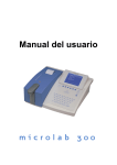
System Layout
1PPS (TTL)
TX (GPS Data TTL)
RX or DGPS-IN (9.6K)
GND
V-BATT
V-ANT
Vcc
2.2.2 GPS Module FV-17
Signal
1PPS
TX
RX
GND
Vbak
Vcc
V
a v i g a t i o n
2.2.1 Pin Assignment
1.
2.
3.
4.
5.
6.
7.
A
Function
1 pulse/sec out
GPS data out/TTL
Data In/DGPS-in 9.6K
System ground
SRAM Back-up
System supply
I G
&
C
A
o m
T
m
I O
N , I N
u n i c a t i o n
C .
9
S
A
N
J O
P r o f e s s i o n a l
2.3
E
i n
N
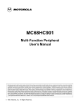
Module System Layout
2.3.1 Pin Assignment
1.
2.
3.
4.
5.
6.
7.
S
1PPS (TTL)
TX (GPS Data TTL)
RX or DGPS-IN (9.6K)
GND
V-BATT
V-ANT
Vcc
N
A
V
a v i g a t i o n
I G
&
C
A
o m
T
m
I O
N , I N
u n i c a t i o n
C .
10
S
A
N
J O
P r o f e s s i o n a l
S
E
i n
N
N
A
V
a v i g a t i o n
I G
&
C
A
o m
T
m
I O
N , I N
u n i c a t i o n
Chapter 3 Software Installation &
Operation
3.1
Install SANAV.EXE
Sanav.exe is a utility program that works in conjunction with FV-17. You have
to install this program to your computing device first before operating FV-17.
3.1.1 Procedures:
1.
Download Sanav.exe from our website at http://www.sanav.com/software.htm:
2.
The File Download window appears. Select “Save this program to disk” and
then click OK:
C .
11
S
A
N
J O
P r o f e s s i o n a l
S
E
i n
N
N
A
V
a v i g a t i o n
I G
&
C
A
o m
T
m
I O
N , I N
u n i c a t i o n
3.
In the following Save As window, save the Savav.exe in your system by clicking
the “Save in” dropdown list. In our example, we choose to save the program in
Program Files:
4.
When the Download complete window appears, click Open: (Note: You must
leave the “Close this dialog box when download completes” unchecked.)
5.
A black window flashes for one or two seconds and then disappears. Please
ignore this. The Sanav.exe has already been saved to your system by now.
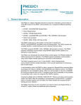
3.1.2 Setting Up Log Output Intervals:
1.
Click Start
Programs
Command Prompt for Windows 95/98/Me; Click
Start
Programs
Accessories
Command Prompt for Windows 2000
Professional/Server
2.
Key in sanav and press Enter to run SANAV.exe, which is supposed to have
saved in your system drive. In our example the drive is D, as shown below:
C .
12
S
A
N
J O
P r o f e s s i o n a l
S
E
i n
N
N
A
V
a v i g a t i o n
I G
&
C
A
o m
T
m
I O
N , I N
u n i c a t i o n
Key in “sanav” just next to
the name of your system
drive.
Press Enter
3.
Press any key to enter a setup screen, as shown below, to configure various
NMEA 0183 Protocol intervals for FV-17:
C .
13
S
A
N
J O
P r o f e s s i o n a l
4.
S
E
i n
N
N
A
V
a v i g a t i o n
I G
&
C
A
o m
T
m
I O
N , I N
u n i c a t i o n
Key in any number ranging from 00-60 and then press Enter for each protocol
interval, as shown below:
Note: To disable an interval, key in 00.
5.
At the middle of the screen there is a sentence asking you to tell the program
which Com Port you are using to connect FV-17. In our example, it is Com 1
and thus we key in 1 here and then press Enter. By now we have successfully
interval configuration, and a screen will then appear to show that FV-17 is
receiving GPS signals, in the form of NMEA 0183 protocol, according to the
intervals you have just configured.
Default Protocol:
$GPDTM
Note: There is a default protocol of the program, $GPDTM, as surrounded by a
red rectangular frame in the diagram above. This protocol is automatically
generated by the program itself, and thus you can just ignore it.
6.
7.
To leave the program, press ESC and then either key in exit or click the
button at the screen’s top right side.
You are now ready to evaluate your new 12 channels GPS module according to
C .
14
S
A
N
J O
P r o f e s s i o n a l
S
E
i n
N
N
A
V
a v i g a t i o n
I G
&
C
A
o m
T
m
I O
N , I N
u n i c a t i o n
your new input.
Note: For a prompt TTF during warm start, a battery backup must be in place to
power up the RAM and keep it alive.
C .
15
S
A
N
J O
P r o f e s s i o n a l
S
E
i n
N
N
A
V
a v i g a t i o n
I G
&
C
A
o m
T
m
I O
N , I N
u n i c a t i o n
Chapter 3 Software Specification
3.1
Communication Specification
System:
Speed:
Start Bit:
Data Length:
Stop Bit:
Parity Bit:
Start Bit
B0
B1
Full Duplex Asynchronous
4800 bps
1 bit
8 bits (MSB=0)
1 bit
None
B2
B3
B4
B5
B6
B7
Stop Bit
Flow Control:
None
Signal Lines used:
TD1 and RD1 only (TD2 and RD2 not
used)
0 to 2 seconds
Data Output Interval:
Character Codes used
NMEA-0183 Sentences:
Different GPS Data:
ASCII (HEX 0D, 0A, 20 to 7E)
Binary (“6-of-8” format)
(B7=0, B6=1, Only B5 to B0 are used.)
Electrical specification similar to RS-232C
Protocol:
NMEA-0183 Sentences:
NMEA-0183 Ver 2.30 dated March 1,
1998 (Approved / Proprietary sentences)
Differential GPS Data:
RTCM SC-104 Ver 2.1 dated January 3,
1994 (Input only)
Note: NMEA-0183 sentence and differential GPS data inputs may coexist
because the GN79 can distinguish them automatically.
C .
16
S
A
N
J O
P r o f e s s i o n a l
3.2
S
E
i n
N
N
A
V
a v i g a t i o n
I G
&
C
A
o m
T
m
I O
N , I N
u n i c a t i o n
About NMEA-0183 Protocol
3.2.1 Approved Sentences
Approved sentences are those of which formats are defined and fixed within the
NMEA-0183 standard. Any portion within an approved sentence format is NOT
user-definable. An approved sentence generally takes the following form:
$<address field>,<data field>…【*<checksum field>】<CR><LF> Where:
Field
$
<address field>
Description
Start-of-Sentence marker
5-byte fixed length. First 2 bytes represent a talker ID, and the rest 3
bytes do a sentence formatter.
All sentences transmitted by FV-17 bear talker ID "GP" meaning a GPS
receiver.
For the sentences received from external equipment, the FV-17 accepts
any talker ID. Talker ID "XX" found on the succeeding pages is a
wildcard meaning "any valid talker ID."
,<data field>…
Variable or fixed-length fields preceded by delimiter "," (comma).
Commas are required even when valid field data are not available, i.e.,
null fields. Ex. ",,,,,"
In a numeric field with fixed field length, fill unused leading digits with
zeroes. (Do not support leading zeroes.)
*<checksum field>
8-bit data between "$" and "*" (excluding "$" and "*") are XORed,
and the resultant value is converted to 2 bytes of hexadecimal letters.
Note that two hexadecimal letters must be preceded by "*", and
delimiter "," is not required before *<checksum>.
For input sentences, *<checksum> is ignored.
<CR><LF>
End-of-Sentence marker
Maximum length from "$" to <CR><LF> is limited to 82 bytes including "$" and
<CR><LF>. Every input sentence in and over 83 bytes is ignored. Be careful with
entering GPset and GPint sentences. Suggest to verify if the input is done correctly by
issuing GPsrq, GPirq, GPdrq sentences.
Examples of Approved Sentences:
$GPGLL, 3444.000,N, 13521.00,E, E<CR><LF>
$XXGLL, 3444.000,N, 13521.00,E, E<CR><LF>
C .
17
S
A
N
J O
P r o f e s s i o n a l
S
E
i n
N
N
A
V
a v i g a t i o n
I G
&
C
A
o m
T
m
I O
N , I N
u n i c a t i o n
"XX" may be any valid talker ID, such as "LC" (Loran C).
3.2.2 Proprietary Sentences
The NMEA-0183 standard allows nav-aid makers to send proprietary sentences if
the minimum rules defined by the NMEA are obeyed. Proprietary sentences must
take the following form, but it is free to makers what kind of fields are included and
in what order they are transmitted out.
$P<maker ID>, <data field>…<*check sum field><CR><LF> where:
Field
Description
$
Start-of-Sentence marker
P
Proprietary sentence identifier
<maker ID>
3-byte fixed length
FV-17’s maker ID is "FEC' meaning Furuno Electric Company.
, <data field>
Variable or fixed-length fields preceded by delimiter "," (comma).
(Layout is maker-definable.)
<check sum field>
8-bit data between “$” and “*” (excluding “$” and “*”) are XORed,
and the resultant value is converted to 2 bytes of hexadecimal letters.
Note that two hexadecimal letters must be preceded by “*”, and
delimiter “,” is not required before *<checksum>.
For input sentences, *<checksum> is ignored.
<CR><LF>
End-of-Sentence marker
C .
18
S
A
N
J O
P r o f e s s i o n a l
3.3
S
E
i n
N
N
A
V
a v i g a t i o n
I G
&
C
A
o m
T
m
I O
N , I N
u n i c a t i o n
List of NMEA-0183 Sentences
The following NMEA-0183 sentences are supported by FV-17.
Input Sentence
Output Sentence
High
GPDTM
Datum
XXGGA
Set initial position
GPGGA
Position, time, etc.
OO
XXZDA
Set time, etc.
GPZDA
Time, etc.
OO
XXGLL
Set initial position
GPGLL
Position, time, etc.
O
GPGSA
Status, DOP
O
GPGSV
Satellite details
OO
GPVTG
Speed, Course.
OO
XXRMC
Set initial position, time GPRMC
GPalt
Position, time, speed, course O
No. of satellites expected in O
coming 24 hours
Priorit
GPanc
Date of existing almanac
O
GPacc
SV accuracy
O
GPast
GPS fix (position, local O
time)
GPtst
GPsrq
Selftest result
O
receiver GPssd
Answer to GPsrq
A
output GPisd
Answer to GPirq
A
Send DGPS parameters GPdsd
Answer to GPdrq
A
DGPS status
O
Send
GPS
parameters
Gpirq
Send
data
interval
GPdrq
Gpdie
GPclr
Restart
GPset
Set rx parameters
GPint
Set
sentence
output
interval
Low
GPdif
Note 1:
Set DGPS parameters
Higher priority data is output first, from top to bottom. (Highest priority:
GGA for example).
GPDTM is always output in front of each of GGA, GLL, RMC, GPast
sentence.
O
Sentence output interval is adjustable but if the back up is lost, the
sentence will not be output.
C .
19
S
A
N
J O
P r o f e s s i o n a l
OO
S
E
i n
N
N
A
V
a v i g a t i o n
I G
&
C
A
o m
T
m
I O
N , I N
u n i c a t i o n
Sentence output interval is adjustable and if the back up is lost, it goes
back to the default value, which is one second interval.
A
Sentence is output as an answer.
XX
Any talker ID
C .
20
S
A
N
J O
P r o f e s s i o n a l
3.4
S
E
i n
N
N
A
V
a v i g a t i o n
I G
&
C
A
o m
T
m
I O
N , I N
C .
u n i c a t i o n
List of Parameters & Backed-up Data
Data
Default
Range
Estimated position Lat. & Yes
Long.
N34deg. 44.0000 min.
E135deg.21.0000 min.
S90deg. to N90deg.
W180deg. to E180deg.
Time
Yes
1997 Jan. 1 0h. 0m. 12s 1997 Jan. 1 through
2040 Dec. 31
Altitude
Yes
0m
-999.9m to 17999.9m
Almanac data
Yes
---
---
Almanac date
Yes
1980 Jan. 6 0h. 0m. 0s
---
Ephemeris
Yes
---
---
Local Zone Time
Yes
+0h
-13h0m to +13h0m
PDOP value
Yes
6
0 to 10
Elevation Angle Mask
Yes
5 deg.
5 to 90 deg.
Geodetic ID
Yes
1 (WGS84)
1 to 171
Mask by Elevation Angle for Yes
Receivalbe
Satellites
Prediction
5 deg.
5 to 90 deg.
Mask by Signal Strength
No
1 dBHz (No mask)
1 to 99 dBHz
1PPS Correction
Yes
0µsec
-999.9µsec
+999.9µsec
to
Delete Satellites
No
00000000
00000000
FFFFFFFF
to
Smoothing Index
No
2
1 to 3
Dynamic Index
No
2
1 to 3
Data Output Interval
Yes
DTM, GGA, ZDA, GSV, 0-60 seconds (Only for
VTG (Every second)
those sentences that are
adjustable.)
DGPS parameter
Yes
1 (LSB first)
Backed
-up
GPS Data
Parameters
1 (LSB first)
2 (MSB first)
21
S
A
N
J O
P r o f e s s i o n a l
3.5
S
E
i n
N
N
A
V
a v i g a t i o n
I G
&
A
C
o m
T
m
I O
N , I N
C .
u n i c a t i o n
NMEA-0183 Input Sentences
3.5.1 $XXGLL(in)
Set initial position
This sentence sets the initial latitude/longitude. The position data will be updated when
position fixing begins.
Example
$XXGLL
Field#
,3444.123,N ,03521.5,E
1
2
#.
Description
1-2. Latitude
“34”: degree
“44”: minute (integer)
“123”: minute (fraction)
“N”: North/South
3-4. Longitude
“035”: degree
“21”: minute (integer)
“5”: minute (fraction)
“E”: East/West
3
4
, , ,
567
4D
8
Range
【Bytes】
00-90
00-59
0-9999
【2】
【2】
【variable】
N or S
see Note.
【1】
【3】
【2】
000-180
00-59
0-9999
[variable]
E or W
see Note.
【1】
Note: Digits below 1/10000 are ignored.
5-7. Null Fields
Any entry is ignored.
8.
Checksum
Interpreting Example:
34 deg 44.123 min N
35 deg 21.5 min E
CR LF
【2】
22
S
A
N
J O
P r o f e s s i o n a l
S
E
i n
N
N
A
V
a v i g a t i o n
I G
&
C
A
o m
T
m
I O
N , I N
C .
u n i c a t i o n
3.5.2 $XXGGA(in)
Set initial position
This sentence sets the initial latitude/longitude. The position data will be updated when
position fixing begins.
Example
$XXGGA
,
Field#
1
#.
,3444.123,N ,03521.5,E
2
Description
2-3. Latitude
“34”: degree
“44”: minute (integer)
“123”: minute (fraction)
“N”: North/South
4-5. Longitude
“035”: degree
“21”: minute (integer)
“5”: minute (fraction)
“E”: East/West
3
4
,,,,,,,,,
5
6-14
CR LF
15
Range
【Bytes】
00-90
【2】
00-59
0-9999
【2】
【variable】
N or S
see Note.
【1】
000-180
00-59
0-9999
【3】
【2】
【variable】
E or W
see Note.
【1】
Note: Digits below 1/10000 are ignored.
6-14. Null Fields
Any entry is ignored.
15. Checksum
Interpreting Example:
34 deg 44.123 min N
35 deg 21.5 min E
79
【2】
23
S
A
N
J O
P r o f e s s i o n a l
S
E
i n
N
N
A
V
I G
a v i g a t i o n
&
C
A
T
o m
m
I O
N , I N
C .
u n i c a t i o n
3.5.3 $XXZDA(in)
Set date/time
Example
$XXZDA
,123456
Field#
1
,01
,02
2
3
,1997 ,-09 ,00
4
5
6
79
7
#. Description
Range
【Bytes】
1. UTC: Time
“12”: hh
“34”:mm
“56”: ss
2. UTC: Date
00-23
00-59
00-59
【2】
【2】
【2】
01-31
【2】
01-12
【2】
1997-2040
【4】
-13…+00…+13
(-/+: East/West of date line)
【3】
00 to 59
【2】
“01”: DD
3. UTC: Month
“02”: MM
4. UTC: Year
“1997”: YYYY
5. Local
Zone
(Hour)
“-09”: hh
6. Local
Zone
(Minute)
“00”: mm
Note:
Time
Time
Local zone time setting is used for calculating local time
when outputting GPS fix ($PFEC,GPast):
(Local Time)=(UTC) – (Local Zone Time)
7. Checksum
Interpreting Example:
February 1, 1997
12:34:56
Local Zone Time: -09:00
【2】
CR LF
24
S
A
N
J O
P r o f e s s i o n a l
S
E
i n
N
N
A
V
a v i g a t i o n
I G
&
C
A
T
o m
m
I O
N , I N
C .
u n i c a t i o n
3.5.4 $XXRMC(in)
Set initial position/UTC
Example
$XXRMC
,123456
Field#
1
69
,
,3444.123,N
2
3
4
,13521.456,E
5
,,
,020197
…
9
10 11 12
6 78
CR LF
13
#.
Description
Range
【Bytes】
1.
UTC: Time
“12”: hh
“34”:mm
00-23
00-59
【2】
【2】
【2】
2.
3-4.
5-6.
“56”: ss
Null Field
Latitude
“34”: degree
“44”: minute (integer)
“123”: minute (fraction)
00-59
Any entry is ignored.
00-90
00-59
0-9999
【2】
【2】
【 variable 】
See
“N”: North/South
Longitude
“135”: degree
“21”: minute (integer)
N or S
Note
【1】
000-180
00-59
【3】
【2】
“456”: minute (fraction)
0-9999
【 variable] 】 See
E or W
Note
【1】
“E”: East/West
Note: Digits below 1/10000 are ignored.
7-8.
Null Fields
Any entry is ignored.
9.
UTC: Date
“02”: DD
01-31
“01”: MM
01-12
“97”: YY
97-40
(1997-2040)
10-12. Null Fields
Any entry is ignored.
13.
Checksum
Interpreting Example:
【2】
【2】
【2】
【2】
25
S
A
N
J O
P r o f e s s i o n a l
January 2, 1997
12:34:56
34 deg. 44.123 min. N
deg. 21.456 min. E
S
E
i n
N
N
A
V
a v i g a t i o n
I G
&
C
A
o m
T
m
I O
N , I N
u n i c a t i o n
C .
26
S
A
N
J O
P r o f e s s i o n a l
S
E
i n
N
N
A
V
a v i g a t i o n
I G
&
C
A
o m
T
m
I O
N , I N
C .
u n i c a t i o n
3.5.5 $PFEC,GPclr(in )
Restart
Example
$PFEC
,GPclr
Field#
,1
1
4B
2
CR LF
3
This sentence clears the data in the GPS receiver and restarts the receiver. The restart
works in the same way as the power is first on.
#. Description
【Bytes】
Range
1. Command Name
2. Mode
1-3
“1”: Clear mode 1
“2”: Clear mode 2
“3”: Clear mode 3
【5】
【1】
【2】
3. Checksum
Clear Mode
Receiver Data
1
2
3
Backed-up
used
value Backed-up
used
value
value Backed-up
used
value Backed-up
used
value
Latitude/Longitude
Returned to default
Time
Backed-up
used
Almanac Data
Deleted
Backed-up
used, if valid
value Deleted
Ephemeris Data
Deleted
Backed-up
used, if valid
value Deleted
Receiver Parameters All
parameters Backed-up
returned to default used
(Note 1)
value Backed-up
used
value
Note 1: Receiver parameters are those set by “$PFEC, GPset” sentence. Refer to the
“3.4. List of Parameters & Backed-up data” to see whether the value set by the
sentence is backed up or not.
Interpreting Example:
Clear mode 1
27
S
A
N
J O
P r o f e s s i o n a l
S
E
i n
N
N
A
V
a v i g a t i o n
I G
&
C
A
o m
T
m
I O
N , I N
C .
u n i c a t i o n
3.5.6 $PFEC,GPset(in)
Setup receiver parameters
Example
$PFEC ,GPset
Field#
#.
1.
2.
3.
4…….
1
,D05
,U00200000
……
2
3
4……
Description
Command Name
hh
CR LF
Range
【Bytes】(Unit) {Default}
【5】120
Up to eight parameters in any order preceded by delimiter “,” (comma). See
parameter syntax below:
“Dnn”:
Note: Do not send same parameters twice within the same sentence.
【3】(n/a) {D06}
PDOP Threshold
D00-D10
In 3D positioning mode, 2D positioning is forced when PDOP is higher than
this threshold. If D00 is set, 3D positioning is not performed. In 2D
“Enn”:
positioning, the altitude is not updated and the same altitude is continuously
output as set at the first 2D positioning.
Elevation Angle Mask for Receivable Satellite Prediction
【3】(deg.) {E05}
E05-E90
As the function of “Receivable Satellite Prediction” is deleted in this
model, this parameter setting is neglected.
“Gnn”:
“Hnnnnnn.n”:
“Mnn”:
“Snn”:
Geodetic ID
Altitude for 2D positioning
G001-G171
H-00999.9 to H017999.9
【4】(n/a) {G001}
【9】(meter) {H000000.0}
Note: When 3D positioning is performed, this data is updated.
【3】(degree) {M05}
Mask by Elevation Angle
M05-M90
Any satellites below this angle are ignored when
positioning.
【3】(dBHz) {S01}
Mask by Signal Strength
S01-S99
Any satellites weaker than this level are ignored
when positioning. The maximum level is
“Tnnnn”:
practically limited by the lowest tracking signal
level (38 dBHz).
1PPS Correction
T-9999 to T+9999 【6】(x0.1 µs) {T+0000}
28
S
A
N
J O
P r o f e s s i o n a l
S
E
i n
N
N
A
V
a v i g a t i o n
I G
&
C
A
o m
T
m
I O
N , I N
C .
u n i c a t i o n
0.1µs corresponds 30-meter antenna length. Note
that negative setting advances 1PPS pulses.
U00000000 – UFFFFFFF 【9】(n/a) {n/a}
“Uhhhhhhhh”: Delete satellites.
hhhhhhhh means eight hexadecimal letters, representing a bit map of 32 bits.
Each bit within the bit map represents one satellite; 0000001 and 8000000,
for example, indicate satellite SV#1 and SV#32, respectively.
Example: “PFEC,GPset,U0000000F” <CR><LF> declares unhealthy
satellites SV#1 to SV#4.
Satellites declared by this sentence are ignored when positioning. It should
be noted that satellites with their bits cleared are declared as “healthy”. In the
above example, satellites SV#5 to SV#32 are implicitly declared as
“healthy”.
In the following example, the first sentence declares satellite SV#5 as
“unhealthy”, and it is restored later by the second sentence.
Example:
“Wn”: Smoothing Index
“PFEC,GPset,U00000010” <CR><LF>
“PFEC,GPset,U00000000” <CR><LF>
W1-W3
【2】(n/a) {W2}
Index Characteristics
Remarks
1
Quick responsive
Quicker response but relatively more zigzag
tracking record.
2
Averaged
Averaged tuning (Initial setting)
3
Smoother tracking record
Less responsive (large inertia) but smoother
tracking record
“Xn”:
Dynamic Index
X1-X3
【2】(n/a) {X2}
Index Characteristics
Remarks
1
More accurate positioning
Higher accuracy but less frequent positioning
2
Averaged
Averaged tuning (Initial setting)
3
More frequent positioning
More frequent positioning but less accuracy.
29
S
A
N
J O
P r o f e s s i o n a l
S
E
i n
N
N
A
V
a v i g a t i o n
I G
&
C
A
o m
T
m
I O
N , I N
C .
u n i c a t i o n
3.5.7 $PFEC,GPsrq(in)
Get receiver parameters
Issue this sentence when you need receiver parameters set by $PFEC,GPset. The
answer will be output as $PFEC,GPssd sentence.
$PFEC ,GPsrq
1
5B CR LF
2
#. Description
1. Command Name
2. Checksum
Range
【Bytes】
【5】
【2】
30
S
A
N
J O
P r o f e s s i o n a l
S
E
i n
N
N
A
V
a v i g a t i o n
I G
&
C
A
o m
T
m
I O
N , I N
C .
u n i c a t i o n
3.5.8 $PFEC,GPint(in)
Request output/Set log output intervals
Example
$PFEC ,GPint
Field#
#.
1.
2-n.
n+1.
1
,GGA01
,GLL00
2
3
Description
……
4……
hh
CR LF
n+1
Range
【Bytes】(Unit)
{Default}
【5】
【5】
Command Name
Sentence name & Interval (00-60)
Checksum
Up to 11 (eleven) parameters in any order preceded by delimiter
“,” (comma). See parameter syntax below:
“Param”:
Log Output Sentence
<Log Output Sentence Length in bytes>
“GGAnn”:
“ZDAnn”:
“GLLnn”:
“GSAnn”:
“GSVnn”:
“VTGnn”:
“RMCnn”:
“ancnn”:
“accnn”:
$GPGGA<82 max>
$GPZDA<36>
$GPGLL<47>
$GPGSA<69 max>
$GPGSV<70 max>
$GPVTG<46 max>
$GPRMC<77 max>
$PFEC,GPanc<62>
$PFEC,GPacc<49>
GGA00-GGA60
【 5 】 (sec)
ZDA00-ZDA60
{GGA01}
【 5 】 (sec)
GLL00-GLL60
{ZDA01}
【 5 】 (sec)
GSA00-GSA60
{GLL00}
【 5 】 (sec)
GSV00-GSV60
{GSA00}
【 5 】 (sec)
VTG00-VTG60
{GSV01}
【 5 】 (sec)
RMC00-RMC60
{VTG01}
【 5 】 (sec)
anc00-anc60
{RMC00}
【 5 】 (sec)
acc00-acc60
{anc00}
【 5 】 (sec)
{acc00}
31
S
A
N
J O
P r o f e s s i o n a l
“astnn”:
“tstnn”:
“dienn”:
$PFEC,GPast<85>
$PFEC,GPtst<33>
$PFEC,GPdie<27>
S
E
i n
N
N
A
V
a v i g a t i o n
I G
&
C
A
o m
T
m
I O
N , I N
u n i c a t i o n
ast00-ast60
【 5 】 (sec)
tst00-tst60
{ast00}
【 5 】 (sec)
die00-die60
{tst00}
【 5 】 (sec)
{die00}
Note:
If zero interval (nn=00) is specified that sentence is output once when
$PFEC,GPint is executed, then output is disabled.
GN-79L can output 480 bytes or so per second. Do not set the log sentence
output intervals too short; otherwise, this capacity will be exceeded. When
estimating the output volume, refer to byte count of each sentence enclosed
within [] in the above list.
Example:
$PFEC,GPint,tst00<CR><LF>……Output self-test result once.
$PFEC,GPint,RMC05<CR><LF>……Output $GPRMC sentence every five seconds.
C .
32
S
A
N
J O
P r o f e s s i o n a l
S
E
i n
N
N
A
V
a v i g a t i o n
I G
&
C
A
o m
T
m
I O
N , I N
C .
u n i c a t i o n
3.5.9 $PFEC,GPirq(in)
Get log sentence output intervals
Issue this sentence when you need the log sentence output intervals set by $PFEC,GPint.
The answer will be output as $PFEC,GPisd sentence.
$PFEC ,GPirq
1
41 CR LF
2
#. Description
1. Command Name
2. Checksum
Range
【Bytes】
【5】
【2】
33
S
A
N
J O
P r o f e s s i o n a l
S
E
i n
N
N
A
V
a v i g a t i o n
I G
&
C
A
o m
T
m
I O
N , I N
C .
u n i c a t i o n
3.5.10 $PFEC,GPdif(in)
Set DGPS parameters
Example
$PFEC ,GPdif ,D0
1
2
18
CR LF
3
#. Description
Range
1. Command Name
2. Bit Stream Direction of RTCM SC-104 DGPS data D0-D1
【Bytes】
【5】
【2】
“D0”: MSB first
“D1”: LSB first
3. Checksum
Interpreting Example:
DGPS data will be transmitted from MSB.
【2】
34
S
A
N
J O
P r o f e s s i o n a l
S
E
i n
N
N
A
V
a v i g a t i o n
I G
&
C
A
o m
T
m
I O
N , I N
C .
u n i c a t i o n
3.5.11 $PFEC,GPdrq(in)
Get DGPS parameters
Issue this sentence when you need the DGPS parameter set by $PFEC,GPdif. The
answer will be output as $PFEC,GPdsd sentence.
$PFEC ,GPdrq
1
4C CR LF
2
#. Description
1. Command Name
2. Checksum
Range
[Bytes]
[5]
[2]
35
S
A
N
J O
S
E
i n
N
P r o f e s s i o n a l
3.6
N
A
V
a v i g a t i o n
I G
&
C
A
o m
T
m
I O
N , I N
u n i c a t i o n
NMEA-0183 Output Sentences
3.6.1 $GPGGA (out)
Position, Altitude, UTC, etc.
Example
$GPGGA
,123456
Field#
1
,1
,04
6
2
,02.00
7
,M
12
,13
13
9
,0001
14
,13521.0000,E
3
,000123.0
8
76
4
5
,M
,0036.0
10
11
CR LF
15
Range
【Bytes】
"12": hh
00-23
【2】
"34": mm
00-59
【2】
"56": ss
00-59
【2】
"34": degree
0-90
【2】
"44": minute (integer)
0-59
【2】
"0000": minute (fraction)
0000-9999
【4】
"N": North/South
N or S
【1】
"135": degree
000-180
【3】
"21": minute (integer)
00-59
【2】
"0000": minute (fraction)
0000-9999
【4】
"E": East/West
E or W
【1】
0-2
【1】
#. Description
1.
,3444.0000,N
UTC
2-3 Latitude
.
4-5 Longitude
.
6.
GPS Quality Indication
"0": Fix not available or invalid
"1": GPS. SPS fix valid
"2": GPS. SPS fix valid
7.
No. of satellites used for
00-12
【2】
n/a
【5】
positioning
8. DOP
(2D: HDOP; 3D: PDOP)
Note: "00.00" is output while positioning is interrupted.
9.
Altitude
10. Unit for Altitude
-00999.9 to 017999.9
【8】
M
【1】
C .
36
S
A
N
J O
P r o f e s s i o n a l
S
E
i n
N
N
A
V
a v i g a t i o n
I G
&
C
A
o m
T
m
I O
u n i c a t i o n
11. Geoide Altitude
-999.9 to 9999.9
【6】
12. Unit for Geoide Altitude
M
【1】
13. DGPS Data Time
00-99
【2】
14. DGPS Station ID
0000-1023
【4】
Unless DGPS mode is selected, a null field is output.
15.
Checksum
Interpreting Example:
UTC 12:34:56
34 deg 44.0000 min N
135 deg 21.0000 min E
Status: Stand-alone GPS
No. of satellites: 4 satellites
DOP: 2.00
Altitude: 123.0 meters high
Geoide Altitude: 36.0 meters high
DGPS Data Time: 13
DGPS Station ID: 1
N , I N
【2】
C .
37
S
A
N
J O
P r o f e s s i o n a l
S
E
i n
N
N
A
V
a v i g a t i o n
I G
&
C
A
o m
T
m
I O
N , I N
u n i c a t i o n
3.6.2 $GPZDA (out)
Date / Time
Example
$GPZDA
,123456
Field#
1
,01 ,02
2
2.
6
7
00-23
【2】
"34": mm
00-59
【2】
"56": ss
00-59
【2】
01-31
【2】
01-12
【2】
1997-2040
【4】
-13…+00…+13
【3】
UTC: Day of Month
UTC: Month
UTC: Year
Local Zone Time (Hour)
"+09": hh
(-/+: East/West of date line)
6. Local Zone Time (Minute)
"00": mm
00-59
【2】
Note: Local zone time setting is used for calculating local time when
outputting $PFEC,GPast:
(Local Time) = (UTC) – (Local Zone Time)
7.
CR LF
"12": hh
"1997": YYYY
5.
6B
UTC: Time
"02": MM
4.
5
,00
【Bytes】
"01": DD
3.
4
,+09
Range
#. Description
1.
3
,1997
Checksum
Interpreting Example:
February 1, 1997
12:34:56
Local Zone Time: +09:00
【2】
C .
38
S
A
N
J O
P r o f e s s i o n a l
S
E
i n
N
N
A
V
a v i g a t i o n
I G
&
A
C
o m
T
m
I O
N , I N
u n i c a t i o n
3.6.3 $GPGLL (out)
Position, UTC, etc.
Example
$GPGLL ,3444.1234,N ,03521.0000,E ,123456 ,A ,A
Field#
1
2
3
4
5
6
7
43
8
Range
【Bytes】
"34": degree
00-90
【2】
"44": minute (integer)
00-59
【2】
#.
Description
1-2.
Latitude
"1234": minute (fraction) 0000-9999
【1】
"035": degree
000-180
【3】
"21": minute (integer)
00-59
【2】
Longitude
"0000": minute (fraction) 0000-9999
6.
【4】
E or W
【1】
"12": hh
00-23
【2】
"34": mm
00-59
【2】
"56": ss
00-59
【2】
A or V
【1】
"E": East/West
5.
【4】
N or S
"N": North/South
3-4.
CR LF
UTC
Status
"A": Data Valid (Stand-alone or DGPS)
"V": Navigation Receiver Warning
7.
Position System Mode
A: Autonomous mode
Indication
D: Differential Mode
【1】
N: Data not valid
8.
Checksum
Interpreting Example:
34 degree 44.1234 min N
35 degree 21.0000 min E
UTC: 12:34:56
Status: Positioning
【2】
C .
39
S
A
N
J O
P r o f e s s i o n a l
S
E
i n
N
N
A
V
I G
a v i g a t i o n
&
A
C
o m
T
m
I O
N , I N
u n i c a t i o n
3.6.4 $GPGSA (out)
Positioning Status
Example
$GPGSA ,A ,3 ,01 ,02 ,03 ……
Field#
1 2 3
4 5
6…
,02.00
,03.00
,04.00
15
16
17
hh CR LF
18
#.
Description
Range
【Bytes】
1.
Operation Mode
M or A
【1】
"M": 2D-only Mode
"A": 2D/3D Auto-switching Mode
2.
Positioning Status
1-3
【1】
"1": Fix not available
"2": 2D-positioning
"3": 3D-positioning
3-14. Satellite Numbers Used for 01-32
【2】or
【0】
Positioning
Note: A null field is output unless a satellite is available.
15.
PDOP
n/a
【5】
Note: "00.00" is output unless 3D positioning is performed.
16.
HDOP
n/a
【5】
Note: "00.00" is output while positioning is interrupted.
17.
VDOP
n/a
【5】
Note: "00.00" is output unless 3D positioning is performed.
18.
Checksum
Interpreting Example:
2D/3D Auto-switching Mode
3D Positioning
Satellites used: 01, 02, 03…
PDOP: 2.00
HDOP: 3.00
VDOP: 4.00
【2】
C .
40
S
A
N
J O
P r o f e s s i o n a l
S
E
i n
N
N
A
V
I G
a v i g a t i o n
&
A
C
T
o m
m
I O
N , I N
u n i c a t i o n
3.6.5 $GPGSV (out)
Satellite Details
Example
$GPGSV
,2
,1
,06
,01
Field#
1
2
3
4
,223
,44
,04
,11
8
9
10
,01
,75
12
13
,01
16
#.
,05
,234
,56
6
7
5
11
,088
,32
14
15
,42
17
,234
,48
18
19
75
CR LF
20
Description
Range
【Bytes】
(unit)
1.
Total No. of Messages
1-3
【1】
(n/a)
2.
No. of Message
1-3
【1】
(n/a)
3.
No. of satellites in line-of-site
00-12
(with elevation angle higher than 5 degrees only)
4.
5.
【2】
(n/a)
st
01-32
【2】
st
05-90
【2】
1 Sat. SV#
1 Sat. Elevation Angle
(degree)
6.
st
1 Sat. Bearing Angle
000-359
【3】
(degree)
7.
st
1 Sat. SNR (Signal/Noise Ratio) (C/No)
00-99
【2】
(dBHz)
nd
2 Sat. Details
【9】
12-15. 3rd Sat. Details
【9】
8-11.
th
16-19. 4 Sat. Details
【9】
20.
【2】
Checksum
In this sentence, a maximum of four satellite details is indicated per each output. Five or
more satellite details are output in the 2nd or 3rd messages. When there is only one to
three satellite details, the checksum <CR><LF> is issued immediately after Sat. SV#,
Sat. Elevation Angle, Sat. Bearing Angle and SNR.
C .
41
S
A
N
J O
P r o f e s s i o n a l
S
E
i n
N
N
A
V
a v i g a t i o n
I G
&
C
A
o m
T
m
I O
N , I N
C .
u n i c a t i o n
3.6.6 $GPVTG (out)
Course & Speed
Example
$GPVTG
,012.3,T
Field#
1
,001.1,M
2
,001.2,N ,0002.2,K
3 4
5 6
7 8
,A
9
10
CR LF
10
Range
【Bytes】(unit)
"012.3"
000.0-359.9
【5】(degree)
"T" means "True"
T
【1】(n/a)
#.
Description
1-2
True Course
Note: A null field is output unless true course information is available.
3-4. Magnetic Course
"001.1"
000.0-359.9
【5】(degree)
"M" means "Magnetic"
M
【1】(n/a)
Note: A null field is output unless magnetic course information is available.
5-6. Speed (kts)
"001.2"
000.0-999.9
【5】(kts)
"N" means "kNot"
N
【1】(n/a)
Note: A null field is output unless speed information is available.
7-8. Speed (km/h)
"0002.2"
0000.0-9999.9
【6】(km/h)
"K" means "Km/h"
K
【1】(n/a)
Note: A null field is output unless speed information is available.
9.
Position System Mode Indicator A: Autonomous Mode
【1】
D: Differential Mode
N: Data not valid
10.
Checksum
【2】
42
S
A
N
J O
P r o f e s s i o n a l
S
E
i n
N
N
A
V
a v i g a t i o n
I G
&
C
A
o m
T
m
I O
N , I N
u n i c a t i o n
3.6.7 $GPRMC (out)
UTC, Position, Course, Speed, etc.
Example
$GPRMC
,123456
,A
1
2
Field#
,005.6
,123.5
7
,020197
8
07
9
,3444.1234,N
3
4
,001.0,W
10
,13521.4567,E
5
6
,A
11
CR LF
13
Range
【Bytes】
"12": hh
00-23
【2】
"34": mm
00-59
【2】
"56": ss
00-59
【2】
Status
A or V
【1】
#.
Description
1.
UTC: Time
2.
"A": Data valid (Stand-alone or DGPS)
"V": Navigation receiver warning
3-4.
5-6.
7.
Latitude
"34": degree
0-90
【2】
"44": minute (integer)
0-59
【2】
"1234": minute (fraction)
0000-9999
【4】
"N": North/South
N or S
【1】
"135": degree
000-180
【3】
"21": minute (integer)
00-59
【2】
"4567": minute (fraction)
0000-9999
【4】
"E": East/West
E or W
【1】
000.0-999.9
【5】
Longitude
Speed (kts)
"005.6": speed (kts)
Note: A null field is output unless speed information is available.
8.
True Course (degree)
"123.5"
000.0-359.9
【5】
Note: A null field is output unless true course information is available.
9.
UTC: Date
"02": DD
01-31
【2】
"01": MM
01-12
【2】
C .
43
S
A
N
J O
P r o f e s s i o n a l
S
E
i n
N
"97": YY
N
A
V
a v i g a t i o n
I G
&
97-40
C
A
o m
T
m
I O
u n i c a t i o n
【2】
(1997-2040)
10.
Magnetic Deviation (degree)
"001.0"
000.0-180.0
【5】
"W"
W or E
【1】
"W": West
(MAG=TRUE-DEV)
"E": East
(MAG=TRUE+DEV)
12.
Positioning System Mode Indication A: Autonomous Mode
D: Differential Mode
N: Data not valid
13.
Checksum
【2】
8 bits data between "$" and " " (excluding "$" & " ") are XORed, and the
result is converted to 2 bytes of hexadecimal letters. Only RMC sentences are
transmitted with checksum. All other output sentences do not include
checksum fields.
Interpreting Example:
UTC Time 12:34:56
Positioning
34 deg. 41.1234 min. N
135 deg. 21.4567 min. E
Speed: 5.6 kts
True Course: 123.5 degrees
UTC date: Jan. 2, 1995
Magnetic Deviation: 1.0 degree, West
N , I N
C .
44
S
A
N
J O
P r o f e s s i o n a l
S
E
i n
N
N
A
V
a v i g a t i o n
I G
&
C
A
o m
T
m
I O
N , I N
u n i c a t i o n
3.6.8 $GPDTM (out)
Datum
Example
$GPRMC ,TOY ,M
Field#
1
,00.1697 ,S ,00.1234 ,E
2
3
4
#. Description
5
6
,,W84
7
Range
8
05
CR LF
9
【Bytes】
1. Local datum code
【3】
2. Local datum sub code
【1】
3. Latitude offset (minute)
【7】
4. Latitude offset mark (N: +, S: -)
【1】
5. Longitude offset (minute)
【7】
6. Longitude offset mark (E: +, W: -)
【1】
7. Altitude offset (m)
Always null
8. Datum
Always "W84"
9. Checksum
Interpreting Example:
Datum 172
【3】
【2】
C .
45
S
A
N
J O
S
E
i n
N
P r o f e s s i o n a l
N
A
V
a v i g a t i o n
I G
&
C
A
o m
T
m
I O
N , I N
u n i c a t i o n
3.6.9 $PFEC,GPanc (out)
Almanac data and satellite's health condition
Example
Column 1
32
$PFEC ,GPanc ,970102030405 ,22222200222222222222000000222221
Field#
1
2
#. Description
3
4B CR LF
4
Range
【Bytes】
【5】
1. Command name
2. Almanac Date/Time (Local Date/Time)
【12】
"970102030405": YYMMDDhhmmss
3. Health conditions for 32 satellites
【32】
0-2
"0": Almanac not collected yet, or that
satellite is not launched yet.
"1": Unhealthy (Not used for positioning).
"2": Healthy (Usable for positioning)
Each column represents each satellite
【2】
4. Checksum
Interpreting Example:
Almanac is obtained on Jan.2, 1997 at 03h:04m:05s
SV#1
healthy
SV#2
healthy
SV#3
healthy
SV#4
healthy
SV#5
healthy
SV#6
healthy
SV#7
unhealthy
SV#8
unhealthy
SV#9
healthy
C .
46
S
A
N
J O
P r o f e s s i o n a l
S
E
i n
N
N
A
V
a v i g a t i o n
I G
&
C
A
T
o m
m
I O
N , I N
u n i c a t i o n
3.6.10 $PFEC,GPacc (out)
SV(satellite) Accuracy
Example
Column 1
$PFEC
Field#
32
,GPanc ,222222XXXXXXXXX77777XXXXXXXXXXB
1
2
#. Description
0D CR LF
3
Range
【Bytes】
1. Command name
【5】
2. SV accuracies for 32 satellites
【32】
F: SV Accuracy in hexadecimal notation
X: SV Accuracy not available
Each column represents each satellite.
【2】
3. Checksum
Interpreting Example:
SV#1
2
SV#2
2
SV#3
2
SV#4
2
SV#5
2
SV#6
2
SV#7
Data not available
SV#8
Data not available
SV#9
Data not available
C .
47
S
A
N
J O
P r o f e s s i o n a l
S
E
i n
N
N
A
V
a v i g a t i o n
I G
&
C
A
o m
T
m
I O
N , I N
u n i c a t i o n
3.6.11 $PFEC,GPast (out)
Position, Altitude, Speed, Course, Local Time, etc.
Example
$PFEC
,GPast
Field#
,4
1
,N34431234
,6
2
,1
3
,E135211234
6
,0356
4
5
,0012347
7
,970123123456
8
,01235
,1234
,1345
65
10
11
12
13
9
#. Description
1.
Command name
2.
Status
CR LF
Range
【Bytes】
【5】
0,3-6
【1】
"0": Positioning not performed yet
"3": Stand-alone GPS, 2D
"4": Stand-alone GPS, 3D
"5": DGPS 2D
"6": DGPS 3D
3.
No. of satellites used for positioning (0-9, A-C)
"6"
0-9
【1】
A: 10
B: 11
C: 12
4.
Seed/course calculation status
"1"
0-1
【1】
"0": Data invalid (can't be calculated)
"1": Data valid
5.
DOP x 100 (2D: HDOP; 3D: PDOP)
"0356"
0000-9999
【4】
Note: For actual DOP, divide the above value by 100.
"0000" is output while positioning is interrupted.
6.
7.
Latitude
"N": North/South
N or S
【1】
"34": degree
00-99
【2】
"43": minute (integer)
00-59
【2】
"1234": minute (fraction)
0000-9999
【4】
Longitude
C .
48
S
A
N
J O
P r o f e s s i o n a l
8.
S
E
i n
N
N
A
V
a v i g a t i o n
I G
&
C
A
o m
T
m
I O
u n i c a t i o n
"E": East/West
E or W
【1】
"135": degree
000-179
【3】
"21": minute (integer)
00-59
【2】
"1234": minute (fraction)
0000-9999
【4】
-009999 to 0179999
【7】
Altitude (x10m)
"0012347"
Note: For actual altitude, divide the above value by 10.
9.
Local Date/Time
"940123123456": YYMMDDhhmmss
n/a
【12】
Note: (Local date/time) = (UTC) – (Local Zone Time)
Unless local zone time information is available, UTC is output.
10. Speed (x10 km/h)
"01235"
00000-18519
【5】
Note: For actual speed, divide the above value by 10.
If speed/course calculation status (field#4) is "0" (invalid), output value is held.
11. True Course (x10 degrees)
"1234"
0000-3599
【4】
Note: For actual course, divide the above value by 10.
If speed/course calculation status (field#4) is "0" (invalid), output value is held.
11. Magnetic Course (x10 degrees)
"1345"
0000-3599
【4】
Note: For actual course, divide the above value by 10.
If speed/course calculation status (field#4) is "0" (invalid), output value is held.
12. Checksum
N , I N
【2】
C .
49
S
A
N
J O
P r o f e s s i o n a l
S
E
i n
N
N
A
V
a v i g a t i o n
I G
&
C
A
o m
T
m
I O
N , I N
u n i c a t i o n
3.6.12 $PFEC,GPtst (out)
Self-test results
Example
$PFEC
Field#
,GPtst
,0
1
,4850280001
2
#.
Description
1.
Command name 【5】
2.
Status
19
,08
3
45
Range
6
【Bytes】(unit)
【5】
【1】
0-1
"0": Testing now
"1": Completed
3.
Program and Version Numbers
"4850280": Program No.
n/a
【7】
"001": Version No.
n/a
【3】
0-1
【1】
4-5. Self-test Results
"0": Result of Test 1
"0": Normal
"1": GPS data backup error
(Including RTC back-up error)
"8": Result of Test 2
0-F
CR LF
【1】
C .
50
S
A
N
J O
P r o f e s s i o n a l
6.
S
E
i n
N
N
A
V
a v i g a t i o n
I G
&
C
A
T
o m
m
I O
u n i c a t i o n
Code
Rx Param Backup
Antenna Error
RAM
ROM
"1"
OK
OK
OK
Error
"2"
OK
OK
Error
OK
"3"
OK
OK
Error
Error
"4"
OK
Error
OK
OK
"5"
OK
Error
OK
Error
"6"
OK
Error
Error
OK
"7"
OK
Error
Error
Error
"8"
Error
OK
OK
OK
"9"
Error
OK
OK
OK
"A"
Error
OK
OK
Error
"B"
Error
OK
Error
Error
"C"
Error
Error
OK
OK
"D"
Error
Error
OK
OK
"E"
Error
Error
Error
OK
"F"
Error
Error
Error
Error
Checksum
【2】
N , I N
C .
51
S
A
N
J O
P r o f e s s i o n a l
S
E
i n
N
N
A
V
a v i g a t i o n
I G
&
C
A
o m
T
m
I O
N , I N
u n i c a t i o n
3.6.13 $PFEC,GPssd (Answer to $PFEC,GPsrq)
Receiver parameters set by $PFEC,GPset
Example
$PFEC ,GPssd ,G001
Field#
1
2
$PFEC ,GPssd ,D08
Field#
1
#.
Description
1.
Command name
2
……
hh
CR LF
hh
CR LF
3……
……
3……
n+1
Range
【Bytes】
【5】
2-n. Receiver parameters set by $PFEC,GPset are output in two sentences. Each
parameter is preceded by delimiter "," (comma).
n+1. Checksum
【2】
C .
52
S
A
N
J O
P r o f e s s i o n a l
S
E
i n
N
N
A
V
a v i g a t i o n
I G
&
C
A
o m
T
m
I O
N , I N
u n i c a t i o n
3.6.14 $PFEC,GPisd (Answer to $PFEC,GPirq)
Log output intervals set by $PFEC,GPint
Example
$PFEC ,GPisd ,GGA01 ……
Field#
1
2
$PFEC ,GPisd ,tst01
Field#
1
#.
Description
1.
Command name
2
3……
……
3……
hh
CR LF
n+1
hh
CR LF
n+1
Range
【Bytes】
【5】
2-n. Log output intervals set by $PFEC,GPint are output in two sentences. Each
parameter is preceded by delimiter "," (comma).
n+1. Checksum
【2】
C .
53
S
A
N
J O
P r o f e s s i o n a l
S
E
i n
N
N
A
V
a v i g a t i o n
I G
&
C
A
o m
T
m
I O
N , I N
u n i c a t i o n
3.6.15 $PFEC,GPdsd (Answer to $PFEC,GPdrq)
DGPS parameters set by $PFEC,GPdif
DGPS parameters set by $PFEC,GPdif are output.
Example
02 CR LF
$PFEC ,GPdsd ,D0
Field#
1
2
3
#.
Description
Range
1.
Command name
2.
DGPS parameters set by $PFEC,GPdif are output.
3.
Checksum
【Bytes】
【5】
【2】
C .
54
S
A
N
J O
P r o f e s s i o n a l
S
E
i n
N
N
A
V
I G
a v i g a t i o n
&
C
A
o m
T
m
I O
N , I N
u n i c a t i o n
3.6.16 $PFEC,GPdie (out)
Receiver status
Example
$PFEC ,GPdie
Field#
,1
1
#.
Description
1.
Command name
2.
DGPS status
2
,08
,0
3
4
,0
,0
66 CR LF
5
6
7
Range
【Bytes】
【5】
0-1
【1】
"0": DGPS data not received yet
"1": Receiving DGPS data
Note: This flag will be set a few seconds after DGPS data entry.
3.
No. of DGPS Satellites
"08"
4.
n/a
【2】
0-1
【1】
DGPS Base Station's Health Condition
"0"
"0": Healthy
"1": Unhealthy
Note: If DGPS station is unhealthy, stand-alone GPS function rather than
DGPS is performed.
5.
DGPS Data Status
"0"
0-1
【1】
"0": Normal
"1": Abnormal
Note: If DGPS station is invalid, stand-alone GPS function rather than DGPS
is performed.
6.
DGPS Error Code
"0"
0-F
【1】
C .
55
S
A
N
J O
P r o f e s s i o n a l
S
E
i n
N
N
A
V
a v i g a t i o n
I G
&
C
A
o m
T
m
I O
u n i c a t i o n
Error Code
Meaning
0
No error
1
In Type 1, Type 3 or Type 9 messages, the base station's health
field indicates "unhealthy".
2
In Type 1 message, UDRE field indicates "3" meaning not
usable due to big error.
3
3 or less satellites are available for differential data input.
4 to F
Reserved
7.
Checksum
【2】
Common Errors:
If DGPS status (fields# 2) cannot be set to "1" (Receiving DGPS data), or if
DGPS fix is not obtainable, suspect:
Invalid format of incoming DGPS data
Insufficient number of satellites in DGPS data
DGPS station is faulty
DGPS data is too old to correct positioning
N , I N
C .
56
S
A
N
J O
P r o f e s s i o n a l
S
E
i n
N
N
A
V
a v i g a t i o n
I G
&
C
A
o m
T
m
I O
N , I N
u n i c a t i o n
3.6.17 $PFEC,GPspe,ANCOUT (in)
Download Almanac
Issue this sentence when you need the almanac data from FV-17.
$PFEC,GPspe,ANCOUT
63 CR LF
As an answer to the above sentence, FV-17 outputs internal almanac data (about 6.0K bytes of
ASCII characters) in the following format.
Note: After this sentence is received, the FV-17 stops positioning, receiving data and
outputting the other data than almanac data. After outputting the almanac data, the FV-17 will
restart automatically (Restart clear mode 2).
Example
#GP,TYP=GP77 90A927FDE……980FE3 #GP,END
You may save the downloaded almanac for future uploading.
CR LF
C .
57
S
A
N
J O
P r o f e s s i o n a l
S
E
i n
N
N
A
V
a v i g a t i o n
I G
&
C
A
T
o m
m
I O
N , I N
u n i c a t i o n
3.6.18 $PFEC,GPspe,ANCINP (in)
Upload Almanac
Issue this sentence when you to send almanac data to FV-17. This function enables
quicker Time-To-First-Fix.
7A CR LF
$PFEC,GPspe,ANCINP
Following
the
above
sentence,
send
almanac
data
which
you
saved
by
$PFEC,GPspe,ANCOUT before:
#GP,TYP = GP79
90A927FDE……980FE3 #GP,END CR LF
If uploading is completed successfully, FV-17 outputs the following acknowledgment and
restarts by itself (Restart clear mode 2).
$ANC,OK
CR LF
If uploading is failed, FV-17 will request you to send the entire almanac sentence again by
outputting the following error message:
$ANC,NG
CR LF
"NG" means "No Good".
C .
58
S
A
N
J O
P r o f e s s i o n a l
3.7
S
E
i n
N
N
A
V
I G
a v i g a t i o n
&
C
A
o m
T
m
I O
N , I N
u n i c a t i o n
Geodetic ID
There are many geodetic systems in the world. Enter a right geodetic system
datum in accordance with your chart or map in use. If the geodetic system in
which you are situated differs from the geodetic system employed in your chart
or map, GPS fixes may be deviated from the actual position on the chart or
map.
International Geodetic Datum
001 W84: WGS-84
002 W72: WGS-72
003 TOY-M: TOKYO (Go to 172)*
:Mean Value (Japan, Korea & Okinawa)
004 NAS-C: NORTH AMERICAN 1927
:Mean Value (CONUS)
005 EUR-M: EUROPEAN 1950
:Mean Value
006 AUG: AUSTRALIAN GEODETIC 1984
:Australia and Tasmania Island
007 ADI-M: ADIADAN
:Mean Value (Ethiopia & Sudan)
008 ADI-A:
:Ethiopia
009 ADI-C:
:Mali
010 ADI-D:
:Senegal
011 ADI-B:
:Sudan
012 AGF: AGF
:Somalia
013 AIN-A: AIN EL ABD 1970 (Go to 173)*
:Bahrain Island
014 ANO: ANNA 1 ASTRO 1965
:Cocos Island
015 ARF-M: ARC 1950
:Mean Value
016 ARF-A:
:Botswana
017 ARF-B:
:Lesotho
018 ARF-C:
:Malawi
019 ARF-D:
:Swaziland
020 ARF-E:
:Zaire
021 ARF-F:
:Zambia
022 ARF-G:
:Zimbabwe
023 ARS-M: ARC 1960* (Go to 174)*
:Mean Value (Kenya & Tanzania)
024 ARS-A:
(Go to 175)*
:Kenya
025 ARS-B:
(Go to 176)*
:Tanzania
026 ASC: ASCENSION ISLAND 1958 (Go to 177)*
:Ascension Island
027 ATF: ASTRO BECON "E"
:Iwo Jima Island
028 TRN: ASTRO B4 SOR. ATOLL
:Tern Island
029 SHB: ASTRO POS 71/4
:St. Helena Island
C .
59
S
A
N
J O
P r o f e s s i o n a l
S
E
i n
N
N
A
V
I G
a v i g a t i o n
&
C
A
o m
T
m
I O
N , I N
C .
u n i c a t i o n
030 ASQ: ASTRONOMIC STATION 1952
:Marcus Island
031 AUA: AUSTRALIAN GEODETIC 1966
:Australia and Tasmania Island
032 IBE: BELLEVUE (IGN)
:Efate and Erromango Islands
033 BER: BERMUDA 1957
:Bermuda Islands
034 BOO: BOGOTA OBSERVATORY
:Columbia
035 CAI: CAMPO INCHAUPE
:Argentina
036 CAO: CANTON ISLAND 1966
:Phoenix Islands
037 CAP: CAPE
:South Africa
038 CAC: CAPE CANAVERAL (Go to 178)*
:Mean Value (Florida & Bahama Islands)
039 CGE: CARTHAGE
:Tunisia
040 CHI: CHATHAM 1971
:Chatham Island (New Zealand)
041 CHU: CHUA ASTRO
:Paraguay
042 COA: CORREGO ALEGRE
:Brazil
043 BAT: DJAKARTA (BARAVIA)
:Sumatra Island (Indonesia)
044 GIZ: DOS 1968
:Gizo Island (New Georgia Islands)
045 EAS: EASTER ISLAND 1967 (Go to 179)*
:Easter Island
046 EUR-A: EUROPEAN 1950
:Western Europe
047 EUR-E:
:Cyprus
048 EUR-F:
:Egypt
049 EUR-G:
:England, Scotland, Channel & Shetland
Islands
050 EUR-K:
:England, Scotland, Channel & Shetland
Islands
051 EUR-B:
:Greece
052 EUR-H:
:Iran
053 EUR-I:
:Italy-Sardinia
054 EUR-J:
:Italy-Sicily
055 EUR-C:
:Norway and Finland
056 EUR-D:
(Go to 180)*
:Portugal and Spain
057 EUS: EUROPEAN 1979
:Mean Value
058 GAA: GANDAJIKA BASE
:Republic of Maldives
059 GEO: GEODETIC DATUM 1949
:New Zealand
060 GUA: GUAM 1963
:Guam Island
061 DOB: GUX 1 ASTRO
:Guadalcanal Island
062 HJO: HJORSEY 1955
:Iceland
063 HKD: HONG KONG 1963
:Hong Kong
064 INF-A: INDIAN
:Thailand and Vietnam
60
S
A
N
J O
P r o f e s s i o n a l
S
E
i n
N
N
A
V
a v i g a t i o n
I G
&
C
A
o m
T
m
I O
N , I N
u n i c a t i o n
065 IND-B:
:Bangladesh, India and Nepal
066 IRL: IRELAND 1965
:Ireland
067 IST: ISTS 073 ASTRO 1969
:Diego Garcia
068 JOH: JHONSTON ISLAND 1961 (Go to 181)*
:Jhonston Island
069 KAN: KANDAWALA
:Sri Lanka
070 KEG: KERGUELEN ISLAND
:Kerguelen Island
071 KEA: KERTAU 1948
:West Malaysia and Singapore
072 REU: LA REUNION
:Mascarene Island
073 LCF: L.C. 5 ASTRO
:Cayman Brac Island
074 LIB: LIBERIA 1964
:Liberia
075 LUZ-A: LUZON
:Philippines (Excluding Mindanao Island)
076 LUZ-B:
:Mindanao Island
077 MIK: MAHE 1971
:Mahe Island
078 SGM: MARCO ASTRO
:Salvage Islands
079 MAS: MASSAWA
:Eritrea (Ethiopia)
080 MER: MERCHICH
:Morocco
081 MID: MIDWAY ASTRO 1961
:Midway Island
082 MIN-B: MINNA
:Nigeria
083 NAH-A: NAHRWAN
:Masirah Island (Oman)
084 NAH-B:
:United Arab Emirates
085 NAH-C:
(Go to 182)*
086 SCK: NAMIBIA
087 NAP: MAPARIMA, BWI
:Saudi Arabia
:Namibia
(Go to 183)*
:Trinidad and Tobago
088 NAS-B: NORTH AMERICAN 1927
:Western United States
089 NAS-A:
:Eastern United States
090 NAS-D:
:Alaska
091 NAS-Q:
:Bahamas (Excluding San Salvador Island)
092 NAS-R:
:Bahamas-San Salvador Island
093 NAS-E:
:Canada (Including Newfoundland Island)
094 NAS-F:
:Alberta and British Columbia
095 NAS-G:
:East Canada
096 NAS-H:
:Manitoba and Ontario
097 NAS-I:
:Northwest Territories and Saskatchewan
098 NAS-J:
:Yukon
099 NAS-O:
:Canal Zone
100 NAS-P
101 NAS-N:
(Go to 184)*
:Caribbean
:Central America
C .
61
S
A
N
J O
P r o f e s s i o n a l
S
E
i n
N
N
A
V
I G
a v i g a t i o n
&
C
A
o m
T
m
I O
N , I N
u n i c a t i o n
102 NAS-T:
:Cuba
103 NAS-U:
:Greenland
104 NAS-L:
:Mexico
105 NAR-A: NORTH AMERICAN 1983
:Alaska
106 NAR-B:
:Canada
107 NAR-C:
:CONUS
108 NAR-D:
:Mexico, Central America
109 FLO: OBSERVATORIO 1966
:Corvo and Flores Islands (Azores)
110 OEG: OLD EGYPTIAN 1930
:Egypt
111 OHA-M: OLD HAWAIIAN
:Mean Value
112 OHA-A:
:Hawaii
113 OHA-B:
:Kauai
114 OHA-C:
:Maui
115 OHA-D:
(Go to 185)*
116 FAH: OMAN
:Oahu
:Oman
117 OGB-M: Ordnance Survey of Great Britain 1936 :Mean Value
118 OGB-A:
:England
119 OGB-B:
:England, Isles of Man and Wales
120 OGB-C:
:Scotland and Shetland Islands
121 OGB-D:
:Wales
122 PLN: PICO DE LAS NIVIES
:Canary Islands
123 PIT: PITACAIRN ASTRO 1967
:Pitacaim Island
124 HIT: PROVISIONAL SOUTH CHILEAN 1963
:South Chile (near 53oS)
125 PRP-M: Provisional South American 1956
:Mean Value
126 PRP-A:
:Bolivia
127 PRP-B:
:Chile – Northern Chile (near 19oS)
128 PRP-C:
:Chile – Southern Chile (near 43oS)
129 PRP-D:
:Colombia
130 PRP-E:
:Ecuador
131 PRP-F:
:Guyana
132 PRP-G:
:Peru
133 PRP-H:
:Venezuela
134 PUR: PUERTO RICO
:Puerto Rico and Virgin Islands
135 QAT: QATAR NATIONAL
:Qatar
136 QUO: QORNOQ
:South Greenland
137 MOD: ROME 1940
:Sardinia Islands
138 SAO: SANTA BRAZ
:Sao Miguel, Santa Maria Islands (Azores)
C .
62
S
A
N
J O
P r o f e s s i o n a l
S
E
i n
N
N
A
V
I G
a v i g a t i o n
139 SAE: SANTO (DOS)
&
C
A
o m
T
m
I O
N , I N
C .
u n i c a t i o n
:Espirito Santo Island
140 SAP: SAPPER HILL 1943
(Go to 186)*
:East Falkland Island
141 SAN-M: SOUTH AMERICAN 1969
:Mean Value
142 SAN-A:
:Argentina
143 SAN-B:
:Bolivia
144 SAN-C:
:Brazil
145 SAN-D:
:Chile
146 SAN-E:
:Columbia
147 SAN-F:
:Ecuador
148 SAN-G:
:Guyana
149 SAN-H:
:Paraguay
150 SAN-I:
:Peru
151 SAN-K:
:Trinidad and Tobago
152 SAN-L:
:Venezuela
153 SOA: SOUTH ASIA
:Singapore
154 POS: SOUTHEAST BASE
:Porto Santo and Madeira Islands
155 GRA: SOUTHWEST BASE
:Faial, Graciosa, Pico, Sao Jorge and Terceira
Island
156 TIMBALAI 1948
(Go to 187)*
:Brunei and East Malaysia (Sarawak & Sabah)
157 TOY-A: TOKYO
(Go to 188)*
:Japan
158 TOY-B:
(Go to 189)*
:Korea
159 TOY-C:
(Go to 190)*
:Okinawa
160 TDC: TRISTAN ASTRO 1968
:Tristan da Cunha
161 MVS: VITI LEVU 1916
:Viti Levu Island (Fiji Islands)
162 ENW: WAKE-ENISETOK 1960 (Go to 191)*
:Marshall Islands
163 ZAN: ZANDERIJ
:Suriname
164 BUR: BUKIT RIMPAH
:Bangka and Belitung Islands (Indonesia)
165 CAZ: CAMP AREA ASTRO
:Camp Memurdo Area, Antarctica
166 GSE: G.. SEGARA
:Kalimantan Islands (Indonesia)
167 HEN: HEART NORTH
:Afghanistan
168 HTN: HU-TZU-SHAN
(Go to 192)*
:Taiwan
169 TAN: Tananarive Observatory 1925
:Madagascar
170 YAC: YUCARE
:Uruguay
171 999: RT90
:Sweden
172 TOY-M: TOKYO
:Mean Value (Japan, Korea, and Okinawa)
173 AIN-A: AIN EL ABD 1970
:Bahrain Island
174 ARS-M: ARC 1960
:Mean Value (Kenya, Tanzania)
63
S
A
N
J O
P r o f e s s i o n a l
S
E
i n
N
N
A
V
I G
a v i g a t i o n
&
C
A
o m
175 ARS-A:
:Kenya
176 ARS-B:
:Tanzania
177 ASC: ASCENSION ISLAND 1958
:Ascension Island
178 CAC: CAPE CANAVERAL
:Ascension
T
m
Island
I O
N , I N
C .
u n i c a t i o n
(Florida
and
Bahama
Islands)
179 EAS: EASTER ISLANDS 1967
:Easter Island
180 EUR-D: EUROPEAN 1950 (Cont'd)
:Portugal and Spain
181 JOH: JOHNSTON ISLAND 1961
:Johnston Island
182 NAH-C: NAHRWAN
:Saudi Arabia
183 NAP: NAPARIMA, BWI
:Trinidad and Tobago
184 NAS-P: NORTH AMERIAN 1927 (Cont'd)
:Caribbean
185 OHA-D: OLD HAWAIIAN
:Oahu
186 SAP: SAPPER HILL 1943
:East Falkland Island
187 TIL: TIMBALAI 1948
:Brunei and East Malaysia (Sarawak and
Sabah)
188 TOY-A: TOKYO
:Japan
189 TOY-B: TOKYO
:South Korea
190 TOY-C: TOKYO
:Okinawa
191 ENW: WAKE-ENIWETOK 1960
:Marshall Islands
192 HTN: HU-TZU-SHAN
:Taiwan
*193 through 200 are reserved
201. ADI-E: ADINDAN
:Burkina Faso
202. ADI-F: ADINDAN
:Cameroon
203. ARF-H: ARC 1950
:Burundi
204. PHA: AYABELLE LIGHTHOUSE
:Djibouti
205. BID: BISSAU
:Guinea-Bissau
206. DAL: DABOLA
:Guinea
207. EUR-T: EUROPEAN 1950
:Tunisia
208. LEH: LEIGON
:Ghana
209. MIN-A: MINNA
:Cameroon
210. MPO: M'PORALOKO
:Gabon
211. NSD: NORTH SAHARA 1959
:Algeria
212. PTB: POINT58
:Mean Solution (Burkina Faso and Niger)
213. PTN: POINTE NOIRE 1948
:Congo
214. SRL: SIERRA LEONE 1960
:Sierra Leone
215. VOR: VOIROL 1960
:Algeria
216. AIN-B: AIN EL ABD 1970
:Saudi Arabia
64
S
A
N
J O
P r o f e s s i o n a l
S
E
i n
N
N
A
V
I G
a v i g a t i o n
&
C
A
o m
T
m
I O
:Bangladesh
218. IND-I: INDIAN
:India and Nepal
219. INF-A: INDIAN 1954
:Thailand
220. ING-A: INDIAN 1960
:Vietnam (near 16N)
221. ING-B: INDIAN 1960
:Con Son Island (Vietnam)
222. INH-A: INDIAN 1975
:Thailand
223. IDN: INDONSIAN 1974
:Indonesia
CO-ORDINATE
SYSTEM
1937
C .
u n i c a t i o n
217. IND-B: INDIAN
224. EST:
N , I N
OF :Estonia
ESTONIA
225. EUR-L: EUROPEAN 1950 (Cont'd)
:Malta
226. EUR-T: EUROPEAN 1950 (Cont'd)
:Tunisia
227. SPK-A: S-42 (PULKOVO 1942)
:Hungary
228. SPK-B: S-42 (PULKOVO 1942)
:Poland
229. SPK-C: S-42 (PULKOVO 1942) (Cont'd)
:Czechoslovakia
230. SPK-D: S-42 (PULKOVO 1942) (Cont'd)
:Latvia
231. SPK-E: S-42 (PULKOVO 1942) (Cont'd)
:Kazakhstan
232. SPK-F: S-42 (PULKOVO 1942) (Cont'd)
:Albania
233. SPK-G: S-42 (PULKOVO 1942) (Cont'd)
:Romania
234. CCD: S-JTSK
:Czechoslovakia
235. NAS-V: NORTH AMERICAN 1927 (Cont'd)
:East of 180W
236. NAS-W: NORTH AMERICAN 1927 (Cont'd)
:West of 180W
237. NAR-E: NORTH AMERICAN 1983
:Aleutian Island
238. NAR-H: NORTH AMERICAN 1983
:Hawaii
239. SAN-J: SOUTH AMERICAN 1969 (Cont'd)
:Baltra, Galapagos Island
240. AIA: ANTIGUA ISLAND
:Antigua, Leeward Island
241. DID: DECEPTION ISLAND
:Deception Island, Antarctica
242. FOT: FORT THOMAS 1955
:Nevis, St.Kitts, Leeward Island
243. ISG: ISTS 061 ASTRO 1968
:South Georgia Island
244. ASM: MONTSERRAT ISLAND ASTRO 1958
:Montserrat, Leeward Island
245. REU: REUNION
:Mascarene Island
246. AMA: AMERICAN SAMOA 1962
:American Samoa Island
247. IDN: INDONESIAN 1974
:Indonesia
248. KUS: Kusaie ASTRO 1951
:Caroline Island, Fed. States of Micronesia
249. WAK: Wake Island ASTRO 1952
:Wake Atoll
250. EUR-S: EUROPEAN 1950
:Iraq, Israel, Jordan, Kuwait, Lebanon, Saudi
Arabia and Syria
251. HER: HERMANNSKOGEL
:Yugoslavia (Prior to 1990) Slovenia, Croatia,
65
S
A
N
J O
P r o f e s s i o n a l
S
E
i n
N
N
A
V
a v i g a t i o n
I G
&
C
A
o m
T
m
I O
u n i c a t i o n
Bosnia and Herzegovian Serbia
252. IND-P: INDIAN
:Pakistan
253. PUK: PULKOVO 1942
:Russia
254. VOI: VOIROL 1874
:Tunisia/Algeria
N , I N
C .
66
S
A
N
J O
P r o f e s s i o n a l
S
E
i n
N
N
A
V
I G
a v i g a t i o n
&
C
A
o m
T
m
I O
N , I N
u n i c a t i o n
Chapter 4 Glossary
Almanac (GPS Data)
Almanac is constellation data for all GPS satellites. Each GPS satellite transmits almanac.
The unit receives GPS satellites referring to almanac. (Unlike ephemeris, almanac indicates
rough constellation only, and is not directly used for position/time fixing.) Unless almanac is
available, the unit must try to acquire satellites sequentially until it successfully acquires one.
Almanac Data (Output Data)
Almanac is a very stable data like your calendar. So, once the unit receives almanac, it is
preserved for a considerable long term. Almanac date output indicates when the unit
received the existing almanac.
RTCM SC-104 Differential GPS
Error correcting data based on the standard released by the Radio Technical Commission for
Maritime Services, Washington D.C. This unit supports the following three data:
Type 1 Message: Differential GPS Correction Data (Basic Data)
Type 3 Message: Locations of Base Stations
Type 9 Message: High-rate Differential GPS Correction Data
When these correction data are entered, DGPS mode is invoked automatically, resulting in
high-precision position fixing. When DGPS mode is invoked, the position fixing status
changes to DGPS automatically.
* FV-17 ignores messages other than TYPE 1, 3, and 9.
3D Position Fixing
In 3D position fixing, altitude is obtained in addition to L/L. For 3D fixing the following
conditions should be met:
More than four satellites can be acquired/tracked.
PDOP, which is determined by relative allocations of satellites in the sphere, must
be smaller than the preset threshold:
PDOP < PDOP Threshold (Default=6, Setting may be altered.)
Number of Satellites for DGPS
Satellite correction number involved in DGPS input data.
DGPS Station ID
DGPS station ID number ranging from 0 to 1023 as defined by RTCM SC-104
specifications.
2D Positioning
Assuming the altitude at 0 meter, the unit fixes L/L. If a reliable altitude had been
C .
67
S
A
N
J O
P r o f e s s i o n a l
S
E
i n
N
N
A
V
a v i g a t i o n
I G
&
C
A
o m
T
m
I O
N , I N
u n i c a t i o n
obtained by 3D positioning, that altitude is assumed instead of 0 meter.
2D positioning is performed when the following two conditions are met:
At least one satellite is available for acquisition and tracking.
HDOP, which is determined by satellite allocations in the sphere, is smaller than 10.
HDOP < 10
The unit does its best to perform 3D positioning, but switches to 2D positioning only
when either condition can't be met.
PDOP Threshold
When PDOP degrades exceeding this parameter, the unit switches from 3D to 2D
positioning automatically. Bear in mind that the altitude is updated by 3D positioning
only.
PDOP, HDOP, VDOP
In GPS positioning, position fixing accuracy depends on satellite allocating positions in
the sphere. Parameters PDOP, HDOP, and VDOP indicate this type of degrading
indexes for GPS position fixing; the smaller the values are, the higher the position fixing
accuracy gets. HDOP means horizontal dilution of position fixing and affects 2D
positioning; VDOP does vertical dilution; PDOP contains these two components as
expressed below, and can be used for 3D positioning.
PDOP = SQRT (HDOP x HDOP + VDOP x VDOP)
UTC Time
This is Coordinated Universal Time. Depending on earth's rotating speed, leap second of
one second or so may be inserted per year. The UTC output by the unit is based on both
almanac data and satellite tracking. Therefore, the UTC output directly after power-on may
not be accurate. Japanese local time is obtainable by adding 9 hours to UTC. The UTC
which you enter is used for the first time search of a satellite directly after power-on. If
UTC you enter is deviated much from the actual UTC, first fix will delay accordingly. UTC
entry with 10 minutes' accuracy is desirable. When FV-17 internal UTC is incorrect due to
discharge of the backup battery, etc., enter UTC as correctly as possible. FV-17 internal
UTC is automatically adjusted to a correct value once a satellite is tracked.
4.1
1.
2.
3.
4.
5.
Common Terms:
PC: Personal Computer
Comm Communications
LED: Light Emitting Diode
GPS: Global Positioning System
MOB: Man Over Board
C .
68
S
A
N
J O
P r o f e s s i o n a l
6.
7.
8.
9.
10.
11.
12.
13.
14.
15.
S
E
i n
N
N
A
V
a v i g a t i o n
INT: Interval
GGA: Global Positioning System Fixed Data
GLL: Geographic Positioning –latitude/longitude
GSA: GNSS DOP and active satellites
GSV: GNSS Satellites in View
RMC: Recommended Minimum Specific GNSS Data
VTG: Course Over Ground and Ground Speed
DC: Direct Current
TTL: Time-To-Live
TTFF: Time To First Fix
I G
&
C
A
o m
T
m
I O
N , I N
u n i c a t i o n
C .
69
S
A
N
J O
P r o f e s s i o n a l
S
E
i n
N
N
A
V
a v i g a t i o n
I G
&
C
A
o m
T
m
I O
N , I N
u n i c a t i o n
Chapter 5 Troubleshooting
1.
2.
3.
4.
Module has no output
A. Power is at pin7 & pin6
B. Improper ComPort (either 1 or 2) is selected
C. Baud rate is FIXED at 4800bps
Module has long COLD START
A. Under the cold start mode, the module will be automatically initialized for
about 4~6 min.
Note: During cold start, the module must accumulate GPS data from each
satellite without interruptions or Sky-view blockages, resulting in longer TTFF.
Module does not store last position & RTC for quick warm start
A. Battery must be VANT input for SRAM backup power to keep the
component alive.
Note: All user parameter input changes must be backed up by an external battery;
otherwise, module default value will make every power on.
DGPS does not work
A. An RTCM must be input at pin3 for the DGPS RTCM to operate.
Note: The module pin3 has 2 functions designed for PC RXA RS232 input and
RTCM input firmware auto detect circuit for RTCM 9.6K input data.
C .
70
S
A
N
J O
P r o f e s s i o n a l
S
E
i n
N
N
A
V
a v i g a t i o n
I G
&
C
A
o m
T
m
I O
N , I N
u n i c a t i o n
Chapter 6 WARRANTY
LIMITED WARRANTY
SANJOSE NAVIGATION, INC. expressly warrants that for a period of one (1) year from the date of
purchase. Our accessories will be free of defects in material (parts) and workmanship (labor). Within the
warranty period, a unit will be tested, repaired, or replaced at our option at no charge.
If your unit is out warranty, we will quote repair charges necessary to bring your unit up to factory standards.
THIS WARRANTY APPLIES ONLY TO ORIGINAL PURCHASE
Any unit under warranty should be shipped prepaid to our factory. Warranty replacements will take
approximately ninety (90) days.
WARRANTY EXCLUSION
THE FOREGOING EXPRESS WARRANTY IS MADE IN LIEU OF ALL OTHER PRODUCT
WARRANTIES, EXPRESSED AND IMPLIED, INCLUDING MERCHANTABILITY AND FITNESS
FOR A PARTICULAR PURPOSE WHICH ARE SPECIFICALLY DISCLAIMED. The express warranty
will not apply to defects or damage due to accidents, neglect, misuse, alternations, operator error, or failure
to properly maintain, clean or repair products.
LIMIT OF LIABILITY
In no event will San Jose Navigation, Inc. or any seller will be responsible or liable for any injury, loss or
damage, direct or consequential, arising out of the use or the inability to use the product. Before using,
users shall determine in the suitability of the product for their intended use, and users assume all risk and
liability whatsoever in connection therewith.
PURCHASER’S DUTIES
The purchaser must return the unit postpaid, with proof of the date of original purchase with the return
address to:
SANJOSE NAVIGATION,INC.
9F NO. 105 SHI-CHENG ROAD, PAN-CHIAO CITY
TAIPEI HSIEN, TAIWAN, R.O.C.
TEL: 886-2-26879500
FAX: 886-2-26878893
WWW.SANAV.COM
ISO 9001
NO. T2000-351
C .