1
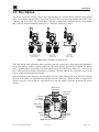
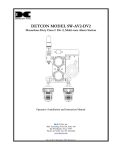
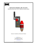
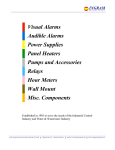
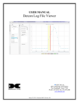
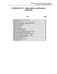
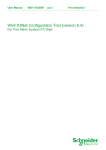
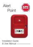
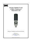
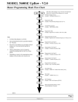
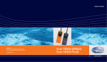
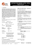
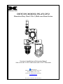
DETCON MODEL SW-AV1-DV2
Hazardous Duty Class I. Div 2, Multi-tone Alarm Station
Operator’s Installation and Instruction Manual
Also covers the V2-DV2 dual strobe and A1-DV2 Horn units
DETCON, Inc.
4500 Technology Forest Dr. Suite 100,
The Woodlands, Texas 77387
Ph.281.367.4100 / Fax 281.298.2868
www.detcon.com
Dec. 30, 2013 • Document # 3639 • Revision 0.4
SW-AV1-DV2
This page left intentionally blank
SW-AV1-DV2 Instruction Manual
ii
SW-AV1-DV2
Table of Contents
1.0
1.1
1.2
1.3
1.4
1.5
Description................................................................................................................................................ 1
Strobe ................................................................................................................................................... 2
Horn...................................................................................................................................................... 2
Smart Battery Pack............................................................................................................................... 3
Quad Battery Charger (Optional) ......................................................................................................... 3
RXT Series Wireless Transceivers....................................................................................................... 4
2.0
Installation................................................................................................................................................ 5
3.0
Operation.................................................................................................................................................. 6
4.0
Parts List................................................................................................................................................... 8
5.0
Warranty .................................................................................................................................................. 8
6.0
Revision Log ............................................................................................................................................. 8
Table of Figures
Figure 1 Basic C1D2 Wireless Alarm Stations .................................................................................................... 1
Figure 2 Wireless Interconnect PCA.................................................................................................................... 1
Figure 3 Strobe ..................................................................................................................................................... 2
Figure 4 Horn ....................................................................................................................................................... 2
Figure 5 Smart Battery Pack ............................................................................................................................... 3
Figure 6 Quad Battery Charger ............................................................................................................................ 4
Figure 7 Dimensional ........................................................................................................................................... 5
SW-AV1-DV2 Instruction Manual
iii
SW-AV1-DV2
This page left intentionally blank
Shipping Address: 4055 Technology Forest, Suite 100, The Woodlands, Texas 77381
Mailing Address: P.O. Box 8067, The Woodlands Texas 77387-8067
Phone: 888.367.4286, 281.367.4100 • Fax: 281.292.2860 • www.detcon.com • [email protected]
SW-AV1-DV2 Instruction Manual
iv
SW-AV1-DV2
1.0 Description
The Detcon AV1-DV2, V2-DV2, and A1-DV2 Alarm Stations are wireless, battery powered alarm stations
with a 5 Joule Strobe and an 115Db @ 1mtr Horn. The AV1-DV2 uses a Horn and a Strobe, the V2-DV2 uses
2 Strobes, and the A1-DV2 uses a single Horn. The unit is designed for installation and use in Hazardous
duty, corrosive work environments rated at Class 1, Division 2, Groups E, F, and G.
AV1-DV2
Strobe Horn Combo
Alarm Station
V2-DV2
Dual Strobe
Alarm Station
A1-DV2
Horn Only
Alarm Station
Figure 1 Basic C1D2 Wireless Alarm Stations
The alarm station can be positioned almost anywhere, since the wireless ability of the unit means that there is
no need for running conduit or outside connections. The alarm station is powered by its internal 12V battery
pack. Communication is performed via the Detcon RXT-300 or RXT-320 series of transceivers. Access to the
unit is only necessary for battery maintenance or exchange. With the addition of a solar panel, access can be
kept to periodic functional tests and checks.
Internal wiring between components runs through the Wireless Alarm Interconnect PCA. This PCA controls
the state of the alarms via communication with the Wireless Transceiver. When an alarm is triggered, the
wireless transceiver will provide the interconnect PCA with the signal(s) necessary to activate the proper
alarm(s).
wiring to/from
Transciever
wiring to/from
Transciever
External
24VDC
connections
7 89
Rotary Switch
for Modbus
Address
456
CD
AB E
23
F0 1
Alarm 2
wiring
Alarm 1
wiring
Figure 2 Wireless Interconnect PCA
SW-AV1-DV2 Instruction Manual
Rev. 0.4
Page 1 of 8
SW-AV1-DV2
If the unit uses the RXT-320 Transceiver, the rotary switch on the Wireless Alarm Interconnect PCA is used to
set the Modbus Address of the alarm unit. If more than one alarm station used in the system, each alarm
station must have a unique address for the alarm station to be recognized on the network properly. This switch
is not used with the RXT-300 Transceivers.
1.1 Strobe
The alarm station warning light is configured with choice of dome colors such as amber, blue, clear, green,
magenta, or red. Dome guard is included. The rugged warning light is specifically designed for hazardous
locations or corrosive environments where a very bright visual signal is required.
Figure 3 Strobe
1.2 Horn
The alarm station vibrating horn produces a noise level of a 115dB of sound by the electromechanical
vibration of a stainless steel diaphragm. The horn mechanism has an effective broadcast range of 200 feet.
The flamepath(s), flare and the body, are manufactured completely from UV stable glass reinforced polyester.
Stainless steel screws and sinter are incorporated thus ensuring a corrosion free product.
The horn is capable of producing coded blasts or sustained tones, and is excellent for general alarm,
start/dismissal, coded paging, and process control signaling in areas where their sound output exceeds ambient
noise levels. The horn in the Strobe/Horn alarm stations has 16 possible combinations of sounds that are
selectable by switch settings inside the alarm.
Figure 4 Horn
SW-AV1-DV2 Instruction Manual
Rev.0.4
Page 2 of 8
SW-AV1-DV2
1.3 Smart Battery Pack
Figure 5 Smart Battery Pack
The Wireless Alarm Station assembly also comes with a battery pack that allows the assembly to be remotely
mounted without the need for any cables because of its wireless operation. Detcon has several options for
battery packs. The battery packs provided are Detcon’s plug-in Smart Battery Packs which provides an output
of 12VDC (See Figure 5). The battery packs consist of rechargeable Lithium-Ion batteries and are equipped
with integrated safety electronics that include fuel gauge, voltage, current and temperature monitoring
circuits. This “smart” circuitry continuously monitors the battery’s condition and reports critical status
information to the wireless transceiver. The battery packs are designed to plug onto an 8-pin Beau connector
on the terminal board and should not be exposed to outside elements without being housed and protected.
Only Detcon products specifically designed to utilize these battery packs should be used. Operating periods
before recharge for the Wireless DM-100 assembly can be as long as 2-3 months and battery life can be up to
5 years before battery pack replacement is required. Improper use of the battery pack may be hazardous to
personnel or the environment and will void the warranty.
NOTE: The Wireless Alarm Station can also be powered by a customer provided external DC
power source. Refer to Section 2 for more details.
1.4 Quad Battery Charger (Optional)
Detcon’s Smart Battery Pack can be charged as needed using Detcon’s optional Quad Battery Charger which
can charge up to four battery packs at one time. The Quad Battery Charger comes with a plug-in AC/DC
adapter that plugs into a standard 120VAC outlet for power. The DC end of the adapter plugs into the DC
power jack of the charger providing 24VDC. The Quad Battery Charger has four charging ports, each with 8pin Beau connectors for battery pack connection. The ports and connectors are keyed to prevent incorrect
positioning and connection. Each port has its own “FAULT” LED indicator and “CHARGE” LED indicator
and will display either a red light or green light depending on the status of each battery being charged.
Charging times will vary depending on the charge state of each battery pack, but a full charge of a depleted
battery pack can take up to 24 hours.
SW-AV1-DV2 Instruction Manual
Rev. 0.4
Page 3 of 8
SW-AV1-DV2
Figure 6 Quad Battery Charger
When first powered on and with no battery packs connected to the charger, all the LED indicators on the Quad
Charger should be green. When a battery pack is seated into a charging port, the “CHARGE” LED will go
from green to red indicating the battery pack is not sufficiently charged. Once fully charged, the LED will go
from red to green and the battery pack is ready to be used.
The “Fault” LED should remain green indicating that there are no problems with the battery pack or charging
port. If the “Fault” LED turns red with the battery pack connected, then there is a problem or issue with the
battery pack and it should not be used and be removed immediately. If the “Fault” LED turns red without a
battery pack connected to the charge port, then there is a problem or issue with the port and that port should no
longer be used.
Battery packs can remain connected to the charger even after a full charge indication (Green “Charge” LED) is
shown due to the protection circuitry of the batter pack which prevents any overcharging issues.
1.5 RXT Series Wireless Transceivers
The wireless function of the alarm station is made possible by Detcon’s RXT series wireless transceivers.
These transceivers transmit signal data such as analog 4-20mA DC or serial Modbus™ and can support up to
32 devices. They operate at 2.4GHz and conform to non-licensed radio frequency appliance usage around the
world. Wireless network integrity and security is accomplished using direct sequence spread spectrum
wireless mesh technology. Wireless applications can be as simple as a single field device communicating with
a host controller or any number of field devices forming a network of subscribers. Every device in the
network is capable of functioning as a router and repeater for all other devices in the network. This means that
subscribers can “hop” through neighboring devices to communicate with each other thereby widening network
access points. This unique and innovative technology is designed to create a robust network that automatically
routes around congestion and line-of-sight obstacles while improving throughput as subscriber device density
increases.
Detcon offers two models of the wireless transceiver, Model RXT-300 and Model RXT-320. Both models are
functionally similar with one major difference: the RXT-300 provides a network wide control processing
capability, whereas the RXT-320 does not. Refer to each models instruction manual for more detailed
information.
SW-AV1-DV2 Instruction Manual
Rev.0.4
Page 4 of 8
SW-AV1-DV2
2.0 Installation
NOTE: The wireless alarm station is a precision instrument and care should be taken when handling it.
The Wireless AV1-DV2 Alarm Station is made to be mounted on a 2” or 3” diameter pipe. Two 3” U-bolts
with hardware are provided for mounting. The location for mounting the wireless alarm station should be
carefully selected. Occasional access to the unit will be necessary for battery replacement and maintenance.
No wiring is necessary for these units, once the unit has been mounted, install the battery pack and the unit
will begin normal operation.
6.5"
3.5"
2each U-Bolts and
hardware for mounting
0n 2"~3" Pole.
M ounting
U-Bolts
7.6"
31"
Typ.
16.1" Typ
12.3" Typ
Figure 7 Dimensional
If the unit is equipped with the RXT-320 Transceiver, the Address Switch on the Wireless Interconnect PCA
should be set to the correct address for the alarm station. This switch is normally set at the factory. If there is
more than one alarm station, each station should have a unique address for proper operation. For more
information refer to the RXT-320 manual. Units equipped with RXT-300 Transceiver do not use this switch.
To install the battery pack, insure that the area is de-classified. Remove the cover from the junction box.
Remove the Battery Cap, and install the battery. The battery can only be installed one way, and orientation is
mandated by the battery supports and the connector. Insure that the battery is completely seated, and close the
retaining lever over the battery until it latches. The unit will power up, and begin normal operation. Replace
the cover on the junction Box, and insure that the cover is completely screwed down and secured by the caphead screw.
Battery operation can be supplemented by the addition of an external 24VDC power source. The unit should
not need the addition of an external 24VDC power source, but if an external 24VDC is to be added, J6 is
provided for connection to the 24Volt input (refer to Figure 8 Typical Unit Wiring). This voltage will be used
to charge the battery pack as well as aid in operation of the alarm station.
SW-AV1-DV2 Instruction Manual
Rev. 0.4
Page 5 of 8
SW-AV1-DV2
Wireless
Transceiver
White/Violet
White/Green
White/Blue
Red
Black
Brown
Orange
White/Brown
White/Black
External 24VDC (+)
24VDC 24V Return (-)
Input
Green/Yellow
Green
DB3 PCA
Alarm Term Bd.
Red
Black
Green
Red
Black
Gnd
Strobe
Figure 8 Typical Unit Wiring
3.0 Operation
The Wireless C1D2 Alarm Stations provide a strobe and a horn, two strobes, or a single horn. The wireless
alarm station is set to respond to alarms from the controlling unit. The controller/wireless network has
independent control over the strobe and the Horn, and they will be activated when the appropriate alarm is
activated.
All strobes have a flash rate of 1 Hz (one flash per second). This is preset by the manufacture and cannot be
modified.
The horn has up to 32 possible settings, for use in different configurations. The default setting of the horn is
factory set. To change the setting of the horn, remove the rear end of the horn, and set dip switches according
to the Sound Signals Table.
SW-AV1-DV2 Instruction Manual
Rev.0.4
Page 6 of 8
SW-AV1-DV2
Table 1 Sound Signals
1
2
3
4
5
6
TONE FREQ/DESCRIPTION
Alt Tones 800/970 Hz at 1/4 sec
Sweeping 800/970 Hz at 7Hz
Sweeping 800/1000 Hz at 1 Hz
Continuous at 2850 Hz
Sweeping 2400-2850 Hz at 7 Hz
Sweeping 2400-2850 Hz at 1 Hz
7
Slow Whoop
8
Sweep 1200-500 Hz at 1 Hz
9
Alt. Tones 2400/2850 Hz at 2 Hz
10
Int. Tone of 970 Hz at 1 Hz
11
Alt. Tones 800/970 Hz at 7/8 Hz
12
Int. Tone at 2850 Hz at 1Hz
13
970Hz at 1/4 sec on 1 sec off
14
Continuous at 970 Hz
15 554Hz for 100ms / 440 Hz for 400ms
16
Int. 660 Hz 150 ms on 150 ms off
17
Int. 660 Hz 1.8 sec on 1.8 sec off
18
Int. 660 Hz 6.5 sec on 13 sec off
19
Continuous 660 Hz
20
Alt 554/440 Hz at 1 Hz
21
Int. 660 Hz at 7/8 Hz
22
Int. 2850 Hz 150 ms on 100 ms off
23
Sweep 800-970 Hz at 50 Hz
24
Sweep 2400-2850 Hz at 50 Hz
25 3 970Hz pulses 0.5on/0.5off, 1.5 off
26 3 2850Hz pulses 0.5on/0.5off, 1.5 off
27
Int. 3100 Hz 0.32s on / 0.68s off
28
Spare/Customer Tone
29
Spare/Customer Tone
30
Spare/Customer Tone
31
Spare/Customer Tone
32
Spare/Customer Tone
SW-AV1-DV2 Instruction Manual
Rev. 0.4
SWITCH
11111
11110
11101
11100
11011
11010
11001
11000
10111
10110
10101
10100
10011
10010
10001
10000
01111
01110
01101
01100
01011
01010
01001
01000
00111
00110
00101
00100
00011
00010
00001
00000
TONE
Fast Sweep(LF)
Med Sweep(LF)
Fast Sweep
Slow Whoop
Din Tone
Back-Up Alarm(LF)
Back Up Alarm(HF)
French Fire Sound
Swedish Fire Alarm
Swedish Fire Alarm
Swedish Fire Alarm
Swedish Fire Alarm
Swedish Fire Alarm
Swedish Fire Alarm
Pelican Crossing
Low Freq. Buzz
High Freq. Buzz
Page 7 of 8
SW-AV1-DV2
4.0 Parts List
Detcon Part #
Description
354-1916x6-024
24VDC Strobe, Ext Ground (x represents color of lamp)
Strobe colors: Red (2), Amber (4), Green (5), Blue (6), Magenta (7), and Clear (9)
Model DB3 Horn
24V Wireless Alarm Interconnect PCA
RXT-300 Wireless Transceiver
RXT-320 Wireless Transceiver
12VDC, 2200mAh Battery Pack
12VDC, 2900mAh Battery Pack
356-DB3007-024
500-005146-100
976-000300-316
976-000320-316
976-0BP303-012
976-0BP303-290
5.0 Specifications
Strobe
Dome Colors
Flash Rate/Minute
Lamp Source
Amber / Blue / Clear / Green / Magenta / Red
60
LED
Db Output
Duty Cycle
115db @ 1meter (tone dependent)
Not rated for continuous duty (5 minute duty cycle)
Operating Current
Operating Temperature
Voltage
Dimensions
2.8A Max (both Horn and Strobe operational)
-20ºC to 60ºC
12VDC
29.5”H X 14.75”W X 13”D AV1 – Strobe / Horn Units
29.5”H X 15”W X 13”D
V2 – Dual Strobe Units
28.5”H X 14.65”W X 13”D A1 – Horn Only Units
Horn
Alarm Unit
6.0 Warranty
Detcon Inc., as manufacturer, warrants under intended normal use each new SW-AV1-DV2, SW-A1-DV2, and
SW-V1-DV2 Alarm station to be free from defects in material and workmanship for a period of one year. The
warranty period begins from the date of shipment to the original purchaser and ends one year thereafter. All
warranties and service policies are FOB the Detcon Inc. facility located in The Woodlands, Texas.
7.0 Revision Log
Revision
0.0
0.1
0.2
0.3
0.4
Date
02/10/11
04/27/11
11/30/11
08/08/13
12/30/13
Changes made
Initial Release
Combined Specifications Table, Updated Spare Parts List
Updated Mounting Plate
Update for new battery pack, new unit build, new PCA
Corrections to Horn and other information
Approval
LU
LU
LU
LU
LU
Shipping Address: 4055 Technology Forest, Suite 100, The Woodlands, Texas 77381
Mailing Address: P.O. Box 8067, The Woodlands Texas 77387-8067
Phone: 888.367.4286, 281.367.4100 • Fax: 281.292.2860 • www.detcon.com • [email protected]
SW-AV1-DV2 Instruction Manual
Rev.0.4
Page 8 of 8