1
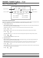
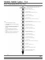
MODEL 5600SE Upflow - V2.0
Master Programming Mode Flow Chart
With Time of Day Display set to 12:01 P.M., Push and hold
both the Set Up and Set Down Buttons for 5 seconds.
US/Metric Display Format
Example: US Display Format [U--1]
Regeneration Type
Example: Metered Delayed Regeneration [7--3]
Treated Water Capacity
Example: 1,000 Gallons [1000]
Regeneration Time
Example: Regenerate as needed at 2:00 A.M. [2:00]
Regeneration Day Override
Example: Regenerate at a minimum frequency of 3 days [A--3]
Note:
1.
Set Time of Day Display to 12:01 P.M.
2.
Push and hold both the Set Up and Down Buttons
for 5 Seconds.
3.
Push Extra Cycle Button once per display until all
displays are viewed and normal operation is
resumed.
4.
Option setting displays may be changed as
required by pushing either the Set Up or Down
Button.
5.
Depending on current valve programming certain
displays will not be able to be viewed or set.
Regeneration Cycle Step #1
Example: 10 minute step time [1-10]
Regeneration Cycle Step #2
Example: 60 minute step time [2-60]
Regeneration Cycle Step #3
Example: 10 minute step time [3-10]
Regeneration Cycle Step #4
Example: 12 minute step time [4-12]
Regeneration Cycle Step #5
Example: Step 5 Cancelled [5OFF]
Flow Meter Size
Example: 5600SE 3/4″ Turbine Flow Meter [F133]
Valve Type
Example: 5600SE Valve [o--1]
Line Frequency
Example: 60Hz Line Frequency [LF60]
Master Programming Mode is exited.
Normal Operation is resumed.
Page 1
Printed in U.S.A.
MODEL 5600SE Upflow - V2.0
Master Programming Mode
Program Indicator
Service
Flow
Program
P.M.
Set Up Button
Set Down Button
Extra Cycle Button
Regeneration Display
Step 1 - Brine/Rinse
Step 3 - Rapid Rinse
Step 2 - Backwash
Step 4 - Brine Refill
Entering Master Programming Mode
With Time of Day Display set to 1201 PM, push and hold for 5 seconds both the Set Up and Down Buttons. The Program Indicator
will turn on to signal that this mode is entered. In this mode all possible option settings may be viewed.
1.
US/Metric Display Format (U)
Depress the Extra Cycle Button. This display is used to set the desired display format. This option setting is identified by the
letter U in the first digit. There are two possible settings:
US Format uses gallons for volume with a 12 hour timekeeping format. Regeneration timing in minutes.
Example -
[
]
Metric Format uses liters for volume with a 24 hour timekeeping format. Regeneration timing in tenths of minutes.
Example -
[
]
Cubic Meter Format uses m3 for volume with a 24 hour timekeeping format. Regeneration timing in tenths of minutes.
Example -
[
]
The Set UP and DOWN Buttons will adjust this value.
2.
Regeneration Type (7)
Depress the Extra Cycle Button. This display is used to set the Regeneration Type. This option setting is identified by the
number 7 in the first digit. There are 3 possible settings:
Timeclock Delayed. The control will determine that regeneration is required when the set Regeneration Time has been
reached. The Regeneration Day Override setting will determine which days a regeneration cycle will be initiated.
Example -
[
]
Meter Immediate. The control will determine that regeneration is required when the available volume of softened water drops
to or below zero. Regeneration to begin immediately.
Example -
[
]
Page 2
Printed in U.S.A.
MODEL 5600SE Upflow - V2.0
Master Programming Mode (Cont’d.)
2.
Regeneration Type (7) (Cont’d.)
Meter Delayed. The control will determine that a regeneration is required when the available volume of softened water drops
to or below zero. Regeneration is to begin immediately at the set Regeneration Time.
Example -
[
]
The Set UP and DOWN Buttons will adjust this value.
3.
Treated Water Capacity (No Display Code)
Depress the Extra Cycle Button. This display is used to set the amount of treated water (gallons/liters) that can be produced by
the unit before a regeneration cycle is required. With Meter Delayed Regeneration Type set, it will be up to the programmer to
determine a reserve capacity and subtract that value from the calculated full capacity of the unit. This display will not be
viewed with Timeclock Regeneration Type set.
Example: Regenerate every 700 gallons, liters, or m3 -
[
]
The Set UP and DOWN Buttons will adjust this value.
4.
Regeneration Time (No display Code)
Depress the Extra Cycle Button. The next display viewed is the option setting for Regeneration Time. It is identified by a nonflashing colon between two sets of numbers. Set the desired time of day that a regeneration may occur, if required. This display
will not be viewed with Meter Immediate Regeneration Type set.
Example: 2 o’clock A.M. regeneration time -
[
]
(A.M. Indicator Dot On)
The Set UP and DOWN Buttons will adjust this value.
5.
Regeneration Day Override (A)
Depress the Extra Cycle Button. This display is used to set the maximum amount of time (in days) the unit can be in service
without a regeneration. This option setting is identified by the letter ‘A’ in the first digit. With Meter Immediate Regeneration
Type selected, regeneration will begin at the same point in time some amount of days ago when the last regeneration cycle was
initiated. With Timeclock or Meter Delayed Regeneration Types selected, regeneration begins at the set Regeneration Time.
An OFF setting will cancel this feature with all regeneration types except Timeclock Regeneration were it must be used.
Examples: Override every 7 days Cancel setting -
[
[
]
] (Meter Immediate or Delayed Regeneration Types Only)
The Set UP and DOWN Buttons will adjust this value.
6.
Regeneration Cycle Step Programming (1) (2) (3) (4) (5) (6)
Depress the Extra Cycle Button. The next 2-4 displays viewed are part of a series of option settings used to program the
Regeneration Cycle. Up to 4 steps can be programmed. Each display is used to set the duration time in minutes (or tenths of
minutes - Metric) of that specific step in a regeneration cycle. A step # will turn on for the regeneration cycle step being
programmed. Regeneration steps are skipped by setting the display to 0 and regeneration ended by setting the step # after the
last active step to OFF, as shown below and on the next page:
Examples: Regeneration Cycle Step #1 - 8 minutes Regeneration Cycle Step #3 - skipped
-
[
[
]
]
Page 3
Printed in U.S.A.
MODEL 5600SE Upflow - V2.0
Master Programming Mode (Cont’d.)
6.
Regeneration Cycle Step Programming (1) (2) (3) (4) (5) (6) (Cont’d.)
Examples: Regeneration Cycle Step #4 - cancelled
-
Regeneration Cycle Step #4 - 8.5 minutes -
[
[
]
]
(Metric Format)
Depress the Extra Cycle Button once per display to advance through Regeneration Cycle Step Programming.
The 5600SE control has a separate brine tank fill cycle. Your desired salt setting must be calculated, using the blue (.25 gpm)
or black (.5 gpm) rate of refill (in gpm) times your timer setting. Then using one gallon of fresh water dissolving
approximately 3 lbs. of salt, calculate your refill time.
Example:
lbs. salt 3 ÷ B.L.F.C. Size = refill time in minutes, 10 lbs. salt ÷ 3 ÷ .25 = 13.3 minute refill
The Set UP and DOWN Buttons will adjust these values.
7.
Flow Meter Size (F)
Depress the Extra Cycle Button. The next display is used to set the flowmeter size. This option setting is identified by the letter
F in the first digit. In this display set the proper amount of pulses generated by the flow meter for each gallon or liter of water
flow. This setting will not be viewed with Timeclock Regeneration Type selected.
Examples -
[
[
]
]
3/4″ Turbine Flow Meter (US Format)
3/4″ Turbine Flow Meter (Metric Format)
The Set UP and DOWN Buttons will adjust this value.
8.
Valve Type (o)
Depress the Extra Cycle Button. This display is used to set the type of valve used with the control. This option setting is
identified by the letter o in the first digit. There are two possible selections with #1 being the required setting:
Examples -
[
[
]
]
5600SE Valve Operation.
Option Not Typically Used.
The Set UP and DOWN Buttons will adjust this value.
9.
Line Frequency (LF)
Depress the Extra Cycle Button. This display is used to set the frequency of the power applied to the control. When properly
set, all timekeeping functions will remain accurate. This option setting is identified by the letter o in the first digit. There are
two possible selections.
Examples -
[
[
]
]
50Hz Line Frequency Operation.
60Hz Line Frequency Operation.
The Set UP and DOWN Buttons will adjust this value.
Exiting This Option Setting Level
Push the Extra Cycle Button once per display until all have been viewed. The Program Mode will be exited and normal operation
resumed.
Resetting Permanent Programming Memory Push and hold the Set Up and Down Buttons for 25 seconds or until the Time Of Day Display resets to 12:00 P.M. All option
settings will then reset to default values. Control programming will then have to be reset as necessary.
Page 4
P/N 41675
Printed in U.S.A.
Rev. A