1
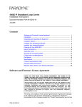
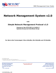
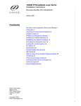
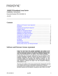
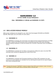
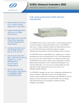
Interface Module User Guide
AIM24000-48
and
AIM24000-48B
48-Port ADSL2+ Inverse Multiplexers
© Copyright 2004 Net to Net Technologies, Inc.
™ The Net to Net Logo is a trademark of Net to Net Technologies, Inc.
Worldwide Headquarters
Net to Net Technologies
112 Corporate Drive
Portsmouth, NH 03801 USA
1 (877) 638-2638
[email protected]
AIM24000 Installation 210-0000056 rev 01
http://www.nettonet.com
EMEA Headquarters
Net to Net Technologies
Victoria House, 19 Park Way
Newbury Berkshire RG14 1EE UK
44 (0) 1635-570950
[email protected]
Page 1 of 44
Contents
1.0 ADSL2+ INVERSE MULTIPLEXER MODEL TYPES
1.1 AIM24000-48
1.2 AIM24000-48B
2.0 INSTALLATION
2.1 Unpack and Inspect the AIM24000
2.2 Install the AIM24000 in an IP DSLAM
2.2.1 12-Slot IP DSLAM
2.2.1.1
2.2.1.2
2.2.1.3
2.2.1.4
Select a Slot for Installation
Align the AIM24000 with the Slot Module Guides
Slide the AIM24000 Firmly into the Chassis
Secure the AIM24000 in the Chassis
2.2.2.1
2.2.2.2
2.2.2.3
2.2.2.4
Select a Slot for Installation
Align the AIM24000 with the Slot Module Guides
Slide the AIM24000 Firmly into the Chassis
Secure the AIM24000 in the Chassis
2.2.2 4-Slot IP DSLAM
2.3 Verify Power Reception
2.4 Connect Your ADSL Cable(s)
2.4.1 Local Connection
2.4.1.1 12-Slot IP DSLAM
2.4.1.2 4-Slot IP DSLAM
2.4.2 Remote Connection
2.4.3 ADSL RJ21 Pinout
2.5 Verify the ADSL Connection(s)
3.0 ADSL Parameters
3.1 Default Configurations
3.2 Parameter Definitions
3.2.1 Circuit ID
3.2.2 Standard Mode
3.2.2.1
3.2.2.2
3.2.2.3
3.2.2.4
Multimode
Full Rate ADSL2
Full Rate ADSL
G.lite
3.2.3.1
3.2.3.2
3.2.3.3
3.2.3.4
Adaptive
Fixed
Fixed Adaptive
Off
3.2.3 Port Mode
3.2.4 Bandwidth and Distance
3.2.4.1 Full Rate ADSL2
3.2.4.2 Full Rate ADSL
3.2.4.3 G.lite
3.2.5 IP Range
3.2.6
3.2.7
3.2.8
3.2.9
3.2.5.1 Single IP Address
3.2.5.2 IP Address Range
3.2.5.3 Full IP Address Range
VLAN
Backbone-VLAN
VLAN Priority
Protocol
3.2.9.1 All
3.2.9.2 Select
AIM24000 Installation 210-0000056 rev 01
Page 2 of 44
3.2.10 Flood
3.2.10.1 Uplink
3.2.10.2 VLAN
3.2.11 Frame Type
3.2.11.1 1438LLC
3.2.11.2 1483VCM
3.2.12 VPI/VCI Detect
3.2.12.1 On
3.2.12.2 Off
3.2.12.3 Manual
4.0 AIM24000 Management
4.1 Via NMS
4.1.1 Log In
4.1.2 Circuit Configuration
4.1.2.1 Verify Port Information
4.1.2.2 Circuit Identification
4.1.2.3 Port Mode
4.1.2.4 VPI/VCI Detect
4.1.2.5 IP Range
4.1.2.6 Protocol
4.1.2.7 DHCP Option 82
4.1.2.8 Layer 2 Port Filters
4.1.2.9 Frame Type
4.1.2.10 Standard Mode
4.1.2.11 Submit
4.1.3 VLAN Rules
4.2 Via CLI
4.2.1 Log In
4.2.2 Circuit Configuration
4.2.2.1 Circuit Identification
4.2.2.2 Standard Mode
4.2.2.3 Port Mode
4.2.2.4 Speed
4.2.2.5 IP Range
4.2.2.6 VLAN Range
4.2.2.7 Backbone-VLAN
4.2.2.8 VLAN Priority
4.2.2.9 Protocol
4.2.2.10 Flood
4.2.2.11 Frame Type
4.2.2.12 VPI/VCI Detect
4.3 Via SNMP
4.3.1 Contact your IP DSLAM
4.3.2 Circuit Configuration
5.0 ADDITIONAL INFORMATION
5.1 LED Indications
5.2 DATA STORAGE
5.2.1 Memory
5.2.1.1 RAM
5.2.1.2 NVRAM
5.2.2 Local Files
5.2.2.1 Uploading a Port Template
5.2.2.2 Downloading a Port Template
5.3 Firmware Upgrades
5.4 Regulatory Compliance for Class A Equipment
AIM24000 Installation 210-0000056 rev 01
Page 3 of 44
1.0 ADSL2+ INVERSE MULTIPLEXER MODEL TYPES
1.1 AIM24000-48
The AIM24000-48 is a 48-port ADSL2+ inverse multiplexer that supports Annex A (Plain
Old Telephone Service-POTS) on lower end frequencies (up to 4 kHz).
1.2 AIM24000-48B
The AIM24000-48B is a 48-port ADSL2+ inverse multiplexer that supports Annex B
(Integrated Services Digital Network-ISDN) on lower end frequencies: up to 80 kHz over a
Two Binary, One Quaternary (2B1Q) line and up to 100 kHz over a Four Binary, Three
Ternary (4B3T) line.
2.0 INSTALLATION
CAUTION Net to Net Technologies strongly recommends the use of proper electrostatic discharge (ESD) precautions when handling this
equipment.
2.1 Unpack and Inspect the AIM24000
AIM24000 SPECIFICATIONS
12.75" High x 1.15" Wide x 16.75" Deep
(32.4cm x 2.9cm x 42.5cm)
3.6 lbs (1.6 kg)
If there is visible damage, do not attempt to connect the device. Contact Customer
Support: customers in Europe, the Middle East and Africa please call 44-0-1635-570953 or
email [email protected] ; customers in the United States please call 1-877-6382638 or email [email protected]. All other customers please call 1-603-427-0600 or
email [email protected].
2.2 Install the AIM24000 in an IP DSLAM
There must be a management module, complete with an uplink module, installed in your
IP DSLAM chassis in order for the AIM24000 to operate.
NOTE All of Net to Net Technologies' IP DSLAM interface modules are hot swappable; installing or removing an interface module
while the chassis is powered up does not affect the operational status of other interface modules within the chassis.
AIM24000 OPERATING REQUIREMENTS
Operating Temperature:
32°F to 122°F (0°C to 50°C) in an IPD12000E
-40°F to 149°F (-40°C to 65°C) in an IPD4000E
Non-Operating Temperature: -40°F to 158°F (-40°C to 70°C)
Humidity: 5% to 95%, non-condensing
Altitude: -200 ft to 16,500ft (-60m to 5,000m)
AIM24000 Installation 210-0000056 rev 01
Page 4 of 44
2.2.1 12-Slot IP DSLAM
The IPD12000 and IPD12000E are fourteen [14] slot chassis; slots 1-12 are reserved
for interface modules (such as the AIM24000) and slots U1 and U2 are reserved for
management modules.
NOTE Although the AIM24000 can be installed in both the IPD12000 and the IPD12000E, the IPD12000 has the
capability to support AIM24000 ports 1-24 only; in order to make use of all 48 ports, you must install the
AIM24000 in an IPD12000E.
2.2.1.1 Select a Slot for Installation
The AIM24000 may be placed in any slot, 1-12. Remove the blank plate from the
chosen slot by turning the fastening screws counter-clockwise with a screwdriver
and then gently sliding the blank plate out of the chassis.
12-SLOT IP DSLAM
FASTENING SCREW
(turn counter-clockwise
to loosen)
Blankplate Fastening Screws
Empty Interface Module Slot
AIM24000 Installation 210-0000056 rev 01
Page 5 of 44
CAUTION If a blank plate is removed from slot 1-12 on Net to Net's IPD12000 or IPD12000E, it must be replaced
with an interface module. DO NOT OPERATE YOUR IP DSLAM WITH AN EMPTY SLOT.
2.2.1.2 Align the AIM24000 with the Slot Module Guides
With the AIM24000 Printed Circuit Board (PCB) facing RIGHT and the AIM24000
model name, and Net to Net logo, on the LOWER edge of the faceplate, align the
upper and lower edges of the PCB with the slot module guides.
AIM24000
Slot Module Guides
2.2.1.3 Slide the AIM24000 Firmly into the Chassis
DO NOT USE EXCESS FORCE.
2.2.1.4 Secure the AIM24000 in the Chassis
Tighten the fastening screws on the AIM24000 faceplate by turning them
clockwise with a screwdriver, just until snug. DO NOT OVER-TIGHTEN the
fastening screws.
AIM24000 Installation 210-0000056 rev 01
Page 6 of 44
FASTENING SCREW
(turn clockwise
to tighten)
AIM24000 Fastening Screws
2.2.2 4-Slot IP DSLAM
The IPD4000 and IPD4000E are five [5] slot chassis, slots 1-4 are reserved for
interface modules (such as the AIM24000) and slot U1 is reserved for a management
module.
NOTE Although the AIM24000 can be installed in both the IPD4000 and the IPD4000E, the IPD4000 has the capability to
support AIM24000 ports 1-24 only; in order to make use of all 48 ports, you must install the AIM24000 in an
IPD4000E.
2.2.2.1 Select a Slot for Installation
The AIM24000 may be placed in any slot, 1-4. Remove the blank plate from the
chosen slot by turning the fastening screws counter-clockwise with a Phillips
screwdriver and then gently sliding the blank plate out of the chassis
FASTENING SCREW
4-SLOT IP DSLAM
Blankplate
Fastening
Screws
(turn counter-clockwise
to loosen)
Empty
Interface
Module Slot
CAUTION If a blank plate is removed from slot 1-4 on Net to Net's IPD4000 or IPD4000E, it must be replaced with
an interface module. DO NOT OPERATE YOUR IP DSLAM WITH AN EMPTY SLOT.
AIM24000 Installation 210-0000056 rev 01
Page 7 of 44
2.2.2.2 Align the AIM24000 with the Slot Module Guides
With the AIM24000 Printed Circuit Board (PCB) facing UP and the AIM24000
faceplate model name, and Net to Net logo, on the RIGHT, align the edges of the
PCB with the slot module guides on both sides.
4-SLOT IP DSLAM
AIM24000
Slot Module Guides
2.2.2.3 Slide the AIM24000 Firmly into the Chassis
DO NOT USE EXCESS FORCE.
2.2.2.4 Secure the AIM24000 in the Chassis
Tighten the fastening screws on the AIM24000 faceplate by turning them
clockwise with a Phillips screwdriver, just until snug. DO NOT OVER-TIGHTEN the
fastening screws.
FASTENING SCREW
AIM24000
Fastening
Screws
(turn clockwise
to tighten)
2.3 Verify Power Reception
NOTE If you have not already powered up your IP DSLAM, do so now. Refer to your IP DSLAM Installation Instructions at
http://www.nettonet.com/support/docs/#i for further instruction.
POWER SPECIFICATIONS
-48V DC (supplied by the host IP DSLAM)
1.6 Amps
The PWR (power) LED on the AIM24000 faceplate will illuminate solid green to indicate the
AIM24000 is receiving power.
AIM24000 Installation 210-0000056 rev 01
Page 8 of 44
2.4 Connect Your ADSL Cable(s)
2.4.1 Local Connection
2.4.1.1 12-Slot IP DSLAM
2.4.1.1.1 Identify the Correct RJ21 Port(s) for Connection
Subscriber lines must be connected according to the IP DSLAM slot in
which the AIM24000 was installed. Interface module slots 1-12 run from
left to right when you are facing the front of the chassis; the corresponding
RJ21 ports are directly behind each slot on the back of the chassis (1-12,
right to left, when you are facing the back of the chassis). Each interface
module slot on Net to Net's IPD12000E has two [2] corresponding female
RJ21 connectors: the bottom row of connectors (A) provides the ADSL
connection for AIM24000 ports 1-24 and the top row of RJ21 connectors
(B) provides the ADSL connection for ports 25-48.
NOTE Net to Net's IPD12000 has only one female RJ21 connector for each interface module slot. These
connectors support ports 1-24 (only) on your AIM24000; ports 25-48 cannot be connected in an
IPD12000.
IPD12000E Rear View
In previous illustrations, the
AIM24000 was installed in Slot
3 of an IPD12000E and, as
such, the ADSL cable would
require connection to the
following RJ21 ports:
Female RJ21 Connector 3B
for AIM24000 ports 25-48
Female RJ21 Connector 3A
for AIM24000 ports 1-24
AIM24000 Installation 210-0000056 rev 01
Page 9 of 44
2.4.1.1.2 Connect Your ADSL Cable(s)
NOTE No configuration is necessary for the AIM24000 to operate at default settings. However, if you wish
to run your subscriber connections at settings other than the factory defaults, Net to Net
recommends configuring the AIM24000 prior to ADSL connection. Refer to Section 4.0 for further
information.
2.4.1.1.2.1 Detach the Velcro Strap
Detach the Velcro Strap from the female RJ21 connector port: lift the
Velcro tab on the left and pull the strap open towards the right,
leaving it looped under the right side of the connector frame.
FEMALE RJ21 CONNECTOR PORT
2.4.1.1.2.2 Position the RJ21 Connector
Slide the male RJ21 connector of your ADSL cable underneath the
Velcro, from the bottom, and press it firmly into the female RJ21
connector port on the chassis.
MALE RJ21 CONNECTOR OF
YOUR ADSL CABLE
2.4.1.1.3 Secure the Cable(s)
Pull the Velcro strap to the right, making sure that it is snug against the
connector, then pull the strap back towards the left, such that the Velcro
layers stick to one another across the top of the connector. Tuck the tab at
the end of the strap down to the left of the connector frame so that it is
out of the way of other connections. Screw the top of the RJ21 cable
connector into the jack screw at the top of the RJ21 connector frame on the
chassis.
AIM24000 Installation 210-0000056 rev 01
Page 10 of 44
NOTE If you are using a 120 or 180 degree cable, both the top and the bottom of the RJ21 cable
connector should be screwed to the connector frame on the chassis.
2.4.1.2 4-Slot IP DSLAM
2.4.1.2.1 Identify the Correct RJ21 Port(s) for Connection
Subscriber lines must be connected according to the IP DSLAM slot in
which the AIM24000 was installed. Interface module slots 1-4 run from
bottom to top on the front of the chassis; the corresponding RJ21 ports are
directly behind each slot on the back of the chassis (1-4, bottom to top).
Each interface module slot on Net to Net's IPD4000E has two [2]
corresponding female RJ21 connectors: the connectors on the left (A)
provide the ADSL connection for AIM24000 ports 1-24 and the connectors
on the right (B) provide the ADSL connection for AIM24000 ports 25-48.
NOTE Net to Net's IPD4000 has only one female RJ21 connector for each interface module slot. These
connectors support ports 1-24 (only) on your AIM24000; ports 25-48 cannot be connected in an
IPD4000.
IPD4000E Rear View
In previous illustrations,
the AIM24000 was
installed in Slot 3 of an
IPD4000E and, as such,
the ADSL cable would
require connection to
the following RJ21 ports:
Female RJ21
Connector 3A for
AIM24000 ports 1-24
Female RJ21
Connector 3B for
AIM24000 ports 25-48
2.4.1.2.2 Connect Your ADSL Cable(s)
NOTE No configuration is necessary for the AIM24000 to operate at default settings. However, if you wish
to run your subscriber connections at settings other than the factory defaults, Net to Net
recommends configuring the AIM24000 prior to connection. Refer to Section 4.0 for further
information.
2.4.1.2.2.1 Detach the Velcro Strap
Detach the Velcro Strap from the female RJ21 connector port: lift the
Velcro tab from the bottom and pull the strap open, towards the top
AIM24000 Installation 210-0000056 rev 01
Page 11 of 44
of the chassis, leaving it looped under the top side of the connector
frame.
FEMALE RJ21 CONNECTOR PORT
2.4.1.2.2.2 Position the RJ21 Connector
Slide the male RJ21 connector of your ADSL cable underneath the
Velcro, from the left, and press it firmly into the female RJ21
connector port on the chassis.
MALE RJ21 CONNECTOR OF YOUR ADSL CABLE
2.4.1.2.3 Secure the Cable(s)
Pull the Velcro strap upward, making sure that it is snug against the
connector, then pull the strap back down, such that the Velcro layers stick
to one another across the top of the connector. Tuck the tab at the end of
the strap down between the connector frames so that it is out of the way of
other connections and then screw the right side of the RJ21 cable
connector into the jack screw on the right side of the RJ21 connector frame
on the chassis.
NOTE If you are using a 120 or 180 degree cable, both the left and right sides of the RJ21 cable connector
should be screwed to the connector frame on the chassis.
AIM24000 Installation 210-0000056 rev 01
Page 12 of 44
2.4.2 Remote Connection
A single line connection can be established between any port on the AIM24000 and
any compatible G.lite, ADSL, ADSL2 or ADSL2+ modem.
2.4.3 ADSL RJ21 Pinout
PORT
AIM24000-48 ADSL FEMALE RJ21 CONNECTOR PORT
PIN
RING TIP
1
1
26
2
2
27
3
3
28
4
4
29
5
5
30
6
6
31
7
7
32
8
8
33
9
9
34
10
10
35
11
11
36
12
12
37
13
13
38
14
14
39
15
15
40
16
16
41
17
17
42
18
18
43
19
19
44
20
20
45
21
21
46
22
22
47
23
23
48
24
24
49
ADSL CABLE MALE RJ21 CONNECTOR
(Pins 25 and 50 are not used)
2.5 Verify the ADSL Connection(s)
The LK (Link) LED for each port being connected to a remote modem will illuminate solid
green to indicate a connection has been established. Link up time between the AIM24000
and remote modems can vary from one to five minutes depending on the quality, gauge
and distance of the copper cable pair(s) being used.
AIM24000 Installation 210-0000056 rev 01
Page 13 of 44
3.0 ADSL Parameters
3.1 Default Configurations
No configuration is necessary for the AIM24000 to operate at default settings.
PARAMETER
DEFAULT
Standard Mode
Multimode
Port Mode
Adaptive
Upstream Speed
n/a (Adaptive Port Mode)
Downstream Speed
n/a (Adaptive Port Mode)
IP Range 1
0.0.0.0 - 255.255.255.255
IP Range 2-4
0.0.0.0 - 0.0.0.0
VLAN
0-0
Backbone-VLAN
0
VLAN Priority
0
Protocol
All
Flood
Uplink
Frame Type
1483LLC
VPI/VCI Detect
On
Virtual Path Identifier (VPI)
0
Virtual Channel Identifier (VCI) 35
3.2 Parameter Definitions
3.2.1 Circuit ID
Circuit Identification (ID) is a unique and searchable 15-character, alpha-numberic,
user-defined identifier used to label each port. If the Circuit ID entered is longer than
AIM24000 Installation 210-0000056 rev 01
Page 14 of 44
15 characters, it will automatically truncate to 15. Typically, service providers use a
corresponding Customer # or Circuit ID # from their Operations Support System (OSS)
in order to facilitate troubleshooting.
NOTE Net to Net's Circuit ID field is not yet integrated with any OSS system and is currently for reference only.
3.2.2 Standard Mode
Default: Multimode
3.2.2.1 Multimode
An AIM24000 port set to multimode detects and matches the standard mode of
the remote ADSL modem to which it's connected.
3.2.2.2 Full Rate ADSL2
An AIM24000 port that is operating in full rate ADSL2 mode and utilizing a
single line for both phone and data, requires an in-line splitter at both ends of
the ADSL2 connection.
NOTE The Full Rate ADSL2 options (G.DMT.BIS, G.DMT.BISplus and READSL2) are not yet available for
configuration via CLI or SNMP; these standard modes are currently configurable via NMS only.
3.2.2.2.1 G.DMT.BIS
G.DMT.BIS is ADSL2 technology in compliance with the standards of the
International Telecommunications Union Telecommunication
Standardization Sector (ITU-T) Recommendation G.992.3 which specifies a
downstream frequency range of 1100 kHz.
3.2.2.2.2 G.DMT.BISplus
G.DMT.BISplus is ADSL2+ technology in compliance with the standards of
ITU-T Recommendation G.992.5 which specifies a downstream frequency
range of 2200 kHz.
3.2.2.2.3 READSL2
Reach Expanded ADSL2 is ADSL2 technology in compliance with the
standards of ITU-T Recommendation G.992.3 in Annex L format.
3.2.2.3 Full Rate ADSL
An AIM24000 port that is operating in full rate ADSL mode and utilizing a single
line for both phone and data, requires an in-line splitter at both ends of the
ADSL connection.
3.2.2.3.1 G.DMT
G.DMT is ADSL technology in compliance with the standards of ITU-T
Recommendation G.992.1. The AIM24000 exceeds the ITU-T G.992.1
minimum requirements of 640 kbps upstream and 6,000 kbps downstream
speeds in G.DMT mode.
3.2.2.3.2 T1.413
T1.413 is ADSL technology in compliance with the standards of the
American National Standards Institute (ANSI) Standard T1.413.
3.2.2.3.3 Alcatel
Alcatel is ADSL technology and Alcatel ADSL modem compatible.
AIM24000 Installation 210-0000056 rev 01
Page 15 of 44
3.2.2.4 G.lite
G.lite is ADSL technology in compliance with the standards of ITU-T
Recommendation G.992.2. The AIM24000 meets the ITU-T Recommendation
G992.2 minimum requirements of 512 kbps upstream and 5,136 kbps
downstream speeds in G.lite mode. An AIM24000 port that is operating in G.lite
mode and utilizing a single line for both phone and data, requires an in-line
splitter at the local end, and a microfilter at the remote end, of the ADSL
connection.
3.2.3 Port Mode
Default: Adaptive
3.2.3.1 Adaptive
An AIM24000 port set to port mode adaptive will automatically train up to the
best possible speed supported by the AIM24000, the ADSL modem at the
remote end, and the copper cable pair connecting the two.
3.2.3.2 Fixed
An AIM24000 port set to port mode fixed will maintain consistant upstream and
downstream bandwidths as specified by the user.
3.2.3.3 Fixed Adaptive
An AIM24000 port set to port mode fixed adaptive will automatically train up to
the best possible speed supported by the AIM24000, the ADSL modem at the
remote end, and the copper cable pair connecting the two, within the confines
of user-specified maximum upstream and downstream bandwidths.
3.2.3.4 Off
An AIM24000 port set to port mode off has been administratively turned off.
3.2.4 Bandwidth and Distance
The default bandwidth for AIM24000 ADSL connections is Adaptive as defined in
section 3.2.3.1. The eventual outcome could be any combination of existing possible
upstream and downstream bandwidths, and may or may not be reflected in the
following tables. For AIM24000 ports configured at Fixed or Fixed Adaptive port
modes, bandwidth parameters must be manually specified.
The distance capabilities listed in the following tables assume the use of 26 American
Wire Gauge (AWG) cable; connections made with cable of a greater gauge (e.g., 24
AWG) will link up at greater distances. The AIM24000 may not link up if the cable is
in poor condition or if the cable distance is greater than a particular bandwidth will
support. Remote ADSL modems determine bandwidth through their communication
with the AIM24000.
NOTE The following tables show maximum possible distances for various sample combinations of upstream and
downstream bandwidths over a typical ADSL line. Data given is meant solely as a guide in determining achievable
distances at various bandwidth settings; these tables are NOT COMPREHENSIVE. The many possible combinations
of upstream and downstream bandwidths, along with attainable corresponding distances for each combination,
are far more numerous than that which is feasible to list here.
3.2.4.1 Full Rate ADSL2
3.2.4.1.1 G.DMT.BIS (ADSL2)
An AIM24000 port in ADSL2 mode is capable of reaching downstream
speeds of up to 11,937 kbps under optimal conditions.
AIM24000 Installation 210-0000056 rev 01
Page 16 of 44
DISTANCE
HIGH INTERLEAVE
upstream
downstream
LOW INTERLEAVE
upstream
downstream
feet
meters
kbps
kbps
kbps
kbps
8,000
2,438
1,085
10,104
1,154
10,069
9,000
2,743
1,085
9,681
1,154
9,525
10,000
3,048
1,085
8,544
1,150
8,305
11,000
3,353
1,085
7,179
1,146
6,957
12,000
3,658
1,085
5,721
1,099
5,428
13,000
3,962
992
4,381
996
4,044
14,000
4,267
896
3,375
892
3,357
15,000
4,572
795
2,535
775
2,521
16,000
4,877
703
1,826
692
1,820
17,000
5,182
611
1,349
590
1,293
18,000
5,486
508
847
495
861
19,000
5,791
405
468
397
468
3.2.4.1.2 G.DMT.BISplus (ADSL2+)
An AIM24000 port in ADSL2+ mode is capable of reaching downstream
speeds of up to 21,790 kbps under optimal circumstances.
DISTANCE
HIGH INTERLEAVE
upstream
downstream
LOW INTERLEAVE
upstream
downstream
feet
meters
kbps
kbps
kbps
kbps
8,000
2,438
1,085
13,036
1,126
12,589
9,000
2,743
1,067
10,718
1,087
10,385
10,000
3,048
1,085
8,335
1,130
8,057
11,000
3,353
1,085
6,692
1,075
6,305
12,000
3,658
1,085
5,020
1,063
4,606
13,000
3,962
1,015
3,820
1,015
3,772
14,000
4,267
925
2,856
924
2,880
15,000
4,572
821
2,135
830
2,131
16,000
4,877
740
1,513
731
1,464
17,000
5,182
659
985
613
1,000
18,000
5,486
586
637
570
641
19,000
5,791
361
379
344
354
AIM24000 Installation 210-0000056 rev 01
Page 17 of 44
3.2.4.1.3 READSL2 (Reach Expanded ADSL2)
HIGH INTERLEAVE
DISTANCE
upstream
LOW INTERLEAVE
downstream
upstream
downstream
feet
meters
kbps
kbps
kbps
kbps
16,000
4,877
859
2,023
845
2,035
17,000
5,182
755
1,483
759
1,468
18,000
5,486
663
1,085
657
1,059
19,000
5,791
567
667
558
684
3.2.4.2 Full Rate ADSL
An AIM24000 port in G.DMT, T1.413 or Alcatel mode is capable of reaching
downstream speeds of up to 11,936 kbps under optimal circumstances.
INTERLEAVE LATENCY
DISTANCE
upstream
FAST LATENCY
downstream
upstream
downstream
feet
meters
kbps
kbps
kbps
kbps
8,000
2,438
1,024
10,400
1,024
10,464
9,000
2,743
1,024
9,568
1,024
9,376
10,000
3,048
1,024
8,096
960
8,224
11,000
3,353
1,024
6,688
960
6,592
12,000
3,658
992
5,216
864
5,248
13,000
3,962
896
3,808
768
3,936
14,000
4,267
896
3,296
768
2,944
15,000
4,572
768
2,464
640
2,144
16,000
4,877
512
1,728
544
1,408
17,000
5,182
544
1,216
448
1,024
18,000
5,486
448
864
256
640
19,000
5,791
352
512
288
384
3.2.4.3 G.lite
DISTANCE
feet
UPSTREAM
meters
DOWNSTREAM
kbps
15,000
4,572
512
1,536
16,000
4,877
416
1,536
17,000
5,182
288
1,056
18,000
5,486
192
768
19,000
5,791
128
448
AIM24000 Installation 210-0000056 rev 01
Page 18 of 44
3.2.5 IP Range
IP Range 1 Default: 0.0.0.0 - 225.255.255.255
IP Range 2-4 Default: 0.0.0.0 - 0.0.0.0
IP Range filtering is user-defined via configurable starting and ending IP addresses
that specify an acceptable range of source IP addresses for incoming packets. Up to
four [4] IP ranges may be configured per port in NMS, up to two [2] IP ranges may be
configured per port via CLI or SNMP.
3.2.5.1 Single IP Address
Starting IP Address = Ending IP Address
An AIM24000 port configured with a single source IP address will only allow
packets with that specific IP address to traverse the port.
3.2.5.2 IP Address Range
Starting IP Address < Ending IP Address
An AIM24000 port configured with a source IP address range will allow packets
having an IP address within the specified range to traverse the port.
3.2.5.3 Full IP Address Range
Starting IP Address = 0.0.0.0
Ending IP Address = 255.255.255.255
An AIM24000 port configured with the full range of source IP addresses will
allow packets with ANY source IP address to traverse the port.
3.2.6 VLAN
Default: 0 - 0 (off)
The AIM24000 complies with the Institute of Electrical and Electronics Engineers, Inc.
(IEEE) 802.1Q Virtual Bridge Local Area Networks Standard. Virtual Local Area Network
(VLAN) start and end tags indicate the 802.1Q VLAN tag range to be supported for
each port. VLAN tags are the primary identifiers unless used in conjunction with a
Backbone-VLAN. Up to 10 Virtual Local Area Network (VLAN) ranges may be specified
per port. The application of a port's VLAN configurations on the traffic attempting to
traverse that port depends upon the IP DSLAM management module model and
firmware revision, as well as the management platform (NMS, CLI or SNMP) that was
used to set the VLAN configurations. Refer to Section 4.1.3 (NMS), Section 4.2.2.6
(CLI) and/or Section 4.3.2 (SNMP) for further VLAN configuration information and to
your management module's Release Notes for revision capabilities. Configuration
options for each of the 10 possible VLAN ranges includes the following:
VLAN Off: Start Tag = 0, End Tag = 0
Single VLAN: Start Tag = End Tag
VLAN Range: Start Tag < End Tag
3.2.7 Backbone-VLAN
Default: 0 (disabled)
Used in conjunction with standard VLAN tags, a single Backbone-VLAN tag will
become the primary identifier, allowing a router with backbone capabilities to make
AIM24000 Installation 210-0000056 rev 01
Page 19 of 44
smarter decisions in directing traffic to the proper network. Once a packet has
reached the proper network, its standard VLAN tags will direct it to the appropriate
port.
NOTE A Backbone-VLAN tag cannot be used independently; standard VLAN tags must also be configured. Additionally,
the DSLAM uplink connection must run through a router in order for a Backbone-VLAN tag to function.
3.2.8 VLAN Priority
Default: 0 (no priority)
In compliance with the IEEE 802.1p Standard (a subset of 802.1Q), there are eight
levels of prioritization designated numerically within a range of 0 to 7. The
application of a port's VLAN Priority configuration on the traffic attempting to
traverse that port depends upon the IP DSLAM management module model and
firmware revision, as well as the management platform (NMS, CLI or SNMP) that was
used to set the port's VLAN configurations. Refer to Section 4.1.3 (NMS), Section
4.2.2.8 (CLI) and/or Section 4.3.2 (SNMP) for further VLAN Priority configuration
information and to your management module's Release Notes for revision
capabilities.
0 = no priority
1 = the lowest priority
7 = the highest priority
3.2.9 Protocol
Default: All
Traffic protocol is indicated by a 2-byte (hexidecimal) Ethertype code in packet
headers.
3.2.9.1 All
An AIM24000 port configured with Protocol All will allow packets with all
Ethertype protocols to traverse the port.
3.2.9.2 Select
An AIM24000 port configured with Protocol Select allows specification of up to
four [4] Ethertype protocols; only packets with the specified Ethertype(s) will be
allowed to traverse the port.
NOTE Not all IP DSLAM management modules provide the Protocol Select option in NMS, neither is the Select option
available via CLI or SNMP. In these instances you will be required to choose between All or IP, where IP indicates
that only Transmission Control Protocol (TCP), Internet Protocol (IP) and Address Resolution Protocol (ARP) traffic
will be allowed to traverse the port.
3.2.10 Flood
Default: Uplink
Flood refers to the method in which interface modules handle unknown unicasts
(traffic directed to a single MAC Address), unknown broadcasts (traffic directed to all
MAC Addresses) and unknown multicasts (traffic directed to multiple MAC Addresses)
for each port.
AIM24000 Installation 210-0000056 rev 01
Page 20 of 44
3.2.10.1 Uplink
An AIM24000 port configured with Flood Uplink will flood all unknown unicast,
broadcast and multicast traffic to the IP DSLAM uplink ports, thus preventing
communication between interface ports without the intervention of an upstream
device such as a router. If communication between interface ports IS desired, the
upstream device must be properly configured to allow it.
3.2.10.2 VLAN
An AIM24000 port configured with Flood VLAN will flood all unknown unicast,
broadcast and multicast traffic to the IP DSLAM interface ports (within the
sender's VLAN range) in addition to the IP DSLAM uplink ports.
3.2.11 Frame Type
Default: 1438LLC
Frame type is the ADSL data encapsulation method for carrying traffic over an ATM
network as defined by the Internet Engineering Task Force (IETF) Request for
Comment (RFC) 1483.
3.2.11.1 1438LLC
An AIM24000 port configured with Logical Link Control (LLC) encapsulation
multiplexes multiple protocols over a single ATM Vitual Circuit by way of the
protocol-identifying frame header 1438LLC.
3.2.11.2 1483VCM
An AIM24000 port configured with Virtual Circuit Multiplexing (VCM) creates a
separate ATM Virtual Circuit connection for each protocol type, without
additional encapsulation, by way of the protocol-identifying frame header
1438VCM.
3.2.12 VPI/VCI Detect
Default: On
ADSL data travels by way of Asynchronous Transfer Mode (ATM) cells across
Permanent Virtual Circuits (PVCs). Each PVC consists of one Virtual Channel across
one Virtual Path as identified by a Virtual Channel Identifier (VCI) and a Virtual Path
Identifier (VPI). A VPI is designated by an 8-bit field in ATM cell headers and a VCI is
designated by a 16-bit field in ATM cell headers. The AIM24000 supports one PVC per
port.
3.2.12.1 On
An AIM24000 port with VPI/VCI Detect on will automatically "snoop" the line to
determine the VPI and VCI settings of the remote ADSL modem to which it's
connected and set itself accordingly. If no ATM cells are detected (at any VPI/VCI
setting), the port will default to VPI 0 and VCI 35. Thereafter, once it does detect
ATM cells from the remote ADSL modem, it will reconfigure VPI and VCI to the
same settings at which the ATM cells from the remote ADSL modem were
detected.
3.2.12.2 Off
An AIM24000 port with VPI/VCI Detect off will default to VPI 0 and VCI 35
UNLESS the port was previously set at VPI/VCI Detect on and had already
detected the VPI and VCI settings of the remote ADSL modem. In this case,
AIM24000 Installation 210-0000056 rev 01
Page 21 of 44
turning the VPI/VCI Detect function off will lock in the previously detected
settings until, or unless, the VPI and VCI values are altered manually.
3.2.12.3 Manual
If you wish to set VPI and VCI values manually, VPI/VCI Detect should be set to
off BEFORE the VPI and VCI values are entered. When manually configuring VPI
and VCI, each port on the AIM24000 must be assigned the same VPI and VCI
values as the remote ADSL modem to which that port is connected in order for
the units to communicate.
4.0 AIM24000 Management
All parameters on the AIM24000 are software selectable. Dependent upon the management
module installed in your IP DSLAM, the AIM24000 can be configured via Command Line
Interface (CLI), Simple Network Management Protocol (SNMP) and/or Net to Net Technologies'
web-based Network Management System (NMS).
4.1 Via NMS
NMS is an embedded web server that resides within the firmware of IP DSLAM management
modules. This web server maintians statistical and configurational data for the AIM24000.
NOTE If your IP DSLAM is newly installed and has not yet been initialized, you must configure the IP Address, Subnet Mask and
Gateway before you will be able to access data or complete any other configurations. Refer to Net to Net's NMS
Management User Guide at http://www.nettonet.com/support/docs/210-0000048 for instructions.
4.1.1 Log In
Open an NMS window and log on. You must log on as a Superuser in order to
configure the AIM24000.
NOTE Net to Net's default Superuser username is "superuser" and the
default Superuser password is "Password" (both are case
sensitive).
4.1.2 Circuit Configuration
Click on the AIM24000 port LED corresponding to the port you wish to configure, as
depicted on the DSLAM image in the NMS main window; clicking on a port LED will
open the Circuit Configuration window for that port.
AIM24000 Installation 210-0000056 rev 01
Page 22 of 44
AIM24000 Installation 210-0000056 rev 01
Page 23 of 44
4.1.2.1 Verify Port Information
Ensure that the Slot and Port number specified correspond to that of the port
you wish to configure. Device Type should specify AIM24000-48 or AIM2400048B and the Revision should list the firmware version of the AIM24000. If you
wish to configure a different port from that which is listed, use the Slot and Port
pull-down menus to specify another port location.
4.1.2.2 Circuit Identification
User Defined: up to 15 alpha-numeric characters
Default: n/a
4.1.2.3 Port Mode
Options: Fixed, Adaptive, Fixed Adaptive, Off
Default: Adaptive
Click to fill the circle of the configuration you wish to select.
AIM24000 Installation 210-0000056 rev 01
Page 24 of 44
If you select Fixed or Fixed Adaptive for the port mode, you will need to specify
upstream and downstream parameters as well. Configuration fields for data
rates will not appear until you Submit (Section 4.1.2.11) the Fixed or Fixed
Adaptive port mode selection.
4.1.2.3.1 Fixed
Enter the desired upstream (Up) and downstream (Dn) rates (kbps) in the
corresponding fields.
4.1.2.3.2 Fixed Adaptive
Enter the desired maximum boundaries, for both upstream (Up) and
downstream (Dn) rates (kbps), in the corresponding fields.
AIM24000 Installation 210-0000056 rev 01
Page 25 of 44
4.1.2.4 VPI/VCI Detect
Options: On or Off
Default: On
Click to fill the circle for either On or Off.
4.1.2.4.1 Manual Configuration
VPI value range: 0 - 7
VCI value range: 0 - 255
If you wish to manually configure VPI and VCI values, you must first set
VPI/VCI Detect to Off.
AIM24000 Installation 210-0000056 rev 01
Page 26 of 44
4.1.2.5 IP Range
Proper Syntax: xxx.xxx.xxx.xxx
Value Range: 0-255 for each triple-digit quadrant
Default: 0.0.0.0 - 255.255.255.255
Enter IP Range start and end parameters in the appropriate fields.
AIM24000 Installation 210-0000056 rev 01
Page 27 of 44
4.1.2.5.1 Single IP Address
Starting IP = Ending IP
4.1.2.5.2 IP Address Range
Starting IP < Ending IP
4.1.2.5.3 Full IP Address Range (default)
Starting IP = 0.0.0.0
Ending IP = 255.255.255.255
4.1.2.6 Protocol
Options: All or Select
Default: All
Click to fill the circle for either All or Select.
AIM24000 Installation 210-0000056 rev 01
Page 28 of 44
Configuring AIM24000 port protocol as Select requires specification of desired
Ethertypes (up to four [4]).
NOTE Not all IP DSLAM management modules provide the Protocol Select option in NMS. In these instances, you
will be required to select between All or IP, where IP indicates that only Transmission Control Protocol
(TCP), Internet Protocol (IP), and Address Resolution Protocol (ARP) traffic will be allowed to traverse the
port.
4.1.2.7 DHCP Option 82
Options: Enabled or Disabled
Default: Disabled
Click to fill the circle for Enabled or Disabled.
NOTE Dynamic Host Configuration Protocol (DHCP) Option 82 is available for configuration in NMS only; it cannot
yet be configured via CLI or SNMP.
DHCP Option 82 allows dynamic configuration of IP address(es) by adding an
identifying string to packets (Option 82) that will enable your DHCP Server to
recognize which IP DSLAM port an IP address request is coming from, thereby
allowing the DHCP Server to limit the number of IP addresses assigned per port
according to the DHCP Server configurations.
AIM24000 Installation 210-0000056 rev 01
Page 29 of 44
4.1.2.7.1 Enabled
Option: IPaddress:MIBII or CircuitID
Default: IPaddress:MIBII
Use the pull-down menu to select the identifying string.
4.1.2.8 Layer 2 Port Filters
Options: Enabled or Disabled
Default: Disabled
NOTE Layer 2 Port Filters are available for configuration in NMS only; they cannot yet be configured via CLI or
SNMP.
4.1.2.8.1 Static MAC Address(es)
Proper Syntax: xx:xx:xx:xx:xx:xx
Value Range: 0x00 - 0xFF (hexadecimal value) for each double-digit
segment
Default: 00:00:00:00:00:00
Click the box to activate Layer 2 Port Filters, then specify up to three [3]
MAC addresses. Packets containing a MAC Address that has been specified
as a Layer 2 Filter for an AIM24000 port will not be allowed to enter any
AIM24000 Installation 210-0000056 rev 01
Page 30 of 44
OTHER interface module ports on the IP DSLAM (including other ports on
the AIM24000).
4.1.2.8.2 Dynamic MAC Address(es)
Options: Unlimited or User-Defined
Default: 0
In addition to static MAC addresses, you may also choose to allow either an
unlimited, or a defined, number of unspecified MAC addresses that will be
allowed to traverse the AIM24000 port.
4.1.2.8.2.1 Unlimited
Options: Enabled or Disabled
Default: Disabled
Click the box so that a check mark appears to enable an unlimited
number of MAC addresses.
NOTE If you have chosen to allow an unlimited number of MAC addresses, it is unnecessary to
also configure static MAC addresses (Section 4.1.2.8.1) UNLESS you wish to tie those
specific MAC addresses to the AIM24000 port such that no OTHER ports on the IP DSLAM
will be allowed to receive packets containing said MAC addresses.
4.1.2.8.2.2 Defined
Options: User-Defined
Value Range: 0 - 16,384 (see note)
Default: 0
NOTE The AIM24000 supports a maximum of 16,384 MAC addresses for all 48 ports combined,
which is an average of 341 MAC Addresses per port. However, the 16,384 maximum may be
divided amongst the 48 ports as desired and need not be allocated equally.
Enter the number of unspecified MAC addresses you wish to be
allowed to traverse the AIM24000 port.
AIM24000 Installation 210-0000056 rev 01
Page 31 of 44
4.1.2.9 Frame Type
Options: 1483LLC or 1483VCM
Default: 1483LLC
Use the pull-down menu to select either 1483LLC or 1483VCM.
4.1.2.10 Standard Mode
Options: Multimode, T1.413, G.lite, G.DMT, Alcatel, G.DMT.BIS, G.DMT.BISplus
or READSL2
Default: Multimode
Use the pull-down menu to select the desired mode.
AIM24000 Installation 210-0000056 rev 01
Page 32 of 44
4.1.2.11 Submit
Click the submit button at the bottom of the Circuit Configuration window.
AIM24000 Installation 210-0000056 rev 01
Page 33 of 44
NOTE If you exit the Circuit Configuration window without first clicking submit, you will lose all configuration
changes made in the Circuit Configuration window and all circuit parameters will remain configured as
they were prior to your changes.
4.1.3 VLAN Rules
VLAN, Backbone-VLAN, Priority and Flood are all configured in conjunction with the
Quality of Service (QoS) Rules in NMS. QoS Rules include Differentiated Services
(Diffserv) Rules, Internet Protocol (IP) Range Rules and Medium Access Control (MAC)
Range Rules, in addition to Virtual Local Area Network (VLAN) Rules. Refer to Net to
Net's QoS Management User Guide at http://www.nettonet.com/support/docs/2100000055 for complete configuration instructions.
4.2 Via CLI
Command Line Interface (CLI) is a method of AIM24000 management that utilizes a set of
commands and sub-commands/qualifiers via a Terminal Emulator program.
NOTE AIM24000 Ports 25-48 cannot currently be managed via CLI; only Ports 1-24 can be managed via CLI at present.
If your IP DSLAM is newly installed and has not yet been initialized, you must configure the
IP Address, Subnet Mask and Gateway via a direct PC to DSLAM connection before you will
be able to access data or complete any other configurations. If your IP DSLAM has already
been initialized, you can manage the AIM24000 via either a direct PC to DSLAM connection
or remotely via Telnet. Refer to Net to Net's CLI Management User Guide at
http://www.nettonet.com/support/docs/210-0000052 for instructions.
AIM24000 Installation 210-0000056 rev 01
Page 34 of 44
4.2.1 Log In
Launch a Terminal Emulator program on your PC. The following information will
appear on your Terminal Emulator screen, followed by a request for username. You
must log in as a Superuser in order to configure an AIM24000 port.
Net to Net Technologies [IP DSLAM model name]
Copyright (C) [year]
[management module model name] Version [firmware version]
System Build Date: [month] [day] [year], [hours:minutes:seconds]
Username:_
Once your username has been entered, you will be prompted for a password.
Username: xxxxxx
Password:_
NOTE Net to Net's default Superuser username is "superuser" and the default Superuser password is "Password" (both
are case sensitive).
4.2.2 Circuit Configuration
A command prompt will appear once you have logged in. The CLI command prompt
is tied to a user-defined DSLAM system name. The default system name is the model
name of the DSLAM management module into which you are logged.
[system name] ->_
4.2.2.1 Circuit Identification
User Defined: up to 15 alpha-numeric characters
Default: n/a
[system name] ->SET SLOT [slot number of the AIM24000] PORT [port number]
CIRCUIT_ID [xxxxxxxxxxxxxxx]
Example: [system name] ->set slot 2 port 10 circuit_id smith54321
4.2.2.2 Standard Mode
Options: Multimode, G.DMT, G.lite, T1.413, Alcatel
Default: Multimode
[system name] ->SET SLOT [slot number of the AIM24000] PORT [ALL or port
number] ADSL_STANDARD [MULTIMODE, G.DMT, G.LITE, T1.413, ALCATEL]
Example: [system name] ->set slot 2 port 10 adsl_standard multimode
4.2.2.3 Port Mode
Options: On (see note), Off, Adaptive, Fixed Adaptive
Default: Adaptive
NOTE Port Mode on in CLI is equivalent to Port Mode fixed in NMS and SNMP.
[system name] ->SET SLOT [slot number of the AIM24000] PORT [ALL or port
number] ADSL_PORT_MODE [on, off, adaptive, fixed_adaptive]
Example: [system name] ->set slot 2 port 10 adsl_port_mode fixed_adaptive
AIM24000 Installation 210-0000056 rev 01
Page 35 of 44
4.2.2.4 Speed
Downstream = xxxx (kbps)
Upstream = yyyy (kbps)
Default: n/a (Adaptive Port Mode)
[system name] ->SET SLOT [slot number of the AIM24000] PORT [ALL or port
number] SPEED [xxxx] [yyyy]
Example: [system name] ->set slot 2 port 10 speed 1024 8064
4.2.2.5 IP Range
Proper Syntax: xxx.xxx.xxx.xxx
Value Range: 0-255 for each triple-digit quadrant
Default: 0.0.0.0 - 255.255.255.255
4.2.2.5.1 Single IP Address
Starting IP = Ending IP
[system name] ->SET SLOT [slot number of the AIM24000] PORT [ALL or
port number] IP_RANGE [1 or 2] [xxx.xxx.xxx.xxx] [xxx.xxx.xxx.xxx]
Example: [system name] ->set slot 2 port 10 ip_range 1 193.166.254.98
193.166.254.98
4.2.2.5.2 IP Address Range
Starting IP < Ending IP
[system name] ->SET SLOT [slot number of the AIM24000] PORT [ALL or
port number] IP_RANGE [1 or 2] [xxx.xxx.xxx.xxx] [xxx.xxx.xxx.xxx]
Example: [system name] ->set slot 2 port 10 ip_range 1 193.166.254.98
193.166.254.254
4.2.2.5.3 Full IP Address Range
Starting IP = 0.0.0.0
Ending IP = 255.255.255.255
[system name] ->SET SLOT [slot number of the AIM24000] PORT [ALL or
port number] IP_RANGE [1 or 2] [xxx.xxx.xxx.xxx] [xxx.xxx.xxx.xxx]
Example: [system name] ->set slot 2 port 10 ip_range 1 0.0.0.0
255.255.255.255
4.2.2.6 VLAN Range
Value Range: 0 - 4085
Default: 0 (off)
Up to 10 VLAN Ranges may be configured per port; both start and end tags
must be entered for ALL configured ranges, including single VLAN and VLAN off.
4.2.2.6.1 VLAN Off
Start VLAN Tag = 0
End VLAN Tag = 0
Only packets without a designated VLAN tag will be allowed to traverse the
port.
[system name] ->SET SLOT [slot number of the AIM24000] PORT [ALL or
port number] VLAN_RANGE [1-10] [0-0]
Example: [system name] ->set slot 2 port 10 vlan_range 1 0-0
AIM24000 Installation 210-0000056 rev 01
Page 36 of 44
INGRESS PACKETS FROM WITH
no VLAN tag
WAN
WILL BE
transmitted
any VLAN tag dropped
no VLAN tag
uplink
transmitted
any VLAN tag dropped
4.2.2.6.2 Single VLAN
Value Range: 1-4085
Start VLAN Tag = End VLAN Tag
Any port configured with a single VLAN tag will automatically be
designated as an IEEE 802.1Q VLAN Access Port; only packets with the
specified VLAN tag will be allowed to traverse the port.
[system name] ->SET SLOT [slot number of the AIM24000] PORT [ALL or
port number] VLAN_RANGE [1-10] [(1-4085)-(1-4085)]
Example: [system name] ->set slot 2 port 10 vlan_range 1 100-100
INGRESS
PACKETS FROM
WAN
uplink
WITH
WILL BE
no VLAN tag
transmitted after the configured VLAN tag has been
automatically added to the packet*
any VLAN tag
dropped
no VLAN tag
dropped
specified VLAN tag
transmitted after the VLAN tag has been automatically
removed from the packet
any VLAN tag other than the
specified VLAN tag
dropped
NOTE When VLAN tags are added to a packet, VLAN ID and VLAN Priority will automatically be added in
accordance with current configurations and a CFI bit will automatically be added as zero.
4.2.2.6.3 VLAN Range
Value Range: 1 - 4085
Start VLAN Tag < End VLAN Tag
A port set with one or more specified VLAN ranges will automatically be
designated as an IEEE 802.1Q VLAN Trunk Port; only packets tagged within
the specified VLAN range(s) will be allowed to traverse the port.
[system name] ->SET SLOT [slot number of the AIM24000] PORT [ALL or
port number] VLAN_RANGE [1-10] [(1-4085)-(1-4085)]
Example: [system name] ->set slot 2 port 10 vlan_range 1 100-250
INGRESS PACKETS FROM WITH
WAN
WILL BE
no VLAN tag
dropped
a VLAN tag within the specified range
transmitted
a VLAN tag outside of the specified range dropped
uplink
no VLAN tag
dropped
a VLAN tag within the specified range
transmitted
a VLAN tag outside of the specified range dropped
AIM24000 Installation 210-0000056 rev 01
Page 37 of 44
4.2.2.6.4 Full VLAN Range
Start VLAN Tag = 1
End VLAN Tag = 4085
A packet with any VLAN tag will be allowed to traverse the port.
[system name] ->SET SLOT [slot number of the AIM24000] PORT [ALL or
port number] VLAN_RANGE [1-10] [1-4085]
Example: [system name] ->set slot 2 port 10 vlan_range 1 1-4085
INGRESS PACKETS FROM WITH
no VLAN tag
WAN
WILL BE
dropped
any VLAN tag transmitted
no VLAN tag
uplink
dropped
any VLAN tag transmitted
4.2.2.7 Backbone-VLAN
Value Range: 0 - 4085
Default: 0 (off)
[system name] ->SET SLOT [slot number of the AIM24000] PORT [ALL or port
number] BACKBONE_VLAN [0-4085]
Example: [system name] ->set slot 2 port 10 backbone_vlan 100
INGRESS
PACKETS
FROM
WAN
uplink
WITH
WILL BE
both
BackboneVLAN & VLAN
tags
dropped, regardless of whether the Backbone-VLAN tag is in accordance with
current VLAN configurations.
standard VLAN
tags only
transmitted in accordance with current VLAN configurations. If the packet adheres
to the VLAN rules and Backbone-VLAN is currently configured, then a Back-bone
VLAN tag will be added prior to packet transmission.
both
BackboneVLAN & VLAN
tags
dropped, if Backbone-VLAN is not currently configured or if Backbone-VLAN is
configured but the packet's Backbone-VLAN tag does not match the Backbone-VLAN
configuration. If the packet's Backbone-VLAN tag DOES match the current
configuration, the packet will be transmitted in accordance with current VLAN
configurations.
standard VLAN
tags only
dropped, if Backbone-VLAN is currently configured. If Backbone-VLAN is NOT
currently configured, then the packet will be transmitted in accordance with current
VLAN configurations.
4.2.2.8 VLAN Priority
Value Range: 0 - 7
Default: 0 (no priority)
[system name] ->SET SLOT [slot number of the AIM24000] PORT [ALL or port
number] PRIORITY [0-7]
Example: [system name] ->set slot 2 port 10 priority 3
AIM24000 Installation 210-0000056 rev 01
Page 38 of 44
IF PORT VLAN
CONFIGURATION IS
THEN
VLAN 0
the priority configuration is irrelevant; the packet does not have VLAN tags.
Single VLAN
the configured priority will automatically be added to the VLAN tag (and BackboneVLAN tag, if utilized).
VLAN Range
the existing priority in the VLAN tag (and Backbone-VLAN tag, if utilized) will
automatically be replaced with the configured priority.
4.2.2.9 Protocol
Options: ALL or IP
Default: ALL
[system name] ->SET SLOT [slot number of the AIM24000] PORT [ALL or port
number] Protocol [All or IP]
Example: [system name] ->set slot 2 port 10 protocol all
4.2.2.10 Flood
Options: Uplink (upl) or VLAN (vln)
Default: Uplink
[system name] ->SET SLOT [slot number of the AIM24000] PORT [ALL or port
number] FLOOD [upl or vln]
Example: [system name] ->set slot 2 port 10 flood upl
4.2.2.11 Frame Type
Options: 1483LLC or 1483VCM
Default: 1483LLC
[system name] ->SET SLOT [slot number of the AIM24000] PORT [ALL or port
number] ADSL_ENCAPSULATION [RFC1483-LLC or RFC1483-VCMUX]
Example: [system name] ->set slot 2 port 10 adsl_encapsulation rfc1483-llc
4.2.2.12 VPI/VCI Detect
Options: On or Off
Default: On
[system name] ->SET SLOT [slot number of the AIM24000] PORT [ALL or port
number] ADSL_VPI_VCI_DETECT [ON or OFF]
Example: [system name] ->set slot 2 port 10 adsl_vpi_vci_detect on
4.2.2.12.1 VPI/VCI Manual Configuration
If you wish to manually configure VPI and VCI values, you must first
configure VPI/VCI Detect to off.
4.2.2.12.1.1 VPI
Value Range: 0 - 7
[system name] ->SET SLOT [slot number of the AIM24000] PORT [ALL
or port number] ADSL_VPI [0-255]
Example: [system name] ->set slot 2 port 10 adsl_vpi 0
4.2.2.12.1.2 VCI
Value Range: 0 - 255
AIM24000 Installation 210-0000056 rev 01
Page 39 of 44
[system name] ->SET SLOT [slot number of the AIM24000] PORT [ALL
or port number] ADSL_VCI [0-65535]
Example: [system name] ->set slot 2 port 10 adsl_vci 35
4.3 Via SNMP
Simple Network Management Protocol (SNMP) is the standard for management of
Transmission Control Protocol/Internet Protocol (TCP/IP) networks and network devices.
SNMP management of an AIM24000 is accomplished with a Management Information Base
(MIB) browser via a set of Object Identifiers (OIDs). OIDs are strings of numbers that
specify various configuration commands and requests for data. If you have not yet
downloaded the supported MIB-II OIDs from the Internet Engineering Task Force (IETF) web
site and the enterprise MIB OIDs from Net to Net's website, you must do so before the
AIM24000 (or any other interface modules in your IP DSLAM) will be configurable via
SNMP. Once downloaded, the OIDs must then be compiled into your MIB browser. Usage
and entry of OIDs and other qualifying data varies between MIB browser models; refer to
your MIB browser user manual for compilation and usage instructions.
NOTE AIM24000 Ports 25-48 cannot currently be managed via CLI; only Ports 1-24 can be managed via CLI at present.
If your IP DSLAM is newly installed and has not yet been initialized, you must configure the
IP Address, Subnet Mask and Gateway via either NMS or CLI before you will be able to
utilize SNMP. See the NMS Management User Guide at
http://www.nettonet.com/support/docs/210-0000048 or the CLI Management User Guide
at http://www.nettonet.com/support/docs/210-0000052 for initialization instructions.
4.3.1 Contact your IP DSLAM
Open a MIB Browser on your PC, enter your IP DSLAM's IP address (as the remote
SNMP agent) and contact the DSLAM.
4.3.2 Circuit Configuration
Net to Net's Access Module Configuration MIBs define the SNMP Application
Programming Interface for parameter configuration of individual ports on the
AIM24000. Select the OID correlating to the parameter you wish to configure, enter
the instance to which you wish to apply the OID, and then set the OID. X, y and z
define the instances for OIDs as specified in the table below.
NOTE The OID base for ALL Net to Net MIBs is 1.3.6.1.4.1.8059.
PARAMETER
OID (1.3.6.1.4.1.8059. INPUT/RETURN
+)
VALUES
SYNTAX
ADDITIONAL INFORMATION
SLOT INDEX
ifCfgSlotIndex
1.2.1.1.1.2.1.1.1.x.y
x=1-12 (Slot)
y=1-48 (Port)
32-bit Integer
Input x and y; returns x
PORT INDEX
ifCfgPortIndex
1.2.1.1.1.2.1.1.2.x.y
x=1-12 (Slot)
y=1-48 (Port)
32-bit Integer
Input x and y; returns y
CIRCUIT ID
ifCfgPortCircuitID
1.2.1.1.1.2.1.1.3.x.y
User Defined
0-15 Octet
String
START IP RANGE 1
ifCfgPortFltrIP1Start
1.2.1.1.1.2.1.1.4.x.y
User Defined
IP Address:
___.___.___.___
Default: 0.0.0.0
Value range for each triple-digit
quadrant: 0-255
AIM24000 Installation 210-0000056 rev 01
Page 40 of 44
PARAMETER
OID (1.3.6.1.4.1.8059. INPUT/RETURN
+)
VALUES
SYNTAX
ADDITIONAL INFORMATION
END IP RANGE 1
ifCfgPortFltrIP1End
1.2.1.1.1.2.1.1.5.x.y
User Defined
IP Address:
___.___.___.___
Default: 255.255.255.255
Value range for each triple-digit
quadrant: 0-255
START IP RANGE 2
ifCfgPortFltrIP2Start
1.2.1.1.1.2.1.1.6.x.y
User Defined
IP Address:
___.___.___.___
Default: 0.0.0.0
Value range for each triple-digit
quadrant: 0-255
END IP RANGE 2
ifCfgPortFltrIP2End
1.2.1.1.1.2.1.1.7.x.y
User Defined
IP Address:
___.___.___.___
Default: 0.0.0.0
Value range for each triple-digit
quadrant: 0-255
0-4085
32-bit Integer
0=OFF (Default)
Refer to Section 4.2.2.7 for
configuration application details.
BACKBONE-VLAN
1.2.1.1.1.2.1.1.8.x.y
ifCfgPortBackboneVlan
VLAN PRIORITY
ifCfgPortVlanPriority
1.2.1.1.1.2.1.1.9.x.y
0-7
32-bit Integer
0=No Priority (Default)
1=Lowest Priority
7=Highest Priority
Refer to Section 4.2.2.8 for
configuration application details.
FLOOD
ifCfgPortFloodMde
1.2.1.1.1.2.1.1.10.x.y
1, 2
32-bit Integer
1=Uplink (Default)
2=VLAN
PROTOCOL
ifCfgPortIpFltProtocol
1.2.1.1.1.2.1.1.11.x.y
1, 2
32-bit Integer
1=ALL Traffic (Default)
2=TCP/IP/ARP traffic only
VLAN SLOT INDEX
ifCfgIfSlotIndex
1.2.1.1.1.2.2.1.1.x.y.z
x=1-12 (Slot)
32-bit Integer
y=1-48 (Port)
z=1-10 (VLAN)
Input x,y and z; returns x
VLAN PORT INDEX
ifCfgIfPortIndex
1.2.1.1.1.2.2.1.2.x.y.z
x=1-12 (Slot)
y=1-48 (Port)
32-bit Integer
z=1-10 (VLAN)
Input x,y and z; returns y
VLAN RANGE INDEX
ifCfgVlanIndex
1.2.1.1.1.2.2.1.3.x.y.z
x=1-12 (Slot)
y=1-48 (Port)
32-bit Integer
z=1-10 (VLAN)
Input x,y and z; returns z
Up to 10 VLAN Ranges may be
specified per port.
VLAN START TAG
ifCfgVlanIdStart
1.2.1.1.1.2.2.1.4.x.y.z
0-4085
32-bit Integer
Default=0
Refer to Section 4.2.2.6 for
configuration application details.
VLAN END TAG
ifCfgVlanIdEnd
1.2.1.1.1.2.2.1.5.x.y.z
0-4085
32-bit Integer
Default=0
Refer to Section 4.2.2.6 for
configuration application details.
ADSL SLOT INDEX
ifCfgAdslSlotIndex
1.2.1.1.1.2.3.1.1.x.y
x=1-12 (Slot)
y=1-48 (Port)
32-bit Integer
Input x and y; returns x
ADSL PORT INDEX
ifCfgAdslPortIndex
1.2.1.1.1.2.3.1.2.x.y
x=1-12 (Slot)
y=1-48 (Port)
32-bit Integer
Input x and y; returns y
32-bit Integer
1=Fixed
2=OFF
3=Adaptive (Default)
An AIM24000 Port configured with
Port Mode Fixed requires the
additional configuration of upstream
(ifCfgAdslTxRate) and downstream
(ifCfgAdslRxRate) speeds.
32-bit Integer
1=ON (Default)
2=OFF
An AIM24000 port configured with
VPI/VCI Detect OFF requires the
configuration of VPI (ifCfgAdslVpi)
and VCI (ifCfgAdslVci) values.
32-bit Integer
Upstream Speed = [1-32] x 32kbps
= 32kbps - 1024kbps
NOTE: A zero [0] returned via a GET
command indicates that the port is in
Adaptive Mode and is experiencing
link-down.
PORT MODE
ifCfgAdslPortMode
VPI/VCI DETECT
ifCfgAdslVpiVciDetect
RX RATE
ifCfgAdslRxRate
1.2.1.1.1.2.3.1.3.x.y
1.2.1.1.1.2.3.1.4.x.y
1.2.1.1.1.2.3.1.5.x.y
AIM24000 Installation 210-0000056 rev 01
1-3
1, 2
1-32
Page 41 of 44
OID (1.3.6.1.4.1.8059. INPUT/RETURN
+)
VALUES
PARAMETER
SYNTAX
ADDITIONAL INFORMATION
TX RATE
ifCfgAdslTxRate
1.2.1.1.1.2.3.1.6.x.y
1-252
32-bit Integer
Downstream Speed = [1-252] x
32kbps
= 32kbps - 8064kbps
NOTE: A zero [0] returned via a GET
command indicates that the port is in
Adaptive Mode and is experiencing
link-down.
FRAME TYPE
ifCfgAdslFrameType
1.2.1.1.1.2.3.1.7.x.y
1, 2
32-bit Integer
1=1438LLC (Default)
2=1438VCM
VPI
ifCfgAdslVpi
1.2.1.1.1.2.3.1.8.x.y
0-7
32-bit Integer
Default=0
VCI
ifCfgAdslVci
1.2.1.1.1.2.3.1.9.x.y
0-255
32-bit Integer
Default=35
32-bit Integer
1=T1.413
2=G.lite
3=G.DMT
4=Multimode (Default)
5=Alcatel
255=No Link
STANDARD MODE
1.2.1.1.1.2.3.1.10.x.y
ifCfgAdslStandardMode
1-5, 255
5.0 ADDITIONAL INFORMATION
5.1 LED Indications
LED
STATE
INDICATION
ADDITIONAL INFORMATION
PWR (Power)
solid green
AIM24000 is
receiving power
If the Power LED is not illuminated, it is unlikely the
AIM24000 is receiving power, in which case none of the
LEDs will be illuminated.
ADSL LK (Link)
solid green
ADSL connection is
established
The ADSL link is operational.
no
illumination
no ADSL connection
The ADSL Rx and Tx LEDs will remain unlit by default.
flashing
amber
ADSL activity
The port is receiving data from the remote ADSL modem.
solid amber
heavy Rx traffic
The port is receiving large amounts of data from the
remote ADSL modem.
no
illumination
no activity
A link may exist but the port is not receiving any data
from the remote ADSL modem.
flashing
amber
ADSL activity
The port is transmitting data to the remote ADSL modem.
solid amber
heavy Tx traffic
The port is transmitting large amounts of data to the
remote ADSL modem.
no
illumination
no activity
A link may exist but the port is not transmitting any data
to the remote ADSL modem.
ADSL Rx
(Receiving)
ADSL Tx
(Transmitting)
5.2 DATA STORAGE
Configuration backup is inherent in the AIM24000. Upon initial power up of the host IP
DSLAM, default parameters of the AIM24000 will remain in place unless changed through
NMS, CLI or SNMP.
AIM24000 Installation 210-0000056 rev 01
Page 42 of 44
5.2.1 Memory
AIM24000 parameter configurations are automatically recorded in both the Random
Access Memory (RAM) of the AIM24000 and the Non-Volatile Random Access Memory
(NVRAM) of the IP DSLAM's management module.
5.2.1.1 RAM
Statistical data stored only in AIM24000 RAM, such as traffic statistics and link
up/down time, will be erased if the module is removed from the IP DSLAM or the
IP DSLAM loses power.
5.2.1.2 NVRAM
AIM24000 data stored in the IP DSLAM's management module NVRAM, such as
port parameter configurations, will remain intact (even if the IP DSLAM loses
power) unless deliberately cleared or reconfigured.
5.2.2 Local Files
5.2.2.1 Uploading a Port Template
AIM24000 port configurations can be flash uploaded from your IP DSLAM
management module TO a file on your PC or local network via a Trivial File
Transfer Protocol (TFTP) tool and a get command. A port template file contains
all of a selected port's configurations EXCEPT Circuit ID.
ITEM
DATA NEEDED FOR BACKUP
EXAMPLE
Host Name
DSLAM IP Address (xxx.xxx.xxx.xxx)
193.166.254.98
Remote Filename Nvr_PortCfg.Bin."Superuser password".[slot][port] nvr_portcfg.bin.Password.[2][10]
Local Filename
User Preference
Adsl_ServiceLevel_4_template.bin
5.2.2.2 Downloading a Port Template
AIM24000 configuration files can also be flash downloaded FROM a local file TO
your IP DSLAM's management module via a TFTP tool, simply replace the get
command with a put command. A previously saved port configuration file can be
applied to multiple ports on your AIM24000 simultaneously, via your IP DSLAM
management module, by entering the port value [ports] as follows:
METHOD OF ENTRY
EXAMPLE: nvr_portcfg.bin.Password.[slot][ports]
comma-separated list nvr_portcfg.bin.Password.[2][10,12,20,45,]
dash-indicated range nvr_portcfg.bin.Password.[2][10-45]
keyword "all"
nvr_portcfg.bin.Password.[2][all]
NOTE Refer to your TFTP user manual for further instruction.
5.3 Firmware Upgrades
NOTE Net to Net strongly recommends creating an IP DSLAM back-up file prior to downloading any new firmware revisions.
Refer to Net to Net's Firmware Upgrade Procedure at http://www.nettonet.com/support/docs/230-0000032 for
instructions.
All customers registered with Net to Net's website (http://www.nettonet.com/register) will
automatically receive notification of new firmware versions and accompanying
documentation. New firmware versions can be downloaded from
AIM24000 Installation 210-0000056 rev 01
Page 43 of 44
http://www.nettonet.com/support/downloads via a Trivial File Transfer Protocol (TFTP)
tool. Refer to Net to Net's Firmware Upgrade Procedure at
http://www.nettonet.com/support/docs/230-0000032 for instructions.
5.4 Regulatory Compliance for Class A Equipment
NOTE The following regulatory information applies to the AIM24000 as installed in a Net to Net IP DSLAM.
NEBS: GR-63-CORE, GR-1089-CORE
EMC: FCC Part 15; CSA/C108.8; EN55022, EN55024
SAFETY: UL 60950-1 1st Edition, UL Marking; CSA 22.2 No. 60950-1-03; EN60950-1:2001,
CE Marking
TELECOM: ACTA968 (Part68); ICCS-03; TBR12 and TBR13
5.4.1 US Federal Communications Commission (FCC)
Note: This equipment has been tested and found to comply with the limits for a Class
A digital device, pursuant to part 15 of the FCC Rules. These limits are designed to
provide reasonable protection against harmful interference when the equipment is
operated in a commercial environment. This equipment generates, uses and can
radiate radio frequency energy and, if not installed and used in accordance with the
instruction manual, may cause harmful interference to radio communications.
Operation of this equipment in a residential area is likely to cause harmful
interference in which case the user will be required to correct the interference at his
own expense.
Caution: Changes or modifications not expressly approved by the manufacturer could
void the user’s authority to operate the equipment.
5.4.2 Industry Canada
This Class A digital apparatus complies with Canadian ICES-003.
Cet appareil numérique de la Classe A est conforme à la norme NMB-003 du Canada.
5.4.3 Europe
This Class A product complies with European Norm EN55022.
Warning: In a domestic environment this product may cause radio interference in
which case the user may be required to take adequate measures to correct the
situation.
© Copyright 2004 Net to Net Technologies, Inc.
™ The Net to Net Logo is a trademark of Net to Net Technologies, Inc.
Worldwide Headquarters
Net to Net Technologies
112 Corporate Drive
Portsmouth, NH 03801
USA
+1 877-638-2638
[email protected]
http://www.NetToNet.com/
AIM24000 Installation 210-0000056 rev 01
EMEA Headquarters
Net to Net Technologies
Victoria House 19 Park Way
Newbury Berkshire RG14 1EE
UK
+44 (0) 1635 570950
[email protected]
Page 44 of 44