1
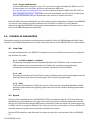
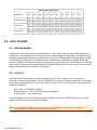
Interface Module User Guide
SIM2000-24
24-Port SDSL Inverse Multiplexer with TC/PAM (G.SHDSL), 2B1Q and CAP Line Encoding
CAUTION Net to Net Technologies strongly recommends the use of proper electrostatic discharge (ESD) precautions when
handling this equipment.
1.0
INSTALLATION
1.1
Unpack and inspect the SIM2000-24
If there is visible damage, do not attempt to connect the device; contact Customer Support at 1-877638-2638 (001-603-427-0600 for international customers) or [email protected].
1.2
Install the SIM2000-24 in an IP DSLAM chassis
NOTE There must be a Multiplexer Uplink Module (MUM) installed in the IP DSLAM chassis in order for interface modules
to operate.
Net to Net Technologies' IP DSLAM interface modules are hot swappable; installing or removing an
interface module while the chassis is powered up does not affect the operational status of other
interface modules within the chassis. The IPD12000 is a fourteen slot chassis; slots 1-12 are reserved
for interface modules (such as the SIM2000-24) and slots 13-14 are reserved for MUMs. Interface
modules may be placed in any order in slots 1-12. The IPD4000 is a five slot chassis; slots 1-4 are
reserved for interface modules and slot 5 is reserved for a MUM.
z
1.3
Align the SIM2000-24 with the slot module guides of the chosen slot for installation
(slot 1-12 on the IPD12000 or slot 1-4 on the IPD4000)
z
Slide the SIM2000-24 firmly into the chassis: DO NOT USE EXCESS FORCE
z
Secure the SIM2000-24 by tightening the fastening screws on the module faceplate
z
Verify that the PWR (Power) LED on the SIM2000-24 faceplate is illuminated
Connect the SDSL Line(s)
Plug the SDSL cable RJ21 connector into the corresponding RJ21 port on the back of the IP DSLAM. For
most applications, a SIM2000-24 SDSL link requires a STRAIGHT-THROUGH DSL CABLE. The SIM200024 can be connected with a remote SDSL subscriber unit via either a single SDSL line or double SDSL
lines (loop bonding). For each port being connected to a remote SDSL subscriber unit, verify that the
210-0000049 rev 05
SDSL link has been established; the SDSL LK LED for that port will pulse green to indicate the
connection has been made. Link up time can vary from one to five minutes depending on the quality,
gauge and distance of the copper cables.
SDSL RJ21 Port Pinout
1
PORT
SDSL
Tip
2
3
4
5
6
7
8
9
10 11 12 13 14 15 16 17 18 19 20 21 22 23 24
26 27 28 29 30 31 32 33 34 35 36 37 38 39 40 41 42 43 44 45 46 47 48 49
Ring 1
2
3
4
5
6
7
8
9
10 11 12 13 14 15 16 17 18 19 20 21 22 23 24
(pins 25 and 50 are not used)
1.3.1
Loop Bonded SDSL Connection
Using two SDSL lines for one network connection (loop bonding) will net twice the speed and data
passing capability as a single-line SDSL connection. A second SDSL line can also be considered a
backup for the first, and vice versa, should either line become disabled. Any two SIM2000-24
ports (consecutive or not) may be connected to an SNE2020-S or SNE2020G-S subscriber unit to
establish a loop bonded connection.
NOTE Net to Net Technologies strongly suggests that any ports on the SIM2000-24 intended for a loop bonded
connection with an SNE2020-S or SNE2020G-S be identically configured prior to connection; bonding ports
with different configurations will likely result in misplaced, misdirected and/or dropped data. See the NMS
Management User Guide and /or the CLI and SNMP Management User Guide for configuration instructions.
If default settings are to be used for both ports, then prior configuration is not necessary and you may
proceed with installation.
1.3.2
Single Line SDSL Connection
A single line connection can be established between a SIM2000-24 and any of Net to Net's SDSL
subscriber units.
1.3.3
Bandwidth and Line Code
There are nine bandwidth options for SIM2000-24 SDSL connections. Distance capabilities vary,
dependent upon the type of line code being utilized. The defaults are TC/PAM line encoding
(G.SHDSL) at 272 kbps. See Section 4.0 SIM2000-24 Parameters for more detailed information
regarding bandwidth and line code.
2.0
DEFAULT SETTINGS
No configuration is necessary for the SIM2000-24 to operate at default settings.
CONFIGURATION
DEFAULT
CONFIGURATION
DEFAULT
Line Code
TC/PAM (G.SHDSL)
Protocol
All
Circ. ID (Circuit Indentification) n/a (no default)
VLAN Ranges (1-10) 0 - 0 (off)
IP Range 1
0.0.0.0 - 255.255.255.255
Backbone-VLAN
0 (off)
IP Range 2
0.0.0.0 - 0.0.0.0
Pri (VLAN Priority)
0 (none)
Speed:
272 kbps
Flood
Upl (Uplink)
210-0000049 rev 05
3.0
SIM2000-24 MANAGEMENT
Once the SIM2000-24 has been installed, line code, bandwidth and all other configurations are software
selectable. Dependent upon the MUM model installed in your DSLAM, the SIM2000-24 can be configured via
Command Line Interface (CLI), Simple Network Management Protocol (SNMP) and/or Net to Net
Technologies' web-based Network Management System (NMS). For further information regarding SIM200024 management and configuration please refer to Net to Net Technologies' NMS Management User Guide
and/or CLI and SNMP Management User Guide.
3.1
Via NMS
Net to Net Technologies' Network Management System (NMS) is an embedded web server that resides
within the firmware of IP DSLAM MUMs (select models only). This web server maintains statistical and
configuration data for the SIM2000-24 and includes a scaled-down version of Simple Network
Management Protocol (SNMP v1.0).
NOTE If your IP DSLAM is newly installed and has not yet been set up for management access, you must configure the IP
Address, Subnet Mask and Gateway (via either NMS or CLI) before you will be able to access data or complete any
other configurations. See the NMS Management User Guide or the CLI and SNMP Management User Guide for initial
configuration instructions.
3.1.1
Establish a Connection with the IP DSLAM MUM
Establish a connection with your IP DSLAM MUM either directly (through the Ethernet RJ45 MGMT
Port on the MUM faceplate) or, if the system has been so configured, from a PC on your local
network. For direct connections, verify that the MGMT LNK LED on the MUM faceplate is
illuminated (indicating the connection has been established).
3.1.2
Launch a Web Browser
Launch a web browser on your PC such as Microsoft Internet Explorer (v4.0 or higher) or
Netscape Navigator (v4.0 or higher).
3.1.3
Enter the IP Address
Enter the DSLAM's IP address* into the address field at the top of your browser window. Press the
Enter key.
3.1.4
Log In
Log in with your assigned username and password.* Please note that General Users have read
only access; for SIM2000-24 configuration you must log in as a Superuser.
*If the IP address, username and/or password are unknown, contact your System Administrator
or Information Technology Manager for assistance.
Once you have logged in as a Superuser, you may make configuration changes to the SIM2000-24, and
any other interface modules installed in the IP DSLAM, as desired. For more detailed information
regarding SIM2000-24 parameters and configuration, refer to Section 4.0 of this manual and/or the
NMS Management User Guide.
210-0000049 rev 05
3.2
Via CLI
Interface modules in an IP DSLAM with a Command Line Interface (CLI) compatible MUM (select
models only) can be managed with a Terminal Emulator program (loaded onto your PC) via a set of
commands and sub-commands/qualifiers.
3.2.1
Establish a Connection with the IP DSLAM MUM
Establish a direct connection with the MUM through the RS232 COM Port on the MUM faceplate.
3.2.2
Launch a Terminal Emulator
Launch a Terminal Emulator program on your PC. Net to Net Technologies copyright information
will appear on your screen followed by a request for username.
3.2.3
Log in
Log in with your assigned username*. Once your username has been entered, a request for
password* will appear. Please note that for SIM2000-24 configuration you must log in as a
Superuser (General Users have read only access).
*If your username and/or password are unknown, contact your System Administrator or
Information Technology Manager for assistance.
Once you have logged in as a Superuser, you may make configuration changes to the SIM2000-24, and
any other interface modules installed in the IP DSLAM, as desired. For more detailed information
regarding SIM2000-24 parameters and configuration, refer to Section 4.0 of this manual and/or the
CLI and SNMP Management User Guide.
3.3
Via SNMP
Simple Network Management Protocol (SNMP) is the standard for management of Transmission
Control Protocol/Internet Protocol (TCP/IP) networks and network devices. Interface modules in an IP
DSLAM with an SNMP compatible MUM can be managed with a MIB Browser program (loaded onto
your PC) via a set of Object Identifiers (OIDs). OIDs are strings of numbers specifying various
configuration commands and requests for data.
NOTE If your IP DSLAM is newly installed and has not yet been set up for management access, you must configure the IP
Address, Subnet Mask and Gateway (via either NMS or CLI) before you will be able to utilize SNMP. See the NMS
Management User Guide or CLI and SNMP Management User Guide for initial configuration instructions.
3.3.1
Establish a Connection with the IP DSLAM MUM
Establish a connection with the MUM either directly (through the Ethernet RJ45 MGMT port on the
MUM faceplate) or, if the system has been so configured, from a PC on your local network. For
direct connections verify that the MGMT LNK LED on the MUM faceplate is illuminated (indicating
the connection has been established).
210-0000049 rev 05
3.3.2
Launch a MIB Browser
Launch a MIB Browser program on your PC. If you have not yet downloaded the MIBs to your PC
or local network, you can obtain the Net to Net enterprise MIBs from
ftp://ftp.nettonet.com/download/mibs and the supported portions of MIB-II from RFC 1213 at
http://www.ietf.org/rfc.html . Once these have been downloaded, you will need to compile them
into your MIB Browser; see your MIB Browser user manual for further instruction.
Once the MIBs have been downloaded, you will be able to make configuration changes to the SIM200024, and any other interface modules installed in the IP DSLAM, as desired. For more detailed
information regarding SIM2000-24 parameters and configuration, refer to Section 4.0 below and /or
the CLI and SNMP Management User Guide.
4.0
SIM2000-24 PARAMETERS
Parameters common to all interface module models are defined in both the NMS Management User Guide
and the CLI and SNMP Management User Guide. Parameters specific to the SIM2000-24 are outlined below.
4.1
Line Code
Line code configuration for the SIM2000-24 applies to all ports; individual ports cannot be configured
with different line codes.
4.1.1
TC/PAM (G.SHDSL) - DEFAULT
Transmission Convergence/Pulse Amplitude Modulation (TC/PAM) line code is a sixteen-level
PAM technique which incorporates advanced Trellis code, precoding, spectral shaping,
equalization circuits and forward error correction. Otherwise known as G.SHDSL.
4.1.2
CAP
Carrierless Amplitude and Phase (CAP) line code modulates transmit and receive signals into two
wide-frequency bands that can pass through a filter without being attenuated.
4.1.3
2B1Q
Two Binary, One Quaternary (2B1Q) line code is a four-level Pulse Amplitude Modulation (PAM)
technique which reduces the signaling rate to half of the bit rate, thereby doubling transmission
efficiency.
4.2
Speed
There are nine bandwidth options for SIM2000-24 SDSL connections; default is 272 kbps. Distance
capabilities vary, dependent upon the type of line code being utilized. Distances listed below assume
the use of 26 American Wire Gauge (AWG) cable; connections made with cable of a greater gauge (e.g.,
24 AWG) will link up at greater distances. The units may not link up if the cable is in poor condition or if
the cable distance is greater than a particular bandwidth will support.
Remote SDSL subscriber units determine line speed through their communication with the SIM200024.
210-0000049 rev 05
SDSL Distance Capabilities
BANDWIDTH
G.SHDSL Distance
CAP Distance
2B1Q Distance
5.0
kbps
2,320
Feet
11,300 12,200 12,800 16,000 16,800 18,400 19,400 20,200 25,400
Meters 3,444
Feet
3,719
1,552
3,901
1,040
4,877
784
5,121
528
5,608
400
5,913
272
6,157
144
7,742
11,000 11,900 12,600 15,500 16,000 17,900 18,900 23,100 24,700
Meters 3,353
Feet
2,064
3,627
3,840
4,724
4,877
5,456
5,761
7,041
7,529
10,400 10,800 13,400 14,800 15,800 17,400 18,200 19,200 23,800
Meters 3,170
3,292
4,084
4,511
4,816
5,304
5,547
5,852
7,254
DATA STORAGE
5.1
RAM and NVRAM
Configuration backup is inherent in the SIM2000-24. Upon initial power up of the IP DSLAM, default
parameters of the SIM2000-24 will remain in place unless changed through NMS, CLI or SNMP. Once
changed, new configurations will automatically be recorded in both the Random Access Memory (RAM)
of the SIM2000-24 and the Non-Volatile Random Access Memory (NVRAM) of the MUM. While data
stored in SIM2000-24 RAM will be erased if the module is removed from the IP DSLAM or the IP DSLAM
loses power, interface module data stored within MUM NVRAM will remain intact (even if the unit loses
power) unless deliberately cleared or reconfigured.
5.2
Local File
Individual port configurations can be saved locally on your PC as a backup, and/or for use as a
template for future configurations. Once the SIM2000-24 has been configured as desired, the settings
can be flash uploaded through a Trivial File Transfer Protocol (TFTP) tool with a GET command and the
following information:
Host name: [IP DSLAM IP Address]
Remote filename: NVR_CFG.bin.[superuser password]
Local filename: [user preference]
Port configuration files can be flash downloaded FROM a local file TO a SIM2000-24 as well; simply
replace the GET command with a SET command.
NOTE Only individual port configurations can be saved to a local file. Chassis configurations are not flash up or
downloadable; they must be manually configured for each unit.
210-0000049 rev 05
6.0
ADDITIONAL INFORMATION
6.1
LED Indications
LED
State
Indication
Additional Information
PWR (Power)
solid green
SIM2000-24 is
operational
If the Power LED is not illuminated, it is unlikely
the SIM2000-24 is receiving power and none of
the LEDs will be illuminated.
SDSL LK (Link)
pulsing
green
SDSL connection is
established and
active
The SDSL link is operational and traffic is flowing.
solid green
problematic SDSL
connection
A connection exists but there is indication of a
problem with the SDSL line.
no
illumination
no SDSL connection
flashing
amber
SDSL activity
The port is receiving either data from the remote
SDSL subscriber unit or statistical packets from
the IP DSLAM management.
solid amber
heavy Rx traffic
The port is receiving large amounts of data from
the remote SDSL subscriber unit.
no
illumination
no activity
A link may exist but the port is not receiving any
data from the remote SDSL subscriber unit.
flashing
amber
SDSL activity
The port is transmitting data to the remote SDSL
subscriber unit.
solid amber
heavy Tx traffic
The port is transmitting large amounts of data to
the remote SDSL subscriber unit.
no
illumination
no activity
A link may exist but the port is not transmitting
any data to the remote SDSL subscriber unit.
SDSL RX
(Receiving)
SDSL TX
(Transmitting)
(A pulsing LED blinks steadily at a rate of once per second. A flashing LED blinks at a more
rapid, less constant rate.)
6.2
Regulatory Compliance for Class A Equipment
6.2.1
US Federal Communications Commission (FCC)
Note: This equipment has been tested and found to comply with the limits for a Class A digital
device, pursuant to part 15 of the FCC Rules. These limits are designed to provide reasonable
protection against harmful interference when the equipment is operated in a commercial
environment. This equipment generates, uses and can radiate radio frequency energy and, if not
installed and used in accordance with the instruction manual, may cause harmful interference to
radio communications. Operation of this equipment in a residential area is likely to cause harmful
interference in which case the user will be required to correct the interference at his own
expense.
Caution: Changes or modifications not expressly approved by the manufacturer could void the
user’s authority to operate the equipment.
210-0000049 rev 05
6.2.2
Industry Canada
This Class A digital apparatus complies with Canadian ICES-003.
Cet appareil numérique de la Classe A est conforme à la norme NMB-003 du Canada.
6.2.3
Europe
This Class A product complies with European Norm EN55022.
Warning: In a domestic environment this product may cause radio interference in which case the
user may be required to take adequate measures to correct the situation.
210-0000049 rev05
© Copyright 2002 Net to Net Technologies, Inc.
™ The Net to Net Logo is a trademark of Net to Net Technologies, Inc.
Worldwide Headquarters
Net to Net Technologies
112 Corporate Drive
Portsmouth, NH 03801
USA
+1 877-638-2638
210-0000049 rev 05
http://www.NetToNet.com/
[email protected]
EMEA Headquarters
Net to Net Technologies
Victoria House 19 Park Way
Newbury Berkshire RG14 1EE
UK
+44 (0) 1635 570950