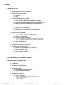
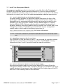
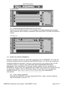
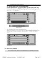
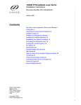
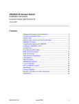
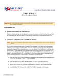
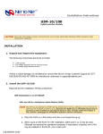
1
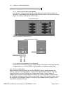
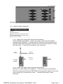
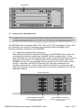
Installation Instructions
IPD4000E
4-Module IP DSLAM: Internet Protocol Digital Subscriber Line Access Multiplexer
© Copyright 2004 Net to Net Technologies, Inc.
™ The Net to Net Logo is a trademark of Net to Net Technologies, Inc.
Worldwide Headquarters
Net to Net Technologies
112 Corporate Drive
Portsmouth, NH 03801 USA
1 (877) 638-2638
[email protected]
http://www.NetToNet.com
IPD4000E Installation Instructions 220-0000097 rev01
EMEA Headquarters
Net to Net Technologies
Victoria House, 19 Park Way
Newbury Berkshire RG14 1EE UK
44 (0) 1635-570950
[email protected]
Page 1 of 17
Contents
1.0 INSTALLATION
1.1 Unpack and Inspect the Equipment
1.2 Select a Site for Installation
1.2.1 Tabletop
1.2.2 Rack
1.3 Install Your Management Module
1.3.1
1.3.2
1.3.3
1.3.4
Install an Uplink Module on the Management Module
Identify the Appropriate Slot for Installation
Align the Management Module with the Slot Module Guides
Slide the Management Module Firmly into the Chassis
1.4 Install Your Interface Module(s)
1.4.1 Select a Slot for Installation
1.4.2 Align the Interface Module with the Slot Module Guides
1.4.3 Slide the Interface Module Firmly into the Chassis
1.5 Power Up Your IPD4000E
1.5.1 Establish a Ground Connection
1.5.1.1 Connect a Ground Wire to the IPD4000E
1.5.1.2 Connect the Ground Wire to a Frame Ground
1.5.2 Select a Terminal Block
1.5.3 Establish a Power Connection
1.5.3.1 Connect Your Positive Power Lead to the Terminal Block
1.5.3.2 Connect Your Negative Power Lead to the Terminal Block
1.5.3.3 Connect Both Power Leads to a Fuse Panel
1.5.4 Verify the Connection
1.6 Establish Your Uplink Connections
1.7 Connect Your Subscriber Lines
1.7.1
1.7.2
1.7.3
1.7.4
1.7.5
Identify the Appropriate RJ21 Connector(s)
Detach the Velcro Strap
Position the RJ21 Connector
Secure the RJ21 Connector
Verify The Connection(s)
1.8 Secure the Connecting Cables
2.0 CONFIGURATION AND MANAGEMENT
3.0 ADDITIONAL INFORMATION
3.1 Fan Module
3.2 IPD4000E Interface Capacity
3.3 Technical Support
3.3.1 Net to Net Technologies' Web Site
3.3.2 Technical Support Engineers
3.4 Regulatory Compliance
3.4.1 Site Selection Criteria
3.4.2 Class A Equipment
3.4.2.1 US Federal Communications Commission (FCC)
3.4.2.2 Industry Canada
3.4.2.3 Europe
IPD4000E Installation Instructions 220-0000097 rev01
Page 2 of 17
1.0 INSTALLATION
CAUTION Net to Net Technologies strongly recommends the use of proper electrostatic discharge (ESD) precautions when
handling this equipment.
1.1 Unpack and Inspect the Equipment
The following components should be included:
1 IPD4000E with 1 fan module and 12 blank plates
CHASSIS SPECIFICATIONS
4 Rubber Bumper Screws
2 Rack Mount Brackets (either 19" or 23", as ordered)
7" High x 17" Wide x 18" Deep
10 #6 Phillips Bracket Screws
(17.8 cm x 43.2 cm x 46 cm)
8 #10 Phillips Rack Screws
28 lbs (12.73 kg)
8 #12 Phillips Rack Screws
If there is visible damage, do not attempt to connect the device. Contact Customer
Support: customers in Europe, the Middle East and Africa please call 44-0-1635570953 or email [email protected]; customers in the United States please
call 1-877-638-2638 or email [email protected]. All other customers please call 1603-427-0600 or email [email protected].
1.2 Select a Site for Installation
NOTE The IPD4000E is designed for installation in a Restricted Access area where admittance is limited to trained and
authorized service personel.
OPERATING REQUIREMENTS
Operating Temperature: -40°F to 149°F (-40°C to 65°C)
Non-Operating Temperature: -40°F to 158°F (-40°C to 70°C)
Humidity: 5% to 95%, non-condensing
Altitude: -200ft to 16,500ft (-60m to 5,000m)
1.2.1 Tabletop
Insert the four [4] provided rubber bumper screws into the mounting holes at the
bottom four corners of the IPD4000E chassis for surface grip. Position and secure
all connecting cables such that they will not become a tripping hazard or pull
loose from the chassis. Ensure that the air supply vents around the top and
bottom edges of the chassis are not blocked.
IPD4000E BOTTOM VIEW
RUBBER BUMPER
SCREW
Top
Side
Front
Rear
IPD4000E Installation Instructions 220-0000097 rev01
Page 3 of 17
1.2.2 Rack
Using a Phillips Screwdriver, attach the two [2] provided rack mount brackets to
the sides of the IPD4000E with eight [8] of the ten [10] provided bracket screws.
There are seven position options for the rack brackets; position them as best
suited to the space available for your chassis on the rack being utilized.
RACK MOUNT
BRACKET
IPD4000E SIDE VIEW
Front
Mount the chassis onto the rack and secure the rack mount brackets to the sides
of the rack using one of the two provided sets of eight [8] rack screws (whichever
size fits the rack being utilized).
IPD4000E FRONT VIEW
Check the rack for stability, ensuring that installation of the IPD4000E has not
caused the rack to become top-heavy.
IPD4000E Installation Instructions 220-0000097 rev01
Page 4 of 17
1.3 Install Your Management Module
A management module provides the functional control for Net to Net Technologies'
IPD4000E; the IPD4000E cannot function without one. There are several different
models available for purchase: refer to http://www.nettonet.com/products for further
information or contact your Net to Net sales representative to discuss your options.
1.3.1 Install an Uplink Module on the Management Module
An uplink module provides the upstream network connection for Net to Net
Technologies' IPD4000E; a management module cannot function without one.
Depending on the management module model that you plan to install in your
IPD4000E, you will need either a Media Interface Module (MIM) or an Uplink
Interface Module (UIM). Only one uplink module is required for operational
purposes, however two uplink modules may be installed, one in each port of the
management module, if redundancy is desired. Refer to your management
module and/or uplink module installation instructions at
http://www.nettonet.com/support/docs for further information.
CAUTION If a blank plate is removed from a management module uplink port, it must be replaced with an uplink
module. DO NOT OPERATE AN IPD4000E WITH A MANAGEMENT MODULE THAT HAS AN OPEN UPLINK
PORT.
1.3.2 Identify the Appropriate Slot for Installation
The IPD4000E is a five slot chassis: slots 1-4 are reserved for interface modules
and Slot U1 is reserved for a management module. The IPD4000E is factory
shipped with slots 1 and U1 open and ready for module installation.
Management Module Slot
1.3.3 Align the Management Module with the Slot Module Guides
With the management module printed circuit board (PCB) facing UP and the
management module model name, and Net to Net logo, on the RIGHT side of the
module faceplate (facing towards you), align the left and right edges of the PCB
with the U1 slot module guides on the IPD4000E.
IPD4000E Installation Instructions 220-0000097 rev01
Page 5 of 17
MANAGEMENT MODULE
Slot Module Guides
1.3.4 Slide the Management Module Firmly into the Chassis
Tighten the fastening screws on the management module faceplate by turning
them clockwise with a Phillips screwdriver. Be careful NOT TO OVER-TIGHTEN the
screws.
Fastening Screws
1.4 Install Your Interface Module(s)
Interface modules provide the subscriber connections for an IPD4000E; up to four [4]
interface modules may be installed in the IPD4000E (slots 1-4). There are a variety of
models available for purchase; visit http://www.nettonet.com/products for a list of
available products or contact your Net to Net sales representative for further
information. Any combination of interface module models may be installed in an
IPD4000E as long as they are supported by the model type and version number of your
management module; refer to the Release Notes for your particular management
module model at http://www.nettonet.com/support/docs for compatibility
information.
1.4.1 Select a Slot for Installation
Although the IPD4000E is factory shipped with Slot 1 open, interface modules
may be installed in any slot, 1-4.
IPD4000E Installation Instructions 220-0000097 rev01
Page 6 of 17
CAUTION If a blank plate is removed from slot 2-4, it must be replaced with an interface module. DO NOT OPERATE
YOUR IPD4000E WITH AN EMPTY MODULE SLOT.
1.4.2 Align the Interface Module with the Slot Module Guides
With the interface module PCB facing UP and the interface module model name,
and Net to Net logo, on the RIGHT side of the module faceplate (facing towards
you), align the left and right edges of the PCB with the slot module guides of the
chosen slot on the IPD4000E.
Slot Module Guides
INTERFACE MODULE
1.4.3 Slide the Interface Module Firmly into the Chassis
Tighten the fastening screws on the interface module faceplate by turning them
clockwise with a Phillips screwdriver. Be careful NOT TO OVER-TIGHTEN the
screws.
Fastening Screws
1.5 Power Up Your IPD4000E
CAUTION Turn your DC power source(s) OFF until you have completed connection of the IPD4000E as outlined below.
IPD4000E Installation Instructions 220-0000097 rev01
Page 7 of 17
1.5.1 Establish a Ground Connection
CAUTION DO NOT operate your IPD40000E without a ground connection.
1.5.1.1 Connect a Ground Wire to the IPD4000E
Line up the 2-hole terminal lug of your ground wire with the two holes on
the small, unpainted section on the back of your chassis. Secure the terminal
lug to the chassis with two #10-32 screws.
IPD4000E REAR VIEW
Ground Connection for 2-Hole Terminal Lug
GROUND CONNECTION CLOSE-UP
1.5.1.2 Connect the Ground Wire to a Frame Ground
Ground wire connection can vary from location to location, although typically
all equipment in a Central Office is grounded to a common copper bus.
1.5.2 Select a Terminal Block
Either terminal block on the back of the IPD4000E may be used to power the
chassis; only one terminal block is required for operational purposes. The two
terminal blocks on the IPD4000E are independent feeds. Chassis power is
supplied by only one terminal block at a time; the second supply is merely backup. Likewise, the two terminal blocks do not load-share. Each terminal block must
be supplied with adequate Amps to run the chassis independently; power is not
cumulative between the two.
IPD4000E Installation Instructions 220-0000097 rev01
Page 8 of 17
DC Terminal Blocks
1.5.3 Establish a Power Connection
DC POWER SPECIFICATIONS
-48V DC
10 Amps maximum
Although actual power draw depends upon
chassis configuration, a fully loaded chassis
averages around 6 Amps.
1.5.3.1 Connect Your Positive Power Lead to the Terminal Block
Using a Phillips Screwdriver, remove the upper screw from the chosen
terminal block (labeled "+" on the chassis). Slide the ring terminal of your
positive power lead around the shaft of the screw and re-insert the screw
into the same "+" terminal from which it was removed.
Ring
Terminal
POSITIVE
POWER LEAD
Positive (+)
Terminal
DC POWER
TERMINAL
1.5.3.2 Connect Your Negative Power Lead to the Terminal Block
Remove the right-hand screw (labeled "-") from the same terminal block.
Slide the ring terminal of your NEGATIVE lead around the shaft of the screw
and re-insert the screw into the same "-" terminal from which it was
removed.
IPD4000E Installation Instructions 220-0000097 rev01
Page 9 of 17
Negative (-)
Terminal
DC POWER
TERMINAL
NEGATIVE
POWER LEAD
Ring
Terminal
CAUTION Be sure to attach THE POSITIVE LEAD TO THE POSITIVE TERMINAL and the NEGATIVE LEAD TO THE
NEGATIVE TERMINAL as indicated on your IPD4000E terminal block labels.
1.5.3.3 Connect Both Power Leads to a Fuse Panel
The negative (-) lead connects to a "Batt" (Battery) terminal and the positive
(+) lead connects to a "Return" terminal on your DC power supply.
CAUTION The power source(s) connected to the IPD4000E must be equipped with a disconnect device such
as an On/Off switch. Otherwise, an appropriately rated circuit breaker must be installed on each
power circuit to be used. In the case of an emergency, hazardous voltages will not be removed
from the IPD4000E until all power sources have been either turned off or disconnected from the
chassis.
1.5.4 Verify the Connection
Turn your power source(s) on. The PWR (power) LED on both the interface module
and management module faceplates will illuminate solid green to indicate the
modules are receiving power.
MANAGEMENT
MODULE
Power LED
INTERFACE
MODULE
Power LED
1.6 Establish Your Uplink Connections
NOTE No configuration is necessary for Uplink Interface Modules (UIMs) or Media Interface Modules (MIMs), as installed on
the management module(s) in your IPD4000E, to operate at default settings. However, if you wish to run your uplink
connections at settings other than the UIM or MIM defaults, Net to Net recommends configuring the UIM or MIM
prior to connection.
For further connection and configuration information, refer to the installation
instructions of your particular UIM or MIM model at
http://www.nettonet.com/support/docs .
IPD4000E Installation Instructions 220-0000097 rev01
Page 10 of 17
Uplink Module
1.7 Connect Your Subscriber Lines
NOTE No configuration is necessary for the interface module(s) installed in your IPD4000E to operate at default settings.
However, if you wish to run your subscriber connections at settings other than the factory defaults, Net to Net
recommends configuring the interface module(s) prior to connection. Refer to the installation instructions for your
particular interface module model(s) at http://www.nettonet.com/support/docs for configuration information.
The IPD4000E chassis supports ADSL, IDSL, SDSL and T1/E1 technologies. Ensure that
the subscriber lines you are connecting correspond with the technology of the
interface module(s) installed in your IPD4000E.
1.7.1 Identify the Appropriate RJ21 Connector(s)
Subscriber lines must be connected according to the IPD4000E slot in which the
corresponding interface module was installed. Interface module slots 1-4 run
from bottom to top; the corresponding RJ21 ports are directly behind each slot on
the back of the chassis (1-4, bottom to top). Each interface module slot on the
IPD4000E has two [2] corresponding RJ21 connectors on the back of the chassis:
the RJ21 connectors on the left (A) provide the subscriber connections for
interface module ports 1-24 (on most models) and the RJ21 connectors on the
right (B) provide the subscriber connections for interface module ports 25-48 (on
applicable models).
IPD4000E REAR VIEW
Interface Module B connectors
subscriber connections for ports 25-48 (on applicable models)
IPD4000E Installation Instructions 220-0000097 rev01
Interface Module A Connectors
subscriber connections for ports 1-24 (on most models)
Page 11 of 17
EXCEPTION For the TIM1500-24 and EIM2000-24 interface modules, the A connectors provide the subcriber
connections for ports 1-12 and the B connectors provide the subscriber connections for ports 13-24.
1.7.2 Detach the Velcro Strap
Detach the Velcro Strap from the female RJ21 connector port: lift the Velcro tab
from the bottom and pull the strap upward to open, leaving it looped under the
right side of the connector frame.
FEMALE RJ21 CONNECTOR A
FOR INTERFACE MODULE SLOT 3
1.7.3 Position the RJ21 Connector
Slide the male RJ21 connector of your interface cable underneath the Velcro, from
the left, and press it firmly into the female RJ21 connector port on the chassis.
MALE RJ21 CONNECTOR OF
YOUR INTERFACE CABLE
1.7.4 Secure the RJ21 Connector
Pull the Velcro strap upward, making sure that it is snug against the connector,
then pull the strap back down, such that the Velcro layers stick to one another
across the top of the connector.
IPD4000E Installation Instructions 220-0000097 rev01
Page 12 of 17
Tuck the tab at the end of the strap down between the connector frames so that it
is out of the way of other connections.
Screw the right side of the RJ21 cable connector into the jack screw on the right
side of the RJ21 connector frame on the chassis.
NOTE If you are using a 120 or 180 degree cable, both the right and left sides of the cable connector should be
screwed to the RJ21 connector frame on the chassis.
1.7.5 Verify The Connection(s)
The LK (Link) LED for each port being connected with a remote modem will
illuminate solid or flashing green to indicate a connection has been established.
Link up time between interface modules and remote modems can vary from one
to five minutes depending on the quality, gauge and distance of the copper cable
pair(s) being used. Refer to individual interface module user guides at
IPD4000E Installation Instructions 220-0000097 rev01
Page 13 of 17
http://www.nettonet.com/support/docs for specific information such as
connector pinouts, parameter configurations and distance capabilities.
1.8 Secure the Connecting Cables
Position all connecting cables such that they will not become a tripping hazard or pull
loose from the chassis; secure with cable ties or velcro straps.
2.0 CONFIGURATION AND MANAGEMENT
Although no configuration is necessary to run subscriber lines at Net to Net Technologies'
default settings, all IPD4000E parameter settings are software selectable via Command Line
Interface (CLI), Simple Network Management Protocol (SNMP) and/or Net to Net's Network
Management System (NMS). IPD4000E management capabilities depend upon the
management module model installed in your chassis. Once the management module has
been initialized, the interface modules installed in your IPD4000E may also be configured as
desired.
Refer to the following documentation at http://www.nettonet.com/support/docs for further
information:
DOCUMENT
management module installation instructions
(model-specific)
uplink module installation instructions
(model-specific)
interface module user guides
(model-specific)
CONTENTS
module installation
port pinouts
parameter defaults
parameter configuration options
management system capabilities
module installation
port pinouts
parameter defaults
parameter configuration options
module installation
distance and bandwidth capabilities
port pinouts
parameter defaults
parameter configuration options
CLI Management User Guide
management module initialization instructions
command user guide
command definitions
configuration options common to all management module models
configuration options common to all interface module models
NMS Management User Guide
management module initialization instructions
screen by screen user guide
parameter definitions
configuration options common to all management module models
configuration options common to all interface module models
IPD4000E Installation Instructions 220-0000097 rev01
Page 14 of 17
3.0 ADDITIONAL INFORMATION
3.1 Fan Module
The IPD4000E fan module is installed vertically to the right of the interface module
slots. It comes pre-installed and should not be removed unless it is being replaced. Fan
functionality is indicated by a FAN LED on your management module (all models): NO
illumination or solid GREEN illumination indicates all fans are currently functioning,
solid AMBER illumination indicates one or more of the four fans are no longer
functioning.
IPD4000E FRONT VIEW
Fan Module MANAGEMENT MODULE
Fan LED
CAUTION Do not operate the IPD4000E without a fan module or with a fan module that is not functioning properly.
3.2 IPD4000E Interface Capacity
4 interface module slots
1 management module slot
8 RJ21 50-pin female Telco connectors
3.3 Technical Support
3.3.1 Net to Net Technologies' Web Site
The following information can be found at http://www.nettonet.com/support :
DSL Distance and Bandwidth Quick Reference Chart
Firmware Downloads (for applicable modules)
IPD4000E Installation Instructions 220-0000097 rev01
Page 15 of 17
Frequently Asked Questions
Net to Net Enterprise MIBs
Product Discontinuation Notices
Product Documentation
Visio Network Diagram Stencils
3.3.2 Technical Support Engineers
If you are unable to locate the answers to your questions online, please contact
Net to Net Technologies' Technical Support Department directly:
CUSTOMER LOCATION
TECH SUPPORT EMAIL
TECH SUPPORT PHONE
Europe, Middle East and Africa
[email protected]
44-0-1635-570953
United States
[email protected]
1-877-638-2638
all other locations
[email protected]
1-603-427-0600
3.4 Regulatory Compliance
NEBS: GR-63-CORE; GR-1089-CORE
EMC: FCC Part 15; CSA/C108.8; EN55022; EN55024
SAFETY: UL 60950-1 1st Edition, UL Marking; CSA 22.2 No. 60950-1-03; EN60950-1:2001; CE
Marking
TELECOM: ACTA968 (Part 68); ICCS-03; TBR12; TBR13
3.4.1 Site Selection Criteria
In choosing a location for the installation of this product:
z
z
z
z
z
z
z
z
Select a RESTRICTED ACCESS area where admittance is limited to trained and
authorized service personnel.
Ensure that the internal temperature of a rack containing this equipment will
not exceed the maximum recommended ambient temperature of 149°F (65°
C).
Place the chassis such that connecting cables will not become a tripping
hazard or pull loose from the chassis.
Do not block power supply vents or otherwise restrict airflow when installing
this equipment.
Ensure that installation of this equipment in a rack will not cause the rack to
become top-heavy or unstable.
Do not overload the electrical branch circuit of the power source for this
equipment.
For tabletop use, attach the enclosed rubber feet to the bottom of the
chassis.
For rack installation, attach the enclosed rack mount brackets to the sides of
the chassis with the screws provided.
3.4.2 Class A Equipment
3.4.2.1 US Federal Communications Commission (FCC)
Note: This equipment has been tested and found to comply with the limits
for a Class A digital device, pursuant to part 15 of the FCC Rules. These
IPD4000E Installation Instructions 220-0000097 rev01
Page 16 of 17
limits are designed to provide reasonable protection against harmful
interference when the equipment is operated in a commercial environment.
This equipment generates, uses and can radiate radio frequency energy and,
if not installed and used in accordance with the instruction manual, may
cause harmful interference to radio communications. Operation of this
equipment in a residential area is likely to cause harmful interference in
which case the user will be required to correct the interference at his own
expense.
Caution: Changes or modifications not expressly approved by the
manufacturer could void the user’s authority to operate the equipment.
3.4.2.2 Industry Canada
This Class A digital apparatus complies with Canadian ICES-003.
Cet appareil numérique de la Classe A est conforme à la norme NMB-003 du
Canada.
3.4.2.3 Europe
This Class A product complies with European Norm EN55022.
Warning: In a domestic environment this product may cause radio
interference in which case the user may be required to take adequate
measures to correct the situation.
© Copyright 2004 Net to Net Technologies, Inc.
™ The Net to Net Logo is a trademark of Net to Net Technologies, Inc.
Worldwide Headquarters
Net to Net Technologies
112 Corporate Drive
Portsmouth, NH 03801
USA
+1 877-638-2638
[email protected]
http://www.NetToNet.com/
EMEA Headquarters
Net to Net Technologies
Victoria House 19 Park Way
Newbury Berkshire RG14 1EE
UK
+44 (0) 1635 570950
[email protected]
IPD4000E Installation Instructions 220-0000097 rev01
Page 17 of 17