1
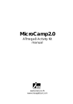
POP-BOT : The Arduino Compatible Mobile Robot kit l 1
Activity manual
version 1.0 Standard
(c) Innovative Experiment Co. ,Ltd.
www.inexglobal.com
2 l POP-BOT : The Arduino Compatible Mobile Robot kit
Cerdits
POP-168 Module, RBX-168 Robot controller board are trademarks of Innovative Experiment
Co., Ltd.
POP-BOT, POP-BOT logo , INEX, and INEX logo are trademarks of Innovative Experiment Co.,
Ltd.
AVR, Atmel, Atmel logo, AVR Studio are registered trademarks of Atmel Corporation.
WinAVR is trademark of SourceForge, Inc.
AVR-GCC is copyright of Free Software Foundation, Inc.
Arduino is an open source project supported by many. The Team is composed of Massimo
Banzi, David Cuartielles, Tom Igoe, Gianluca Martino, and David Mellis. Nicholas Zambetti
has contributed since the beginning. Yaniv Steiner and Giorgio Olivero have been
supporting the project and are working at using it with the Instant Soup platform. The
Arduino platform used to include the avr-gcc tool chain, uisp, and the Procyon AVR-LIB by
Pascal Stang. The Arduino language syntax is based on Wiring by Hernando Barragan.
The Arduino environment is based on Processing by Ben Fry and Casey Reas. Thanks to all
the people who are supporting arduino.
FTDI is a trademark of Future Technology Devices Intl Ltd.
I2C is a registered trademark of Philips Semiconductors.
Microsoft, Windows are registered trademarks of the Microsoft Corporation.
Windows 2K, Windows XP, and Windows Vista are registered trademarks of the Microsoft
Corporation.
All product and service names mentioned herein are the trademarks of their respective
owners.
POP-BOT : The Arduino Compatible Mobile Robot kit l 3
Contents
1 : POP-BOT part list.......................................................................................................................5
2 : Building POP-BOT mobile robot..............................................................................................19
3 : Introduction to Arduino IDE........................................................................................................25
4 : POP-BOT program development by Arduino.......................................................................31
5 : POP-BOT movement activity .................................................................................................41
6 : POP-BOT with Serial LCD........................................................................................................53
7 : POP-BOT line tracking.............................................................................................................63
8 : POP-BOT edge detection........................................................................................................93
9 : POP-BOT touchless object avoiding............................................................................................99
10 : POP-BOT with Servo motor activity....................................................................................109
11 : POP-BOT object seeking ability........................................................................................119
POP-BOT : The Arduino Compatible Mobile Robot kit l 5
1 : POP-BOT part list
1.1 Part list of POP-BOT mobile robot kit
1. POP-168 The Arduino-mini compatible microcontroller module
2. RBX-168 Robot controller board with 4-AA battery holder
3. Switch module with JST cable (2 sets)
4. Infrared Reflector board with JST cable (2 sets)
5. GP2D120 Infrared distance sensor with JST cable
6. Serial LCD 16 characters by 2 lines module with LED backlight and cable
7. 48:1 ratio 4.5V DC motor gearbox with IDC cable (2 sets)
8. Standard servo motor (Operating voltage is 4.8 to 7.2Vdc)
9. Circle wheel and Threaded rubber wheel set with 2mm. tapped-screw. (2 sets)
10. 80x60 cm. and 80x80 cm. Plastic Grid plate set (2 sets)
11. Circle base with idle ball wheels
12. Plastic joiner and Strip joiner set (60 pieces of 3-type mix colored plastic joiner, 4
pieces of each 3/5/12 holes of Strip joiner)
13. Right-angled metal shaft set (4 pieces of each 1x2, 2x2, 2x5 Right-angled metal
shaft)
14. Nuts and Screws set
15. Line tracking demo paper sheet
16. UCON-4 USB to serial converter cable for downloading and communication
17. CD-ROM contains software tools, source code and documentation
6 l POP-BOT : The Arduino Compatible Mobile Robot kit
1.2 Microcontroller components information
1.2.1 POP-168 microcontroller module
The Arduino POP-168 is a flexible board with no hidden components which allows
full development of its features with AVR Standard tools like the like IAR C/C++ ,
MikroElektronika Mikro BASIC/ MikroPascal for AVR, and also the open-source tool WINAVR:
AVRGCC for Windows ... etc.
Arduino POP-168 use the ATmega168 of AVR microcontroller from Atmel
(www.atmel.com). Arduino POP-168ís oin assignment is similar BASIC Stamp module
(www.parallax.com). It includes RS-232 serial port communication circuit for downloading
and data communication with computer. Arduino POP-168 moduleís hardware is
compatibled with Arduino-mini in Arduino project (www.arduino.cc/en)
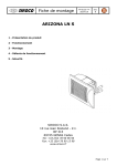
The complete schematic diagram of Arduino POP-168 module is shown in figure 1-1.
The summarize features of POP-168 module is as follows :
l ATmega168 on board with 10-bit ADC converter, 16KB flash program
memory, 512-byte EEPROM, 1KB RAM, 16MHz clock
l Built-in RS-232 interface for Communication
l Immediate code upload with the built-in Bootloader
l Reset Button for reset capability
l Small Form Factor for compact size development
l ISP port for programming with the PX-400/PX-4000 device
l SMD Leds for indications
l Fully compatible with the Ardruino Project
l 16 I/O pin assignement compatible i-Stamp/i-Stamp2P24 module
l Supply voltage range +3.3 to +5V 50mA
1.2.2 RBX-168 Robot controller board for Arduino POP-168
The RBX-168Robot controller board is a complete, low-cost development platform
designed for those interested in learning and using Arduino POP-168 module in robotic
applications. Its compact size, convenient features, and low price make it an ideal tool
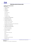
for the student and educator. Figure 1-2 shows the layout of RBX-168 board and complete
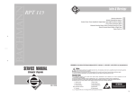
schematic diagram of its is shown in the figure 1-3. The summarized technical feature of
the RBX-168 board is as follows :
POP-BOT : The Arduino Compatible Mobile Robot kit l 7
R1
4k7
R2 R3
10k 4k7
PD2
PD3
PIN13
PIN24
R5
+5V
R6
CR1
16MHz
GND
PB2
MOSI
PD5
PD7
PD6
AN6
AREF
VCC
GND
AGND
AN7
C1
0.1PF
PB1
PB0
PB7
PB6
IC1
ATMega168-20AU
(TQFP32)
AN0
AN1
+5V
2
C6
0.1PF
C3
0.1PF
VCC
GND
4
5
16
IC2
R9
68
R10
150
1
MAX3232
3
C5
0.1PF
7
10
9
PD4
PD3
AN2
C2
0.1PF
C4
0.1PF
+5V
PD2
RST
PB5
AVCC
PD0
PD1
GND
R8
+5V
AN5
RST
SCK
PB3
PB2
GND
R5-R8
150 x4
AN3
AN4
MISO
PB4
R7
GND
Vcc
PD4
PD5
PD6
PD7
PB0
PB1
R4
4k7
K1
AVR
In-System
Programming
Connector
+5V
RST
LED2
Green
+5V +5V LED1
Blue
+5V
+5V
GND
+5V
8
15
6 C7
0.1PF
SW1
BL
Bootloader
Mode switch
AN7
AN6
AN5
AN4
AN3
AN2
AN1
AN0
GND
RX
PIN12
TX
PIN1
+5Vdc
RESET
Program mode : Turn-on
Run mode : Indicates the Di 13 port logic status
ISP connector
pin assignment
GND
GND
GND
GND
+VDD
Di 12 (PB4:MISO)
Di 13 (PB5:SCK) Blue LED
RESET
Di 10 (PB2:SS) PWM
Di 11 (PB3:MOSI) PWM
ATMEGA168
DB-9 female connector
connect to computer's
serial or COM port
2
12
TxD
RxD
NC
GND
An0 (PC0)
An 1 (PC1)
An2 (PC2)
An 3 (PC3)
An4/SDA (PC4)
An5/SCL (PC5)
An 6 (AN6)
An 7 (AN7)
1
BL switch for programming mode selection
Green LED
(power)
13
POP-168
Blue LED operation indicator
NC
GND
RESET
VDD (+5Vdc)
Di 9/PWM (PB1)
Di 8 (PB0)
Di 7 (PD7)
Di 6/PWM (PD6)
Di 5/PWM (PD5)
Di 4 (PD4)
Di 3/PWM (PD3)
Di 2 (PD2)
GND
3
5
Figure 1-1 Schematic diagram, Pin assignment and simple connection of POP168 microcontroller module
8 l POP-BOT : The Arduino Compatible Mobile Robot kit
l Screw terminal block for battery connections. It supports +4.8 to +12Vdc
and has an on-board power switch.
l +5Vdc switching regulator power supply circuit. Its regulates the supply
voltage for POP-168 module and all sensor ports.
l 2-push button switch are connected with the digital port 2 (Di2) and 4
(Di4). Also connnedt with LED for indicator the operation.
l 5-Universal port support Analog input function and Digital input/output
function; An1 (Di15) to An5 (Di19)
l 2-Analog input port ; An6 and An7. Both port pin are analog input only.
l I2C bus port; An4 (SDA) and An5 (SCL)
l RS-232 serial port interfacing.
l 2-ch. DC motor driver with indicators. Support motor voltage 2.5 to 13.5Vdc.
l 2-Servo motor output; connect with the digital port 7 (Di7) and 8 (Di8).
l Piezo speaker connections (do not show in the figure 1-2; it is fixed at bottom
circuit board of RBX-1689 board. It is connected with POP-168 An0/Di14 pin.
RS-232 port
(support the USB to serial converter cable)
Motor indicator
1
RESET
ATMEGA168
16/A2
Port function
A
B
Di2
Number : Digital
Ax : Analog pin x
POP-168
-
+Vm
8
-
Di4
RESET switch
Analog input
Arduino POP-168 module
Figure 1-2 The layout of RBX-168 controller board
Program mode button
(on the Arduino POP168 module)
Servo motor output
+Vm
7
13
A7
12
A6
DC motor output
BAT
15/A1
Arduino POP-168
univeral port
14/A0 18/SDA/A4 19/SCL/A5
Low battery
indicator
POWER
MOTOR
SERVO PORT
POWER indicator
+ON
14: Speaker
3 : MotorA1
5 : MotorA2
9 : MotorB1
6 : MotorB2
POWER switch
ON
4-12Vdc
RS-232
Supply voltage terminal
LED and Button
for demonstration
I/O interfacing
+5V
+5V
+5V
K6
19/A5/SCL
K5
18/A4/SDA
K4
17/A3
K2
15/A1
S2
Di4
LED4
P4
+5V
+5V
R7
510
S1
Di2
R5
510
LED3
P2
+5V
+5V
+5V
K7
An6
K3
16/A2
+5V
3
4
2
1
K8
An7
RxD
TxD
DTR
GND
J1
DOWNLOAD
RJ-11 6P4C
R8
220
R6
220
21
Di2
An1
An2
An3
An4
An5
An6
Di3/PWM
An0/Di14
RESET
Di8
Di7
Di6/PWM
Di9/PWM
Di5/PWM
An7
SK1
POP-168
socket
TxD
RxD
15 Di4
13
6
7
8
9
10
11
12
2
1
+5V
19
18
K10
SERVO2
K9
SERVO1
Di7-SERVO1
+Vm
GND
Di8-SERVO2
+Vm
GND
S
S
S
G
D
D
D
D
FDS6680
15
4
23
16 BIN2
17
3
24
GND
CE OUT NC
EXT
C2
100PF
10V
L1
10uH
AO1
8
7
12
11
+-O
KIA
7031
BO2
BO2
BO1
BO1
AO2 5
6
AO2
2
1
Q1
FDS6680A
AO1
9 10 18
NCP1450
4
PWMB
17 BIN1
PWMA
AIN2
AIN1
20
23
12
14
+Vm
IC4
TB6612FNG
13
19 STBY
20
Vcc
+5V
IC2
KIA78R05
G O I
R2
47k
LED1
LOW-BAT
3
16
+Vm
SP1
PIEZO
GND
2
RESET
1
+V
R1
1k
21
C5
10PF
16V
SW2
RESET
IC1
KIA7031
C1
100PF
16V
D1
1N5819
14
5
22
R4
4.7k
+5V
K1
BATT.
4.8-12V
SW1
ON
+Vm
C6
0.1/63V
OUT
C7
0.1/63V
R10
1k
LED5
MOTOR A-DIR.
R9
1k
GND
CE
LED6
MOTOR B-DIR.
4
5
IC3
NCP1450-5.0
D2
MBR340
K12
MOTOR-B
K11
MOTOR-A
C4
0.01PF
50V
C3
1000PF
6.3V
LED2
ON
R3
1k
+5V
POP-BOT : The Arduino Compatible Mobile Robot kit l 9
Figure 1-3 The completely schematic diagram of RBX-168 controller board
10 l POP-BOT : The Arduino Compatible Mobile Robot kit
1.3 Output device features
1.3.1 DC motor gearbox
This robot kit provides 48:1 ratio DC motor gearbox; model BO-2 with IDC connector
cable. This is features :
l Operating voltage is +3 to +9Vdc
l Current consumption 130mA @ +6Vdc and no load)
l Average speed 170 to 250 round per minute (RPM) @ +6V and no load
l Weight is 30 grams
l Minimum torque is 0.5 kg.cm.
l Attached with the plastic mounting with 5 of insert nuts
l 42 x 45 x 22.7 mm. (WxLxH) dimension
1.3.2 Standard RC servo motor
The standard servo is ideal for robotics and basic movement projects. These servos
will allow a movement range of 0 to 180 degrees. The servo output gear shaft is a standard
Futaba configuration. Technical Specifications are :
l Operating voltage is 6Vdc max.
l Speed 0 deg to 180 deg in 1.5 seconds on average.
l Weight 45.0 grams/1.59oz
l Torque 3.40 kg-cm/47oz-in
l Size mm (L x W x H) 40.5x20.0x38.0
POP-BOT : The Arduino Compatible Mobile Robot kit l 11
1.3.3 SLCD16x2 : 16 characters 2 lines Serial LCD module
The 16x2 Serial LCD module provides a simple way to display data from microcontroller. The module requires only one I/O pin, +5 V and ground to function. Simple
serial data out commands can be used in the Arduino POP-168 module to communicate
with the module at 2400 and 9600 baud.
Features of the 16x2 Serial LCD Module:
l Serial Input with Invert/Non-invert TTL logic level.
l 1/8 or 1/16 Duty can be selected by jumper.
l Scott Edwardsís LCD Serial BackpackTM command compatible addition
with Extended Command that make LCD control easier.
l Operation with +5 Vdc supply
l SLCD16x2 provides a brightness adjustment with variable resistor at
BRIGHTNESS position.
l Interfacing connector has 3 pins : +5V Supply voltage (+), Serial data input
(S) and Ground (G).
12 l POP-BOT : The Arduino Compatible Mobile Robot kit
1.4 Sensor module features
1.4.1 Switch module/Touch sensor
LED1
R1
510
Indicator
+V
R2
10k
R3
220
DATA
Signal output
S1
GND
Switch
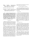
The switch input is used to detect collision at logic ì0î. Two sets along with the
connecting cable are provided.
1.4.2 ZX-03 : Infrared reflector sensor
The heart of this sensor is TCRT5000 reflective object sensor. It is designed for close
proximity infrared (IR) detection. Thereís an infrared diode behind its transparent blue
window and an infrared transistor behind its black window. When the infrared emitted by
the diode reflects off a surface and returns to the black window, it strikes the infrared
transistorís base, causing it to conduct current. The more infrared incident on the transistorís
base, the more current it conducts. When used as an analog sensor, the ZX-03 can detect
shades of gray on paper and distances over a short range if the light in the room remains
constant.
The suitable distance from sensor to line or floor is during 3 to 8 mm. The output
Signal connector
+V
TCRT5000
OUT
GND
10k
510
Infrared Reflector
voltage is during 0.1 to 4.8V and digital value from10-bit A/D converter is 20 to 1,000. Thus,
ZX-03 will suitable to apply to line tracking sensor.
POP-BOT : The Arduino Compatible Mobile Robot kit l 13
1.4.3 GP2D120 Infrared distance sensor
One of the special sensors in robotics is the GP2D120. It is an Infrared Distance
sensor. Some people call it the IR Ranger. With the GP2D120 module, it adds the distance
measuring and Obstacle detection using infrared light feature to your robot. Your
MicroCamp robot can avoid obstacles without having to make any physical contact.
Infrared LED transmitter
Infrared Receiver
/2 , Vout GND
Vcc
Features of the GP2D120 module
l
Uses Infrared light reflection to measure range
l
Can measure a range from 4 to 30 cm.
l
4. 5 to 5 V power supply and 33mA electric current
l
The output voltage range is 0.4 to 2.4V when supplied by +5V
GP2D120 Infrared Ranger module has 3 terminals: Power input (Vcc), Ground (GND)
and Voltage output (Vout). To read the voltage values from the GP2D120, you must wait
till after the acknowledgement period which is around 32 to 52.9 ms.
The output voltage of GP2D120 at a range of 30 cm and +5V power supply is
between 0.25 to 0.55V, with the mean being 0.4V. At the range of 4 cm., the output
voltage will change at 2.25V± 0.3V.
14 l POP-BOT : The Arduino Compatible Mobile Robot kit
1.5 POP-BOT cable information
The POP-BOT mobile robot kit includes some signal cables for the interfacing
between the controller board, sensor module and the computer. They includes the JST3AA8 cables for interconnection to the sensor module, UCON-4 the USB to RS-232 converter
cable for interfacing with the computer.
1.5.1 JST3AA-8 cable
This is an INEX standard cable, 3-wires combined with 2mm. The JST connector is at
each end. 8 inches (20cm.) in length. Used for connecting between microcontroller board
and all the sensor modules in the POP-BOT robot kit. The wire assignment is shown in the
diagram below.
2mm. pitch
GND
S
+5V
GND
2mm. pitch
S/Data
+5V
1.5.2 UCON-4 USB to Serial port converter cable
This is used to connect between the computerís USB port and the RBX-168 controller
board. The cableís end uses a Modular plug RJ-11 6P4C (6-pins form and 4-contacts) Its
Length is 1.5 meters approximation. The cable assignment is shown in the diagram below.
MCU_TxD
GND
MCU_RxD
MCU_DTR
This cable requires +5V from USB port and support USB 1.0/2.0. User can set the
baudrate up to 115,200 bit per second. Requires the driver installation before using.
POP-BOT : The Arduino Compatible Mobile Robot kit l 15
1.6 Mechnical prt features
1.6.1 Circle wheel and Tire set
Includes 2 pairs of the suittable circle wheel for BO-2 DC motor gearbox and tread
rubber tire. Fix the wheel with gearbox shaft by 2mm. self-tapping screws
1.6.2 Plastic grid plate set
Includes each of the universal plastic grid palte 2 sizes; 80x60mm. and 80x80mm.
Each plate provides 3mm. diameter holes with 5mm. pitch.
1.6.3 Circle base
This base is injected from high quality ABS plastic. Diameter is ...........mm. It has 2
free ball wheels at both side. This base has many 3mm. holes for fixing the controller board,
sensors and more mechanical parts.
16 l POP-BOT : The Arduino Compatible Mobile Robot kit
1.6.4 Plastic joiners
60 pieces of varied color joiners made from PVC plastic. They can be connected
together or by using screws and 3 mm nuts in installation. There are 4 types; Right angle,
Obtuse, Straight joiner and Hole straight joiner.
1.6.5 Strip joiners
They are made from plastic. Each joiner has 3mm. hole 5mm. pitch. Each joiner
can connect for lenght expansion. They are 4 pieces of 3 sizes; 3, 5 and 12 holes type.
Total 12 pieces.
1.6.6 Box holder
It is injected plastic box for supporting the RBX-168 controller board. It has some of
3mm. hole for fixing with any platform.
POP-BOT : The Arduino Compatible Mobile Robot kit l 17
1.6.7 Right-angle metal shaft
It is 7.5mm. width right-angle metal shaft. Each shaft has 3mm. hole for inserting the
screw to fix with another structures. The set includes 4 pieces of 1x2, 2x2 and 2x5 holes
metal shaft.
1.6.8 Screw and Nut set
Includes 2 of 2mm. self-tapping screws, 4 of 3x8mm. M3 screws, 30 of 3x10mm. M3
screws, 4 of 3x15 mm. M3 screws, 4 of 3x40mm. M3 screws, 10 of 3x8mm. flat-head screws
and 30 of 3mm. M3 nuts.
1.6.9 Metal spacer
They are metal parts for supporting the plate and sensor board. They are made
from nikle plating metal. Includes 6 of 33mm. metal hexagonal spacers. Each standoff has
3mm. thread through-hole.
1.6.10 Plastic spacer
They are some mechanical parts for supporting the plate and sensor board. This kit
includes 4 pieces set of plastic spacer (3mm., 10mm., 15mm. and 25mm.) 4 sets
18 l POP-BOT : The Arduino Compatible Mobile Robot kit
POP-BOT : The Arduino Compatible Mobile Robot kit l 19
2 : Building POP-BOT mobile robot
2.1 POP-BOT features
l Move with DC motor gearboxes and wheels.
l Controlled by Arduino POP-168 microcontroller module. Based on ATmega168
microcontroller.
l Programmable via serial port and support the USB to serial port converter.
l Support variety of sensors such as Infrared refelctor for line tacking, Touch sensor for
object avoiding, Infrared ranger or Distance sensor for touchless object avoiding.
l Support the wired remote control included PlayStation controller.
l Support the wireless serial data communication module suhc as Xbee, XBee-Pro and
Bluetooth.
l Includes 16x2 Serial LCD module for monitoring and display operting status.
l 2 servo motor driver port. Support small RC servo motor 4.8 to 6V.
l Requires 4 of AA batteries. The Alcaline, Evolta and Rechargeable Ni-MH are
recommendded.
20 l POP-BOT : The Arduino Compatible Mobile Robot kit
2.2 Part list
Circle base x 1
Circle wheel and tire x 2
Serial LCD
module x 1
RBX-168 board with POP-168 x1
Box holder x 1
33mm. metal spacer x 4
DC motor gearbox x 2
GP2D120 distance sensor x 1
Infared reflector x 2
2mm. self-tapping screw x 2
Plastic joiners
Plastic spacer set
Right angled metal
shaft 2x2 x 2
Screw and Nut set
POP-BOT : The Arduino Compatible Mobile Robot kit l 21
2.3 Buiding procedure
(1) Attache both DC motor gearboxes with the Box holder by 3x8mm. flat screws.
3x8mm. flat screws
3x8mm. flat screws
(2) Attache 2 of 33mm. metal spacers with the Box holder by by 3x8mm. flat screws at the
position following the pictures below.
3x8mm. flat screws
3x8mm. flat screws
(3) Insert the wheel with tire to DC motor gearboxís shaft and fix with 2mm. self-tapping
screws.
22 l POP-BOT : The Arduino Compatible Mobile Robot kit
(4) Attach the gearbox structure as shown in step (3) with the circle base by using 3x6mm.
screws at the position following the pictures below. See the weheelís position is the center
of base.
(5) Insert the 3x10mm. screw via the Infrared reflectorís hole and 3mm. plastic spacer.
Make 2 sets.
Infrared reflector sensor
3mm. plastic
spacer
3x10mm. screw
(6) Fix both Infrared reflector structures from step (5) at the in-front-of robot base both side
by using 3mm. nut.
Infrared reflector
sensors
3mm. nut
Base
Infrared reflector
POP-BOT : The Arduino Compatible Mobile Robot kit l 23
(7) Now the POP-BOT chasis with Infrared reflector sensors is ready.
(8) Attach the Right angle joiner with Switch module by using 3x10mm. screw and 3mm.
nut following connect the obtuse joiner at the end of the right angle joiner. Make 2 sets.
Switch module
Obtuse joiner
3mm. nut
3x10mm. screw
(9) Fix 2 pieces of Straight joiner at the front of robot chasis by using 3x6mm. screws and
3mm. nuts. Next, connect the Switch structures from step (9) at the end of Straight joiners.
24 l POP-BOT : The Arduino Compatible Mobile Robot kit
(10) Attach 2 of 33mm. metal spacers with SLCD16x2 module by using 3x6mm. screws.
Next, fix the straight joiner at the end of spacer by using 3x10mm. screw.
(11) Fix the SLCD16x2 structure from step (10) at the back of robot chasis following the
picture below by using 3x10mm. screws and 3mm. nuts
(12) Put the RBX-168 board into the Box holder. Connect all cables. Start with Left motor
cable to MOTOR A output, Right motor cable to MOTOR B output. Connect the left Infrared
reflector cable to A7 pin, the right Infrared reflector cable to A6 pin. Next, connect the
the leftt switch module cable to 15/A1 pin, the right switch cable to 17/A3 and connect
SLCD16x2 to 16/A2 pin.
The POP-BOT is just ready for programming now.
MOTOR A
MOTOR B
POP-BOT : The Arduino Compatible Mobile Robot kit l 25
3 : Introduction to Arduino IDE
Arduino is an open-source electronics prototyping platform based on flexible, easyto-use hardware and software. Itís intended for artists, designers, hobbyists, and anyone
interested in creating interactive objects or environments.*
This chapter describe about introduction to Arduino. Begin with Installation, explain
about Arduino IDE components and Menu bar details.
3.1 Installation software
(1) Insert the POP-BOT CD-ROM to CD drive of your computer.
(2) Enter the Software à Arduino folder. Find the ArduinoSetup.exe and doubleclick. The installation will start .
POP-BOT CD-ROM contains the Arduino software V15 , all example codes for POPBOT activities and nescessary library files. You can get the latest version of Arduino at
www.arduino.cc. However you need to ensure the correct path of POP-BOT library after
you upgrade the new version of Arduino IDE.
* Introduction paragraph is from Arduino website (www.arduino.cc)
26 l POP-BOT : The Arduino Compatible Mobile Robot kit
3.2 Arduino environment
After starting Arduino IDE, the main window will appear as shwon in the figure 3-1.
The Arduino includes the environments as follows.
l Menu : Select the operation command
l Toolbar : Includes all most command button
l Tabs : Allows you to manage sketches with more than one file (each of
which appears in its own tab).
l Text editor : Text editor area for creating the sketch.
l Message area : Shows the program operation status such as compiling result.
l Text area : The space demonstrates compiling information and Serial data
Terminal window if enable.
Menu
Tools bar
Tab
Text Editor
Message area
Text area
Figure 3-1 Arduino environment
POP-BOT : The Arduino Compatible Mobile Robot kit l 27
3.3 Menu bar
3.3.1 File
The Arduino calls the code as Sketch. This menu contains many commands like
open, save and close the sketch as follows :
l New : Creates a new sketch, named is the current date format "sketch_
YYMMDDa".
l Sketchbook
- Open : Open the exist sketch.
- Example : Open the example sketch.
l Save : Save the current sketch
l Save as : Save the current sketch as another name.
l Upload to I/O board : Uploads your code to the Arduino I/O board (POP-
168 module). Make sure to save or verify your sketch before uploading it.
l Preference : Set some preference of Arduino environment
l Quit : Exit the Arduino IDE
3.3.2 Edit
The Edit menu provides a series of commands for editing the Arduino files.
l Undo : Reverses the last command or the last entry typed.
l Redo : Reverses the action of the last Undo command. This option is only
available, if there has already been an Undo action.
l Cut : Removes and copies selected text to the clipboard.
l Copy : Copies selected text to the clipboard.
l Paste : Inserts the contents of the clipboard at the location of the cursor,
and replaces any selected text.
l Select All : Selects all of the text in the file which is currently open in the text
editor.
l Find : Finds an occurance of a text string within the file open in the text
editor and gives the option to replace it with a different text.
l Find Next : Finds the next occurance of a text string within the file open in
the text editor.
28 l POP-BOT : The Arduino Compatible Mobile Robot kit
3.3.3 Sketch
This menu provides a series of commands for compile the code and manage library.
l Verify/Compile : Verify and compiles the code
l Stop : Stops current activity.
l Add file : Opens a file navigator. Select a code files to add it to the sketches
"data" directory.
l Import Library : Import the addition library.
l Show Sketch folder : Opens the directory for the current sketch.
3.3.4 Tools
This menu provides commands about tools for developing the Arduino sketch and
setting up the Arduino hardware.
l Auto Format : Attempts to format the code into a more human-readable
layout. Auto Format was previously called Beautify.
l Archive Sketch : Compress the current sketch to the zip file.
l Export Folder : Open the folder that contain the curretn sketch.
l Board : Choose the Arduino hardware. For POP-BOT, choose POP-168 or
Arduino Mini
l Serial Port :Allows to select which serial port to use as default for uploading
code to the Arduino I/O Board or monitor data coming from it. The data coming from the
Arduino I/O Board is printed in character format in the text area region of the console.
3.3.5 Help
This menu contains many information in HTML format for supporting the Arduino user.
l Getting Start : Opens the How to start Arduino.
l Troubleshooting : Suggest the solution when meet the problem in Arduino.
l Environment : Describe about Arduino environments
l Reference : Opens the reference in the default Web browser. Includes
reference for the language, programming environment, libraries, and a language comparison.
l Frequently Asked Question : See the popular question and answer about
Arduino.
l Visit www.arduino.cc : Opens default Web browser to the Arduino
homepage.
l About Arduino : Opens a concise information panel about the software.
POP-BOT : The Arduino Compatible Mobile Robot kit l 29
3.4 Tools bar
Verify/Compile : Checks your code for errors.
Stop : Stops the serial monitor, or unhighlight other buttons.
New : Creates a new sketch.
Open : Presents a menu of all the sketches in your sketchbook.
Save : Saves your sketch.
Upload to I/O Board : Uploads your code to the Arduino I/O board (POP-168
module). Make sure to save or verify your sketch before uploading it.
Serial Monitor : Displays serial data being sent from the Arduino board (USB or
serial board). To send data to the board, enter text and click on the "send" button or press
enter. Choose the baud rate from the drop-down that matches the rate passed to
Serial.begin in your sketch. Note that on Mac or Linux, the Arduino board will reset (rerun
your sketch from the beginning) when you connect with the serial monitor.
3.5 Arduino programming reference notice
This activity book will not describe about Arduino programming. You can read and
make the understanding about Arduino syntax and programming reference from Help
menu or learn from Arduino website at www.arduino.cc.
Addition, you can learn from 40-pages of Arduino Programming Notebook. Also
download rom Arduino website in Playground page.
30 l POP-BOT : The Arduino Compatible Mobile Robot kit
POP-BOT : The Arduino Compatible Mobile Robot kit l 31
4 : POP-BOT program development by Arduino
The POP-BOT program development can summarize as the diagram following the
figure 4-1.
Installtion software tools
- Arduino IDE :
C/C++ programming development tools.
Includes Text editor, Compiler and Upload the
code to microcontroller
- USB to RS-232 serial port converter driver
Create the sketch file
Make the C/C++ code on Arduino IDE
Compile
Upload the code
USB port
Upload the code via USB port
1. Connect UCON-4 cable to USB port
and POP-BOT.
2. Check the USB Serial port address.
3. Choose POP-BOT to Program mode
(upload mode).
4. Upload the code.
Run the code
After uplaod the code successfully, press
RESET switch on the POP-168 module of
POP-BOT.
The POP-BOT run following the uploaded
code.
Figure 4-1 Programming development diagram of POP-BOT by using Arduino
IDE
32 l POP-BOT : The Arduino Compatible Mobile Robot kit
4.1 Preparing the UCON-4; USB to RS-232 serial port
converter cable
The POP-BOT requires computer interface and Arduino for uploading the code.
Normally use RS-232 serial port or COM port. For modern computer provide the main
interface port as USB. Therefore the USB to RS-232serial port converter is required. In ther
POP-BOT kit preaprares the UCON-4 cable for this purpose.
Before using the UCON-4 cable, you must install the suitable driver and check some
configuration.
4.1.1 Driver installation
Double click at USBDriverInstallerV2.0.0.exe file from POP-BOT bundled CD-ROM to
start the driver instalation. The installation dialogue-box will appear below.
4.1.2 Check the USB serial port address
(1) Plug the USB cable to USB port and POP-BOT controller board. Wait a moment.
(2) Check the Virtual COM port or USB Serial port address by clicking Start à Control
Panel à System à Hardware à Device Manager
POP-BOT : The Arduino Compatible Mobile Robot kit l 33
(3) See the list of USB serial port and remember the COM port address to work with
UCON-4 cable. Normally it will create COM3 or above. In this example is COM4
4.1.3 UCON-4 cable with Arduino operation notice
Normally Arduino software can interface with COM port not higher than COM9.
Thus, user must make sure the USB serial port address not higher than COM9. If higher,
please do following procedure.
(1) Connect the UCON-4 cable to Computer USB port.
(2) Check the COM port address by clicking at Start à Control Panel àSystem
(3) Select the Hardware tab and click on the Device Manager button.
(4) Check the hardware listing. At the Port listing, you will found USB Serial port
(COM x).If COM port is higher than COM9 (this example is COM10), please click on the
right-button mouse and select to Properties
34 l POP-BOT : The Arduino Compatible Mobile Robot kit
(5) The USB Serial Port (COM10) Properties window will appear. Select the Port Setting
tab and set all value following the figure below and click on the Advance button
(6) The Advanced Setting for COM10 will appear. Click on the COM Port Number
box to change to COM4 or another port in range COM1 to COM9.
POP-BOT : The Arduino Compatible Mobile Robot kit l 35
(7) Set the value following the figure below. Especially at the Latency Timer (msec)
suggested to set to 1 and check the box at Serial Enumerator. Click OK button.
(8) Go back to the USB Serial Port Properties. Now the COM port number at the title
bar will change to COM4. Click on the OK button.
(9) Remove the UCON-4 cable from USB port and re-plug again. Check the USB
Serial port address. The new address must be COM4. Now the UCON-4 cable ready for
using with Arduino IDE software.
36 l POP-BOT : The Arduino Compatible Mobile Robot kit
4.2 Getting start POP-BOT with Arduino
Run Arduino IDE by clickng the Start à All Programs à POP-168 Software Package
à Arduino
The first launch of Arduino show the screen below.
4.2.1 ARduino POP-168 hardware configuration
4.2.1.1 Select microcontroller chip
Select the menu Tools à Board à POP-168 or Arduino Mini (can use both versions)
POP-BOT : The Arduino Compatible Mobile Robot kit l 37
4.2.1.2 Select the COM port
Uploading the sketch from Arduino IDE to POP-168 module requires serial port
communication. It can work with virtual COM port that created from USB to Serial port converter.
Select menu Tools à Serial Port . You can select the target COM port.
Normally on-board serial port will be COM1 or COM2. For USB Serial port address will
be COM3 or higher. But Arduinoi can support COM port not higher COM9.
4.2.2 Open the example sketch file
Select menu File à Sletchbook à Examples à Digital à Blink
The example code; Blink.pde will appear on the text editor area.
38 l POP-BOT : The Arduino Compatible Mobile Robot kit
4.2.3 Compile the sketch
After open the sketch file and edit ready, you can compile theis sketch by selecting
the menu Sketch à Verify/Compile or click on the button
The status bar at the bottom of main screen will display the compilation status. If
compile no error, it reports Done compiling and the Text area will display message of
binary sketch size.
4.2.4 Uploading the sketch to POP-168 module
Downloading the machine code from compiling to Arduino hardware is called
Uploading. You must prepare the Aruino hardware ready for uploading by setting the
POP-168 to Bootloader mode. The procedure is :
(1) Connect the POP-BOT with your computer COM port by CX-4 cable or via USB to
Serial port converter.
Connect direct to COM port
(if available)
Connect to USB port
CX-4 cable
UCON-232S
USB to Serial port converter
A
BAT
1
15/A1
ATMEGA168
16/A2
14/A0 18/SDA/A4 19/SCL/A5
RESET
SERVO PORT
POWER
Port function
Di2
Number : Digital
Ax : Analog pin x
POP-168
-
+Vm
8
-
+Vm
7
Di4
13
A7
12
A6
MOTOR
B
+ON
14: Speaker
3 : MotorA1
5 : MotorA2
9 : MotorB1
6 : MotorB2
ON
4-12Vdc
RS-232
Computer
POP-BOT
POP-BOT : The Arduino Compatible Mobile Robot kit l 39
(2) Set POP-168 module to program mode. It has 2 options.
(2.1) Use RESET switch on RBX-168 board and BL switch on POP-168 module
(2.1.1) Turn on POP-BOT
(2.1.2) Press and hold RESET switch on the RBX-168 controller board.
(2.1.3) Press and hold BL switch on the POP-168 module.
A
MOTOR
B
ON
+ON
14: Speaker
3 : MotorA1
5 : MotorA2
9 : MotorB1
6 : MotorB2
RS-232
4-12Vdc
ATMEGA168
16/A2
RESET
SERVO PORT
1
15/A1
14/A0 18/SDA/A4 19/SCL/A5
1
Press and hold RESET (black) switch
2
Press and hold BL (white) switch
BAT
POWER
Port function
+Vm
7
POP-168
Di4
13
12
A7
-
Di2
Number : Digital
Ax : Anal og pin x
A6
-
+Vm
8
POP-BOT
(2.1.4) Release the RESET switch.
(2.1.5) Release the BL switch following.
If Blue LED on POP-168 is turned on and not blink, then POP-168 had
1
15/A1
RESET
ATMEG A168
16/A2
14/A0 18/SDA/A4 19/SCL/A5
A
SERVO PORT
BAT
POWER
Port function
Di2
Nu mber : Dig ital
Ax : Analog p in x
POP-168
3
Release RESET (black) switch
4
Release BL (white) switch
-
+Vm
8
5
Blue LED on the POP-168 module
is turned on. Indicates POP-168 is
entered to Program mode
-
+Vm
7
Di4
13
A7
12
A6
MOTOR
B
+ON
14: Speaker
3 : MotorA1
5 : MotorA2
9 : MotorB1
6 : MotorB2
ON
4-12Vdc
RS-232
entered Bootloader mode and ready to uploaded.
POP-BOT
40 l POP-BOT : The Arduino Compatible Mobile Robot kit
(2.2) Use POWER T swtich on RBX-168 board and BL switch on POP-168 module
(2.2.1) Turn off the POP-BOT.
(2.2.2) Press and hold BL switch.
ON
2
Press and hold BL (white) switch
A
MOTOR
ATMEG A168
16/A2
RESET
SERVO PORT
1
15/A1
14/A0 18/SDA/A4 19/SCL/A5
Turn-off POWER switch
BAT
POWER
Port function
Di2
Number : Digital
Ax : Analog pin x
POP-168
-
+Vm
8
-
+Vm
7
Di4
13
A7
12
A6
1
B
+
14: Speaker
3 : MotorA1
5 : MotorA2
9 : MotorB1
6 : MotorB2
RS-232
ON
4-12Vdc
POP-BOT
(2.2.3) Turn-on the POWER switch
(2.2.4) Release the BL switch
If Blue LED on POP-168 is turned on and not blink, then POP-168 had
entered Bootloader mode and ready to uploaded.
(3) At Arduino IDE, select menu File à Upload to I/O Board. Wait for uploading.
(4) When uploading complete, the status bar at the bottom of main screen will
display message Done Uploading .
(5) After the uploading is finished, press RESET switch again. The sketch will run on
the POP-BOT.
The LED at Di13 (Blue LED) on the POP-168 module blinks 1 second rate.
POP-BOT : The Arduino Compatible Mobile Robot kit l 41
5 : POP-BOT movement activities
The POP-BOT has 2 channels of DC motor drivers. You can control the speed and
direction of DC motor rotation with software. Because DC motor is driven by PWM (Pulse
width modulation) signal. In this section describe how to drive DC motor with PWM and
how to generate PWM signal of Arduino POP-168 microcontroller in C programming.
5.1 Basic operation of driving DC motor with PWM
By changing (modulating) the width of the pulse applied to the DC motor we can
increase or decrease the amount of power provided to the motor, thereby increasing or
decreasing the motor speed. Notice that, although the voltage has a fixed amplitude, it
has a variable duty cycle. That means the wider the pulse, the higher the speed.
Refer Figure 5-1, the Vs supplies PWM signal to DC motor. The speed is dependent on
Ton time (ON time of motor). At this time, DC motor will receive the full voltage; Vm. If Tonís
width is more, DC motor is received more voltage. It rotate in high speed. The ratio of Ton
time in percentage with period (T) is called Duty cycle. You can calculate this as follows :
% duty cycle = 100 v
PWM frequency =
Ton
.................................................................(5.1)
Ton Toff
1
Ton Toff
1
...............................................................(5.2)
T
Average DC motor voltage drop = Supply voltage x duty cycle (%) .......(5.3)
Rs
Vs
Vm
M
Vm
t
Ton
Toff
6
Figure 5-1 : The PWM signal for driving DC motor
42 l POP-BOT : The Arduino Compatible Mobile Robot kit
Vm (V)
)
4.5
4 8 12 16 20 24 28 32
Duty cycle = 4 x 100% = 20%
20
t (ms) Average voltage = 4.5 x 20% = 0.9V
Vm (V)
10ms
*
4.5
4 8 12 16 20 24 28 32
Duty cycle = 10 x 100% = 50%
20
t (ms) Average voltage = 4.5 x 50% = 2.25V
Vm (V)
+
18ms
4.5
4 8 12 16 20 24 28 32
Duty cycle = 18 x 100% = 90%
20
Average
voltage
= 4.5 x 90% = 4.05V
t (ms)
Vm (V)
,
4.5
Duty cycle = 20 x 100%
20
20ms
4 8 12 16 20 24 28 32
t (ms)
= 100%
Average voltage = 4.5 x 100% = 4.5V
Figure 5-2 : Shows the relation between the different duty cycle and voltage
accross the DC motor.
Although the duty cycle is determine the motor speed. But DC motor can operate
at limit frequency. If the PWM frequrency is over the limit, DC motor will stop because its
operation reach to saturation point. The example PWM signal in figure 5-2 has 20 milliseconds
period and 50Hz frequency.
In Figure 5-2 (A) the PWM duty cycle is 20%. Motor will rotate with lowest speed
because the voltage drop is only 0.9V.When increase the duty cycle in Figure 5-2 (B) and
(C), voltage is applied to DC motor increase. Its speed is increase too.
In Figure 5-2 (D) the voltage is applied to DC motor full level because duty cycle is
100%. Thus, controlling the PWM duty cycle is a method of motor speed control.
POP-BOT : The Arduino Compatible Mobile Robot kit l 43
5.2 Arduino with PWM
Arduino has a special function to generate PWM signal and outs to any digital pins.
It is analogWrite(). User can adjust PWM duty cycle from 0 to 100% with value between 0
to 255.
At value = 0, no PWM signal is occured. Voltage output as 0V.
At value = 51, The PWM signal has positive pulse width 20% of period. The
duty cycle is equal to 20%.
At value = 127, The PWM signal has positive pulse width half of period. The
duty cycle is equal to 50%.
At value = 191, The PWM signal has positive pulse width 75% of period. The
duty cycle is equal to 75%.
At value = 255, The PWM signal has full positive pulse width. The duty cycle is
equal to 100%.
The figure 5-2 shows the PWM signal at any duty cycle.
0%
20%
50%
75%
100%
Figure 5-2 shows the PWM signal at any duty cycle.
44 l POP-BOT : The Arduino Compatible Mobile Robot kit
Output voltage of PWM signal is average value relate the duty cycle. You can
calcualte from this relation below :
Outout_voltage = (on_time / off_time) * max_voltage
We can use the PWM signal from analogWrite() function to adjust the LED brightness
or amplify to drive the DC motor. The Arduinoís pin that assigned to PWM output will out
the PWM continue until do the analogWrite() function in new period or excecute
digitalRead and digitalWrite funtion at same pin.
Arduino POP-168 module has 4 analog output pins; it includes pin 3, 5, 6 and 9 (Di3,
Di5, Di6 and Di9).
The analogWrite function fornat is
analogWrite(pin,value);
Thus; pin as The Arduino’s port pin 3, 5, 6 and 9
value as Duty cycle value 0 to 255.
POP-BOT : The Arduino Compatible Mobile Robot kit l 45
Activity 1 : POP-BOT basic movement
Activity 1-1 Forward and Backward movement
A1.1 Open the Arduino IDE and create the sketch code from Listing A1-1.
A1.2 Set the POP-BOT into Program mode. Upload the sketch to the robot.
A1.3 Turn-off power and Remove the download cable.
A1.4 Make sure the robot is on a flat surface. Turn-on the power and observe the operation.
The POP-BOT moves forward. See both LED motor indicators light in green color.
After 1 second, both indicators change color to red and the robot moves backward.
If this is incorrect you will need to re-connect the motor cable to its opposite port /
polarity. Do this until your robot moves correctly. Once its done, Use this motor port
configuration for all your programming activities from now on. The robot will move forward
and backward continually until you turn off its power.
Di2
16/A2
RESET
15/A1
POWER
ATMEGA168
Port function
1
14/A0 18/SDA/A4 19/SCL/A5
A7
Number : Digital
Ax : Analog pin x
SERVO PORT
Di4
+Vm
7
-
+Vm
8
-
BAT
+ON
A
RS-232
ON
B
14: Speaker
3 : MotorA1
5 : MotorA2
9 : MotorB1
6 : MotorB2
4-12Vdc
12
POP-168
A6
13
/*******************************************************************************
* POP-BOT V1.0
* Running Forward/Backward Full Speed
********************************************************************************/
void setup(){
pinMode(3,OUTPUT);
// Motor A1
pinMode(5,OUTPUT);
// Motor A2
pinMode(6,OUTPUT);
// Motor B2
pinMode(9,OUTPUT);
// Motor B1
}
void Forward(){
// Robo-Spinner Go Forward Rountine
digitalWrite(3,HIGH);
digitalWrite(5,LOW);
digitalWrite(6,HIGH);
digitalWrite(9,LOW);
}
void Backward(){
// Robo-Spinner Go Backward Rountine
digitalWrite(3,LOW);
digitalWrite(5,HIGH);
digitalWrite(6,LOW);
digitalWrite(9,HIGH);
}
void loop(){
Forward();
delay(1000);
Backward();
delay(1000);
}
/******************************************************************************/
MOTOR
- oRobo - SpinnerR ArduinoPOPRrobot
Listing A1-1 : Forward_Backward.pde file; the Arduino sketch file for driving
POP-BOT to forward and backward direction.
46 l POP-BOT : The Arduino Compatible Mobile Robot kit
Activity 1-2 Circle-shape movement control
With setting the different speed for each motor, it cause the robot move in circleshape. You can try with this procedure as follows :
A1.5 Create a new sketch file and write the following C Codes shown in Listing A1-2.
A1.6 Set the POP-BOT into Program mode. Upload the sketch to the robot.
A1.7 Turn-off power and Remove the download cable.
A1.8 Make sure the robot is on a flat surface. Turn-on the power and observe the robot.
The robot moves with circle-shape continually until you press the button switch at
Di4 pin of POP-BOT controller board to stop the robot movement.
/*******************************************************************************
* POP-BOT V1.0
* Filename : MotorSpeedControl.pde
* Left Motor Lowspeed and Right Motor Highspeed Robo-Spinner Run in Circle
********************************************************************************/
void setup(){
pinMode(3,OUTPUT);
// Motor A1
pinMode(5,OUTPUT);
// Motor A2
pinMode(6,OUTPUT);
// Motor B2
pinMode(9,OUTPUT);
// Motor B1
pinMode(2,INPUT);
// Switch Left
pinMode(4,INPUT);
// Switch Right
Di2
16/A2
RESET
15/A1
POWER
ATMEGA168
Port function
1
14/A0 18/SDA/A4 19/SCL/A5
A7
Number : Digital
Ax : Analog pin x
SERVO PORT
Di4
+Vm
7
-
+Vm
8
-
BAT
+ON
A
RS-232
ON
B
14: Speaker
3 : MotorA1
5 : MotorA2
9 : MotorB1
6 : MotorB2
4-12Vdc
12
POP-168
A6
13
}
void Forward(int Lspeed,int Rspeed){
analogWrite(3,Lspeed);
digitalWrite(5,LOW);
analogWrite(6,Rspeed);
digitalWrite(9,LOW);
}
void Motor_Stop(){
digitalWrite(5,LOW);
digitalWrite(3,LOW);
digitalWrite(6,LOW);
digitalWrite(9,LOW);
}
void loop(){
Forward(80,255);
// Circle running
if(digitalRead(4)==0){
// if Switch Press
Motor_Stop();
// Stop
while(1);
}
}
/******************************************************************************/
MOTOR
- oRobo - SpinnerR ArduinoPOPRrobot
Listing A1-2 : MotorSpeedControl.pde file; the Arduino sketch file for circle
movement of POP-BOT
POP-BOT : The Arduino Compatible Mobile Robot kit l 47
Activity 1-3 Square-shape movement control
A1.9 Create a new sketch file and write the following C Codes shown in Listing A1-3.
A 1.10 Upload the sketch to the robot. Turn-off power and Remove the download cable.
A1.11 Turn-on the power and observe the robot.
The robot will be activated if SW1 or SW2 is being pressed. If you Press SW1, the
robot will move forward and turn left continually, making a square. If you press SW2, the
operation is vice versa.
16/A2
RESET
15/A1
POWER
ATMEGA168
18/SDA/A4 19/SCL/A5
Di2
Port function
1
14/A0
A7
Number : Digital
Ax : Analog pin x
SERVO PORT
Di4
+Vm
7
-
+Vm
8
-
BAT
+ON
A
RS-232
ON
B
14: Speaker
3 : MotorA1
5 : MotorA2
9 : MotorB1
6 : MotorB2
4-12Vdc
12
POP-168
A6
13
/*******************************************************************************
* Robo-Spinner V1.0
* Filename : Rectangle_Running.pde
* Running 90 Degree Turnleft And Turnright
********************************************************************************/
void setup(){
pinMode(3,OUTPUT);
// Motor A1
pinMode(5,OUTPUT);
// Motor A2
pinMode(6,OUTPUT);
// Motor B2
pinMode(9,OUTPUT);
// Motor B1
pinMode(2,INPUT);
// LeftSwitch
pinMode(4,INPUT);
// RightSwitch
}
void Forward(int speed){
analogWrite(3,speed);
digitalWrite(5,LOW);
analogWrite(6,speed);
digitalWrite(9,LOW);
}
void Spin_Left(int speed){
analogWrite(5,speed);
digitalWrite(3,LOW);
analogWrite(6,speed);
digitalWrite(9,LOW);
}
void Spin_Right(int speed){
analogWrite(3,speed);
digitalWrite(5,LOW);
analogWrite(9,speed);
digitalWrite(6,LOW);
}
void loop(){
if (digitalRead(2)==0){
// Switch Di2 Press
while(1){
Forward(125);
delay(900);
Spin_Left(125);
// Turnleft 90 degree
delay(400);
}
}
if (digitalRead(4)==0){
// Switch Di4 Press
while(1){
Forward(125);
delay(900);
Spin_Right(125);
// Turnright 90 degree
delay(400);
}
}
}
MOTOR
- oRobo - SpinnerR ArduinoPOPRrobot
Listing A1-3 : Rectangle_Running.pde file; the Arduino sketch file for
square-shape movement
48 l POP-BOT : The Arduino Compatible Mobile Robot kit
Activity 2 : POP-BOT Bumper
Activity 2-1 Simple collision detection
This activity is program the robot to detect the collision of both switches at the front
of the POP-BOT robot. After a collision is encountered, the robot will move backward and
change the its direction of movement.
A2.1 Open the Arduino IDE and create the sketch code from Listing A2-1.
A2.2 Set the POP-BOT into Program mode. Upload the sketch to the robot.
A2.3 Turn-off power and Remove the download cable.
A2.4 Prepare the demonstration area by placing and securing boxes or objects on the
surface.
A2.5 Place the robot on the demonstration area. Turn-on the power and observe the
robot.
The POP-BOT will read both switch status from 15/A1 and 17/A3 port. If any switch is
pressed or touches some object, the result is logic ì0î.
In a normal operation, the robot will move forward continually.
If the Left Switch module touches any object, the robot will move backward and
change its moving direction to its right to avoid the object.
If the Right Switch module touches any object, the robot will move backward and
change its moving direction to its left to avoid the object.
0
/A
14
15
12
5
CL/A
4 19/S
2
16/A
168
EGA
1
ATM
R
t
r
o
e
b
n
o
n
r
i
R
p
P
O
P
-S
o
n
b
o
i
R
u
d
A
c
Vd
e
r
POP-168
19/
18/
A0
15/
1
12
-
-
A6
Port
TOR
POW
+Vm
7
func
RESET
BAT
ER
ON
ON
RS-2
+
Di4
Di2
A7
tion
Num
ber :
Digital
Ax :
Analo
g pin
x
4 19/S
CL/A
5
232
14/A
0 18/S
DA/A
RS-
A
MO
+Vm8
ATMEGA1
68
A2
13
Di4
+Vm
7
+ ON
13
A168
ATMEG
Di2
BAT
ON
B
r
ake
Spe
A1
14:
Motor A2
3:
Motor B1
5:
Motor B2
9:
Motor
6:
16/A
2
14/
12
68
POP-1
PORT
-
+Vm
8
1
/A4
SDA
A7
O
SERV
15/A
1
/A5
SCL
A6
16/
t
A1
R
o
R
POWE
-
b
R
o
c
4-12Vd
MOTO
r
A
14: Spea
3 : Moto ker
5 : Moto rA1
9 : Moto rA2
6 : Moto rB1
rB2
B
MOTO
R
32
4-12Vdc
Robot attacks the object in the left.
ET
ON
+
-
+Vm
8
R
n
P
4-
n
O
12
i
P
p
o
r
ON
n
-S
i
-o
o
PPO
12
A6
n l
tio ta
nc gi n x
fu : Di pi
r og
rt
19 Po mbe Anal
/S Nu :
CL
A7
/A Ax
5
18
/S
DA
/A
4
DA/A
0 18/S
14/A
1
15/A
13
68
ATMEGA1
1
5
/A
CL
/S
19
4
/A
DA
/S
18
12
2
/A
16
1
/A
13
Di4
Di2
ET
16 RES
/A
2
/A
1
/A
0
14
ER
23
2
o
u
SERVO
PORT
- o Ro
bo Sp in
A rd
ui no
ne rR
PO P
R ro
b ot
RES
BAT
ER
168
EGA
RS-
b
d
o
r
!
!
pin
ber
Num Analog
Ax :
RESET
4-12Vdc
R
W
PO
rR in ne
t
ro bo
Sp
bo OP R
- o Ro
in oP
A r du
n
functio ital
Port
: Dig x
+Vm
7
function
-
Vm
+ 7
13
8
16
POW
ATM
1
15
R
A
T
BA
2
23
B
14
3 : Sp
5 :
ea
9 : M Mot
ke
6 : M ot or
r
: M ot or A1
ot orB A2
or 1
B2
A
N
+O
A
RS-
MOTO
-
+ ON
4-12Vdc
Vm
+ 8
-
Port
Di4
Di2
A7
Num
ber :
Digital
Ax :
Analo
g pin
x
4 19/S
CL/A
5
A6
B
32
RS-2
Vd
c
A
-o
r
ke
ea A1
2
: Sp otor A 1
14 : M otor orB B2
3 : M ot or MO
5 : M Mot
TO
9 :
R
6
B
R
ON
12
7
ker
14: Spea
orA1
3 : Mot orA2
5 : Mot orB1
9 : Mot orB2
6 : Mot
4-
ON+
ON
Di4
T
R
PO+V VO 8 m
R
SE +Vm -
32
TO
BAT
ER
BA
T
Di2
PO
R
T
ON
RS-2
O
M
+Vm
8
ER
13
12
-
ATMEGA1
68
Di4
+Vm
7
16/A
2
Di2
PO
W
ET
SE
R
VO
A
14: Spea
3 : Moto ker
5 : Moto rA1
9 : Moto rA2
6 : Moto rB1
rB2
B
14/A
0 18/S
DA/A
POW
POP-168
POP-168
tion
RESET
RES
1
A7
func
Digital
ber : pin x
Num
g
Analo
Ax :
Port
rt
16
8
PORT
SERVO
Po
PO
P-
15/A
1
A6
A6
SERVO
PORT
- o Ro
b
A r du o - S p in
ne r
in o
R
PO P
Rr ob ot
Nu
Ax m fu
: Anber nctio
:
A7 alog Digi n
pi tal
n
x
rR
ne
in
ot
Sp
ob
oRr
ob
OP
- oR inoP
du
Ar
Robot attacks the object in the right.
POP-BOT : The Arduino Compatible Mobile Robot kit l 49
/*******************************************************************************
* POP-BOT V1.0
* Filename : BumperRobot.pde
* POP-BOT with bumper sensor
********************************************************************************/
void setup(){
pinMode(3,OUTPUT);
// Motor A1
pinMode(5,OUTPUT);
// Motor A2
pinMode(6,OUTPUT);
// Motor B2
pinMode(9,OUTPUT);
// Motor B1
pinMode(15,INPUT);
pinMode(17,INPUT);
// Left Switch
// Right Switch
}
void loop(){
Forward(150);
if (digitalRead(15)==0){
// Test Bumper Switch From Left
Backward(150);delay(500);
Spin_Right(200);delay(400);
}
if (digitalRead(17)==0){
// Test Bumper Switch From Right
Backward(150);delay(400);
Spin_Left(200);delay(400);
}
}
/******************************************************************************/
void Forward(int speed){
analogWrite(3,speed);
digitalWrite(5,LOW);
analogWrite(6,speed);
digitalWrite(9,LOW);
}
void Backward(int speed){
analogWrite(5,speed);
digitalWrite(3,LOW);
analogWrite(9,speed);
digitalWrite(6,LOW);
}
void Spin_Left(int speed){
analogWrite(5,speed);
digitalWrite(3,LOW);
analogWrite(6,speed);
digitalWrite(9,LOW);
}
void Spin_Right(int speed){
analogWrite(3,speed);
digitalWrite(5,LOW);
analogWrite(9,speed);
digitalWrite(6,LOW);
}
/******************************************************************************/
Listing A2-1 : BumperRobot.pde file; the Arduino sketch file for POP-BOT
Bumper activity.
50 l POP-BOT : The Arduino Compatible Mobile Robot kit
Activity 2-2 Trapped in a corner situation
When the POP-BOT is in a corner, it is caught in between whereby to the left or right
is a wall. This causes continuous hitting of the walls and thus trapping the robot in this
corner. The solution is to modify your exiting C Code from Listing A2-1 to that which is
shown in Listing A2-2.
A2.6 Open the Arduino IDE and create the sketch code from Listing A2-2.
A2.7 Set the POP-BOT into Program mode. Upload the sketch to the robot.
A2.8 Turn-off power and Remove the download cable.
A2.9 Prepare the demonstration area by placing and securing boxes or objects on the
surface same in Activity 2-1.
A2.10 Place the robot on the demonstration area. Turn-on the power and observe the
robot.
4Vdc
12
+O
POP-168
W
Di4
PO
68
P-1
+
V 8
A6
Por
T
SE
RE
A
B
r
ke 1
ea
Sp torA rA2
1
o
14: : M oto rB 2
3 : M oto torB
5 :M o
9 :M
6
T
Di4
ON
4-
Vdc
12
W
PO
ER
Di2
BA
T
V 7
N
+O
R
PO
-m
-2
RS
32
func
2
-m
+
T
RESET
A
R
TO
O
M
12
13
Port
4 19/S
-m
V 7
CL/A
R
PO
POW
Di4
Di2
tion
Num
ber :
Digit
Ax :
al
Analog
pin x
A7
168
Di2
168
n
io ital x
nct Dig pin
t fu r : log
be na
A
Numx :
7
A
ATM
5
A6
VO
16/A
/A
CL
R
SE
1
/S
19
5
12
4
0 18/S
DA/A
A
EGA
A2
/A
DA
14/A
1
/S
18
ATMEGA
16/
+Vm
7
-
+Vm
8
1
A0
A1
15/A
14/
R
TO
O
M
VO
+
/A
DA
B
R
SE
V 8
/S
18
5
-m
A0
/A
CL
+
14/
/S
19
68
P-1
A1
4
32
r
ke 1
ea
Sp torA rA2
1
o
14: : M oto rB 2
3 : M oto torB
5 :M o
9 :M
6
PO
R
t
r
e bo
n
o
n
i Rr
p
- S OP
P
o
o
b
n
o
i
R
- o du
r
A
15/
A2
T
BAT
ER
ON
4-12Vdc
ON
+
RS-232
16/
BA
1
-2
RS
N
ER
A6
A
14: Spe
aker
3 : Mot
5 : Mot orA1
9 : Mot orA2
6 : Mot orB1
orB2
B
n
io ital x
nct Dig pin
t fu r : log
be na
A
Numx :
A
A7
T
SE
RE
168
Por
PORT
12
EGA
ATM
15/
13
ON
PO
SERV
O
MOTO
R
- oR
o bo
- Sp
Ard
inn
uin
erR
oPO
PRr
obo
t
13
R
t
r
o
e
n ob
n
i Rr
p
- S OP
P
o
o
b
o in
R
- o du
r
A
The robot will move forward and check for collision. If this happens over 5 times
consecutively, the robot will spin 180 degrees to change its direction.
/*******************************************************************************
* POP-BOT V1.0
* Filename : CornerEscape.pde
* Robot escapes from corner
********************************************************************************/
int Count=0;
int Flag_=0;
void setup(){
pinMode(3,OUTPUT);
pinMode(5,OUTPUT);
pinMode(6,OUTPUT);
pinMode(9,OUTPUT);
pinMode(15,INPUT);
pinMode(17,INPUT);
}
void loop(){
Forward(150);
//
//
//
//
Motor
Motor
Motor
Motor
A1
A2
B2
B1
// Left Switch
// Right Switch
POP-BOT : The Arduino Compatible Mobile Robot kit l 51
if (Count>5){
Count=0;
Backward(150);
delay(2000);
Spin_Right(200);
delay(800);
}
// Trapped in a croner more than 5 times ?
// Escape from corner
if (digitalRead(15)==0){
if(Flag_==1){
Count++;
}
else{
Count=0;
}
Flag_=0;
Backward(150);
delay(500);
Spin_Right(200);
delay(400);
}
// Test left switch
// Check previous state
if (digitalRead(17)==0){
if(Flag_==0){
Count++;
}
else{
Count=0;
}
Flag_=1;
Backward(150);
delay(400);
Spin_Left(200);
delay(400);
}
// Test right switch
// Check previous state
// Normal operate
// Normal operate
}
/******************************************************************************/
void Forward(int speed){
analogWrite(3,speed);
digitalWrite(5,LOW);
analogWrite(6,speed);
digitalWrite(9,LOW);
}
void Backward(int speed){
analogWrite(5,speed);
digitalWrite(3,LOW);
analogWrite(9,speed);
digitalWrite(6,LOW);
}
void Spin_Left(int speed){
analogWrite(5,speed);
digitalWrite(3,LOW);
analogWrite(6,speed);
digitalWrite(9,LOW);
}
void Spin_Right(int speed){
analogWrite(3,speed);
digitalWrite(5,LOW);
analogWrite(9,speed);
digitalWrite(6,LOW);
}
/******************************************************************************/
Listing A2-2 : CornerEscape.pde file; the Arduino sketch file
for trapped in a corner solution of POP-BOT
52 l POP-BOT : The Arduino Compatible Mobile Robot kit
POP-BOT : The Arduino Compatible Mobile Robot kit l 53
6 : POP-BOT with Serial LCD
The Serial LCD or SLCD16x2 is the 16 characters 2 lines LCD module that communicates by serial interface. It receives data serially and displays on the LCD. Accept serial
data at 2400 or 9600 baud rate. Normally LCD interfacing requires at least 6 wires but
SLCD16x2 need only one signal wire. This display module is suitable for POP-BOT robot.
6.1 SLCD16x2 information
8.1.1 Features
l Serial Input or Invert/Non-invert TTL/CMOS logic level.
l 1/8 or 1/16 Duty can be selected by jumper.
l Scott Edwardsís LCD Serial BackpackTM command compatible addition with
Extended Command that make LCD control easier.
l Easy to interface with the microcontroller
l Operation with +5 Vdc supply
Screen brightness
adjustment
Ground
Data Signal input
+5V supply
Command mode
Extended (EX)
Standard (ST)
Line display
8-digit per line (8)
16-digit per line
(16)
Baudrate
Interface signal
9600 bps (96)
Invert logic or RS-232
(IN)
2400 bps (24)
Direct logic (DI)
Figure 6-1 Details of SLCD16x2s jumper selections
54 l POP-BOT : The Arduino Compatible Mobile Robot kit
6.1.2 Setting up
In the figure 6-1, it shows the detail of SLCD16x2 backside. THe user will see 4 jumpers
configurated as follows :
(1) Mode command jumper : Selects the command modes. SLCD16x2 has
2 modes. One is Standard command (ST). This mode compatible with Scott Edwardsís
LCD Serial BackpackTM . Another mode is Extended mode command (EX). For POP-BOT
activities select Standard command mode (ST).
(2) Lines jumper : Selects the line displays ; 1/8 and 1/16 Duty. 1/8 Duty means
displaying 8 digit per line. 1/16 Duty means displaying 16 digit per line or more. Normally
set to 1/16.
(3) Baudrate select jumper : 2 selections as 2400 and 9600 bps (bit per second)
with 8N1 data format (8-bit data, no parity bit and 1 stop bit). For POP-BOT set to 9600
(4) Interface signal jumper : 2 selections as Invert logic TTL/CMOS level (IN)
and Direct logic TTL/CMOS level (DI). For POP-BOT set to DI
SLCD16x2 provides a brightness adjustment with variable resistor at BRIGHTNESS
position.
Interfacing connector has 3 pins : +5V Supply voltage (+), Serial data input (S) and
Ground (G).
6.1.3 Interfacing SLCD16x2 with POP-BOT
The JST3AA-8 cable is required for connecting between SLCD with POP-BOT controller
board. This cable wire assignment can show below.
2.54mm. pin space
2.00mm. pin space
GND
S
+5V
The JST3AA-8 cable has the both ends as 2.00mm. housing. It will be connect to JST
connector of any port of POP-BOT controller board and the input connector of SLCD16x2
After connecting, set all jumpers as follows :
ï Select command mode to Standard (ST).
ï Select the lines display to 16-digit per line (16).
ï Select baudrate to 9600 bps (96).
ï Select the interface signal to Direct (DI).
POP-BOT : The Arduino Compatible Mobile Robot kit l 55
6.1.4 Data and Command sending
Once the SLCD16x2 is properly connected and configured, data and command
can be sent serially. For data sending, you can send any message such as ìHelloî via
serial I/O directly, ìHelloî message will be shown on your LCD.
For command sending, you can send standard instruction set to LCD (see Figure 82) and precede it with the instruction prefix character, ASCII 254 (0FE hex or 11111110
binary). SLCD16x2 treats the byte immediately after prefix as an instruction, then
automatically returns to data mode.
An example: To clear screen on LCD, clear instruction is 00000001 binary (or ASCII
1), send [254] and [1] to SLCD16x2 (where parentheses in [ ] symbols mean single bytes set
to these values)
COMMAND\DATA BIT
D7
D6
D5
D4
D3
D2
D1
D0
1. Initial LCD
0
0
0
0
0
0
0
0
2. Clear LCD
0
0
0
0
0
0
0
1
3. Returm Home
0
0
0
0
0
0
1
*
4. Entry Mode Setting
0
0
0
0
0
1
I/D
S
5. Display Setting
0
0
0
0
1
D
C
B
6. Shift Display
0
0
0
1
S/C
R/L
*
*
7. Function Setting
0
0
1
DL
*
N
F
*
*
8. Set CGRAM
Address
0
1
A5
A4
A3
A2
A1
A0
9. Set DDRAM
Address
1
A6
A5
A4
A3
A2
A1
A0
Standard instrction command set summary
(except Initial LCD is addition command.
Initialize make I/D=1, S=0, D=1, C=0, B=0, N=1, F=0, DDRAM Address=00
*
Don't care bit
S
0=Automatic cursor shift after byte
1=Cursor not moved
I/D
0=After byte, decrease cursor position
1=After byte, increase cursor position
(when S=1, cursor won't be shifted .)
D
C
B
0=Display OFF, 1=Display ON
0=Cursor OFF, 1=Cursor ON
0=Cursor not blink, 1=Cursor blink
S/C
R/L
0=Cursor shift, 1=Display Shift
0=Left shift, 1=Right shift
N
0=1/8 Duty, 1=1/16 Duty
(not recommend to set this bit,
use jumper setting instead)
0=5x7 dot size, 1=5x10 dot size
F
A0 to A7 are CGRAM or DDRAM Address
Serial input timing diagram
SERIAL
INPUT
Start
D0
D1
D2
D3
D4
D5
D6
D7
Stop
TP
(Processing time)
TP MIN = 5 ms.
Start
Figure 6-2 SLCD16x2 command summary and timing diagram
D0
D1
D2
...
56 l POP-BOT : The Arduino Compatible Mobile Robot kit
6.1.5 LCD Characters
Most of the LCD characters (Figure E) cannot be changed because they are stored
In the ROM. However, the first eight symbols, corresponding to ASCII 0 through 7, are
*See note
stored in the RAM. By Writing new values to the character-generator RAM (CGRAM), you
can alter these characters as you want in 5x8 dots size.
LCD character set. (Built-in character on HD44780A or SED1278F0A)
Create your symbols by pointing to the CGRAM location, then write the first line
whose bits form the desired pattern, and point to next CGRAM address to write bits later.
Repeat this procedure until 8 times (one character), your character is ready to use now.
CGRAM 0 is located on CGRAM Address 0x00 to 0x07, CGRAM 1 on 0x08 to 0x0F, CGRAM
2 on 0x10 to 0x17, ...until CGRAM 7 on 0x38 to 0x3F. See figure below
Defining custom symbols.
Example: Load arrow symbol on CGRAM 3, a program
would send the following bytes to the SLCD controller.
[254]
[254]
[254]
[254]
[254]
[254]
[254]
[254]
,
,
,
,
,
,
,
,
[01011000
[01011001
[01011010
[01011011
[01011100
[01011101
[01011110
[01011111
b] , [0] ,
b] , [4] ,
b] , [2] ,
b] , [31] ,
b] , [2] ,
b] , [4] ,
b] , [0] ,
b] , [0]
POP-BOT : The Arduino Compatible Mobile Robot kit l 57
Standard LCD Instruction set
Only the instruction register (IR) and the data register (DR) of the LCD can be
controlled by the MCU. Before starting the internal operation of the LCD, control information
is temporarily stored into these registers to allow interfacing with various MCUs, which
operate at different speeds, or various peripheral control devices. The internal operation
of the LCD is determined by signals sent from the MCU. These signals, which include register
selection signal (RS), read/write signal (R/W), and the data bus (DB0 to DB7), make up the
LCD instructions (Table 3). There are four categories of instructions that:
l Designate LCD functions, such as display format, data length, etc.
l Set internal RAM addresses
l Perform data transfer with internal RAM
l Perform miscellaneous functions
Although looking at the table you can make your own commands and test them.
Below is a brief list of useful commands which are used frequently while working on the LCD.
Instruction
Hex
Decimal
Function Set: 8-bit, 1 Line, 5x7 Dots
0x30
48
Function Set: 8-bit, 2 Line, 5x7 Dots
0x38
56
Function Set: 4-bit, 1 Line, 5x7 Dots
0x20
32
Function Set: 4-bit, 2 Line, 5x7 Dots
0x28
40
Entry Mode
0x06
6
Display off Cursor off (clearing display without clearing DDRAM content)
0x08
8
Display on Cursor on
0x0E
14
Display on Cursor off
0x0C
12
Display on Cursor blinking
0x0F
15
Shift entire display left
0x18
24
Shift entire display right
0x1C
30
Move cursor left by one character
0x10
16
Move cursor right by one character
0x14
20
Clear Display (also clear DDRAM content)
0x01
1
Set DDRAM address or coursor position on display
0x80+add*
128+add*
Set CGRAM address or set pointer to CGRAM location
0x40+add** 64+add**
* DDRAM address given in LCD basics section
** CGRAM address from 0x00 to 0x3F, 0x00 to 0x07 for char1 and so on..
58 l POP-BOT : The Arduino Compatible Mobile Robot kit
6.2 Things to know about interface Arduino with
SLCD16x2
The procedure of Arduino POP-168 with Serial LCD interfacing is :
(1) Include the SoftwareSerial.h library with #include command
(2) Define the POP-168 port pin with #define command as follows.
#define rxPin 3
#define txPin 2
// Set Di 3 as serial receiver pin or rxPin
// Set Di 2 as serial transmitter pin or txPin
SoftwareSerial mySerial =
SoftwareSerial(rxPin, txPin);
(3) At setup() , you need to set the transmit pin to High logic, delay and set baudrate
to 9600 with mySerial. begin(9600); command. The sample setup code is shown below.
digitalWrite(txPin, HIGH); // set txPin high (as recommended)
delay(1000);
// define pin modes for tx, rx pins:
pinMode(rxPin, INPUT);
pinMode(txPin, OUTPUT);
mySerial.begin(9600);
// set baudrate
It is recommendded setup code for Arduino when interface with Serial LCD
or SLCD16x2 module.
The important commands for interfacing with SLCD16x2 module of POP-BOT are :
(1) Initialized command :
mySerial.print(0xFE,BYTE);
mySerial.print(Command,BYTE);
(2) Clear LCD screen :
mySerial.print(0x01,BYTE);
(3) Move cursor to top left position or HOME position :
mySerial.print(0x80,BYTE);
(4) Move cursor to left position of bottom line :
mySerial.print(0xC0,BYTE);
(5) For writing the message, user must put message and covered by “ ”.
mySerial.print(“Hello”);
// Show “HELLO”
POP-BOT : The Arduino Compatible Mobile Robot kit l 59
Activity 3 : SLCD16x2 simple programming
A3.1 Open the Arduino IDE and create the sketch code from Listing A3-1.
A3.2 Set the POP-BOT into Program mode. Upload the sketch to the robot.
A3.3 Reset the POP-BOT and observe the SLCD16x2 operation.
The SLCD16x2 shows message below :
POP-BOT
Hello
World
!
/*******************************************************************************
* POP-BOT V1.0
* Filename : SimpleLCD.pde
* Show message on SLCD
********************************************************************************/
#include <SoftwareSerial.h>
#define rxPin 16
#define txPin 16
SoftwareSerial MySerial = SoftwareSerial(rxPin,txPin);
void setup(){
digitalWrite(txPin,HIGH);
delay(1000);
pinMode(txPin,OUTPUT);
MySerial.begin(9600);
delay(1000);
}
void loop(){
MySerial.print(0xFE,BYTE);
MySerial.print(0x80,BYTE);
MySerial.print("POP-BOT");
MySerial.print(0xFE,BYTE);
MySerial.print(0xC0,BYTE);
MySerial.print("Hello World !");
while(1);
}
Listing A3-1 : SimpleLCD.pde file; the Arduino sketch file for demonstration
the simple operation of Serial LCD with POP-BOT
60 l POP-BOT : The Arduino Compatible Mobile Robot kit
Activity 4 : Control the SLCD16x2 with command
You can control many display operations of SLCD16x2 such as set the line display,
clear screen, select the display format etc. by sending the control commands to SLCD16x2.
For the Standard command mode, start byte must start with 0xFE and following the
command. User can see the LCD command in SLCD information topic in this chapter.
A4. 1 Open the Arduino IDE and create the sketch code from Listing A4-1.
A4.2 Set the POP-BOT into Program mode. Upload the sketch to the robot.
A4.3 Reset the POP-BOT and observe the SLCD16x2 operation.
The SLCD16x2 show many message displaying following the specific by program.
/*******************************************************************************
* POP-BOT V1.0
* Filename : SLCDrunningText.pde
* Show running text and number on Serial LCD
********************************************************************************/
#include <SoftwareSerial.h>
#define rxPin 16
#define txPin 16
SoftwareSerial MySerial = SoftwareSerial(rxPin,txPin);
void setup(){
digitalWrite(txPin,HIGH);
delay(1000);
pinMode(txPin,OUTPUT);
MySerial.begin(9600);
delay(1000);
}
void LCD_CMD(int Command){
MySerial.print(0xFE,BYTE);
MySerial.print(Command,BYTE);
}
void loop(){
int i;
LCD_CMD(0x80);
MySerial.print("POP-BOT");
LCD_CMD(0xC0);
MySerial.print("Hello World !");
delay(2000);
// Command
// First Line
// Second Line
LCD_CMD(0x01);
LCD_CMD(0x85);
MySerial.print("From");
delay(500);
// Clear Screen Command
// ROW 1,COL 5
LCD_CMD(0x07);
for(i=0;i<9;i++){
MySerial.print(" ");
delay(200);
}
// Shift left text
POP-BOT : The Arduino Compatible Mobile Robot kit l 61
LCD_CMD(0x05);
for(i=0;i<9;i++){
MySerial.print(" ");
delay(200);
}
// Shift right text
for(i=0;i<9;i++){
LCD_CMD(0x08);
delay(200);
LCD_CMD(0x0C);
delay(200);
}
// Blinking text
LCD_CMD(0x00);
MySerial.print("Innovative");
LCD_CMD(0xC0);
MySerial.print("Experiment");
delay(5000);
i=0;
// Show text
// Line 1
// Show Number
LCD_CMD(0x01);
MySerial.print("Counter");
while(1){
i++;
LCD_CMD(0xC5);
MySerial.print(i,DEC);
delay(100);
}
}
// Line 2
// Clear screen
// Line 1
// Line 2
Program description
Part 1 Initial the communication module in microcontroller and SLCD16x2
Part 2 Select the target line to display. The top line (0x80) is set to show POP-BOT
message. The bottom line (0xC0) is set to show Hello World! message.
Part 3 Send the Clear screen command (0x01) and define the first letter at 5th
digit on the top line of LCD (0x85) to show From message.
Part 4 Send the shift left command (0x07) and loop to shift the From message to
left direction.
Part 5 Send the shift right command (0x05) and loop to shift the From message
back to start.
Part 6 Loop for sending the Turn-off display command (0x08) and Turn-on display
command (0x0C) and swap. It cause the message From will be blink.
Part 7 The operation is same Part 2 but change the message on top line as
Innovative and bottom line as Experiment
Listing A4-1 : SLCDrunningText.pde file; the Arduino sketch
file for demonstration more function of Serial LCD operation
62 l POP-BOT : The Arduino Compatible Mobile Robot kit
POP-BOT : The Arduino Compatible Mobile Robot kit l 63
7 : POP-BOT line tracking
Line following or Line tracking is a popular and common activity in robotics learning.
The purpose of this activity is to learn about how to interface analog sensors. In the POPBOT robot kit, it has a pair of Infrared reflector sensor for this activity. Two IR Reflector
sensors will be installed at the bottom of the POP-BOT so that it can detect both white and
black lines.
7.1 ZX-03 : Infrared reflector sensor
The heart of this sensor is TCRT5000 reflective object sensor. It is designed for close
proximity infrared (IR) detection. Thereís an infrared diode behind its transparent blue
window and an infrared transistor behind its black window. When the infrared emitted by
the diode reflects off a surface and returns to the black window, it strikes the infrared
transistorís base, causing it to conduct current. The more infrared incident on the transistorís
base, the more current it conducts. The figure 7-1 shows the operation of ZX-03 sensor.
When used as an analog sensor, the ZX-03 can detect shades of gray on paper and
distances over a short range if the light in the room remains constant.
The suitable distance from sensor to line or floor is during 3 to 8 mm. The output
voltage is during 0.1 to 4.8V and digital value from10-bit A/D converter is 20 to 1,000. Thus,
ZX-03 will suitable to apply to line tracking sensor.
510
10k
+V
TCRT5000
OUT
High output voltage
510
GND
Infrared LED
10k
current flow
TCRT5000
current flow
+V
OUT
Low output voltage
GND
Infrared LED
Photo-transistor
Photo-transistor
White surface
Black surface
Figure 7-1 The operation of ZX-03 Infrared reflector sensor board with white
and black surface
64 l POP-BOT : The Arduino Compatible Mobile Robot kit
7.2 Line tracking activity preparation
7.2.1 Demonstration field component preparation
All activities are described in this chapter use the ìmake your own demonstration
fieldî . They includes whte surface with black line and black surface with white line field.
You must make your own field using the items below (not provided in this kit) :
1. Polypropylene board or PP board white and Black sheet. Size is 90 x 60
cm. However the sizing can change depending on your applications and resoucres.
2. Black and white electrical tape 1 inches width 2 rolls per color. 3M brand
is recommended.
3. Scissors or a Cutter
7.2.2 Set the reference value for line tracking activity with analogRead()
function
POP-BOT can detect the difference between lines and surface by reading the
infrared reflector sensors value via analog input ports. POP-BOT programming use
analogRead() function of Arduino for reading analog sensor port.
POP-BOT reads the black line and surface data with low value (less than 400 and
minimum is 0) and reads the white line and surface data with high value (higher than 500
and maximum is 1023). The reference value for making the decision about line or surface
is average value from summing of black and white surface as follows :
Reference value = (White surface value + black surface value) / 2
The activity 5 shows the detail of the reference value for this line tracking activity.
POP-BOT : The Arduino Compatible Mobile Robot kit l 65
Activity 5 : Testing black and white area
The POP-BOT robot is attached with 2 of Infrared reflector modules at bottom of the
robot base. Thus, this activity will only dwell on the programming.
Before developing the robot to track the line, developers must program the robot
to detect the difference between black and white surface.
A5.1 Open the Arduino IDE and create the sketch code from Listing A5-1.
A5.2 Set the POP-BOT into Program mode. Upload the sketch to the robot.
A5.3 Disconnect the download cable.
/*******************************************************************************
* POP-BOT V1.0
* Filename : AnalogRead.pde
* Read analog signal from Infrared reflector sensor to show on SLCD
********************************************************************************/
#include <SoftwareSerial.h>
#define rxPin 16
#define txPin 16
SoftwareSerial MySerial = SoftwareSerial(rxPin,txPin);
int LeftSensor;
int RightSensor;
void setup(){
digitalWrite(txPin,HIGH);
pinMode(txPin,OUTPUT);
MySerial.begin(9600);
delay(1000);
}
void LCD_CMD(int Command){
MySerial.print(0xFE,BYTE);
MySerial.print(Command,BYTE);
}
void loop(){
LeftSensor = analogRead(7);
RightSensor = analogRead(6);
LCD_CMD(0x80);
MySerial.print("L Sensor=
");
LCD_CMD(0x8A);
MySerial.print(LeftSensor,DEC);
LCD_CMD(0xC0);
MySerial.print("R Sensor=
");
LCD_CMD(0xCA);
MySerial.print(RightSensor,DEC);
delay(200);
// Command
//
//
//
//
Read value from left sensor
Read value from right sensor
Set display to first Line
Show left sensor value on 1st line
// Set display to second Line
// Show right sensor value on 2nd line
}
Listing A5-1 : AnalogRead.pde file; the Arduino sketch file for reading the
Infrared reflector sensor to display on Serial LCD of POP-BOT robot
66 l POP-BOT : The Arduino Compatible Mobile Robot kit
A5.4 Make the black & white testing sheet similar to the illustration as shown below. The
white surface area is 30 x 30 cm. and black surface is 30 x 30cm. (recommended).
A5.5 Place the POP-BOT that is programmed already from step A5.3 above the white
surface of the testing chart. Turn on the robot. See the reading value at SLCD screen and
record it. After that, read value of black surface and record the value also.
Di2
RESET
15/A1
16/A2
ATMEGA168
Port function
Di4
+Vm
7
+Vm
8
1
14/A0 18/SDA/A4 19/SCL/A5
12
A7
Number : Digital
Ax : Analog pin x
POWER
ON
BAT
ON
A
RS-232
+
B
14: Speaker
3 : MotorA1
5 : MotorA2
9 : MotorB1
6 : MotorB2
4-12Vdc
13
POP-168
A6
SERVO PORT
L Sensor= 350
R Sensor= 350
MOTOR
-oRobo-SpinnerRArduinoPOPRrobot
12
Number : Digital
Ax : Analog pin x
Di2
16/A2
RESET
15/A1
POWER
ATMEGA168
Port function
Di4
+Vm
7
+Vm
8
1
14/A0 18/SDA/A4 19/SCL/A5
A7
ON
BAT
ON
A
RS-232
+
B
14: Speaker
3 : MotorA1
5 : MotorA2
9 : MotorB1
6 : MotorB2
4-12Vdc
13
POP-168
A6
SERVO PORT
L Sensor= 650
R Sensor= 650
MOTOR
-oRobo-SpinnerRArduinoPOPRrobot
The result is :
The white surface value is between 500 and 950
The black surface value is between 100 and 400
The example reference value for detecting the line is (650+350) /2 = 500.
POP-BOT : The Arduino Compatible Mobile Robot kit l 67
Activity 6 : POP-BOT border movement
After knowing the values of the black and white surfaces, the next activity touches
on how to move POP-BOT within the black border.
A6.1 Open the Arduino IDE and create the sketch code from Listing A6-1
A6.2 Set the POP-BOT into Program mode. Upload the sketch to the robot.
A6.3 Disconnect the download cable.
A6.4 Make the border field following the illustration below. The white surface area is 90 x
60 cm. and black line width is 1 inches (2.5 cm.)
70 cm.
50 cm.
68 l POP-BOT : The Arduino Compatible Mobile Robot kit
/*******************************************************************************
* POP-BOT V1.0
* Filename : BlackBorderMove.pde
* POP-BOT moves in the black border line
********************************************************************************/
int Ref=500;
int Left,Right;
void setup(){
pinMode(3,OUTPUT);
// Motor A1
pinMode(5,OUTPUT);
// Motor A2
pinMode(6,OUTPUT);
// Motor B2
pinMode(9,OUTPUT);
// Motor B1
}
void loop(){
Left = analogRead(7);
// Read value from the left ZX-03 sensor
Right = analogRead(6);
// Read value from the right ZX-03 sensor
if (Left>Ref && Right>Ref){
// Both sensors detect the white surface
Forward(150);
}
else if (Left<Ref && Right<Ref){ // Both sensors detect the black line
Backward(150);delay(100);
}
else if (Left<Ref) {
// Only left sensor detects the black line
Backward(150);delay(300);
Spin_Right(150);delay(500);
}
else if (Right<Ref){
// Only right sensor detects the black line
Backward(150);delay(300);
Spin_Left(150);delay(400);
}
}
void Forward(int speed){
analogWrite(3,speed);
digitalWrite(5,LOW);
analogWrite(6,speed);
digitalWrite(9,LOW);
}
void Backward(int speed){
analogWrite(5,speed);
digitalWrite(3,LOW);
analogWrite(9,speed);
digitalWrite(6,LOW);
}
void Spin_Left(int speed){
analogWrite(5,speed);
digitalWrite(3,LOW);
analogWrite(6,speed);
digitalWrite(9,LOW);
}
void Spin_Right(int speed){
analogWrite(3,speed);
digitalWrite(5,LOW);
analogWrite(9,speed);
digitalWrite(6,LOW);
}
Listing A6-1 : BlackBorderMove.pde file; the Arduino sketch file for black border
movement demonstration of POP-BOT
POP-BOT : The Arduino Compatible Mobile Robot kit l 69
A6.5 Place the POP-BOT within the black border field. Turn on the robot. Observe the
robot movement.
POP-BOT moves forward on the white surface until any sensor detects the black
border. This is robot behavior :
If both sensor detect the black line : POP-BOT move backward for a short
while and then forward again.
If the left sensor detects the black line : POP-BOT move backward for a
short while, spin right and then forward again.
If the right sensor detects the black line : POP-BOT move backward for a
short while, spin left and then forward again.
Finally, POP-BOT moves within the black border continually.
70 l POP-BOT : The Arduino Compatible Mobile Robot kit
Activity 7 : POP-BOT with ping-pong movement
In thisactivity, it shows how POP-BOT move in a ZIG-ZAG format. The black line is the
turning point. The POP-BOT moves forward until found the black line to change the direction.
Loop this operation always. Thus, robot will move within space between both black lines.
A7.1 Open the Arduino IDE and create the sketch code from Listing A6-1
A7.2 Set the POP-BOT into Program mode. Upload the sketch to the robot.
A7.3 Disconnect the download cable.
A7.4 Make the Ping-pong field following the illustration below. The white surface area is 90
x 60 cm. and black line width is 1 inches (2.5 cm.)
50 cm.
POP-BOT : The Arduino Compatible Mobile Robot kit l 71
/*******************************************************************************
* POP-BOTV1.0
* Filename : PingPong.pde
* POP-BOT moves zigzag with 2 parallel lines
********************************************************************************/
int Ref=500;
int Left,Right;
void setup(){
pinMode(3,OUTPUT);
// Motor A1
pinMode(5,OUTPUT);
// Motor A2
pinMode(6,OUTPUT);
// Motor B2
pinMode(9,OUTPUT);
// Motor B1
}
void loop(){
Left = analogRead(7);
// Read value from the left ZX-03 sensor
Right = analogRead(6);
// Read value from the right ZX-03 sensor
if (Left>Ref && Right>Ref){
// Both sensors detect the white surface
Forward(150);
}
else if (Left<Ref && Right<Ref){ // Both sensors detect the black line
Backward(150);delay(100);
}
else if (Left<Ref) {
// Only the left sensor detects the line
Spin_Right(150);
delay(420);
}
else if (Right<Ref){
// Only the right sensor detects the line
Spin_Left(150);
delay(420);
}
}
void Forward(int speed){
analogWrite(3,speed);
digitalWrite(5,LOW);
analogWrite(6,speed);
digitalWrite(9,LOW);
}
void Backward(int speed){
analogWrite(5,speed);
digitalWrite(3,LOW);
analogWrite(9,speed);
digitalWrite(6,LOW);
}
void Spin_Left(int speed){
analogWrite(5,speed);
digitalWrite(3,LOW);
analogWrite(6,speed);
digitalWrite(9,LOW);
}
void Spin_Right(int speed){
analogWrite(3,speed);
digitalWrite(5,LOW);
analogWrite(9,speed);
digitalWrite(6,LOW);
}
Listing A7-1 : PingPong.pde file; the Arduino sketch file for Ping-pong movement
demonstration of POP-BOT
72 l POP-BOT : The Arduino Compatible Mobile Robot kit
Programming concept
The steps of programming in this activity are :
(1) Find the value between thwe white surface and black line.
(2) Read the sensor values and store to compare
(3) Check the condition as follows :
Case #1 : Both sensors detect the white surface
Action : Robot moves forward.
Case #2 : Only the left sensor detectes the black line.
Action : Robot spins right to change direction for moving to
the black lines opposite side.
Case #3 : Only the right sensor detectects the black line.
Action : Robot spins left to change direction for moving to
the black lines opposite side.
Case #4 : Out of 3 conditions above
Action : Up to programmer purpose.
(4) Back to step (2).
A7.5 Place the POP-BOT on the Ping-pong field. Turn on the robot. Observe the robot
movement.
In this program, determine the turning time to 150 millisecond approximation. It
cause the turning angle I (see the illustration below). Programmer can adjust the time
value to make the suitable angle for control the movement path correctly.
PO
Di4
68
13
P-1
Di2
12
A2
GA16
8
ATME
A1
A0
14/
WE
R
4-1
+
ON
2Vd
c
T
MO
TO
R
2
ON
RS
-23
PO
BA
A
14:
3 : Speake
5 : Motor r
9 : Motor A1
6 : Motor A2
Mo
tor B1
B2
18/
SDA
/A4
16/
RE
SET
1
19/
SCL
+V m
8
t
B
15/
Por
RT
/A5
fun
Num
ctio
Ax ber
: Ana : Digi n
log
tal
pin
A7
x
PO
A6
+V m
7
SE
RV
O
-oR
obo
Ard
-Sp
uin
inn
oPO
erR
PRr
obo
t
If the time value is more, the I angle is narrow. It cause the robot moves back to
same path. In the other hand, the time value is less, the robot should move out of the line
or possible to moves parallel the lines with do not detect the lines
POP-BOT : The Arduino Compatible Mobile Robot kit l 73
Activity 8 : Robot moves along the black line
The robot moving along the line can be in 3 different scenarios.
(1) Both sensors read values that are white : The robot will move forward.
Thus, this program is written so that the robot moves forward normally.
(2) The left sensor detects the black line : This occurs when the robot is slightly
turned to the right. Thus, the program is written for the robot to move back left to resume
its normal path.
(3) The right sensor detects the black line : This occurs when the robot is
slightly turned to the left. Thus, the program is written for the robot to move back to the
right to resume its normal path.
POP-168
ON
12
18 /S DA/ A4 19 /S CL/A5
16/A 2
15/A1
14/A0
A TMEGA 168
13
Di2
Port function
POWER
4-12V dc
MOTOR
13
12
ATMEGA 168
16/A 2
+
A7
N umber : D igital
A x : A nalog pin x
16/A2
1 8/S DA/ A4 19 /S CL /A5
4-12V dc
12
13
MOTOR
+V m
8
1
14/A 0
1
ON
Di4
+V m
7
BA T
BAT
+
RESET
15/A 1
POWER
POWER
POP-168
A6
Di2
Port function
18 /SD A/A4 19 /S CL/A5
+V m
8
A7
Number : Dig ital
Ax : Anal og p in x
14/A0
Di4
+V m
7
RESET
15/A1
RESE T
RS-232
4-12V dc
A6
Di2
Po rt func tion
ATMEGA 168
A7
Number : Digital
Ax : An al og pin x
Di4
+ Vm
7
+ Vm
8
1
POP-168
A6
ON
A
Scenario #2
Left sensor detects
the black line
14: Speaker
B
RS-232
A
-oRobo-SpinnerRArduinoPOPRrobot
3 : MotorA1
5 : MotorA2
9 : MotorB1
6 : MotorB2
ON
B
BAT
+
ON
RS-232
14: Speaker
3 : MotorA1
5 : MotorA2
9 : MotorB1
6 : MotorB2
ON
A
14: Speaker
B
3 : MotorA1
5 : MotorA2
9 : MotorB1
6 : MotorB2
MOTOR
Scenario #1
Both sensors detect
the white surface
SER VO PORT
SER VO PORT
SERVO PORT
-oRobo-SpinnerRArduinoPOPRrobot
-oRobo-SpinnerRArduinoPOPRrobot
Scenario #3
Right sensor detects
the black line
From all scenarios,, you can make the C program as follows in the listing A8-1
A8.1 Open the Arduino IDE and create the sketch code from Listing A8-1
A8.2 Set the POP-BOT into Program mode. Upload the sketch to the robot.
A8.3 Disconnect the download cable.
74 l POP-BOT : The Arduino Compatible Mobile Robot kit
/*******************************************************************************
* POP-BOT V1.0
* Filename : SimpleLineTracking.pde
* POP-BOT tracks the black line
********************************************************************************/
int Ref=500;
int Left,Right;
void setup(){
pinMode(3,OUTPUT);
// Motor A1
pinMode(5,OUTPUT);
// Motor A2
pinMode(6,OUTPUT);
// Motor B2
pinMode(9,OUTPUT);
// Motor B1
}
void loop(){
Left = analogRead(7);
// Read value from left sensor
Right = analogRead(6);
// Read value from right sensor
if (Left>Ref && Right>Ref){
// Both sensors detect white surface
Forward(150);
}
else if (Left<Ref) {
// Left sensor detects black line
Spin_Left(250);
}
else if (Right<Ref){
// Rightt sensor detects black line
Spin_Right(250);
}
}
void Forward(int speed){
analogWrite(3,speed);
digitalWrite(5,LOW);
analogWrite(6,speed);
digitalWrite(9,LOW);
}
void Spin_Left(int speed){
analogWrite(5,speed);
digitalWrite(3,LOW);
analogWrite(6,speed);
digitalWrite(9,LOW);
}
void Spin_Right(int speed){
analogWrite(3,speed);
digitalWrite(5,LOW);
analogWrite(9,speed);
digitalWrite(6,LOW);
}
Listing A8-1 : SimpleLineTracking.pde file; the Arduino sketch file for POP-BOT
moves along the black line
POP-BOT : The Arduino Compatible Mobile Robot kit l 75
A8.4 Make the simple black line field following the illustration below. The white surface
area is 90 x 60 cm. and black line width is 1 inches (2.5 cm.)
70 cm.
40 cm.
A8.5 Place the POP-BOT on the Black line field. Turn on the robot. Observe the robot
movement.
The POP-BOT will move along the black line. It is possible that the robot moves out of
the line. You can improve the precision by editing the program with adjusting the sensor
reference value and adjust to the position of both infrared reflector sensors.
76 l POP-BOT : The Arduino Compatible Mobile Robot kit
Activity 9 : Line crossing detection
From the activity 8, you can improve the POP-BOT robot so that it moves along the
black line and detects the junction or line with the same 2 sensors. All you have to do is to
edit your program code.
When the robot moves to the black line T junction , both sensors will detect the
black line. You must add the program for supporting this scenario. The improved C program
is shown in the Listing A9-1.
Di2
RESET
Di4
+Vm
7
+Vm
8
1
15/A1
16/A2
Port function
ATMEGA168
14/A0 18/SDA/A4 19/SCL/A5
12
A7
Number : Digital
Ax : Analog pin x
POWER
ON
BAT
ON
A
RS-232
+
B
14: Speaker
3 : MotorA1
5 : MotorA2
9 : MotorB1
6 : MotorB2
4-12Vdc
13
POP-168
A6
SERVO PORT
MOTOR
-oRobo-SpinnerRArduinoPOPRrobot
/*******************************************************************************
* POP-BOT V1.0
* Filename : CrossingLineDetect.pde
* POP-BOT tracks the black line and beep when detect the crossing line
********************************************************************************/
int Ref=700;
int Left,Right;
int Cnt=0,j;
void setup(){
pinMode(3,OUTPUT);
// Motor A1
pinMode(5,OUTPUT);
// Motor A2
pinMode(6,OUTPUT);
// Motor B2
pinMode(9,OUTPUT);
// Motor B1
pinMode(14,OUTPUT);
// PIEZO Speaker
}
void loop(){
Left = analogRead(7);
// Read value from left sensor
Right = analogRead(6);
// Read Value from right sensor
if (Left>Ref && Right>Ref){
// Both sensors detect the white surface
Forward(150);
}
else if (Left<Ref && Right<Ref){ // Both sensors detect the black line.
// It's mean crossing line.
Cnt++;
Motor_Stop();
for (j=0;j<Cnt;j++){
POP-BOT : The Arduino Compatible Mobile Robot kit l 77
Beep();
delay(100);
}
Forward(150);
delay(100);
}
else if (Left<Ref) {
Spin_Left(255);
}
else if (Right<Ref){
Spin_Right(255);
}
// Left sensor detects the black line
// Right sensor detects the black linek
}
void Beep(){
// Beep routine
int i;
for (i=0;i<600;i++){
digitalWrite(14,HIGH);
delayMicroseconds(150);
digitalWrite(14,LOW);
delayMicroseconds(150);
}
}
void sound(int freq ,int duration){
unsigned long us;
int duration_,i;
us=(1000000/(freq*2));
duration_ = (duration/(us*2));
for (i=0;i<duration_;i++){
digitalWrite(14,HIGH);
delayMicroseconds(us);
digitalWrite(14,LOW);
delayMicroseconds(us);
}
}
void Forward(int speed){
analogWrite(3,speed);
digitalWrite(5,LOW);
analogWrite(6,speed);
digitalWrite(9,LOW);
}
void Motor_Stop(){
digitalWrite(3,LOW);
digitalWrite(5,LOW);
digitalWrite(6,LOW);
digitalWrite(9,LOW);
}
void Spin_Left(int speed){
analogWrite(5,speed);
digitalWrite(3,LOW);
analogWrite(6,speed);
digitalWrite(9,LOW);
}
void Spin_Right(int speed){
analogWrite(3,speed);
digitalWrite(5,LOW);
analogWrite(9,speed);
digitalWrite(6,LOW);
}
Listing A9-1 : CrossingLineDetect.pde file; the Arduino sketch file for POP-BOT
moves along the black line and detects the crossing line
78 l POP-BOT : The Arduino Compatible Mobile Robot kit
A9.1 Improve the simple black line field from Activity 8. Add some cross lines. Add as many
junctions as you like. However, make sure that they are at least 2 robots width apart.
70 cm.
40 cm.
A9.2 Open the Arduino IDE and create the sketch code from Listing A9-1.
A9.2 Set the POP-BOT into Program mode. Upload the sketch to the robot.
A9.3 Disconnect the download cable.
POP-BOT : The Arduino Compatible Mobile Robot kit l 79
A9.3 Place the robot on the field. Turn on power. Observe the robot movement.
The Robot will move along the black line. When the robot detects the junction, it
will brake and beep once. When it finds the second junction, the robot will drive beep
twice and this will increase for the subsequent junctions.
-2
+
+
*-
+
-2
*- -2
*-
+
+
Note : In the motor brake operation, the robot will stop and lock the motorís shaft
immediately. But sometimes, this is not enough. You must program the robot to move
backwards for a short time. This will cause the robot to stop at its position.
80 l POP-BOT : The Arduino Compatible Mobile Robot kit
Activity 10 : POP-BOT with 90 degree
turning line tracking
This activity features about 90 degree turning when robot detects the junction or
crossing point. This technique is very important in Robotic challenges. Many line tracking
challenges prepare many crossing lines or juntions. Robot must detect and moves precisely
enough to maintain its movement stability.
A10.1 Open the Arduino IDE and create the sketch code from Listing A10-1
A10.2 Set the POP-BOT into Program mode. Upload the sketch to the robot.
A10.3 Disconnect the download cable.
A10.4 Make the border field following the illustration below. The white surface area is 90 x
60 cm. and black line width is 1 inches (2.5 cm.).
7 0 cm .
40 cm.
POP-BOT : The Arduino Compatible Mobile Robot kit l 81
/*******************************************************************************
* POP-BOT V1.0
* Filename : RightTurnLineTracking.pde
* POP-BOT move following the line and turns right 90o when detect the crossing line
***************************************************************************************/
int Ref=700;
int Left,Right;
void setup(){
pinMode(3,OUTPUT);
// Motor A1
pinMode(5,OUTPUT);
// Motor A2
pinMode(6,OUTPUT);
// Motor B2
pinMode(9,OUTPUT);
// Motor B1
pinMode(14,OUTPUT);
// PIEZO Speaker
}
void loop(){
Left = analogRead(7);
// Read value from the left ZX-03 sensor
Right = analogRead(6);
// Read value from the right ZX-03 sensor
if ((Left<Ref) && (Right<Ref)){ // Detect the crossing line
Right90();
}
else if ((Left>Ref) && (Right>Ref)){
// Over the line
Forward(150);
}
else if (Left<Ref) {
// Only the left sensor detects the black line
Spin_Left(150);
}
else if (Right<Ref){
// Only the right sensor detects the black line
Spin_Right(150);
}
}
/*Turn right 90 degree function */
void Right90(){
Forward(150);
delay(50);
Spin_Right(200);
delay(100);
while(analogRead(6)>Ref);
delay(50);
}
/*Movement function*/
void Forward(int speed){
analogWrite(3,speed);
digitalWrite(5,LOW);
analogWrite(6,speed);
digitalWrite(9,LOW);
}
void Spin_Left(int speed){
analogWrite(5,speed);
digitalWrite(3,LOW);
analogWrite(6,speed);
digitalWrite(9,LOW);
}
void Spin_Right(int speed){
analogWrite(3,speed);
digitalWrite(5,LOW);
analogWrite(9,speed);
digitalWrite(6,LOW);
}
Listing A10-1 : CrossingLineDetect.pde file; the Arduino sketch file for POPBOT moves along the black line and detects the crossing line
82 l POP-BOT : The Arduino Compatible Mobile Robot kit
A10.5 Place the POP-BOT over the line. Turn on and observe the robot movement.
POP-BOT moves along the line. Every time robot detects the crossinhg line, it turn
right with 90 degrees angle and continues to follow the line.
+
+
+
The most important factor of this actiivty is Right90 function. It is C/C++ function for
Arduino. We can describe the function operation as follows :
1. After robotís sensor detect the junction, POP-BOT must move forward 0.05
second for setting the robotís position at the centre of crossing line.
2. Spin right and delay 0.1 second
3. Loop to read the right sensor value and return until detect the black line.
4. Delay 0.05 second before back to main loop.
The source code of this function is shown below.
/*Turn right 90 degree function */
void Right90(){
Forward(150);
delay(50);
Spin_Right(200);
delay(100);
while(analogRead(6)>Ref);
delay(50);
}
POP-BOT : The Arduino Compatible Mobile Robot kit l 83
Activity 11 : Multi-crossing line mission
This activity is taken from many popular line tracking mission in many robotic games.
Many crossing line are included the field. The robot must move following the line and
detect every crossing point or junction and make the decision to turn left or right or forward
or backward.
With the example code in Activity 8 to 10, you can combine all to make the
complete code for solving the multi-crossing line mission. The example field and movement
path are shown below.
40 cm.
20 cm.
6
7
20 cm.
5
4
8
9
2
20 cm.
3
1
START
A11.1 Open the Arduino IDE and create the sketch code from Listing A11-1
A11.2 Set the POP-BOT into Program mode. Upload the sketch to the robot.
A11.3 Disconnect the download cable.
84 l POP-BOT : The Arduino Compatible Mobile Robot kit
/*******************************************************************************
* POP-BOT V1.0
* Filename : MultiCrossingLineDetect.pde
* POP-BOT move following the line and check the crossing line to do complex movement
*************************************************************************************/
int Ref=700;
int Left,Right;
int Cnt=0;
void setup(){
pinMode(3,OUTPUT);
// Motor A1
pinMode(5,OUTPUT);
// Motor A2
pinMode(6,OUTPUT);
// Motor B2
pinMode(9,OUTPUT);
// Motor B1
pinMode(14,OUTPUT);
// PIEZO Speaker
}
void loop(){
while(Cnt<11){
Left = analogRead(7);
// Read value from the left ZX-03 sensor
Right = analogRead(6);
// Read value from the right ZX-03 sensor
if ((Left<Ref) && (Right<Ref)){
// Found crossing point
Cross();
}
else if ((Left>Ref) && (Right>Ref)){ // Move across the line a short while
Forward(150);
}
else if (Left<Ref) {
// Only left sensor detects the black
line
Spin_Left(150);
// Spin left a short while
}
else if (Right<Ref){
// Only right sensor detects the black
line
Spin_Right(150);
// Spin right a short while
}
}
Forward(200);
delay(200);
Spin_Left(200);
// Turn around
delay(2000);
Motor_Stop();
Beep();
while(1);
}
void Cross(){
Cnt++;
if (Cnt==11){
Motor_Stop();
}
else if (Cnt==8){
// Check for Forward
Forward(200);
delay(300);
}
else if(Cnt==3 || Cnt==4 || Cnt==10 ){
// Check for Turn right 90 degree
Right90();
}
else{
// else Turn Left
Left90();
}
}
POP-BOT : The Arduino Compatible Mobile Robot kit l 85
/*Turn 90 degree function */
void Right90(){
Forward(150);
delay(50);
Spin_Right(200);
delay(100);
while(analogRead(6)>Ref);
delay(50);
}
/*Turn left 90 degree function */
void Left90(){
Forward(150);
delay(50);
Spin_Left(200);
delay(100);
while(analogRead(7)>Ref);
delay(50);
}
void Beep(){
int i;
for (i=0;i<600;i++){
digitalWrite(14,HIGH);
delayMicroseconds(150);
digitalWrite(14,LOW);
delayMicroseconds(150);
}
}
void Forward(int speed){
analogWrite(3,speed);
digitalWrite(5,LOW);
analogWrite(6,speed);
digitalWrite(9,LOW);
}
void Spin_Left(int speed){
analogWrite(5,speed);
digitalWrite(3,LOW);
analogWrite(6,speed);
digitalWrite(9,LOW);
}
void Spin_Right(int speed){
analogWrite(3,speed);
digitalWrite(5,LOW);
analogWrite(9,speed);
digitalWrite(6,LOW);
}
void Motor_Stop(){
digitalWrite(3,LOW);
digitalWrite(5,LOW);
digitalWrite(6,LOW);
digitalWrite(9,LOW);
}
Listing A11-1 : MultiCrossingLineDetect.pde file; the Arduino sketch file for
POP-BOT moves along the black line and detects the crossing line to solving
the Multi-crossing line mission
86 l POP-BOT : The Arduino Compatible Mobile Robot kit
A11.4 Place the POP-BOT at the START point (see the field illustration). Turn on and observe
the robot movement.
POP-BOT moves along the line following the movement path that show in the field
illustration. POP-BOT will do 3 scenarioes when a junction is detected :
Scenario 1 : Move forward after detect the junction
Scenario 2 : Turn left after detect the junction
Scenario 3 : Turn right after detect the junction
From the movement path; it has Scenario 1 only one position at 8th junction, Scenario
2 has 3 positions at 3rd-4th-10th junction. POP-BOT will do Scenario 3 for the rest junction.
After POP-BOT moves pass the last junction (11th), POP-BOT will turn around 2 seconds
and stop.
POP-BOT : The Arduino Compatible Mobile Robot kit l 87
Activity 12 : White line challanges
This activity is taken from the mission in robotic games. The difference from Activity
11 are line color and movement path. This activity change the line color as white on thr
black surface. See the illustration of field below. The mission is track the line from START to
3 ending lines or destinations. You can place a balloon at each end of line. Robot must
pierce the ballon. Competitor who can pierce all ballons fastest is the winner.
35 cm.
START
35 cm.
45 cm.
A12.1 Open the Arduino IDE and create the sketch code from Listing A12-1
A12.2 Set the POP-BOT into Program mode. Upload the sketch to the robot.
A12.3 Disconnect the download cable.
88 l POP-BOT : The Arduino Compatible Mobile Robot kit
/*******************************************************************************
* POP-BOT V1.0
* Filename : WhiteLineDetect.pde
* POP-BOT move following the line and check the junction to do complex movement
* for piering the ballon at the 3 destinations
*****************************************************************************************/
int Ref=400;
int Left,Right;
int Cnt=0;
void setup(){
pinMode(3,OUTPUT);
pinMode(5,OUTPUT);
pinMode(6,OUTPUT);
pinMode(9,OUTPUT);
pinMode(14,OUTPUT);
}
//
//
//
//
//
Motor
Motor
Motor
Motor
PIEZO
A1
A2
B2
B1
Speaker
void loop(){
while(Cnt<12){
Left = analogRead(7);
// Read value from the left ZX-03 sensor
Right = analogRead(6);
// Read value from the right ZX-03 sensor
if ((Left<Ref) && (Right<Ref)){ // Detect the black crossing line
Cross();
}
else if ((Left>Ref) && (Right>Ref)){
// Detect the white line
Forward(150);
}
else if (Left<Ref) {
// Only the left sensor detects the line
Spin_Right(150);
// Turn right
}
else if (Right<Ref){
// Only the right sensor detects the line
Spin_Left(150);
// Turn left
}
}
while(1);
// Endless loop
}
void Cross(){
Cnt++;
if (Cnt==12){
Motor_Stop();
}
else if (Cnt==2 || Cnt==10 ){
// Check for turning right 90 deg.
Right90();
}
else if(Cnt==3 || Cnt==6 || Cnt==9 ){
// Check for turning left 180 deg.
Left180();
}
else{
// else turn left 90 deg.
Left90();
}
}
POP-BOT : The Arduino Compatible Mobile Robot kit l 89
/*Turn right 90 degree function */
void Right90(){
Forward(150);
delay(50);
Spin_Right(200);
delay(100);
while(analogRead(6)<Ref);
delay(50);
}
/*Turn left 90 degree function */
void Left90(){
Forward(150);
delay(50);
Spin_Left(200);
delay(100);
while(analogRead(7)<Ref);
delay(50);
}
/*Turn left 180 degree function */
void Left180(){
Spin_Left(200);
delay(300);
while(analogRead(7)<Ref);
delay(50);
}
/*Movement function*/
void Forward(int speed){
analogWrite(3,speed);
digitalWrite(5,LOW);
analogWrite(6,speed);
digitalWrite(9,LOW);
}
void Spin_Left(int speed){
analogWrite(5,speed);
digitalWrite(3,LOW);
analogWrite(6,speed);
digitalWrite(9,LOW);
}
void Spin_Right(int speed){
analogWrite(3,speed);
digitalWrite(5,LOW);
analogWrite(9,speed);
digitalWrite(6,LOW);
}
void Motor_Stop(){
digitalWrite(3,LOW);
digitalWrite(5,LOW);
digitalWrite(6,LOW);
digitalWrite(9,LOW);
}
Listing A12-1 : WhiteLineDetect.pde file; the Arduino sketch file for POP-BOT
moves along the white line and detects junctions to piering the ballon at the
destinations
90 l POP-BOT : The Arduino Compatible Mobile Robot kit
A12.4 Place the POP-BOT at the START point (see the field illustration). Turn on and observe
the robot movement.
Step 1 : POP-BOT moves along the line from START point
Step 2 : POP-BOT detects the first junction and turn left to moves to the first destination
at the left side of field.
+
Turn
around
+
+
START
Step 3 : POP-BOT moves back from the first destination pass the junction again.
Step 4 : POP-BOT detects the junction second time and turn left to moves to the
second destination at the middle of field.
+
!
+
START
+
"
Turn
around
POP-BOT : The Arduino Compatible Mobile Robot kit l 91
Step 5 : POP-BOT moves back from the second destination pass the junction again.
+
START
Step 6 : POP-BOT detects the junction third time and turn left to moves to the last
destination at the right side of field.
#
+
+
Turn
around
$
Step 7 : POP-BOT moves back from the last destination pass the junction again.
Step 8 : POP-BOT detects the junction last time and moves forward to go back the
&
+
+
START
START point for finishing the mission.
+
%
92 l POP-BOT : The Arduino Compatible Mobile Robot kit
POP-BOT : The Arduino Compatible Mobile Robot kit l 93
8 : POP-BOT Edging detection
In Chapter 7, we used the infrared reflector sensors to detect the lines. Do you
know these sensor able to do more ? This chapter will show an activity about using infrared
reflector sensors for surface detection to control the robot move on the table and not fall
off the edge of the table !
With a simple change of the position of the sensors and a simple program, you can
adapt the POP-BOT to edge detection. Start assembling the mechanical parts place the
sensors in the right position and create the Arduino sketch for the table surface testing.
8.1 Additional part list
3x10mm. screw x 4
3mm. plastic spacer x 2
12-hole Straight Joiner x 2
3mm. nut x 4
8.2 Modify procedure
(1) Remove all Touch sensors and Line tracking sensors from the POP-BOT chasis. Now we
have the simplest form of the POP-BOT mobile robot.
94 l POP-BOT : The Arduino Compatible Mobile Robot kit
(2) Attach the ZX-03 Infrared reflector sensor with 12-hole Straight joiner at the first hole by
using 3x10mm. screw, 3mm. plastic spcaer and 3mm. nut. following the photo is shown
below. Do 2 sets of these.
first hole
12-hole Straight joiner
3mm. nut
3mm. spacer
ZX-03 Infrared reflector sensor
(3) Fix both sensor structures from step (2) at the left and right hand side of front of POP-BOT
chasis by using 3x10mm. screws and 3mm. nuts following the photo below. Next, connect
the left sensor cable to A7 port and right sensor to A6 port. You can adjust the sensor arm
position to suite your conditions.
Photo shows the sensor
connections on POP-BOT
controller board
Sensor arm
POP-BOT : The Arduino Compatible Mobile Robot kit l 95
Activity 13 : POP-BOT Edge detection
This activity demonstrates this interesting behaviory; POP-BOT moves on the table
and never drop off from the table. By using 2 of infrared reflectors that are fixed at the
front of robot, you can detect the outer area of the table. Itís similar to line tracking code.
If sensors detect the surface, they will give a higher data Once the sensors are out of the
table, there is no infrared ray reflected from the surface to sensor and thus the return
value from sensor will be low or near zero.
You can use this behavior to make the code to control the POP-BOT to move on the
table and detect the tableís edge.
A13.1 Open the Arduino IDE and create the sketch code from Listing A13-1.
A13.2 Set the POP-BOT into Program mode. Upload the sketch to the robot.
A13.3 Disconnect the download cable.
A13.4 Place the POP-BOT on the table. You must remove all objects from the table. Turn on
POP-BOT and observe the robotís movement.
POP-BOT moves forward until the sensor out from the table’s edge. POP-BOT will
change the movement direction following these scenarios :
1. Both sensors are out from table’s edge : POP-BOT moves backward and
spin right then moves forward again.
,AJA?J
+
+
!
+
"
+
+
96 l POP-BOT : The Arduino Compatible Mobile Robot kit
/*******************************************************************************
* POP-BOT V1.0
* Filename : EdgeDetect.pde
********************************************************************************/
int Ref=300;
int Left,Right;
void setup(){
pinMode(3,OUTPUT);
// Motor A1
pinMode(5,OUTPUT);
// Motor A2
pinMode(6,OUTPUT);
// Motor B2
pinMode(9,OUTPUT);
// Motor B1
}
void loop(){
Left = analogRead(7);
// Read value from the left ZX-03 sensor
Right = analogRead(6);
// Read value from the right ZX-03 sensor
if (Left>Ref && Right>Ref){
// Both sensors are on the table
Forward(150);
}
else if (Left<Ref && Right<Ref){
// Both sensors out of the table
Backward(150);
delay(200);
Spin_Right(150);
delay(500);
}
else if (Left<Ref) {
// Only the left sensor outs of the table
Backward(150);
delay(300);
Spin_Right(150);
delay(400);
}
else if (Right<Ref){
// Only hte right sensor outs of the table
Backward(150);
delay(300);
Spin_Left(150);
delay(300);
}
}
/*Movement function*/
void Forward(int speed){
analogWrite(3,speed);
digitalWrite(5,LOW);
analogWrite(6,speed);
digitalWrite(9,LOW);
}
void Backward(int speed){
analogWrite(5,speed);
digitalWrite(3,LOW);
analogWrite(9,speed);
digitalWrite(6,LOW);
}
void Spin_Left(int speed){
analogWrite(5,speed);
digitalWrite(3,LOW);
analogWrite(6,speed);
digitalWrite(9,LOW);
}
void Spin_Right(int speed){
analogWrite(3,speed);
digitalWrite(5,LOW);
analogWrite(9,speed);
digitalWrite(6,LOW);
}
Listing A13-1 : EdgeDetect.pde file; the Arduino sketch file for POP-BOT detect
and move on the table
POP-BOT : The Arduino Compatible Mobile Robot kit l 97
2. The left sensor is out from talbe’s edge : POP-BOT moves backward and
spin right then moves forward again.
,AJA?J
+
+
!
"
+
+
+
3. The right sensor is out from talbe’s edge : POP-BOT moves backward and
spin left then moves forward again.
,AJA?J
+
+
!
+
+
+
"
98 l POP-BOT : The Arduino Compatible Mobile Robot kit
POP-BOT : The Arduino Compatible Mobile Robot kit l 99
9 : POP-BOT touchless object avoiding
9.1 GP2D120 : 4 to 30cm. Infrared distance sensor
From chapter 7, we have many examples about interfacing the Infrared reflector
sensors. They are one kind of analog sensor. In this chapter, we will concentrate in interfacing with another analog sensors. It is Infrared distance sensor or Infrared ranger; GP2D120.
We have some of example about using this sensor and applications.
One of the special sensors in robotics is the Infrared Distance sensor. Some people
call it the IR Ranger. With the GP2D120 module, it gives POP-BOT the ability for distance
measurement and obstacle detection using an infrared light. Your POP-BOT can avoid
obstacles without having to make any physical contact.
9.1.1 GP2D120 features
l
Uses Infrared light reflection to measure range
l
Can measure a range from 4 to 30 cm.
l
4. 5 to 5 V power supply and 33mA electric current
l
The output voltage range is 0.4 to 2.4V when supplied by +5V
Output voltage (V)
Infrared LED transmitter
2.8
Infrared Receiver
2.4
2.0
1.6
GP2D120
1.2
Vout GND
0.8
Vcc
0.4
0
Supply
Vout
4
8
12
16
20
24
28
32
Distance (cm)
38.3±9.6 ms
Measurement
0
1st measure
Not stable
2nd measure
1st output
5 ms
n measure
2nd output
n output
* Use Kodak R-27 gray-white
paper. The white side has a
90% reflection rate, made
from a material that reflects
light for range measurement.
Figure 9-1 : GP2D120 pin assignment, operation and characteristic curve
100 l POP-BOT : The Arduino Compatible Mobile Robot kit
GP2D120 Infrared Ranger module has 3 terminals : Supply input (Vcc), Ground (GND)
and Voltage output (Vout). To read the voltage values from the GP2D120, you must wait
until after the acknowledgement period which is around 32 to 52.9 ms.
The output voltage of GP2D120 at a range of 30 cm. and +5V power supply is
between 0.25 to 0.55V, with the mean being 0.4V. At the range of 4 cm., the output
voltage will change at 2.25V± 0.3V.
9.1.2 How the IR Ranger Module works
Measuring range can be done in many ways. The easiest to understand is through
ultra sonic where sound waves are sent to the object and the time it takes to reflect back
is measured. This is because sounds waves do not travel fast, and can be measured by
present day equipment. However, in the case of infrared light, the time it takes to hit an
obstacle and reflect back can not be measured because infrared light travels fast. No
measurement equipment is available yet. Therefore, the following theory must be used.
The infrared light is sent out from a transmitter to the object in front, by passing
through a condense lens so that the light intensity is focused on a certain point. Refraction occurs once the light hits the surface of the object. Part of the refracted light will be
sent back to the receiver end, in which another lens will combine these lights and determine the point of impact. The light will then be passed on to an array of photo-transistors.
The position in which the light falls can be used to calculate the distance (L) from the
transmitter to the obstacle using the following formula:
Object
L
A
F
Transmit LED
GP2D120
Photo array
X
POP-BOT : The Arduino Compatible Mobile Robot kit l 101
L F
=
A X
Therefore, L equals
L=
F´A
X
Thus, the distance value from the phototransistors will be sent to the Signal Evaluation Module before it is changed to voltage, resulting in a change of voltage according
to the measured distance.
9.1.3 Reading GP2D120 with A/D converter
The GP2D120’s output voltage will change according to the detection distance.
For example, Vout 0.5V is equal 26cm. distance and Vout 2V is equal 6cm. distance. The
table 9-1 shows the summary of GP2D120’s Vout and Distance relation.
For interfacing with A/D converter module within microcontroller, the result is raw data
from the A/D conversion. The user will need to use the software to convert the raw data to the
exact distance. You can calculate the approximate distance from the formula below.
R=
2914
-1
V+ 5
Thus, R as Distance in Centimetre unit
V as Digital data from A/D conversion
For example, see the Table 9-1. The raw data from conversion is 307. It is equal 8cm.
distance.
Warning for the signal cable of the GP2D120
The GP2D120 module has a different pin arrangement then that of the POP-BOT controller
board, even though it looks similar. Therefore, a special signal cable has already been
connected to the GP2D120 module. The user just needs to connect the other end of the
cable to the connection points of the POP-BOT controller board. DO NOT remove the cable
from the module, and do not replace it with signal cables from other sensor modules.
102 l POP-BOT : The Arduino Compatible Mobile Robot kit
GP2D120
output voltage (V)
10-bit
A/D converter result
Distance
(cm.)
0.4
82
32
0.5
102
26
0.6
123
22
0.7
143
19
0.8
0.9
164
184
16
14
1.0
205
13
1.1
225
12
1.2
246
11
1.3
266
10
1.4
1.5
287
307
9
8
1.6
328
8
1.7
348
7
1.8
369
7
1.9
2.0
389
410
6
6
2.1
430
6
2.2
451
5
2.3
471
5
2.4
2.5
492
512
5
5
2.6
532
4
Table 9-1 : The relation of GP2D120 output voltage, A/D converter result and
Measured distance.
POP-BOT : The Arduino Compatible Mobile Robot kit l 103
9.2 POP-BOT modification for GP2D120
9.2.1 Additional part list
Straight joiner x 4
Right-angle joiner x2
Obtuse joiner x2
3x10mm. screw x 4
3mm. nut x 4
GP2D120 with cable
9.2.2 Modify procedure
(1) Remove all sensors from POP-BOT chasis. Now we have the simplest form of the POPBOT mobile robot.
(2) Attach 2 pieces of Straight joiner with the hole of GP2D120 module by using 3x10mm.
screws and 3mm. nuts. Next, connect the Obtuse joiners at the end of each Straight joiner
following Straight joiners and Right-angle joiners.
104 l POP-BOT : The Arduino Compatible Mobile Robot kit
(3) Fix the GP2D120 sturcture from step (2) at the front of POP-BOT chasis by using 3x10mm.
screw and 3mm. nut at the position following the photo below. Connect the GP2D120
cable to 19/SCL/A5 of POP-BOT controller board. Now the POP-BOT with IR ranger is ready
for progreamming.
9.3 How to read data from GP2D120 of POP-BOT
POP-BOT has POP-168 microcontroller module. It works with Arduino software. Arduino
has a special function to read the value from analog port. It is analogRead() function. The
value in braces is analog input number (0 to 7). For POP-BOT provides only 3 to 7. The
analogRead() function is return the integer data from 0 to 1023. It is 10-bit A/D converter
result.
You can calculate the raw data in Volt unit (V) following this formula
volt = Raw data x 5 /1023
POP-BOT : The Arduino Compatible Mobile Robot kit l 105
Activity 14 : Reading GP2D120 data
A14.1 Open the Arduino IDE and create the sketch code from Listing A14-1.
A14.2 Set the POP-BOT into Program mode. Upload the sketch to the robot.
A14.3 Disconnect the download cable.
A14.4 Place the POP-BOT on the table. Put an object in front of the GP2D120. Turn on the
POP-BOT. Try to move an object in and out from GP2D120 sensor. Observe the result at
-
+Vm
7
Di4
Di2
-
+Vm
8
B
A
SERVO PORT
14: Speaker
3 : MotorA1
5 : MotorA2
9 : MotorB1
6 : MotorB2
POP-168
!
ATMEGA168
Number : Digital
Ax : Analog pin x
A7
A6
16/A2
Port function
BAT
14/A0 18/SDA/A4 19/SCL/A5
POWER
+ON
15/A1
ON
4-12Vdc
RESET
RS-232
RAWoData=i307rR Distance=P8robCM
MOTOR
SLCD screen.
Adjust the distance of
object between 4 to 30cm.
106 l POP-BOT : The Arduino Compatible Mobile Robot kit
/*******************************************************************************
* POP-BOT V1.0
* Filename : GP2D120withSLCD.pde
* Show GP2D120 data on SLCD16x2 module
********************************************************************************/
#include <SoftwareSerial.h>
#define rxPin 16
// SLCD pin
#define txPin 16
// Same pin
SoftwareSerial MySerial = SoftwareSerial(rxPin,txPin);
int gp2;
float distance;
void setup(){
pinMode(txPin,OUTPUT);
MySerial.begin(9600);
delay(1000);
}
void LCD_CMD(int Command){
MySerial.print(0xFE,BYTE);
// Command
MySerial.print(Command,BYTE);
}
void loop(){
gp2=analogRead(5);
distance=(2914/(gp2+5))-1;
// Convert to Centimetre unit
LCD_CMD(0x80);
// Select LCD first Line
MySerial.print("RAW Data=
"); // Show raw data
LCD_CMD(0x8A);
MySerial.print(gp2,DEC);
LCD_CMD(0xC0);
MySerial.print("Distance=
LCD_CMD(0xCA);
MySerial.print(distance,DEC);
LCD_CMD(0xCE);
MySerial.print("CM");
delay(200);
// Select LCD second Line
"); // Show distance in Centimetre unit
}
Program desciption
(1) Initial the serial data communication. Set 16/A2 pin to serial port.
(2) Loop to read the analog signal at An5 port of POP-BOT controller board and display
at SLCD screen.
(3) Convert raw data to distance data in centimetre unit by using this formular cm =
(2914/(gp2+5)) - 1
(4) Convert the result to ASCII format and send to SLCD16x2 module for displaying
(5) Loop to get data from GP2D120 every 0.2 second.
Listing A14-1 : GP2D120_LCD.pde file; the Arduino sketch file for GP2D120
reading of POP-BOT
POP-BOT : The Arduino Compatible Mobile Robot kit l 107
Activity 15 : touchless object avoiding robot
With the GP2D120 module, it adds the distance measuring and Obstacle detection
using infrared light feature to your robot. Your POP-BOT can avoid obstacles without having
to make any physical contact.
A15.1 Open the Arduino IDE and create the sketch code from Listing A15-1.
A15.2 Set the POP-BOT into Program mode. Upload the sketch to the robot.
A15.3 Disconnect the download cable.
A14.4 Place the POP-BOT on thefloor. Try to place any object at the front of the robot and
see its operation.
The robot will check the distance of the object in 8cm. range. If not any obstacle,
robot will move forward continue. If found the object, it will move backward, turn left and
move forward again.
Detect !
< 8cm.
Move
backward
14
:
3 : Spea
5 : Mot ker
9 : Mot orA1
6 : Mot orA2
Mot orB1
+Vm8
RT
orB2
TO
A
MO
B
Di4
+Vm
7
-
POWER
4-12Vdc
Di4
+Vm
7
-
+Vm
8
-
BAT
+ON
MOTOR
-
BAT
+ON
4-12Vdc
RESET
+Vm
8
MOTOR
R
Spin left
RA
W
Di oD
st at
an a=
ce i3
=P 07
8r rR
ob
CM
13
ATMEGA168
RESET
16/A2
POWER
Di2
Port function
16/A2
EGA
168
14/A0 18/SDA/A4 19/SCL/A5
ATM
13
A7
Number : Digital
Ax : Analog pin x
15/A1
1
12
POP-168
A6
12
ATMEGA168
14/A0 18/SDA/A4 19/SCL/A5
19
Di2
Port function
15/A1
/A4
16
/A2
1
/SDA
15
/A1
PO
c
7
+Vm-
Di4
O
BA
T
Di2
RV
ON
+
8
A
RS-232
ON
B
14: Speaker
3 : MotorA1
5 : MotorA2
9 : MotorB1
6 : MotorB2
RAWoData=i307rR Distance=P8robCM
ON
RS
-232
4-12
Vd
RE
SE
T
PO
P-16
SE
PO
WER
18
Po
rt
func
Nu
tio
Ax mbe
: An r : Di n
al
gi
A7 og pin tal
x
SERVO PORT
A
RS-232
ON
B
14: Speaker
3 : MotorA1
5 : MotorA2
9 : MotorB1
6 : MotorB2
RAWoData=i307rR Distance=P8robCM
14
/A0
A7
Number : Digital
Ax : Analog pin x
1
A6
SERVO PORT
/SCL
/A5
12
POP-168
A6
13
Move forward
108 l POP-BOT : The Arduino Compatible Mobile Robot kit
/*******************************************************************************
* POP-BOT V1.0
* Filename : TouchlessObjectRobot.pde
********************************************************************************/
int gp2;
void setup(){
pinMode(3,OUTPUT);
// sets the digital pin as output
pinMode(5,OUTPUT);
pinMode(6,OUTPUT);
pinMode(9,OUTPUT);
}
void Forward(int speed){
analogWrite(3,speed);
digitalWrite(5,LOW);
analogWrite(6,speed);
digitalWrite(9,LOW);
}
void Backward(int speed){
analogWrite(5,speed);
digitalWrite(3,LOW);
analogWrite(9,speed);
digitalWrite(6,LOW);
}
void Spin_Left(int speed){
analogWrite(3,speed);
digitalWrite(5,LOW);
analogWrite(9,speed);
digitalWrite(6,LOW);
}
void loop(){
int i;
for (i=0;i<5;i++){
// Loop 5 times for noise filter
gp2=(gp2+analogRead(5));
}
gp2=gp2/5;
if (gp2>290){
// Found object
Backward(200);
// Move backward to change direction
delay(300);
Spin_Left(200); delay(350);
// Change direction
}
else{
Forward(200);
// Moving forward
}
}
Program description
(1) Starting, POP-BOT beep at once. You can use this signal to check the RESET state of robot when
its battery is low. If the robot beep during movement, it means robots battery is low.
(2) Read value from GP2D120 to store into gp2 variable 5 times. Calcultes to get the average
value for protecting the error reading from movement.
(3) Check the gp2 value more than 290 or not ?. If yes, it means now robot far from object less
than 8cm. (approximation). Program will control the robot to move backward 0.25 second and spin
left 0.5 second to change the direction for avoiding the object.
(4) If gp2 value is less than 290, robot still moves forward.
Listing A15-1 : Robot_Survey.pde file; the Arduino sketch file
for POP-BOT touchless object avoiding demonstration
POP-BOT : The Arduino Compatible Mobile Robot kit l 109
10 : POP-BOT with Servo motor activity
POP-BOT features more of the RC servo motor output. POP-BOT can drive 2 of small
RC servo motors simultaneously. POP-BOT controller supplies the servo motor supply voltage
to Servo output headers already. User does not require additional batteries for servo motor.
It is important features of POP-BOT robot. POP-BOT can drive 4 motors; 2 of DC motors and
2 of servo motors.
10.1 Servo motor introduction
Figure 10-1 shows a drawing of a Standard Servo. The plug is used to connect the
servo motor to a power source (Vdd and Vss) and a signal source (a microcontroller I/O
pin). The cable conducts Vdd, Vss and the signal line from the plug into the servo motor.
The horn is the part of the servo that looks like a four-pointed star. When the servo is running,
the horn is the moving part that the microcontroller controls. The case contains the servoís
control circuits, a DC motor, and gears. These parts work together to take high/low signals
from the microcontroller and convert them into positions held by the servo horn.
Figure 10-2 shows the servo motor cable assignment. It has 3 wires with difference
color; Black for GND or Vss or Negative pole, Red for Vdd or Servo motor supply voltage
and White (sometime is yellow or brown) wire for signal.
Horn
Plug
Cable
STA N D A RD
SERV O M O TO R
Case
Figure 10-1 Standard servo motor physical
110 l POP-BOT : The Arduino Compatible Mobile Robot kit
(a) S-type plug
(b) J-type plug
Figure 10-2 Standard Servo motor cable Figure 10-3 Standard Servo motor plug
assignment
type
The servo motor plug standard has 2 types; S-type and J-type are shown in the
figure 10-3.
Controlling of the servo motors is used using pulse controlling. The control pulse is
positive going pulse with length of 1 to 2 ms which is repeated about 50 to 60 times a
second. You can check the details in the figure 10-4. Start with generate pulse with period
20 millisecond and adjust the positive pulse width 1 millsecond. The servo motor move
horn to last left position. The pulse width 1.5 millisecond move the servo horn to center and
pulse width 2 millsecond cause servo horn to last right position.
*The important specification of servo motor are 2 points as Speed or Servo turn rate
or transit time and Torque. The servo turn rate, or transit time, is used for determining servo
rotational velocity. This is the amount of time it takes for the servo to move a set amount,
usually 60 degrees. For example, suppose you have a servo with a transit time of 0.17sec/
60 degrees at no load. This means it would take nearly half a second to rotate an entire
180 degrees. More if the servo were under a load. This information is very important if high
servo response speed is a requirement of your robot application. It is also useful for
determining the maximum forward velocity of your robot if your servo is modified for full
rotation. Remember, the worst case turning time is when the servo is at the minimum
rotation angle and is then commanded to go to maximum rotation angle, all while under
load. This can take several seconds on a very high torque servo.
Torque is the tendency of a force to rotate an object about an axis. The torque
unit is ounce-inches (oz-in) or kilogram-centimetre (kg-cm). It tell you know about this servo
motor can drive a load weight in 1 oz. to move 1 inche or 1kg. weight to moved 1
centimeter (1oz. = 0.028kg. or 1kg. = 25.274oz.). Normally the RC servo motor has 3.40 kgcm/47oz-in torque.
* http://www.societyofrobots.com/actuators_servos.shtm
POP-BOT : The Arduino Compatible Mobile Robot kit l 111
1 to 2 millsecond pulse
(a) Servo motor control pulse
20ms period
1 millisecond pulse
(b) 1 millisecond pulse causes
servo horn moves anti-clockwise
direction to last left position
STANDA RD
SERVO M O TO R
1.5 millisecond pulse
(c) 1.5 millisecond pulse causes
servo horn moves to center position
STANDA RD
SERVO M O TO R
2 millisecond pulse
(d) 2 millisecond pulse causes
servo horn moves clockwise
direction to last right position
STANDA RD
SERVO M O TO R
Figure 10-4 Timing diagram of pulse control servo motor
112 l POP-BOT : The Arduino Compatible Mobile Robot kit
10.2 Arduino with Controlling servo motor *
The heart of controlling the servo motor of Arduino POP-168 is SoftwareServo library.
Because POP-BOT hardware does not use the PWM pin to make the servo motor output.
We use general purpose port to servo output; Di7 and Di8.
The SoftwareServo library can drive servos on all of your pins simultaneously. The
API is patterned after the wiring.org servo library but the code is different. You are not
limited to 8 servos, but you must call the SoftwareServo :: refresh() method at least once
every 50ms or so to keep your servos updating.
10.2.1 Standard Methods
attach(int)
Turn a pin into a servo driver. Calls pinMode. Returns 0 on failure.
detach()
Release a pin from servo driving.
write(int)
Set the angle of the servo in degrees, 0 to 180.
read()
return that value set with the last write().
attached()
return 1 if the servo is currently attached.
10.2.2 Extra Methods
refresh()
You must call this at least once every 50ms to keep the servos updated. You
can call it as often as you like, it won't fire more than once every 20ms. When it does fire,
it will take from .5 to 2.5 milliseconds to complete, but won't disable interrupts.
setMinimumPulse(uint16_t)
set the duration of the 0 degree pulse in microseconds. (default minimum
value is 544 microseconds)
setMaximumPulse(uint16_t)
set the duration of the 180 degree pulse in microseconds. (default maximum
pluse value is 2400 microsconds)
* http://www.arduino.cc/playground/ComponentLib/Servo
POP-BOT : The Arduino Compatible Mobile Robot kit l 113
10.2.3 Safety Quirk
Even though you attach a servo, it won't receive any control signals until you send
its first position with the write() method to keep it from jumping to some odd arbitrary
value.
10.2.4 Size
The library takes about 850 bytes of flash and 6+(8 x servos) bytes of SRAM.
10.2.5 Limitations
This library does not stop your interrupts, so millis() will still work and you won't lose
incoming serial data, but a pulse end can be extended by the maximum length of your
interrupt handles which can cause a small glitch in the servo position. If you have a large
number of servos there will be a slight (1 to 3 degrees) position distortion in the ones with
the lowest angular values.
10.2.6 An Example
The following code lets you control Servo on pin7 by potentiometer on analog 2
#include <SoftwareServo.h>
SoftwareServo myservo; // create servo object to control a servo
int potpin = 2;
// analog pin used to connect the potentiometer
// variable to read the value from the analog pin
int val;
void setup() {
myservo.attach(7);
// attaches the servo on pin 7 to the servo object
}
void loop() {
val = analogRead(potpin);
// reads the value of the potentiometer (value between 0 and 1023)
val = map(val, 0, 1023, 0, 179);
// scale it to use it with the servo (value between 0 and 180)
myservo.write(val);
// sets the servo position according to the scaled value
delay(15);
// waits for the servo to get there
SoftwareServo::refresh();
}
114 l POP-BOT : The Arduino Compatible Mobile Robot kit
Activity 16 : POP-BOT controls servo motor
This activity demonstrates the simple example about control the standard RC servo
motor with POP-BOT controller board.
Activity 16-1 Simple servo controlling
A16.1 Open the Arduino IDE and create the sketch code from Listing A16-1.
A16.2 Set the POP-BOT into Program mode. Upload the sketch to the robot.
A16.3 Disconnect the download cable.
A16.4 Connect the standard RC servo motor to SERVO PORT 7 or 8 of POP-BOT controller
board.
B
A
MOTOR
1
15/A1
RESET
ATMEGA168
16/A2
14/A0 18/SDA/A4 19/SCL/A5
SERVO PORT
BAT
POWER
Port function
Di2
Number : Digital
Ax : Analog pin x
POP-168
-
+Vm
8
-
+Vm
7
Di4
STA N D A RD
SERV O M O TO R
13
A7
12
A6
14: Speaker
3 : MotorA1
5 : MotorA2
9 : MotorB1
6 : MotorB2
ON
+ON
RS-232
RAWoData=i307rR Distance=P8robCM
4-12Vdc
A16.5 Turn on the POP-BOT. See its operation.
After power-on, Servo motor is driven by POP-BOT. The horn motion is moving from
last left to last right position and back to last left position continally.
POP-BOT : The Arduino Compatible Mobile Robot kit l 115
/*******************************************************************************
* POP-BOT V1.0
* Filename : SimpleServo.pde
* Simple servo motor controlling
********************************************************************************/
int i;
void setup(){
//---- Servo Motor ----//
pinMode(8,OUTPUT);
pinMode(7,OUTPUT);
}
void loop(){
for (i=0;i<100;i++){
digitalWrite(7, HIGH);
digitalWrite(8, HIGH);
delayMicroseconds(500);
digitalWrite(7,LOW);
digitalWrite(8,LOW);
delay(20);
}
for (i=0;i<100;i++){
digitalWrite(7, HIGH);
digitalWrite(8, HIGH);
delayMicroseconds(2300);
digitalWrite(7,LOW);
digitalWrite(8,LOW);
delay(20);
}
// Servo Motor
// Servo Motor
// Set Servo Di7
// Set Servo Di8
// Positive Delay
// Negative delay
// Set Servo Di7
// Set Servo Di8
// Positive delay
// Negative delay
}
Listing A16-1 : SimpleServo.pde file; the Arduino sketch file for POP-BOT control
servo motor demonstration
116 l POP-BOT : The Arduino Compatible Mobile Robot kit
Activity 16-2 : POP-BOT button control servo motor
This activity add more codes to improve the controlling servo motor by buttons on
POP-BOT controller board .
A16.6 Open the Arduino IDE and create the sketch code from Listing A16-2.
A16.7 Set the POP-BOT into Program mode. Upload the sketch to the robot.
A16.8 Disconnect the download cable.
A16.9 Connect the standard RC servo motor to SERVO PORT 7 or 8 of POP-BOT controller
board.
B
A
MOTOR
1
15/A1
RESET
ATMEGA16 8
16/A2
14/A0 18/SDA/A4 19/SCL/A5
SERVO PORT
BAT
POWER
Port function
Di2
Number : Digital
Ax : Analog pin x
POP-168
-
+Vm
8
-
+Vm
7
Di4
STANDARD
SERVO MOTOR
13
A7
12
A6
14: Speaker
3 : MotorA1
5 : MotorA2
9 : MotorB1
6 : MotorB2
ON
+ON
RS-232
RAWoData=i307rR Distance=P8robCM
4-12Vdc
Control servo motor with both buttons
A16.10 Turn on the POP-BOT. Press the button at Di2 and Di4 and see the servo motor
operation.
Di2 button is used to control Servo motor moving to last right position.
Di4 button is used to control Servo motor moving to last left position.
When the servo horn moves to the last ending, POP-BOT will beep a sound to inform
user know about the final position.
You can press and hold or press and release to control servo position.
POP-BOT : The Arduino Compatible Mobile Robot kit l 117
/*******************************************************************************
* POP-BOT V1.0
* Filename : SwitchControlServo.pde
* Control a servo motor with 2 button switches at Di2 and Di4. Show on SLCD
********************************************************************************/
#include <SoftwareSerial.h>
#define rxPin 16
#define txPin 16
SoftwareSerial MySerial = SoftwareSerial(rxPin,txPin);
int Old_i,i=1500,j=0,k;
void setup(){
pinMode(8,OUTPUT);
pinMode(7,OUTPUT);
pinMode(14,OUTPUT);
pinMode(2,INPUT);
pinMode(4,INPUT);
pinMode(txPin,OUTPUT);
MySerial.begin(9600);
delay(1000);
i=1500;
}
void loop(){
if(digitalRead(2)==0){
if(i<2500){
i+=20;
}
else {Beep();}
}
if(digitalRead(4)==0){
if(i>400){
i-=20;
}
else {Beep();}
}
if (i!=Old_i){
MySerial.print(0xFE,BYTE);
MySerial.print(0x01,BYTE);
MySerial.print(i,DEC);
Old_i =i ;
}
digitalWrite(7, HIGH);
digitalWrite(8, HIGH);
delayMicroseconds(i);
digitalWrite(7,LOW);
digitalWrite(8,LOW);
delay(20);
}
void Beep(){
int i;
for (i=0;i<600;i++){
digitalWrite(14,HIGH);
delayMicroseconds(150);
digitalWrite(14,LOW);
delayMicroseconds(150);
}
}
//
//
//
//
//
//
//
Servo Motor
Servo Motor
PIEZO Speaker
Left Switch
Right Switch
SLCD pin
Communicate With SLCD
// Centre value for Servo Motor
// Press an Increment switch
// Check the maximum value
// If less than, increase the variable value
// Press a Decrement switch
// Check thre minimum value
// If more than, decrease the variable value
// Clear Screen
// Show position on LCD
// Set Servo Di7
// Set Servo Di8
// Positive pulse delay
// Negative pulse delay
Listing A16-2 :SwitchControlServo.pde file; the Arduino sketch file for POPBOT control servo motor by buttons demonstration
118 l POP-BOT : The Arduino Compatible Mobile Robot kit
Programming operation
Purpose of this activity is demonstrates the controlling servo motor position by Pushing
the buttons. We need to add 2 buttons to change the servo motor position and send the
position value to display in Serial LCD of POP-BOT. You can use this value for a reference for
servo motor controlling.
The code will check the button pressing both Di2 and Di4 port. If the button at Di2
is pressed, i variable will increase value each 20. If the button at Di4 is pressed, i variable
will decrease value each 20. The variable value is used to define the pulse width of servo
motor controlling.
When the value is changed to last ending position (both maximum and minimum),
beep function will be executed to drive a beep signal to inform developer to know the
operation.
POP-BOT : The Arduino Compatible Mobile Robot kit l 119
11 : POP-BOT object seeking ability
From chapter 10, we learn about how to control servo motor with our POP-BOT. The
important factor is SoftwareServo library. In this chapter will concentrate about servo motor
control and sensor reading application. The sensor that is used in this chapter is GP2D120.
We will modify POP-BOT to Object seeking mobile robot.
11.1 POP-BOT modification to Object seeking mobile
robot.
11.1.1 Additional part list
Straight joiner x 4
3x15mm. screw x2
GP2D120 with cable Right-angle joiner x2
2mm. self-tapping
screw x 2
10mm. plastic spacer x 2
Standard servo motor
3x10mm. screw x 4
3mm. nut x 4
33mm. metal spacer x 2
120 l POP-BOT : The Arduino Compatible Mobile Robot kit
11.1.2 Modify procedure
(1) Remove all sensors from POP-BOT chasis. Now we have the simplest form of the POP-BOT
mobile robot.
(2) Remove the servo horn. Attach 2 of 33mm. metal spacers and 10mm. plastic spacers
with both mounting holes of servo motor by using 3x15mm. screws following the photo
that is shown below.
Servo mounting hole
33mm. metal spacer
10mm. plastic spacers
3x15mm. screw
(3) Mount the servo motor that is attached spacers from step (2) with the robot chasis at
the front by using 3x10mm.screws. Tighten the screws from bottom.
POP-BOT : The Arduino Compatible Mobile Robot kit l 121
(4) Attach 2 pieces of Straight joiner with the hole of GP2D120 module by using 3x10mm.
screws and 3mm. nuts.
(5) Attach 2 pieces of Right -angle joiner with the servo horn at the inside hole position by
using 2mm. self-tapping screws.
(6) Connect the GP2D120 structure from step (4) at the end of Right-angle joiners.
(7) Attach the GP2D120 and servo horn structure from step (6) with servo shaft. Tighten it
with a servo screw.
122 l POP-BOT : The Arduino Compatible Mobile Robot kit
(8) Connect the servo motor plug to Servo out port 7. Be sure the servo motor plug correctly.
Lastly, connect GP2D120 to 19/SCL/A5 port of POP-BOT.
(9) Now the POP-BOT is modified and ready for programming.
POP-BOT : The Arduino Compatible Mobile Robot kit l 123
Activity 17 : POP-BOT Object seeking
This activity demonstrates how to seek an object by moving the servo motor. The
POP-BOT that is attached the GP2D120 with servo motor horn will move the servo and
check the distance from sensor to the target object. There is 9 steps in moving and checking
2
Po
si
tio
n
RAWoData=i307rRDistance=P8robCM
+
RAWoData=i307rRDistance=P8robCM
6
5
+
RAWoData=i307rRDistance=P8robCM
RAWoData=i307rRDistance=P8robCM
n
itio
Pos
Po
si
tio
n
Po
siti
on
7
Position 8
RAWoData=i307rRDistance=P8robCM
+
+
RAWoData=i307rRDistance=P8robCM
Position 4
RAWoData=i307rRDistance=P8robCM
+
+
RAWoData=i307rRDistance=P8robCM
+
Position 0
1
+
n
itio
Pos
+
Pos
itio
n
3
following the illustration below.
RAWoData=i307rRDistance=P8robCM
POP-BOT will read the sensor detection value in each step and show on the SLCD16x2
screen. After checking all 9 positions, the controller will select the highest value as result.
Because sensor gives the highest value at target position. Thus, the result of this activity is
POP-BOT can detect the right direction of target object.
A17.1 Open the Arduino IDE and create the sketch code from Listing A17-1.
A17.2 Set the POP-BOT into Program mode. Upload the sketch to the robot.
A17.3 Disconnect the download cable.
A17.4 Set the target object position. For example 67.5 degree angle and 15 cm. far from
POP-BOT.
124 l POP-BOT : The Arduino Compatible Mobile Robot kit
/*******************************************************************************
* POP-BOT V1.0
* Filename : SeekingObject.pde
* Moves servo and seek object position to show the result on SCLD
********************************************************************************/
#include <SoftwareSerial.h>
#define rxPin 16
#define txPin 16
SoftwareSerial MySerial = SoftwareSerial(rxPin,txPin);
int PosValue[] = {460,610,760,1050,1340,1500,1660,1940,2220};
// Servo position value
int GP2[9];
int j,Maximum,MAX_Point;
void setup(){
//---- Servo Motor ----//
pinMode(7,OUTPUT);
// Servo Motor
pinMode(14,OUTPUT);
// PIEZO Speaker
pinMode(txPin,OUTPUT);
// SLCD pin
MySerial.begin(9600);
// Communication With SLCD
delay(1000);
LCD_Clear();
// LCD Clear Screen
}
void loop(){
for(j=0;j<9;j++){
// Check 9 positions
Servo_Move(PosValue[j]);
// Move servo motor
GP2[j]=analogRead(5);
// Read value from GP2D120
LCD_Clear();
LCD_Show_Text(0x80,"Position");
LCD_Show(0x89,j);
LCD_Show_Text(0x8A,":= ");
LCD_Show(0x8D,GP2[j]);
// Show value on SLCD
delay(1000);
}
MAX_Point = GET_Point();
Servo_Move(PosValue[MAX_Point]);
// Move servo to target poition.
// It is selected from the most of 9 sensor values
LCD_Clear();
LCD_Show_Text(0x80,"Selected :");
// Show maximum value
LCD_Show(0x8A,MAX_Point);
LCD_Show_Text(0xC0,"Value = ");
LCD_Show(0xC8,Maximum);
Beep();delay(5000);
LCD_Clear();
// Clear LCD screen
}
/** Calculate target position **/
int GET_Point(){
int i,Old=0,max_;
for(i=0;i<9;i++){
if(GP2[i]>Old){
Old=GP2[i];
max_=i;
}
}
Maximum=Old;
return(max_);
}
POP-BOT : The Arduino Compatible Mobile Robot kit l 125
/** Servo position control **/
void Servo_Move(int val){
int i;
for(i=0;i<20;i++){
digitalWrite(7, HIGH);
delayMicroseconds(val);
digitalWrite(7,LOW);
delay(20);
}
}
// Set port 7 to servo port
// Positive pulse delay
// Negative pulse delay
/** Beep function **/
void Beep(){
int i;
for (i=0;i<600;i++){
digitalWrite(14,HIGH);
delayMicroseconds(150);
digitalWrite(14,LOW);
delayMicroseconds(150);
}
}
/** SLCD Function **/
void LCD_Show(int Position,int x){
MySerial.print(0xFE,BYTE);
// Clear Screen
MySerial.print(Position,BYTE);
MySerial.print(x,DEC);
// Show Data in Decimal
}
void LCD_Show_Text(int Position,char* x){
MySerial.print(0xFE,BYTE);
// Clear Screen
MySerial.print(Position,BYTE);
MySerial.print(x);
// Show text
}
void LCD_Clear(){
MySerial.print(0xFE,BYTE);
// Clear Screen
MySerial.print(0x01,BYTE);
}
/***************************************************************************/
Listing A17-1 : SeekingObjectTest.pde file; the Arduino sketch file for POP-BOT
object seeking operation testing.
126 l POP-BOT : The Arduino Compatible Mobile Robot kit
A17.5 Turn on the POP-BOT. See its operation.
After turning on the power,POP-BOT will drive servo to move the GP2D120 to last
right position; Position 0. It’s 0 degree angle. POP-BOT controller reads data from GP2D120
and show on the SLCD16x2 screen as follows :
Position
0
:=
0
(value can change in any robot)
Next, POP-BOT drives the GP2D120 structure to Position 1 (22.5 degree angle) and
2
Po
si
tio
n
+
+
RAWoData=i307rRDistance=P8robCM
RAWoData=i307rRDistance=P8robCM
Position 0:= 0==
Position 1:= 7==
+
Position 0
RAWoData=i307rRDistance=P8robCM
Position 2:= 67=
Position 4
+
n1
itio
Pos
RAWoData=i307rRDistance=P8robCM
Position 3:= 215
+
Pos
itio
n3
reads sensor value and shows on the SLCD screen. The robot will do same until Position8.
RAWoData=i307rRDistance=P8robCM
Position 4:= 75=
= Target object
+
+
Position 8:= 0==
RAWoData=i307rRDistance=P8robCM
Position 7:= 0==
+
RAWoData=i307rRDistance=P8robCM
6
RAWoData=i307rRDistance=P8robCM
Position 6:= 0==
+
Position 8
n5
itio
Pos
Po
si
tio
n
Po
siti
on
7
RAWoData=i307rRDistance=P8robCM
Position 5:= 10=
After that, controller will select the highest value position to shows on SLCD Screen
as follows :
Selected : 3
Value = 215
It means POP-BOT detects the object at position 3. The angle is about 67.5 degree.
POP-BOT : The Arduino Compatible Mobile Robot kit l 127
Activity 18 : POP-BOT Ball seeker
This activity is modified from Activity 17. We apply the code to real world application.
The POP-BOT moves and seeks the target object; the ball. The mission will be complete
when POP-BOT moves to the ball position, stop and beep.
A18.1 Open the Arduino IDE and create the sketch code from Listing A18-1.
A18.2 Set the POP-BOT into Program mode. Upload the sketch to the robot.
A18.3 Disconnect the download cable.
A18.4 Set the target object position freely on the field. Place the POP-BOT on the field. Turn
on and observe operation.
POP-BOT starts with driving the servo motor to seek the ball. The seeking is similar the
Activity 17 operation but faster and do not display the value to SLCD. POP-BOT will move
to direction that gives the sensor value maximum.
If the sensor value is lower than 20, it’s mean no any object on this direction. POPBOT will turn around to change the opposite direction.
Addition POP-BOT will compare the sensor value as more than 280, it’s mean POPBOT hold the ball ready. Because value over 280 is very near distance from POP-BOT and
ball. If the sensor value doest not reach to 280, the POP-BOT still seek the ball with same
operation.
sensor value > 280, stop and beep.
POP-BOT detects the ball
successfully !!
+
moves 9 postions
!
move to ball
spin to ball direction
+
RAWoData=i307rRDistance=P8robCM
128 l POP-BOT : The Arduino Compatible Mobile Robot kit
/*******************************************************************************
* POP-BOT V1.0
* Filename : BallSeekerRobot.pde
* Seek ball and move to it.
********************************************************************************/
int PosValue[] = {460,610,760,1050,1340,1500,1660,1940,2220}; // Servo position value
int GP2[9];
int j,Maximum,Position;
void setup(){
pinMode(3,OUTPUT);
pinMode(5,OUTPUT);
pinMode(6,OUTPUT);
pinMode(9,OUTPUT);
pinMode(7,OUTPUT);
pinMode(14,OUTPUT);
Beep();
delay(2000);
}
//
//
//
//
//
//
Motor
Motor
Motor
Motor
Servo
PIEZO
A1
A2
B2
B1
Motor
Speaker
void loop(){
Motor_Stop();
Servo_Home();
for(j=0;j<9;j++){
// Set the seeking point 9 positions
Servo_Move(PosValue[j]);
// Move servo motor
GP2[j]=analogRead(5);
// Read valei from GP2D120
}
Position=MAX_Point();
// Check lost object condition
if(Maximum<20){
Spin_Right(150);delay(600);
// Turn around if value < 20.
}
else if(Maximum>280){
// Check ball position
Servo_Move(PosValue[MAX_Point()]);
Beep();
// Beep to finish
while(1);
}
else{
switch(Position){
// Seeking routine
case 0: Spin_Right(200);
delay(320);
Forward(200);
delay(400-Maximum);
break;
case 1: Spin_Right(200);
delay(240);
Forward(200);
delay(400-Maximum);
break;
case 2: Spin_Right(200);
delay(160);
Forward(200);
delay(400-Maximum);
break;
case 3: Spin_Right(200);
delay(80);
Forward(200);
delay(400-Maximum);
break;
POP-BOT : The Arduino Compatible Mobile Robot kit l 129
case 4:
case 5:
case 6:
case 7:
case 8:
Forward(200);
delay(400-Maximum);
break;
Spin_Left(200);
delay(80);
Forward(200);
delay(400-Maximum);
break;
Spin_Left(200);
delay(160);
Forward(200);
delay(400-Maximum);
break;
Spin_Left(200);
delay(240);
Forward(200);
delay(400-Maximum);
break;
Spin_Left(200);
delay(320);
Forward(200);
delay(400-Maximum);
}
}
}
/** Calculate the selected position **/
int MAX_Point(){
int i,Old=0,max_;
for(i=0;i<9;i++){
if(GP2[i]>Old){
Old=GP2[i];
max_=i;
}
}
Maximum=Old;
return(max_);
}
/** Servo position control **/
void Servo_Home(){
Servo_Move(460);
Servo_Move(460);
Servo_Move(460);
Servo_Move(460);
}
void Servo_Move(int val){
int i;
for(i=0;i<5;i++){
digitalWrite(7, HIGH);
delayMicroseconds(val);
digitalWrite(7,LOW);
delay(20);
}
}
// Set port 7 to Servo output port
// Positive pulse delay
// Negative pulse delay
130 l POP-BOT : The Arduino Compatible Mobile Robot kit
void Forward(int speed){
analogWrite(3,speed);
digitalWrite(5,LOW);
analogWrite(6,speed);
digitalWrite(9,LOW);
}
void Motor_Stop(){
digitalWrite(3,LOW);
digitalWrite(5,LOW);
digitalWrite(6,LOW);
digitalWrite(9,LOW);
}
void Spin_Left(int speed){
analogWrite(5,speed);
digitalWrite(3,LOW);
analogWrite(6,speed);
digitalWrite(9,LOW);
}
void Spin_Right(int speed){
analogWrite(3,speed);
digitalWrite(5,LOW);
analogWrite(9,speed);
digitalWrite(6,LOW);
}
/** Beep function **/
void Beep(){
int i;
for (i=0;i<600;i++){
digitalWrite(14,HIGH);
delayMicroseconds(150);
digitalWrite(14,LOW);
delayMicroseconds(150);
}
}
Listing A18-1 : BallSeekerRobot.pde file; the Arduino sketch file for POP-BOT to
seek and catch the ball