1
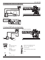
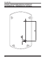
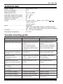
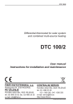
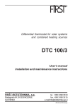
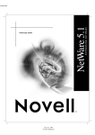
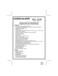
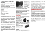
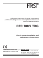
Differential thermostat for solar systems and
combined heating sources and regulation of burner or
electric heating element
DTC 100/2 TDG
User’s manual Installation and
maintenance instructions
FIRŠT-ROTOTEHNIKA, s.p. PE VELENJE
Radegunda 54, 3330 MOZIRJE
Koroška cesta 56a, 3320 VELENJE
tel. 03/ 898 35 00, fax. 03/ 898 35 35
www.first.si, e-mail: [email protected]
ID-2605-01-DTC100-2TDG-ang.indd
DTC 100/2 TDG
Dear custumer
Congratulations
You have bought a DTC 100/2TDG differential thermostat, manufactured according to the
latest quality and safety standards. It is made according to the state of art and efficiently
utilizes solar energy or alternative sources for domestic water heating. We are convinced
that the use of our product will satisfy your needs too and help you to save your money.
Thanks for your confidence FIRŠT Rototehnika
The set consist of:
- Differential thermostat DTC 100/2TDG
- T1 collector sensor with silicone conductor
- T2 hot water tank sensor with PVC conductor
- Clip for sensor fastening with fixing springs
- Instruction for use
- Warranty certificate
In case any of above specified elements are missing or are defective require your dealer
to replace it.
Read the instructions carefully in order to be able to make use of all advantages of the
product.
! WARNING !
All examples listed in the instructions are merely indicative. The manufacturer accepts
no responsibility for incorrect hydraulic connection of machine part of installations should
comply with all safety regulations defined by law and the rules.
We reserve the right to modify the instructions and the technical data of the product
without prior notice
2
DTC 100/2 TDG
GENERAL
DTC 100/2TDG is a single differential thermostat featuring temperature display, designed
for domestic water heating from one heating source (solar collectors, boilers, heat,
pumps,...) The thermostat controls pump or motor actuated ball valve (EMV 110...) and
burner or electric heating element.
Parameter settings:
1. Regulation of maximum temperature in hot water tank from 10° to 90°C.
This temperature is defined by T2 sensor witch is generally mounted in upper third of
heat exchanger.
2. Regulation of difference for higher exchanger from 2K to 15K
With this parameter you define how much the value of the source temperature (collector,
boiler,...) should exceed the temperature of water around the exchanger in hot water tank,
that the regulator activates the pump or opens motor actuated valve. The difference is set
in relation to the volume of heat losses of the system which depend on lengths of pipelines
from source to hot water tank and on pipeline insulation. Built-in digital display enables
prompt reading of the temperatures of individual sensors and of all set values as well.
3. It has built in counter of pump working hours.
OPERATION
DTC 100/2TDG single differential thermostat measures the temperature of two heating
sources (collectors, boiler ...) and in user (hot water tank).
Heating effect is provided, when heating source temperature is higher than the temperature
of the user (water in hot water tank). Consequently minimum adjustable difference is 2°
(factory set to 5°). When the temperature of the source (collector) exceeds the temperature
around the user for pre-set difference it switches ON the pump and opens motor actuated
ball valve.
The thermostat switches OFF the pump if pre-set temperature is reached in hot water
tank (adjustable from 10° to 90°C).
If boiler or electric heating element is connected, the thermostat can switch it ON. When
is heating required, thermostat switches ON heating source. When the temperature of
the source (collector) exceeds the temperature around the user for pre-set difference the
thermostat switches ON the pump and opens motor actuated ball valve.
If any sensor is faulty (interrupted or short circuited), thermostat immediately switches
off the pump and signalizes the condition on the display (“Er1” - sensor interrupted, “Er2
- sensor short circuited).
3
DTC 100/2 TDG
INSTALLATION OF THERMOSTAT
Install the thermostat on hot water tank chasing or close to it. Do not install it under the
pipe fittings or valves due to possible water dripping on its housing.
Sensor installation
Sensor Installation in Collector or boiler (KF)
Install sensor with silicon (red) isolation!
Install it as immersion sensor in collecting pipe at the top of the collectors in provided
sleeve (picture A).
Connect it on terminals 1 and 2. Recommended type of cable: J-Y (St) 1x2x0,6.
For cables longer than 15m we recommend over-voltage protection with CDR resistor
(picture B)
flow
direction
T-piece 1/2”
pipe1/2”
pict: A
VDR resistor thermo-shrinkable
tubes
extension
conductor
sensor conductor
pict: B
Sensor installation in hot water tank.
Install sensor with PVC (gray) isolation!
Install T2 sensor to provided place in hot water tank or on hot water tank
wall under isolation as contact sensor in lower part of exchanger. When sensor
is mounted as contact one, we recommend coating it with heat conducting
paste or liquid metal.
In special purpose vertical or
horizontal tube (sensor should be
protected against accidental
extraction).
On hot water tank with clip, wire and
spring strip (use paste for better heat
transmission).
In special purpose side
tube (protect against
extraction).
Warning
By mounting sensors must be assured suitable mechanical protection and sensors
must be protected against atmosphere influence.
4
DTC 100/2 TDG
Testing sensors
For testing purposes you can simulate temperatures with resistors.
Sensor dimensions:
l
l=1,5m sensor BSF1, PVC (gray)
l=2m sensor KF, silicon (red)
ELECTRICAL CONNECTION
Before opening unplug power supply! Only qualified person can maintain
the thermostat.
Grounding wires should be
connected to special screw
BURNER
terminals situated on right side of
terminal strips.
The thermostat is designed for
fixed instalation. When performing
electric instalation, an element
should be inserted which enables at
least 3 mm separation of thermostat
from the mains (switch or socket). Prir to
each intervention in the thermostat, first
disconnect it from the mains.
Terminal
Connection
1,2
sensor T1 - heating source
3,4
sensor T2 - hot water tank
11
N - neutral conductor
12
L - phase - boiler control 1(1)A, 250V , 50Hz
13
N - neutral conductor
14
L - phase - pump control 1(1)A, 250V , 50Hz
15
L - phase - connector for mains 230V , 50Hz
16
N - neutral conductor for mains
5
DTC 100/2 TDG
CONTROL PANEL
1.........Regulation of maximum required temperature in hot water tank (10°-90°)
2.........Operation switch for operation mode selector (OFF, AUTO, ON)
3.........Display
4.........Control light for pump operation
5.........Control light for burner operation
6.........Key for adjustment of thermostat difference
7.........Key for max. required temperature display or difference decreasing
8.........Key for collector temperature display or difference increasing
USE OF SELECTOR SWITCH FOR MANUAL CONTROL
OFF Irrespective of temperature values, the pump and burner are off.
AUTO Automatic operation of thermostat (normal operation)
ON Irrespective of temperature values, the pump and burner are on.
OFF and ON positions are used only for operation tests. OFF position does not
enables galvanic separation from mains.
Temperature display:
During normal use display shows “T2” witch is the temparature of water
in hot water tank.
If you press “T1” key the display shows the temparature in collectors
(T1).
Temparature remains displayed until the key is presed.
If you press “T2max” key the display shows the maximum temparature
set with the knob (1).
6
DTC 100/2 TDG
TEMPERATURE SETTING OF HOT WATER TANK
You can set maximum water temperature of hot water tank (from 10° to 90°) with the right
key. When the temperature is reached, the thermostat deactivate the pump regardless the
temperature of heating source. If hot water is used by the appliance with limited maximum
temperature of inflow, this setting is very useful.
NOTE!
Regulator reaction time is 5 sec. max., therefore after each change of knob (1)
position you must wait 5 sec. to see the change on the display
Difference setting:
The difference is set with three keys, situated under the display. Press “dT”
key and on display “d” and “pre-set difference” appear. With “ê" and "é"
keys decrease or increase the pre-set value. When new required value is
entered, press once again the "dT" key to store this new value. It will remain
stored also if thermostat is disconnected from the mains.
When you set the required difference, press key T1 and hold it!
On the display appears P.r. and hold down the key (approximately 3s),
until the sign P.r. disappear and on display appears the temperature T1.
Then release the key.
If you release the key too soon, entered value is not effective.
COUNTER OF PUMP WORKING HOURS
Press all three keys together and hold them about 5sec, on display appears
value of pump working hours.
RESETTING COUNTER OF PUMP WORKING HOURS
Press the middle key and hold it about 10sec until reset of the counter. On
display apears value 0.
7
DTC 100/2 TDG
Examples:
1. Heating DHWT (domestic hot water tank) with solar collectors
Electrical connection
2. Heating DHWT with solar collectors
To prevent thermo circulation of water at night time, we recommend use of motor
actuated ball valve. More on last page.
Electrical connection
3. Heating DHWT with solid fuel boiler.
Electrical connection
8
DTC 100/2 TDG
4. Heating DHWT with oil or gas boiler.
Electrical connection
Boiler control:
5. Heating DHWT with electrical heater.
Electrical connection
Legend:
DTC
Differential thermostat
DTC 100/2 TDG
T1, T2
Sensors
T1 - colector sensor
T2 - DHWT sensor
Electric motor actuated ball valve
EMV 110 .. series 602, 603
Electrical heater
Safety thermostat of electric heater
Relay
P
Pump
Non return valve
9
DTC 100/2 TDG
HOLES FOR EASIER INSTALLATION OF DIFFERENTIAL THERMOSTAT ON WALL
10
DTC 100/2 TDG
Technical data
Supply voltage:................................ 230V, 50Hz +/-10%
Power consumption......................... 4 VA
Type of thermostat........................... P
Measurement area.......................... -40°C do 160°C
Adjustable temperature range......... 10°C - 90°C
Adjustable difference settings.......... 2K - 15K
Hysteresis of difference................... 1K - 2K
Number of sensors.......................... 2
Output: . .......................................... 2x relay: 230V , 50Hz, 1(1)A, SPST
:
- pump control
- burner control
Inputi: . ............................................ 2x sensors
- BSF1- PVC (gray) cable, lenght 1,5m (DHWT sensor)
- KF - Silicon (red) cable, lenght 2m (collector sensor)
Humidity:.......................................... 5% - 70% (non condensed)
Storehouse temperature: . .............. 0°C-70°C
Trouble-shooting guide
TROUBLE
POSSIBLE FAILURE
REMEDY
Thermostat inoperative
Plug not connected
Connect plug in socket
Water cools down during night
-Selector switch not in AUTO
position
-One of retaining valves
of the system inoperative
(enables thermosiohon water
circulation)
-Set the switch to AUTO
position
-Check machine installation
We recommend installation of
motor actuated ball valve
When pump is active,
unplesant noise in installation
is heard
Retaining valve makes noise
(weak spring)
Replace nonreturn valve with
motor actuated ball valve
Irrespective of the
temperatures, pump is
inoperative
- Selector switch (2) in position
»OFF« - “T2max.”(1) set too
low(under 20°C)
- Set selector switch (2) to
AUTO position
- Increase T2max
Irrespective of the temp.,
pump is continuosly switched
on.
Selector switch (2) in “ON”
position
Set the switch to AUTO
position
When “T1” key(7) is pressed
Er1 appears
T1 sensor is interrupted
Check T1 senzor
When “T1” (7)key is pressed
Er2 appears
T1 sensor is short circuited
Check T1 senzor
Er1 is shown on display
T2 sensor is interrupted
Check T2 senzor
Er2 is shown on display
T2 sensor is short circuited
Check T2 senzor
Control light of the pump is on,
but the pump is inoperative
Pump bloked or cable of the Chek the pump and connection
pump interrupted
to regulator
11
DTC 100/2 TDG
Advantages of motor actuated ball valves of EMV110..
series with incorporated relay module for solar heating systems
In solar heating systems motor actuated ball valves can prevent various
inconveniences.
- Effectively prevent hydraulic shocks in systems as they require 30 seconds for complete
opening.
- Due to their shape they do not impede the flow.
- Springs are not included, therefore noise does not appear.
- When closed, 100% sealing is guaranteed.
- They have an output for pump up to 1000 W in open position, therefore they do not
present a hydraulic load for pump in closed position. They enable pump switching on
only in completely open position.
- Due to installed RELAY module they enable control with make contact only.
- If during closing or opening process impurities enter in valve, which could block it, the
valve stops and immediately afterwards continues with opening or closing process in
opposite direction, so that water flow can rinse the impurities up to cleaning net (antiblocking system).
EMV 110 603/4230
12
EMV 110 602/4230