1
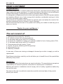
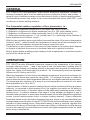
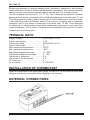
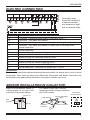
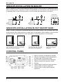
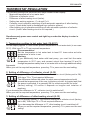
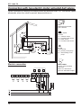
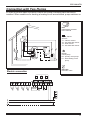
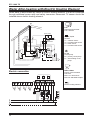
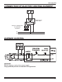
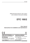
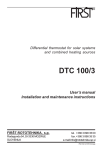
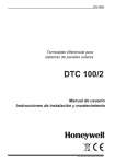
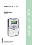
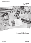
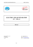
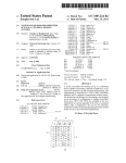
DTC 100/4 TD Differential thermostat for regulation of two heating circuits in combination of solar and classic heating with temperature display and regulation of burner or electric heating element DTC 100/4 TD User’s manual Installation and maintenance instructions FIRŠT-ROTOTEHNIKA, s.p. PE VELENJE Radegunda 54, 3330 MOZIRJE Koroška cesta 56a, 3320 VELENJE tel. 03/ 898 35 00, fax. 03/ 898 35 35 www.first.si, e-mail: [email protected] 1 ID-2106-13-DTC100-4TD-Honeywell-170039 ID-2605-01-DTC100-2TDG-ang.indd DTC 100/4 TD DEAR CUSTOMER Congratulations ! You have bought a DTC 100/4TD differential thermostat, manufactured according to the latest quality and safety standards. It is made according to the state of art and efficiently utilises solar energy or alternative sources for domestic water heating. It is designed in compliance with strict criteria and requirements of West European markets and enables efficient use of solar energy which enables considerable savings of other sources for domestic water heating. Our products are available in the markets for several years and satisfy the needs of de manding customers from hot Greece to north Germany. We are convinced that the use of our product will satisfy your needs too and help you to save your money. Thanks for your confidence ! The set consist of: 1. Differential thermostat DTC 100/4TD 2. T1 collector sensor with silicone conductor 3. T2 hot water tank sensor with PVC conductor 4. T3 sensor for installation in boiler or to upstream conduit in front of mixing valve (PVC) 5. T4 hot water tank sensor with PVC conductor 6. Fixing screws with wall inserts (2 pcs) 7. Clip for T4 sensor fastening with fixing springs 8. Instructions for use 9. Warranty certificate In case any of these are missing or damaged, demand your seller to supply you with a replacement. Read these instructions carefully, as this will allow you to benefit from all the possibilities offered by this product. WARNING ! All examples listed in the instructions are merely indicative. The manufacturer accepts no responsibility for incorrect hydraulic connection of machine part of installation. Machine and electric installations should comply with all safety regulations defined by law and the rules. We reserve the right to modify the instructions and the technical data of the product without prior notice 2 DTC 100/4 TD GENERAL DTC 100/4TD is a microprocessor aided double differential thermostat, designed for heating of domestic water from two heating sources (collectors, boilers, heat pumps,...), using its logic of additional energy source switching on (boiler of central heating system). The thermostat controls two pumps or two motors actuated ball valves (EMV 800...) and one burner or electric heating element. The thermostat enables regulation of four parameters, i.e.: 1. Regulation of maximum temperature in hot water tank from 10 to 90°C. 2. Regulation of difference for higher exchanger from 2 to 15K (after-heating circuit) 3. Regulation of difference for lower exchanger from 2 to 15K (collector circuit) 4. Setting two working regimes - C.n.b (normal) and C.d.t. (switching off the limitation of boiler temperature for collector circuit). With first two regulation options you define how much the value of the source temperature (collector, boiler,...) should exceed the temperature of water around the exchanger in hot water tank, that the regulator activates the pump or opens the valve. The difference is set in relation to the volume of heat losses of the system which depend on lenghts of pipelines from source to hot water tank and on pipeline insulation. Built-in digital display enables prompt reading of the temperatures of individual sensors and of all set values as well. OPERATION: DTC 100/4TD double differential thermostat measures the temperature of two heating sources (collectors, boiler, ...) and of two spots in user (hot water tank). Heating effect is provided, when heating unit (heating element in hot water tank) exceeds the temperature of the user (water in hot water tank) for at least 3 - 5K. Consequently minimum adjustable difference is 2K (factory set to 5K). When the temperature of the source exceeds the temperature around the exchanger for at least 5K, the thermostat opens the valve (EMV...) or activates the pump; it closes the valve or stops the pump, when temperature difference is one degree lower than pre-set value. The thermostat also switches off a pump if pre-set temperature is reached in hot water tank (adjustable from 10 to 90°C). If gas flow boiler, oil boiler or electric heating element (which is switched off during summer seasons), is connected to after-heating circuit, the regulator can switch on the boiler by means of the third output, if domestic water is to be additionally heated by means of afterheating circuit. In summer seasons a few days of cloudy weather can appear or use of domestic water increases. In such cases domestic water is to be after-heated from additional source (central heating system boiler or electric heating element). Classic differential thermostat would require hot boiler throughout the year, which is not recommended from ecological and economic point of view. DTC 100/4TD, with its third additional output, enables activation of after-heating source. When after-heating of water is required, regulator first switches on the burner of the boiler and when the condition of difference for after-heating circuit is also assured (pre-set difference of boiler has higher temperature than hot water tank), pump is switched on. 3 DTC 100/4 TD When pump operates for primary heating circuit (collectors), operation of after-heating circuit and burner of boiler or electric heating element is prevented. This assures maximum energy savings during summer seasons and is also the main role of solar systems. The set comprises four sensors (T1, T2, T3, T4). Two of them are mounted into individual heating sources and two into upper half of individual exchangers in hot water tank. T1 and T2 are designed for primary (main) heating circuit, which heats entire quantity of water in hot water tank (lower exchanger), where T1 is a sensor of heating source (generally collectors) and T2 is a sensor in lower part of hot water tank. T3 and T4 are designed for additional, i.e. after-heating circuit which additionally heats water in hot water tank (upper exchanger). T3 is a sensor of heating source (generally boiler) and T4 is a sensor in upper part of hot water tank. TEHNICAL DATA: Supply voltage........................................ 230V, 50Hz +/- 10% Power consumption................................ 4 VA Pump relay rating................................... 3A/230VAC cos 0.6 Type of thermostat.................................. P Max. measured temperature.................. 180°C Min. measured temperature................... -20°C Adjustable temperature range................ 10 - 90°C Temperature difference settings............. 2 - 15K Hysteresis of difference.......................... 2°K Hysteresis of the thermostat................... 3°K Nr. of sensors......................................... 4 Nr. of outputs.......................................... 3 (230 VAC) INSTALLATION OF THERMOSTAT: Install the thermostat on hot water tank casing or close to it. Do not mount it under pipe fittings or valves due to possible water dripping on its housing. EXTERNAL CONNECTIONS: 4 DTC 100/4 TD ELECTRIC CONNECTION: Grounding wires should be connected to special terminal pins situated on right side of terminal strips. BOILER TERMINAL 1,2 3,4 5,6 7,8 9 10 11 12 13 14 15 16 CONNECTION T1 sensor – heating source sensor (collectors, boiler…) T2 sensor – hot water tank sensor T3 sensor – heating source sensor for higher heating circuit (boiler) T4 sensor – hot water tank sensor in upper part of hot water tank neutral conductor neutral conductor phase for boiler (burner) switching on neutral conductor phase of pump for secondary heating circuit neutral conductor phase of pump for collector heating circuit phase connector for mains 230V, 50 Hz neutral conductor - connector for mains 230 V, 50 Hz WARNING: Boiler control should be performed behind the main switch for burner but in front of boiler thermostat. Care must be taken that differential thermostat and boiler connection are performed at the same phase otherwise inter-phase contact can occur. SENSOR INSTALLATION IN COLLECTOR: Install it as immersion sensor in collecting pipe at the top of the collectors in provided sleeve T piece 1/2” For cables longer than 15m we recommend over-voltage protection with VDR resistor. VDR resistor flow direction pipe 1/2” extension conductor Thermo-shrinkable tubes Connection to terminal pins sensor conductor 5 DTC 100/4 TD Sensor Installation in Boiler: Built T3 sensor in a boiler as immersion sensor infront of mixing valve in upstream flow or next to boiler sensor in a sleeve. If this is not possible you can mount it as contact sensor in upstream flow in front of mixing valve. In such a case we recommend to isolate it. Connection to terminal pins Sensors Installation in Hot Water Tank: Install T2 and T4 sensors to provided place in hot water tank or on hot water tank wall under isolation as contact sensor in upper part of exchanger. When sensor is mounted as contact one we recommend to coat it with heat conducting paste or liquid metal. In special purpose vertical or horizontal tube (sensor should be protected against accidental extraction). On hot water tank with clip, wire and spring strip (use paste for better heat transmission). In special purpose side tube (protect against extraction). CONTROL PANEL 1 2 3 4 5 6 7 8 6 Key for collector temperature display Key for the display of the temperature in lower part of hot water tank Key for boiler temperature displayed Selector switch for manual control Display Control light of collector pump operation Control light of burner operation Control light of after-heating pump operation DTC 100/4 TD THERMOSTAT REGULATION The following settings are performed with keys situated under display: - Maximum temperature in hot water tank. - Difference of collector circuit. - Difference of after-heating circuit (boiler). - Setting two working regimes - C.n.b and C.d.t. - Collector circuit operation switching off with automatic operation of after-heating circuit. (Used when liquid is discharged from collector system.) - After-heating circuit operation switching off with automatic operation of collector circuit. (Used if after-heating circuit is not required.) Simultaneously press once central and right keys under the display to enter in set-up meni 1. Temperature setting in hot water tank (10-90°C) On the display appear “b” and current pre-set temperature of hot water tank (in our case 55°C). With keys T2 in T3 set required temperature. Recommendation: Set the temperature in hot water tank to least 10° lower value as boiler temperature in boiler is set. Warning: If you additionally heat water with heat pump, you must limit the water temperature to 55°C max. and connect output from terminal 12 and 14 through temperature safety fuse in hot water tank or through additional safety thermostat. When you set the required temperature, press key T1 to pass over the next setting. 2. Setting of difference of collector circuit (0-15) On the display appear “C” and current difference of collector circuit (factory set to 5K). With keys T2 in T3 set required difference. The difference defines the value for which source temperature should exceed the temperature of the user (collectors or boiler: hot water tank) that the pump is activated. It is generally 5K for collectors and 8K for boiler (factory setting). Of course it depends on lengths and isolation of pipelines. If you decrease the difference to “0”, collector circuit is switched off. When you set the required temperature, press key T1 to pass over the next setting. 3. Setting of difference of after-heating circuit (0-15) On the display appear “P” and current difference of collector circuit (factory set to 8K). With keys T2 in T3 set required difference. If you decrease the difference to “0”, after-heating circuit is switched off. When you set the required temperature, press key T1 to pass over the next setting. 7 DTC 100/4 TD 4. Setting the working regimes - C.n.b and C.d.t. On the display appears signs “C.n.b.” or “C.d.t.” Regime: C.n.b. Normal state of thermostat. Limitations of temperatures valid for collector circuit and after-heating circuit. This regime must be used in systems with heat pump. Regime: C.d.t. Thermostat heats domestic water from collector circuit irrespective of setting of max. temperature in boiler (no limitation of max. temperature of the boiler for collector circuit). Choose that regime in case, that you want to use max. energy of collector and the crossing temperature of the boiler will not damage no one of connected consumer of hot water. With keys T2 in T3 set required regime. When you set the required regime, press key T1 and hold it! On the display appears P.r. and hold down the key (approximately 3s), until the sign P.r. disappears and on display appears the temperature T1 (temperature of collector circuit). Now release the key. If you release the key too soon, entered values are not effective. We mentioned before, that we have the possibility to disconnect the collector circuit and after-heating circuit. For such step we decide in following cases: Disconnection of Collector Circuit Operation It is used in cases of mechanical faults of collector system, which requires draining of liquid (water) from collector system, but after-heating circuit should operate in automatic mode. Disconnection is useful also in systems where water is discharged from collectors during winter, which prevents “dry operation” of the pump. The procedure of disconnection is described in point 2 - set the parameter C to value 0. When you want again connection of the collector circuit, set the parameter C to value different from 0 (factory set to 5K). Disconnection of After-heating Circuit Operation It is used in cases of mechanical faults of after-heating system which requires draining of liquid (water) from the system but collector circuit should operate in automatic mode. It disconnects after-heating pump operation as well as burner (or electric heating element) switching on. The procedure of disconnection is described in point 3 - set the parameter P to value 0. When you want again connection of the after-heating circuit, set the parameter P to value different from 0 (factory set to 8K). 8 DTC 100/4 TD WARNING! If T2 and T3 keys are simultaneously pressed, you enter set-up menu. If in about 1 minute the values are not changed, regulator automatically leaves this menu (it shows T4 tem perature in hot water tank). If you have changed the values and you haven’t left the set-up menu, entered values are not effective. Temperature Display: During normal use display shows “T4” temperature, which is the temperature of water in upper part of hot water tank. If you press “T1” key, the display shows temperature in collectors (T1). Temperature remains displayed until the key is pressed. If you press “T2” key the display shows temperature of lower part of hot water tank (T2). Temperature remains displayed until the key is pressed. If you press “T3” key, the display shows temperature in boiler (T3). Temperature remains displayed until the key is pressed. WARNING! Regulator reaction time is 5 sec. max., therefore after each change of temperature you must wait for 5 sec. to see the change on the display. Display of Sensor Errors: Errors of sensors (short circuit, interrupted sensor) are listed on the display. If the sensor is short circuited the display shows “Er2” and if it is interrupted “Er1”. For T4 sensor this is permanently shown and for other sensors you must press “T1”, “T2” or “T3” keys. If T1 or T2 sensor is faulty, collector heating circuit is inoperative and after-heating circuit operates normally in automatic mode. If T3 or T4 sensor is faulty, after-heating circuit is inoperative and collector circuit operates normally in automatic mode. USE OF SELECTOR SWITCH FOR MANUAL CONTROL ON1 Main heating circuit operates continuously. Max. temperature is no limited. AUTO Automatic operation of thermostat (normal operation). OFF Both pumps are switched off irrespective of temperature values. ON2 After-heating circuit continuously operates. Max. temperatures are not limited. WARNING! ON1, ON2 and OFF positions are used only for operation tests of pumps and mainte nance disconnection of pump operation when charging and venting the system, but not during normal operation. OFF position does not enable galvanic separation from mains. When replacing the pump, disconnect supply voltage! 9 DTC 100/4 TD Connection with two electric motor actuated ball valves When conditions for heating of a heating circuit are achieved, EMV110...800 series, opens afterwards, when the valve is opened, pump switches on. DTC Differential thermostat DTC 100/4TD T1, T2, T3, T4 Sensors T1 - collector sensor T2 - hot water tank sensor T3 - boiler sensor T4 - hot water tank sensor P1, P2 Circuit pump P2 - primary circuit pump P1 - after-heating circuit pump Electric connection EMV1, EMV2 Electric motor actuated ball valve: EMV 110..4230 series EMV 110..3230 series compact BOILER 10 DTC 100/4 TD Connection with Two Pumps In order to prevent water circulation, behind the pump a retaining valve should be installed. When conditions for heating a heating circuit are achieved, pump switches on. DTC Differential thermostat DTC 100/4TD T1, T2, T3, T4 Sensors T1 - collector sensor T2 - hot water tank sensor T3 - boiler sensor T4 - hot water tank sensor P1, P2 Circuit pump P2 - primary circuit pump P1 - after-heating circuit pump RV1, RV2 Nonreturn valve Electric connection BOILER 11 DTC 100/4 TD Water After-heating with Electric Heating Element When water is after-heated by means of electric heating element, it must be connected through additional power relay and safety immersion thermostat. T4 sensor should be installed above electric heating element. DTC Differential thermostat DTC 100/4TD power relay safety thermostat T1, T2, T3, T4 Sensors T1 - collector sensor T2 - hot water tank sensor T3 - boiler sensor T4 - hot water tank sensor P1, P2 Circuit pump P2 - primary circuit pump P1 - after-heating circuit pump Electric connection EMV1, EMV2 Electric motor actuated ball valve: EMV 110..4230 series EMV 110..3230 series compact electric heating element 12 DTC 100/4 TD CONNECTION OF ELECTRIC HEATING ELEMENT POWER RELAY 230V, 50Hz SAFETY THERMOSTAT OF HEATING ELEMENT EL. HEATER BURNER CONTROL WARNING: Before opening, unplug from power supply. Only qualified person can maintain the apparatus. 13 DTC 100/4 TD HOLES FOR EASIER INSTALLATION OF DIFFERENTIAL THERMOSTAT ON WALL 14 DTC 100/4 TD Trouble-shooting guide TROUBLE Thermostat inoperative Water cools down during night When pumps are active, unpleasant noise in installation is heard Irrespective of the temperatures, all pumps are inoperative Irrespective of the temp., collector pump is continuosly switched on and after-heating pump is inoperative Irrespective of the temp., after-heating pump is continously switched on and collector pump is inoperative Collector pump operates normally and after heating pump not After-heating pump operates normally and collector pump not Control light of individual pump is on, but the pump is inoperative When “T1” key is pressed Er1 appears When “T1” key is pressed Er2 appears When “T2” key is pressed Er1 appears When “T2” key is pressed Er2 appears When “T3” key is pressed Er1 appears When “T3” key is pressed Er2 appears Er1 is shown on display Er2 is shown on display POSSIBLE FAILURE Plug not connected -Selector switch not in AUTO position -One of retaining valves of the system inoperative (enables thermosiohon water circulation) Retaining valve makes noise (weak spring) REMEDY Connect plug in socket -Set the switch to AUTO position-Check machine installation. We recommend installation of motor actuated ball valve “EMV110 800/230..” Selector switch in “ON2” position Set selector switch to AUTO position After-heating circuit disconnected Connect after-heating circuit See: Settings Replace nonreturn valve with motor actuated ball valve “EMV110 800/230..” Selector switch in position Set selector switch to AUTO “OFF” position Increase max. Temperature limit of hot water temperature in hot water tank tank too low (see: Temperature regulation in hot water tank) Selector switch in “ON1” Set the switch to AUTO position position Collector circuit disconnected Connect collector circuit See: Settings Pump blocked or cable of the pump interrupted Check the pump and connection to regulator T1 sensor is interrupted Check T1 sensor T1 sensor is short circuited Check T1 sensor T2 sensor is interrupted Check T2 sensor T2 sensor is short circuited Check T2 sensor T3 sensor is interrupted Check T3 sensor T3 sensor is short circuited Check T3 sensor T4 sensor is interrupted T4 sensor is short circuited Check T4 sensor Check T4 sensor 15 DTC 100/4 TD Advantages of motor actuated ball valves of EMV110..series with incorporated relay module for solar heating systems In solar heating systems motor actuated ball valves can prevent various inconveniences. • Effectively prevent hydraulic shocks in systems as they require 30 seconds for complete opening. • Due to their shape they do not impede the flow. • Springs are not included, therefore noise does not appear. • When closed, 100% sealing is guaranteed. • They have an output for pump up to 100 W in open position, therefore they do not present a hydraulic load for pump in closed position. They enable pump switching on only in completely open position. • Due to installed RELAY module they enable control with make contact only. • If during closing or opening process impurities enter in valve, which could block it, the valve stops and immediately afterwards continues with opening or closing process in opposite direction, so that water flow can rinse the impurities up to cleaning net (antiblocking system). 16