1
ATH 400M / ATH 1000M
Maglev hybrid turbomolecular pump
Welcome
Dear Customer,
You have just purchased an
Alcatel maglev hybrid turbo
pump.
We would like to thank you
and are proud to count you
as one of our customers.
Edition 07 - January 02
This product has benefited
from Alcatel’s many years
of experience in the field of
turbomolecular pump
design.
In order to ensure the best
possible performance of the
equipment and your
complete satisfaction in
using it, we advise you to
read this manual carefully
before any intervention on
your pump and to pay
particular attention to the
equipment installation and
start-up section.
MANUAL REFERENCE : 101 688
EDITION : 07 - JANUARY 2002
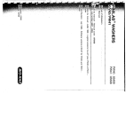
APPLICATIONS:
SEMICONDUCTOR APPLICATIONS
Plasma etching, Ion implantation, Sputtering,
Plasma deposition.
OTHERS APPLICATIONS
Electron microscopes, Surface analysis,
Research and development, High energy physics,
Space simulation, Accelerators.
ADVANTAGES:
High throughput - Quiet and clean vacuum - Corrosion
proof - High MTBF - Minimum size, volume and weight Smart and compact electronic controller - Reliability Maintenance free - Battery free - Easy integration.
Alcatel - High Vacuum Technology - User’s Manual ATH 400M / ATH 1000M
1/1
Contents
User’s Manual
ATH 400M / ATH 1000M
Introduction
■ Contents chapter A . . . . . . . . . . . . . . . . . .
■ Introduction to the ATH 400M/ATH 1000M
and their associated ACT controller . . . . . . . . ■ A 10
■ The pump operating principle . . . . . . . . . . . . ■ A 20
■ The different versions . . . . . . . . . . . . . . . . . ■ A 30
■ ACT 600M and ACT 1000M controllers . . . . . ■ A 40
■ The accessories . . . . . . . . . . . . . . . . . . . . . ■ A 50
■ The technical characteristics . . . . . . . . . . . . . ■ A 60
Edition 07 - January 02
Start-up
MANUAL
REFERENCE
■
■
■
■
■
■
■
■
■
■
■
■
■
Contents chapter B . . . . . . . . . . . . . . . . . . .
Safety instructions related to installation . . . . . ■ B 10
Unpacking and storage . . . . . . . . . . . . . . . . ■ B 20
Pump connections to an installation . . . . . . . . ■ B 30
Emergency braking valve connection . . . . . . . ■ B 40
Nitrogen purge device connection . . . . . . . . . ■ B 50
Water cooling connection . . . . . . . . . . . . . . ■ B 60
Heating band connection . . . . . . . . . . . . . . . ■ B 70
Electrical connections . . . . . . . . . . . . . . . . . ■ B 80
«Dry contacts» relay wiring . . . . . . . . . . . . . ■ B 90
«Remote Control» connector wiring . . . . . . . . ■ B 100
RS 232 or RS 485 serial link wiring. . . . . . . . ■ B 110
Detailed description of RS commands . . . . . . . ■ B 120
: 101 688
EDITION : 07 - January 02
Alcatel - High Vacuum Technology - ATH 400M / ATH 1000M User’s Manual
1/3
Contents
User’s Manual
ATH 400M / ATH 1000M
Operation
■
■
■
■
■
Contents chapter C. . . . . . . . . . . . . . . . . . .
■
■
■
■
■
■
■
■
■
■
■
■
■
■
■
■
■
■
Contents chapter D. . . . . . . . . . . . . . . . . . .
Safety instructions related to operation . . . . . . ■ C 10
Controller start-up . . . . . . . . . . . . . . . . . . . ■ C 20
Configuring the controller for the application . . ■ C 30
Controlling the pump using the controller
front panel . . . . . . . . . . . . . . . . . . . . . . . . ■ C 40
■ Pump operation in a pumping application . . . . ■ C 50
■ «Ext. safety» contact operation . . . . . . . . . . . ■ C 60
MANUAL
REFERENCE
Safety instructions related to maintenance. . . . . . ■ D 10
Diagnosis and troubleshooting . . . . . . . . . . . ■ D 20
Screen blocked on a display . . . . . . . . . . . . ■ D 30
D01 : POWER OVERHEAT. . . . . . . . . . . . . ■ D 40
D02 : MOTOR CONTROL OVERHEAT . . . . . ■ D 50
D03 : MOTOR CONTROL OVERHEAT . . . . . ■ D 60
D04 : HALL SENSOR . . . . . . . . . . . . . . . ■ D 70
D05 : OVERCURRENT OR SENSOR . . . . . . ■ D 80
D06 : EXTERNAL SAFETY . . . . . . . . . . . . ■ D 90
D11 : MAG SUSPENSION . . . . . . . . . . . . ■ D 100
D12 : POWER . . . . . . . . . . . . . . . . . . . . . ■ D 110
D13 : POWER OVERCURRENT . . . . . . . . . ■ D 120
D14 - D15 - D16 - D17 - D18 . . . . . . . ■ D 130
D21 : PUMP OVERHEAT-1 . . . . . . . . . . . . ■ D 140
D21 : PUMP OVERHEAT-2 . . . . . . . . . . . . ■ D 150
D22 : CONTROLLER OVERHEAT . . . . . . . . ■ D 160
D23 : HOT PUMP . . . . . . . . . . . . . . . . . . ■ D 170
: 101 688
EDITION : 07 - January 02
2/3
Alcatel - High Vacuum Technology - ATH 400M / ATH 1000M User’s Manual
Edition 07 - January 02
Maintenance
Contents
User’s Manual
ATH 400M / ATH 1000M
Maintenance
(continued)
■
■
■
■
■
■
■
■
■
■
■
D24 : BEARING MUST BE CHANGED . . . . ■ D 180
D25 : TEMP SENSOR-1 . . . . . . . . . . . . . . ■ D 190
D26 : NO CONNECT . . . . . . . . . . . . . . . . ■ D 200
D27 : DATE AND TIME . . . . . . . . . . . . . . ■ D 210
D28 : DISABLE WRITE . . . . . . . . . . . . . . ■ D 220
D29 : INPUT POWER . . . . . . . . . . . . . . . ■ D 230
D30 : EEPROM CHECKSUM . . . . . . . . . . . ■ D 240*
D31 : CODING . . . . . . . . . . . . . . . . . . . . ■ D 250
D32 : NO CABLE INSIDE . . . . . . . . . . . . ■ D 260*
D38 (37) : TEMP SENSOR-2 . . . . . . . . . ■ D 270
Default not indicated by the controller. . . . . . . ■ D 280
■ Contents chapter F . . . . . . . . . . . . . . . . . . .
■ First level maintenance parts. . . . . . . . . . . . . ■ F 10
Appendix
■ Contents chapter G . . . . . . . . . . . . . . . . . .
■ Pumping curves ATH 400M . . . . . . . . . . . . . ■ G 10
■ Pumping curves ATH 1000M . . . . . . . . . . . . ■ G 20
Edition 07 - January 02
Maintenance
Components
MANUAL
REFERENCE
: 101 688
EDITION : 07 - January 02
* These chapters are reserved for the Customer Service.
Alcatel - High Vacuum Technology - ATH 400M / ATH 1000M User’s Manual
3/3
A 10
Introduction to the ATH 400M/ATH 1000M
and their associated ACT controllers
2 magnetically levitated
hybrid turbo pumps
ATH 400M
and ATH 1000M
Five active axes
ACTIDYNE® Maglev
bearings type (S2M Patent)
Rotor position control in
5 directions.
Edition 05 - October 96
Automatic balancing system
Lowest possible levels of
noise and vibration.
Compensation for any
imbalance of the rotor.
Inverted dynamic seal
High compression ratio.
ATH 400MT
ATH 1000MT
Exclusive protection.
Inert gas purge
Eliminate corrosion of
the motor and magnetic
bearing coils.
Maintenance free
Battery free
In case of a power failure,
the pump motor acts like
a generator to transform
the rotor energy into
Integral heater band
Maintaining the pumps internal surface up to 75°C to
prevent the condensation effect.
Temperature regulated by the ACT controllers.
Alcatel - High Vacuum Technology - User’s Manual ATH 400M / ATH 1000M
1/2
A 10
Introduction to the ATH 400M/ATH 1000M
and their associated ACT controllers
ACT 600M and
ACT 1000M controllers
The new generation of
ACT controller family
Especially designed for maglev turbopumps
Light and small controllers.
Battery free.
Modern pump monitoring
Monitoring of testing and troubleshooting parameters;
RS 232/485 serial links;
Automatic power supply detection from 85 to 265 V,
48/63 Hz single phase.
Large range of interface
Dry contacts interface for status signals and optocoupled
control inputs;
Selectable Analog 0-10 V output.
2/2
Alcatel - High Vacuum Technology - User’s Manual ATH 400M / ATH 1000M
Edition 05 - October 96
Convenient interface
Handy keyboard;
Alphanumeric display.
A 20
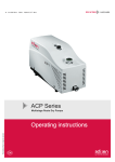
The pump operating principle
A hybrid technology
The ATH 400M and ATH 1000M integrate the advantages
of a multi-staged turbomolecular pump with a spiral helix
molecular drag section to enhance ultra high-vacuum (UHV)
and ultra clean technology (UCT).
The turbomolecular section provides high pumping speeds
and UHV ultimate vacuum.
The molecular drag section provides a high compression
ratio and extends forevacuum tolerance up to 5 mbar.
Inlet
Rotor
Stator
Dry back-up
bearings
Molecular drag
Edition 05 - October 96
Exhaust
Water cooling
Gas purge
Alcatel - High Vacuum Technology - User’s Manual ATH 400M / ATH 1000M
Motor
Magnetic
levitated bearings
1/4
A 20
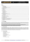
The pump operating principle
5 actives axis
The mobile assembly formed by the turbo rotor and
the shaft is known as the rotor. This rotor is driven by
the motor and held in suspension by magnetic fields
generated by electromagnets housed in active bearing,
type ACTIDYNE® maglev bearing (S2M Patent).
The mobile rotor has five axes of freedom monitored by
5 active bearings.
3 controlled translations (X, Y, Z)
Z
Y
X
Y
2 controlled rocking (X, Y)
Electronics
Bearing
Stator
Reference
signal
+
Signal
processing
Detector signal
2/4
+
Power
amplifiers
Rotor
Position
detector
+
Electromagnet
Alcatel - High Vacuum Technology - User’s Manual ATH 400M / ATH 1000M
Edition 05 - October 96
Movements in relation to these axes are monitored by
position sensors. According to the position data recorded,
the ACT controller corrects differences to bring the rotor
back to its optimum position, by varying the current in
electro-magnets.
A 20
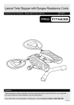
The pump operating principle
Automatic Balancing
System
The Automatic Balancing System is an electronic device.
That monitors the rotor position, allowing it to rotate on
its own axis of inertia.
Changes in the rotor balance, due to deposit built-up
during the life time of the pump, are automatically
compensated by the Automatic Balancing System.
Therefore, there is a total absence of vibration.
Rotor geometric axis
Stator geometric axis
Rotor inertia axis
The back-up bearings
Edition 05 - October 96
No maintenance
Battery free
They are dry-lubricated ceramic ball bearings.
They are never used in normal operation, since the rotor
is not in contact with the bearings.
The back-up bearings are only used to protect the pump in
accidental air in-rushes, accidental shocks or power failure.
By design, the pump doesn’t include parts liable to wear
and doesn’t need preventive maintenance. However, the
back-up bearings used in case of accidental shut-downs
have to be changed when the controller indicates it: the
percentage of landing time to be deducted depends on its
frequency of use (see D 10).
In case of a power failure, the motor acts like a generator,
supplying enough power for the magnetic bearings.
When the rotation speed is lower than the minimum setpoint,
the pump lands and shuts down on the back-up bearings:
the emergency breaking valve opens.
Alcatel - High Vacuum Technology - User’s Manual ATH 400M / ATH 1000M
3/4
A 20
The pump operating principle
The hybrid-turbo pump
in an installation
The valve is fitted in parallel
with purge port and opens
in case of events such as:
- uncontrolled violent shocks
applied to the pump;
- large accidental air
in-rushes.
It will also put the pump to
atmospheric pressure when
the controller is stopped.
This valve will slow down
the pump in complete safety.
At the pump exhaust, the gases are evacuated to
atmosphere by a primary pump.
Since the ATHM compression ratio is set by the design,
the ATHM limit the pressure is given by that of the primary
pump used.
INLET
PRESSURE
Chamber
to be
pumped
ATMOSPHERIC
PRESSURE
Primary
pumping
Secondary
pumping
Secondary vacuum
4/4
Primary vacuum
Alcatel - High Vacuum Technology - User’s Manual ATH 400M / ATH 1000M
Edition 05 - October 96
Emergency
braking valve
A 30
The different versions
Standard version
ATH 400M - ATH 1000M
An inverted dynamic seal
It creates a high compression ratio between the bearings
and the pump exhaust and thus minimizes the quantity of
corrosive gases in contact with the bearings.
When used with a gas purge for high flow rate
applications, the dynamic seal can, on its own, provide
excellent protection for corrosive applications.
Inlet
Inverted
dynamic
seal
Exhaust
Gas purge
ATH 400MT
ATH 1000MT
Edition 05 - October 96
The built-in heater band
In high pressure and high
throughtput processes such
as metal etch, deposit can
build up in the lower
compression stages of
the rotor, leading the pump
to early failure.
The built-in heater band
allows pump heating up to
75°C, which is sufficient to
prevent the condensation
effect.
This device is thermally
controlled by the ACT controllers.
Alcatel - High Vacuum Technology - User’s Manual ATH 400M / ATH 1000M
1/2
A 30
The different versions
Variation of the pump
rotational speed
The ATHM pump rotation speed can be selected and set
between a standby speed and the maximum speed.
This makes it possible to optimize pumping characteristics
according to each customer application (for example, high
pressure pumping).
A distinction is made between the following speeds:
- reduced speed (STANDBY speed) which can be set
between the low speed value and the maximum speed.
- maximum speed preselected at factory which corresponds
to the pump model.
depending on
operating conditions:
Min. speed
Max. speed
Inlet pressure ≥ 10-2 mbar
or
Housing temperature ≥ 50°C
ATH 1000MT
(with temperature
control)
15000 rpm
30000 rpm
Inlet pressure ≤ 10-2 mbar
or
Housing temperature < 50°C
ATH 1000M
15000 rpm
33000 rpm
Inlet pressure ≤ 10-1 mbar
ATH 400M
ATH 400MT
18000 rpm
39000 rpm
Edition 05 - October 96
Pump model
2/2
Alcatel - High Vacuum Technology - User’s Manual ATH 400M / ATH 1000M
A 40
ACT 600M and ACT 1000M controllers
The ACT 600M and the ACT 1000M controllers belong to
the new generation of ACT controller family.
Compact and functional
Dimension: 1/2 Rack.
Weigth: 8.5 kg (18 lb).
All functions to monitor the ATHM are integrated into
the controller.
Convenient interface
The front panel of the unit
consists of:
Parameter selection and
configuration keys
Manual control keys
{
ENTER
PREVIOUS
{
{
FAULT
START
STOP
STATUS
STAND BY
Edition 05 - October 96
ACT 600 M
Pump status indicator lights
Alcatel - High Vacuum Technology - User’s Manual ATH 400M / ATH 1000M
Parameter and message
LCD display (4 lines).
1/2
A 40
ACT 600M and ACT 1000M controllers
4
REMOTE CONTROL
RS 232
The rear panel of the unit
consists of:
5
0
1
1
PUMP CABLE
2
DRY CONTACTS
3
1 Power supply connector
3 Relay terminal strip
(Wiring characteristics
on B 80.)
- to replicate the monitoring parameters available in the
form of dry contacts.
4 Remote control
connector/RS 485
(Wiring characteristics
on B 90.)
- for the remote control of the START, STOP, STANDBY
functions;
- selectable 0 - 10 Volts output for speed, pump current or
temperature;
- heater band control temperature;
- external safety taken in account.
RS485 serial link allowing many pump installations in a
network.
5 RS 232 connector
(Wiring characteristics
on B 100.)
The RS 232 serial link is used to control and monitor the
pump using a computer.
2/2
Alcatel - High Vacuum Technology - User’s Manual ATH 400M / ATH 1000M
Edition 05 - October 96
2 Pump connector
A 50
The accessories
Pump accessories
Screen filter
Edition 06 - September 97
Compact filter
This filter protects the pump
against solid particles.
Mesh size 2.5 mm.
Inlet flange
100 ISO-KF
100 ISO-KF
100 CF-F
160 ISO-KF
160 ISO-KF
160 CF-F
200 ISO-KF
200 ISO-KF
200 CF-F
ASA 6"
(FPM)*
(NBR)*
(NBR)*
(FPM)*
(NBR)*
P.N.
056844
103070
056845
056942
103071
056928
063158
103072
063159
102933
This filter stops
particles ≥ 20 microns and
is used in the event of high
densities of dust or risks of
implosion when pumping
tubes or lamps.
Inlet flange
100 ISO-KF
160 ISO-KF
200 ISO-KF
P.N.
063215
063216
063911
Purge reduction device
This device is used to
reduce the purge gas flow
rate to 25 SCCM in some
processes.
Flow rate
25 SCCM
P.N.
066950
Isolation valve
at inlet pump
The secondary isolation
valve is used to maintain
the vacuum in the chamber
while the pump is reset to
atmospheric pressure.
See the Alcatel catalog.
An entire range of connection accessories are available in the Alcatel catalog
(clamping ring, centering ring, etc.).
Alcatel - High Vacuum Technology - User’s Manual ATH 400M / ATH 1000M
1/2
A 50
The accessories
Controller accessories
Connection cable
Length
1m
3.5 m
5m
10 m
15 m
P.N.
104624
103719
103720
103721
104587
Interconnecting cable
between heater band and
controller.
Length
1.0 m 115 V
1.0 m 230 V
3.5 m 115 V
3.5 m 230 V
5.0 m 115 V
5.0 m 230 V
10 m 115 V
10 m 230 V
15 m 115 V
15 m 230 V
P.N.
104627
105206
103728
103729
103730
103731
103732
103733
105202
105204
Edition 06 - September 97
Thermo. cable
Interconnecting cable
between pump and
controller.
2/2
Alcatel - High Vacuum Technology - User’s Manual ATH 400M / ATH 1000M
A 60
The technical characteristics
The performances
of the pumps
Model characteristics
ATH 400M
ATH 400MT
Inlet flange
DN
Rotation speed
rpm
Pumping speed*
100 ISO-K
160 ISO-K
ATH 1000M
160 ISO-K
39000
ATH 1000MT
200 ISO-K
160 ISO-K
33000
30000
N2
l/s
320
410
710
850
610
800
He
l/s
290
360
650
750
600
650
H2
l/s
180
230
430
450
330
350
N2
1x10+8
2x10+8
He
2x10+3
1x10+4
H2
1x10+2
4x10+2
8x10⁻⁹
8x10⁻⁹
mbar
1
1x10⁻¹
mbar
5
5
Noise level
dBA
≤ 39
≤ 39
Start-up time
min
<3
<5
Maximum start-up power
W
650
650
Maximum operating power
W
300
300
50
50
< 60
< 60
Compression rate*
200 ISO-K
Ultimate pressure without purge, meas.
according to Pneurop standard mbar
Maximum pressure at inlet
in continuous operation**
Maximum permissible
pressure at exhaust**
Edition 07 - January 02
N2 purge flow rate
SCCM
Cooling water flow rate
l/h
Water temperature
°C
Maximum ambient temperature
°C
40
40
Weight
kg
19
28
ADP 31
ADP 81
Recommended forepump
15 < T < 25°C
15 < T < 25°C
* See curves in G 10 and G 20.
** The two maximum pressure cannot occur at the same time.
Alcatel - High Vacuum Technology - User’s Manual ATH 400M / ATH 1000M
1/4
A 60
The technical characteristics
Dimensions
ATH 400M
or ATH 400MT
Exhaust
DN 40 ISO KF
5°
4
45°
1
7,
21
122
N2 Purge
DN 16 ISO KF
Water inlet and
outlet fittings
(1/4 NPT female
for copper pipe
5/16)
Inlet flange
Electrical
connection
45.6
83.5
N2 Purge
DN 16 ISO-KF
35.5
Ø193,5±0,2
2/4
Alcatel - High Vacuum Technology - User’s Manual ATH 400M / ATH 1000M
Edition 07 - January 02
H (mm)
292.5
272.8
298.9
294.5
279.8
31.5
Inlet flange
DN 100 ISO-K
DN 160 ISO-K
DN 100 CF-F
DN 160 CF-F
ASA 6"
128
H
Electrical connection
only for
thermostatic version
A 60
The technical characteristics
Exhaust
DN 40 ISO KF
Dimensions
Water inlet and outlet
ATH 1000M
or ATH 1000MT
45°
(any direction)
60°
60°
148.5
N2 Purge
DN 16 ISO KF
228.7
Inlet flange
Alcatel - High Vacuum Technology - User’s Manual ATH 400M / ATH 1000M
39.5
34.5
H (mm)
356.7
304.0
369.1
341.7
365.7
105.5
Inlet flange
DN 160 ISO-K
DN 200 ISO-K
DN 160 CF-F
DN 200 CF-F
ASA 6"
157.5
Edition 07 - January 02
H
Heating band thermal sensor
Electrical connection
Ø 242
3/4
A 60
The technical characteristics
Controller characteristics
Model characteristics
Weight
Dimensions HxWxD
ACT 600M
ACT 1000M
8.5
132.5 x 219 x 453
1/2 Rack 19"
kg
mm
Power supply
Nominal voltage
V
Frequency
Hz
Maximum power consumption VA
Customer main circuit breaker rating
Ambient operating temperature °C
85 to 132 - 170 to 264
48/63
750
10 A
T ≤ 50
219
54.75
122.4
132.5
Controller dimensions
109.5
PREVIOUS
+
ENTER
STATUS
STAND BY
FAULT
START
STOP
M4
453
414
150
4/4
Alcatel - High Vacuum Technology - User’s Manual ATH 400M / ATH 1000M
Edition 07 - January 02
112.5
5
ACT 1000 M
B 10
Safety instructions related to installation
Before switching on the pump, the user should
study the manual and follow the safety
instructions listed in the compliance certificate
booklet supplied with the pump.
Installation
Start-up
• The controllers must be connected to an electrical
installation including an ground connection in compliance
with decree 88.1056 of 14th November 1988.
• Our products are designed to comply with current EEC
regulations. Any modification of the product made
by the user is liable to lead to non-compliance with
the regulations, or even to put into doubt the EMC
(electromagnetic compatibility) performance and the safety
of the product. ALCATEL declines any responsibility for
such operations.
Edition 05 - October 96
• Before any maintenance operations on a product
performed by a maintenance technician who has not
received safety training (EMC, electrical safety, chemical
pollution, etc.), isolate the product from the various energy
sources (electricity, compressed air, etc.).
• The EMC performance of the product is obtained on
the condition that the installation complies with EMC rules.
In particular, in disturbed environments, it is essential to:
- use shielded cables and connections for interfaces,
- stabilize the power supply line with shielding from
the power supply source to a distance of 3 m from
the product inlet.
• The units containing control circuits are designed to
guarantee normal safety conditions taking their normal
operating environment into account (use in rack).
In specific cases of use on tables, make sure that no
objects enter the ventilation openings or block the openings
when handling the units.
Alcatel - High Vacuum Technology - User’s Manual ATH 400M / ATH 1000M
1/2
B 10
Safety instructions related to installation
Installation
Start-up
(continued)
• When switching off an item of equipment containing
loaded capacitors at over 60 VDC or 25 VAC, take
precautions concerning the access to the connector pins
(single-phase motors, equipment with line filter,
frequency converter, monitoring unit, etc.).
• When handling the equipment, use the devices provided
for this purpose (hoisting rings, handle, etc.).
• Risk of toppling over: although compliance with EEC
safety regulations is guaranteed (normal range ± 10°),
it is recommended to take precautions against the risk of
toppling over during handling, installation and operation.
• The performance and the operational safety of this
product are guaranteed provided that it is used in normal
operating conditions.
• The vacuum pump is also a compressor: incorrect use
may be dangerous.
Study the user manual before starting up the pump.
• Make sure that the parts or chambers connected to
the intake of our pumps withstand a negative pressure
of 1 bar in relation to the atmospheric pressure.
• The leaktightness of the products is guaranteed when
they leave the factory for normal operating conditions.
It is the user's responsibility to maintain the level of
leaktightness particularly when pumping dangerous gases.
2/2
Alcatel - High Vacuum Technology - User’s Manual ATH 400M / ATH 1000M
Edition 05 - October 96
• The access to the rotor of a turbomolecular pump with
an unconnected intake is dangerous. Similarly, if the pump
is not switched on, it may be driven by another pump in
operation (risk of injury).
B 20
Unpacking and storage
Unpacking
Unpack the equipment carefully and keep the packaging.
Make sure that the equipment has not been damaged
during the transport. If it has been damaged, take the
necessary steps with the carrier and inform Alcatel if
necessary.
In all cases, we recommend that you keep the packaging
(reprocessing material) to transport the equipment if
necessary or for prolonged storage.
To keep your product in the clean condition in which it left
our factory, we recommend to unpack the pump only on
its assemby site.
Weight of the complete shipping crate : 50 kg maxi.
Thermostatic
cable
Water valve
Edition 05 - October 96
Emergency
breaking valve
Electrical
cable
Controller
Inlet filter
screen
Turbomolecular
pump
Alcatel - High Vacuum Technology - User’s Manual ATH 400M / ATH 1000M
1/3
B 20
Unpacking and storage
The accessories
The controller
The pump
This packaging also contains other cardborad boxes, for
the accessories (screen filter, emergency braking valve,
water valve and purge device) and for the electric cable.
It is packaged in a separated cardboard box.
Lift the device out of its packaging (weight 8.5 kg) by hand.
It is packaged in a separated cardboard box.
Lift the ATH 1000M out of its packaging by using
the hoisting rings (weight 28 kg).
Inlet
Our equipment can be stored without special precautions
(ambient temperature between 5 and 40°C) .
ASA 6’’, ISO or CF-F
flange blanking and rotor
holding system.
Exhaust
Blanked with
a DN 40 ISO-KF protector.
Connection for
emergency braking valve
and nitrogen device
Blanked with
a DN 16 ISO-KF protector.
2/3
Alcatel - High Vacuum Technology - User’s Manual ATH 400M / ATH 1000M
Edition 05 - October 96
Pump storage
B 20
Unpacking and storage
Controller storage
The controller can be stored in its cardboard box at storage
temperature between - 20°C and + 70°C.
Storage mode
The controller is set in STORAGE mode at factory, to protect
internal RAM memory during transport and storage.
When the controller is powered, the storage mode
disappears automatically.
Edition 05 - October 96
Set the storage mode for prolonged storage when the pump
is stopped.
Alcatel - High Vacuum Technology - User’s Manual ATH 400M / ATH 1000M
3/3
B 30
Pump connections to an installation
Maglev pump connection
instructions
Why securing
MAGLEVpump installation ?
Maglev hybrid Turbopumps are designed so as to prevent
any safety hazard to the user in standard operating
conditions.
However, some operating conditions may generate hazards
for the user and the environment: the kinetic energy stored
in a maglev turbopump is very important. In case of a
mechanical failure an improperly installed pump could be
ejected from the equipment if the kinetic energy was
tansferred to the pump body.
It is absolutely necessary to install the pump according to
the following installation specifications to secure the user
and the equipment.
Alcatel declines any responsibility if the pump installation is
not design in accordance with these installation
specifications.
Edition 06 - January 02
Installation spécifications
Equipment
Frame
Alcatel - High Vacuum Technology - User’s Manual ATH 400M / ATH 1000M
1/7
B 30
Pump connections to an installation
Installation with bolted
flange
The kinetic energy of the rotor has to be absorbed by
the installation if the pump seizes suddenly.
The resulting maximum deceleration torque is based on
the assumption, that the rotor stops in half a turn and that
the whole energy has to be taken by the pump assembling
bolts.
Design and secure the pump frame so that it can withstand
the maximum deceleration torque.
Maximum deceleration
torque to stop the rotor in
half a turn (item 1)
• 9159 Nm for ATH 400 M at nominal speed 39000 rpm
• 20000 Nm for ATH 1000 M at nominal speed 33000 rpm
Inlet flange installation
conditions (item 2)
According to the housing type:
2/7
200
M 10
12
12-9
35+5
250
M 10
12
12-9
35+5
For safety reasons, it is important to tighten the bolts with a
torque wrench according to the specified values :
- lower torque: risk of loosened bolts
- higher torque: risk of damaging the bolts.
Alcatel - High Vacuum Technology - User’s Manual ATH 400M / ATH 1000M
Edition 06 - January 02
WARNING
Mounting holes at inlet flanges
Inlet flange
DN - ISO-F 160
Type of bolts dictated
M 10
Number of bolts dictated
8
Bolt metric grade
12-9
Installation torque per bolt N.m 35+5
B 30
Pump connections to an installation
Inlet flange installation
conditions (item 2))
(Continued)
Edition 06 - January 02
WARNING
Equipment installation
conditions (item 3)
We strongly recommend the use of ISO-F or CF-F flanges.
ISO-K type flanges are not recommended to fasten
turbomolecular pumps with inlet flange equal or larger
than DN 200 because:
• there is no visual reminder (like threaded holes on ISO-F)
to signal how many clamps are needed to secure the
pump,
• it is not as easy to fasten claw clamps on ISO-K flanges
as to secure bolts on ISO-F flanges,
• the ISO-K flanges do not prevent accidental rotation of
the pump on the equipment flange in case of pump rotor
crash. This rotation could damage the foreline and the
purge gas line which would generate hazards for the
user.
The equipment frame on which the pump is installed must
be sufficiently rigid to absorb the kinetic energy of the rotor
in case of pump rotor crash. For this, take into account:
• the maximum deceleration torque to calculate the
equipment attachment devices,
• the flange dimensions,
• the quality and the number of screws,
no reducing adaptater or bellows should be installed
between pump inlet flange and the chamber.
Alcatel - High Vacuum Technology - User’s Manual ATH 400M / ATH 1000M
3/7
B 30
Pump connections to an installation
The pump can operate
in any position
In.
In.
In.
In.
Rotor flanging device
disassembly
To prevent the pump maglev bearings
from being damaged due to shocks
during transport, the rotor is flanged to
the pump housing.
Welcome
The pump must never be swiched in
this condition. This flanging must only be
removed when the pump is to be installed.
Edition 06 - January 02
We recommend that you keep the flanging to transport
the equipment.
4/7
Alcatel - High Vacuum Technology - User’s Manual ATH 400M / ATH 1000M
B 30
Pump connections to an installation
Vacuum connections
Remove the protective parts blocking the inlet,
exhaust and purge openings: these components
prevent foreign bodies from entering the pump
during transport and storage. It is dangerous to leave them
on a pump in operation.
At inlet:
Edition 06 - January 02
Secondary isolation valve
Install the screen filter or compact filter accessory on
the pump; connect the pump to the installation or connect
a secondary isolation valve.
It is recommended to
install an isolation valve
between
the chamber to be
pumped and the pump
inlet to maintain
the pressure in
the chamber while
the pump is reset to
atmospheric pressure.
This valve can be driven
by the controller
(«ISOL.VALVE» contact
see B 90).
Secondary
isolation valve V2
2
1
ACT - Dry Contacts
Screen filter
ATH
If the controller stops the pump by opening the emergency
braking valve, the contact opens and closes the secondary
isolation valve.
Alcatel - High Vacuum Technology - User’s Manual ATH 400M / ATH 1000M
5/7
B 30
Pump connections to an installation
At exhaust:
Primary isolation valve
It is highly recommended to install an isolation valve,
(closed with power off) between the ATH pump and
the roughing circuit.
The valve is closed using the « START » contact on the
controller. If the valve is missing, the time taken to slow
down in the event of an accident is increased, thereby
reducing the service life of the back-up bearings.
Connect this valve such as an Alcatel bracket valve as
near the pump exhaust as possible depending on the
space available and the accessories installed.
Connect the valve to the primary pumping circuit*.
12
Primary
pump
K1
Customer
relay
V1
K1
ATH
Primary
isolation
valve
K1
Edition 06 - January 02
Dry Contacts
11
* Different connection accessoiries can be found in the Alcatel Catalog.
6/7
Alcatel - High Vacuum Technology - User’s Manual ATH 400M / ATH 1000M
B 30
Pump connections to an installation
Typical connection
- A primary isolation valve V1 between the ATH and
the roughing pump;
- a secondary isolation valve V2 between the ATH and
the chamber to be pumped;
- a relay K1, their contacts drive the valve V1 and the
primary pump power supply;
- the thermostatic option.
Stand-by
Remote
Control
Remote
In this installation, we use:
Start
External
Safety
Temp.
sensor
supply
12
4
11
3
10
2
9
1
7
6
5
12
Start
11
Customer wiring
ACT
Secondary
isolation valve V2
Customer
relay
Heating
band
ATH
Water valve
K1
N2
Emergency
breaking
valve V3
6
Dry Contacts
Primary
isolation
valve V1
Thermostat
5
4
K1
Air Inlet
3
2
Isolation Valve
1
Pump cable
Edition 06 - January 02
Power
supply
Alcatel - High Vacuum Technology - User’s Manual ATH 400M / ATH 1000M
7/7
Legend
Minimum electrical connection
Thermostatic cable for ATH MT
Customer supplies recommended by Alcatel
Primary
pump
K1
B 40
Emergency braking valve connection
The braking valve must be connected to ensure
the pump’s safety and durability.
Function
In the event of a major problem (magnetic bearings fail,
external shock...), the pump must be stopped as soon as
possible to prevent damage to the back-up bearings.
The emergency braking valve is calibrated to reset
the volume of the pump to atmospheric pressure.
When the pump is isolated (at inlet and exhaust) the rotor
slow down efficiency is increased.
The reset to atmospheric pressure takes place when faults
are registered on the controller which stops the pump and
controls the air inlet (see D 20).
Vacuum connection
Air inlet
or Dry
Nitrogen
Edition 05 - October 96
Blank-off frange
Install the calibrated emergency braking valve on
the DN 16 fitting of the pump.
The valve must be connected to an air inlet line which
can be for example dry nitrogen (Pressure between 1 and
1.5 bars absolute) (see B 50 for nitrogen characteristics).
Alcatel - High Vacuum Technology - User’s Manual ATH 400M / ATH 1000M
1/2
B 40
Emergency braking valve connection
ATH
Connect the valve powered
and driven by the controller
via the «AIR INLET» contact
on the Dry Contacts
connector (see B 90).
Dry Contacts
Electrical connection
4
Emergency
breaking valve
Edition 05 - October 96
3
V3
2/2
Alcatel - High Vacuum Technology - User’s Manual ATH 400M / ATH 1000M
B 50
Nitrogen purge device connection
Characteristics of
of filtered
dry nitrogen supply
Purge connection
A filtered dry nitrogen supply with the following
characteristics is required:
- Dew point < 22°C
- Dust < 1 µm
- Oil < 0.1 ppm
- Absolute pressure of 1 to 1.5 bar.
The nitrogen purge must be connected to the
braking valve so as not to disturb its operation
and not between the valve and the pump.
Connect the nitrogen supply to the DN 16 purge fitting*.
The nitrogen flow reduction device controls the pressure
and guarantees a flow rate of 50 SCCM at pressure
1.1 bars.
Edition 05 - October 96
1st case:
Purge can be stopped
during pump running
Emergency braking valve
N2 purge
Reduction device
Notched fitting
* Différent connection accessories can be found in the ALCATEL catalog.
Alcatel - High Vacuum Technology - User’s Manual ATH 400M / ATH 1000M
1/2
B 50
Nitrogen purge device connection
2nd case:
Continous operation
of the purge
Emergency braking valve
Reduction flow purge device
N2 purge
Long nipple
Connect the little flexible pipe between the long nipple and
the valve.
Feed the nitrogen purge
throughout pumping
according to the flow rate
and pressure values in
the scale given.
Flow rate (SCCM)
70
60
Pur
2/2
SC
50
Pur
40
For limited the flow rate
at 25 SCCM, connect
the nitrogen flow reduction
device accessory
(see A 50).
g
0
e5
g
5
e2
CM
SC
CM
30
20
1.0
Absolute pressure at inlet (bar)
1.1
1.2
1.3
1.4
1.5
Alcatel - High Vacuum Technology - User’s Manual ATH 400M / ATH 1000M
Edition 05 - October 96
Adjust the flow rate
B 60
Water cooling connection
Characteristics
of water cooling
For ATH 1000M models
Edition 07 - January 02
For ATH 400M models
In order to limit the corrosion and clogging of the cooling
pipes, it is recommended to use cooling water with the
following characteristics:
- treated soft water or non-corrosive industrial water
- pH between 7.5 and 11
- hardness < 7 milli-equivalent/dm3
- Resistivity > 1500 Ω.cm
- Solid pollution < 100 mg/dm3
- Max. pressure: 7 bars
- Temperature: 15 < T < 25°C
- Flow rate: 60 l/h
- Provide a water inlet pipe
and a tap to adjust the flow rate.
- Install the two male connector
delivered on the cooling
device (connector 1/8 NPT)
- Connect the water inlet
line to one of the cooler nipples,
with the other nipple connected
to the water draining circuit via
a flexible tube (ext. diam 1/4’)
(supplied by customer).
- Connect the water inlet
line to one of the cooler
water fittings 1/4 NPT female
on the pump, with the other
fitting connected to the water
draining circuit via a tube
(supplied by customer).
Alcatel - High Vacuum Technology - User’s Manual ATH 400M / ATH 1000M
1/2
B 60
Water cooling connection
For ATH 400MT
or ATH 1000MT models
b
- Provide a water inlet pipe
and a tap to adjust the flow
rate.
- Assemble the valve holding
stirrup on the pump frame
(3 positions a,b,c).
- Install the water electrovalve
on its holding.
- Install the water valve to
the water inlet line using
a flexible tube following
the position on the assembly
diagram:
- Connect the other nipple
to the draining circuit.
a
c
water
outlet
2
water inlet
Electrical connection
7
6
5
Dry Contacts
Heating
band
ATH
Water
valve
6
5
Connect the water valve via the «THERMOSTAT» contact
on the DRY CONTACTS connector and supply it via
the thermostatic cable.
2/2
Alcatel - High Vacuum Technology - User’s Manual ATH 400M / ATH 1000M
Edition 07 - January 02
Remote
B 70
Heating band connection
For ATH 400MT
and ATH 1000MT
Connection
These pumps are equipped with an heating band,
a thermal sensor and a valve to regulate the water flowrate.
The body of the pump can be heated to 75°C to avoid gas
condensation in the pump on the semiconductor processes.
Connect the thermostatic cable as follows:
Don’t forget to connect the
connector to the ground (under
the pump cable socket).
Connect to the heating
band on the pump
Thermostatic cable
Connect to
the « Remote Control »
connector on
terminals 5-6-7
Connect to
the water valve
REMOTE CONTROL
RS 232
Edition 05 - October 96
0
1
PUMP CABLE
DRY CONTACTS
Connect to
the « Dry Contacts »
on terminals 5-6
Connect the thermostatic cable
to the power line
(main with ground connection).
Alcatel - High Vacuum Technology - User’s Manual ATH 400M / ATH 1000M
1/2
B 70
Heating band connection
Heating band temperature
Remote
7
6
5
ATH
Heating
band
Dry Contacts
Water
valve
6
5
The temperature can be choosen on the controller
(between 31 and 75°C or NO°C).
By choosing «NO°C» temperature, the heating band is
switched off and the pump is cooled permanently.
If there is a failure on the temperature sensor on
the heating band, the controller display indicates:
PUMP-TEMP2
00°C
DEF 38
TEMP.SENSOR 2
Hot surfaces are signalled by
symbol.
The pump housing temperature can reach 75°C.
2/2
Alcatel - High Vacuum Technology - User’s Manual ATH 400M / ATH 1000M
Edition 05 - October 96
The heating band is switched off and the pump is cooled
permanently.
The temperature of the heating band can be read on
the display of the controller (see C 30).
B 80
Electrical connection
Controller installation
The unit must be installed in an environment ventilated
either by natural convection or by the movement of forced
air. Cooling is normally performed by an internal fan which
ventilates air from the inside to the outside of the unit.
Make sure that:
- the openings on the bottom, top and rear of the unit are
not blocked;
- the ambient temperature does not exceed 50°C;
- a free space of at least 15 mm is left behind and below
the unit.
Connections
Connect the controller to the pump using
the cable ordered.
Connect the connector with
square and screw M3
to respect the EMC.
REMOTE CONTROL
RS 232
0
PUMP CABLE
1
Edition 05 - October 96
DRY CONTACTS
Delayed fuses (x2) located
below the controller:
16A - T - 250V
P.N. 103313
If the unit is remote
controlled, make the
various connections
on the REMOTE CONTROL
(see B 100).
Connect the RS232
serial link cable to the
connector (cable supplied
by customer).
(see B 110 and B 120).
Some output contacts are
available on terminal
DRY CONTACTS (see B 90).
Connect the controller
to the power supply using
the cable supplied.
(Main with ground connection).
Alcatel - High Vacuum Technology - User’s Manual ATH 400M / ATH 1000M
1/1
B 90
«Dry contacts» relay wiring
Signaling using output
contacts:
These are dry contacts
(220VAC - 3A):
their functions are to copy
the data concerning the
pump operating status.
Isol. valve 1 - 2
1
2
3
4
5
6
7
8
9
10
11
12
When the controller detects a bearing operating
fault or after a stop, it opens the contact.
This contact must be used to control a secondary
isolation valve which is used to maintain the
pressure in the chamber while the pump is reset
to atmospheric pressure.
Air inlet
3 - 4 When the controller detects a bearing operating
Speed
7 - 8 the selected speed.
fault, it stops the power supply to the emergency
braking valve (12V-5W): the valve opens and air
enters.
The contacts is closed when the pump reaches
9 - 10 The contact is opened if a faults appears.
Fault
Thermostat 5 - 6 The contact is opened or closed, depending on
the pump temperature and the selected temperature.
Edition 05 - October 96
Start
Contact
functionnal status
11 - 12
Power off
ISV
Thermos.
Speed
Fault
Start
The contact is closed when the «START» control is
activated on the controller.
The contact can be used to control a primary
isolation valve, and via a power relaying device,
to control a primary pump.
Power on
Stop
Start on
Nominal speed
Alarm
Defect
1
0
1
Depending on temperature parameter
0
1
0
Depending on speed
1
0
1
0
Alcatel - High Vacuum Technology - User’s Manual ATH 400M / ATH 1000M
1/1
B 100
"Remote Control" connector wiring
When the units containing the control circuits are equipped with dry contact
outputs, it is the customer’s responsibility to use the outputs in compliance with
safety regulations.
Analog output (0-10V)
0V
Temp. sensor input
Temp. sensor
main supply +15V
GND (ground)
The control contact
1
2
9
4
3
10
11
5
12
6
13
7
14
8
15
RS485 V(+)
RS485 V(-)
Ext. safety
1-9
Start/Stop
Edition 06 - September 97
(in remote mode)
2 - 10
When the contact is closed, an external safety
device is signalled: the motor is stopped and the
controller generates a fault. This contact must be
opened for the pump to operate. The emergency
valve is opened.
When the contact is closed, the pump is started
up and accelerates to reach its nominal speed or
reduced speed (depending on parameter settings).
If the contact is open, the pump is no longer
powered.
REMOTE
Mode
3 - 11
When the contact is closed, the remote control
mode is selected. The actions on the keyboard
are without effect.
If the contact is open, the local mode is selected
(control using the front panel keypad).
STANDBY Mode
4 - 12
When the contact is closed, the reduced speed
rotation mode is selected.
Temp. Sensor
5-6-7
These contacts allows to read the heating band
temperature.
Analog.
Output
8 - 15
Used to monitor the selected parameter
(see ANALOG OUT menus C 30).
Alcatel - High Vacuum Technology - User’s Manual ATH 400M / ATH 1000M
1/2
B 100
"Remote Control" connector wiring
Analog output signal
The signal is transmitted between terminal 8 and 15 of
the remote connector.
Five values can be used to plot curves:
θ1 Pump temperature:
(θ1 PUMP)
0°C
(OV) to
100°C
(10V)
θ2 Pump temperature:
(θ2 PUMP)
0°C
(OV) to
100°C
(10V)
Pump rotation speed:
(SPEED)
360 rpm (OV) to 30000 rpm (5V)
360 rpm (OV) to 33000 rpm (5.5V)
360 rpm (OV) to 39000 rpm (6.5V)
15000
60000
100
100
100
Pump temperature 1 (°C)
Pump temperature 2 (°C)
(OV) to
Converter temperature (°C)
0 mA
Speed (rpm)
(OV) to
Motor current (mA)
Motor current:
(I MOTOR)
0°C
0
0
0
0
0
100°C
(10V)
8700 mA (5.8V)
Voltage (V)
0
10
Factory configuration is setted on (SPEED).
2/2
Alcatel - High Vacuum Technology - User’s Manual ATH 400M / ATH 1000M
Edition 06 - September 97
Controller temperature:
(θ CONV)
B 110
RS 232 or RS 485 serial link wiring
At the first power-up, the user finds the default
configuration. The serial link parameters can be modified
by accessing the corresponding unit menu (see C 30).
The default configuration of the serial link is as follows:
■
■
■
■
■
Type: RS 232
Transmission speed: 9600 bauds
Data length: 8 bits
Parity: NONE
Stop bit: 1
Refer to C 30 to customize the parameters.
RS232 connector wiring:
(Reception data) RD
TD (Transmission data)
(Data set ready) DSR
DTR (Data terminal ready)
GND (Ground)
1
2
6
3
7
4
8
5
9
DB 9 contacts, male connector.
Connection examples:
1
1
6
6
RS232 type serial link
with a single controller
ENTER
PREVIOUS
FAULT
5
9
START
STOP
STATUS
STAND BY
ACT 600 M
Edition 05 - October 96
9
5
The multiple link is obtained by creating a loop:
Multiple RS232 serial link:
several units (up to 999) can
be controlled on a single link.
1
6
5
9
1
6
Alcatel - High Vacuum Technology - User’s Manual ATH 400M / ATH 1000M
5
9
1
6
5
9
1
6
5
9
1/2
B 110
RS 232 or RS 485 serial link wiring
RS485 connector wiring:
1
2
9
4
3
10
11
5
12
6
13
7
14
8
15
RS485 V(+)
RS485 V(-)
«Remote Control» connector 13 and 14 pins
DB 15 contacts, male connector.
(13)
(14) +
(13)
(14) +
(13)
(14) +
Edition 05 - October 96
Multiple RS485 serial link:
several units (up to 999) can
be controlled on a single link.
2/2
Alcatel - High Vacuum Technology - User’s Manual ATH 400M / ATH 1000M
B 120
Detailed description
of RS232 and RS485 commands
(valid from V.2.03 version controller)
Conventions applicable
to the syntax of all
commands:
Status values
Error messages
ADR
Syntax
Result
adr = address, from 000 to 255
<CR> Carriage Return (ascii 13)
<LF> Line Feed (ascii 10); between square brackets:
this character is not compulsory.
OK
: command executed correctly
Err0
Err1
Err2
Err3
Err4
:
:
:
:
:
adjustment error (out of bounds)
command error (syntax)
parameter error (e.g. non-hexadecimal character)
context error
checksum error
Specifies the address of the device for networking.
#adrADR,aaa<CR>[<LF>]
adr
= address of the device before the command
aaa
= new address of the device
condition : 000 ≤ aaa ≤ 255
#aaa,OK or Err2
Edition 06 - September 97
This command is used to allocate a specific number to
each of the products making up a network
(loop for RS 232 or parallel for RS 485).
Note : it is important to note down the number
allocated to each device.
DEF
Syntax
Result
List the faults
#adrDEF<CR>
List the faults separated by the separator character.
#adr,OK if there is no fault
Alcatel - High Vacuum Technology - User’s Manual ATH 400M / ATH 1000M
1/9
B 120
Detailed description
of RS232 and RS485 commands
DLI
Syntax
Result
See also: DLR
DLR
Syntax
Result
Defines the DataLogger transmission interval
#adrDLI,xxx<CR>[<LF>]
xxx: DataLogger send interval in seconds
condition: 001 ≤ xxx ≤ 255
#adr,OK or Err2
Note: if OK, the interval sent is stored in user memory.
Enables DataLogger operation (only with RS232)
#adrDLR<CR>[<LF>]
#adr,OK
The main characteristics of the pump and its controller
are sent over the RS link, at the rate defined by the DLI
command.
Note: any new characters arriving on the serial port
(RS 232) will cancel the automatic DataLogger transmission.
Syntax
2/9
List the data (data only)
#adrGETAI<CR>[<LF>] : List analog inputs
#adrGETLI<CR>[<LF>] : List logical inputs
#adrGETLO<CR>[<LF>] : List logical outputs
Alcatel - High Vacuum Technology - User’s Manual ATH 400M / ATH 1000M
Edition 06 - September 97
GET
B 120
Detailed description
of RS232 and RS485 commands
IDN
Syntax
Result
Identifies the device which is communicating, and its
software version
#adrIDN<CR>[<LF>]
#adr, ACT1000M Vx.zz
Returns the type of Variable drive Supervisor, the software
version (x), the software edition (zz).
LEV10
Returns the state of the parameters defined by SET
Syntax
#adrLEV10<CR>[<LF>]
Edition 06 - September 97
Result
#adr,nnnnn,sssss,00000,0,ccccc,eeeee,ddddd,pppp,qqqq,
jj,kk,000,mmm
Returns current values:
nnnnn : nominal speed set point (in rpm)
sssss : stand-by speed set point (in rpm)
00000: not used
0
: not used
ccccc : pump working time (in hours)
eeeee : electronic working time (in hours)
ddddd : start delay (max 14459 s,
that is 240 mn 59 s)
pppp : time to venting (max 3599 s,
that is 59 mn 59 s)
qqqq : venting time (max 3599 s,
that is 59 mn 59 s)
jj
: speed threshold for relay (3 to 50 %)
kk
: control temperature (30 to 75°C)
00
: not used
mmm : bearing current value (0 to 100 %)
Alcatel - High Vacuum Technology - User’s Manual ATH 400M / ATH 1000M
3/9
B 120
Detailed description
of RS232 and RS485 commands
NOW
Display date and time
Syntax
#adrNOW<CR>[<LF>]
Result
NSP
Syntax
Result
MM/DD/YY
HH:MM:SS
Switches the speed set point to the nominal speed value
#adrNSP<CR>[<LF>]
#adr,OK
The speed set point for the pump is set to its nominal
value.
Syntax
Result
Used to select possible user choices
#adrOPT01,n<CR>[<LF>]
choice of parameters on the analog output:
n = 0 : real pump speed
n = 1 : pump current
n = 2 : temperature of pump body
n = 3 : temperature of internal electronics
#adr,OK
Comment: The choice of the temperature unit affects
the results of the DLR and STA strings and the display
(if cabinet fitted).
4/9
Alcatel - High Vacuum Technology - User’s Manual ATH 400M / ATH 1000M
Edition 06 - September 97
OPT
B 120
Detailed description
of RS232 and RS485 commands
RPM
Syntax
Result
Defines the speed set point in stand-by mode
#adrRPM,nnnnn<CR>[<LF>]
#adr,OK or #adr,ErrX
1, out of range; 2, parameters ; 3, context
(not in Stand-by mode)
Comment: if OK, the new speed is automatically stored in
user memory.
SBY
Syntax
Result
Switches the speed set point to the stand-by value
#adrSBY<CR>[<LF>]
#adr,OK
Edition 06 - September 97
Resets the stand-by speed to its last stand-by stored value,
and allows it to be modified if an «RPM» command is sent.
This configuration is automatically stored in user memory.
SEL10
Returns the state of the parameters defined by OPT
Syntax
#adrSEL10<CR>[<LF>]
Result
#adr,a,0,0,0
a : Returns choice of parameters on the analog output:
a = 0 : real pump speed
a = 1 : pump current
a = 2 : temperature of pump body
a = 3 : temperature of internal electronics
0,0,0 : not used
Alcatel - High Vacuum Technology - User’s Manual ATH 400M / ATH 1000M
5/9
B 120
Detailed description
of RS232 and RS485 commands
Syntax
SET
Syntax
Result
6/9
List all the data (titles and data)
#adrSCR<CR>[<LF>] : List all the data
#adrSCRAI<CR>[<LF>] : List all the analog inputs
#adrSCRAO<CR>[<LF>] : List all the analog outputs
#adrSCRLI<CR>[<LF>] : List all the logical inputs
#adrSCRLO<CR>[<LF>] : List all the logical outputs
Defines the internal operating parameters
#adrSET10,ccccc<CR>[<LF>] : pumping working time
(in hours)
#adrSET11,eeeee<CR>[<LF>] : electronic working time
(in hours)
#adrSET13,ddddd<CR>[<LF>] : start delay (max 14459s,
that is 240mn 59s)
#adrSET14,pppp<CR>[<LF>] : time to venting (max 3599s,
that is 59mn 59s)
#adrSET15,qqqq<CR>[<LF>] : venting time (max 3599s,
that is 59mn 59s)
#adrSET30,jj<CR>[<LF>] :
speed threshold for relay
(3 to 50 %)
#adrSET31,kk<CR>[<LF>] :
control temperature
(30 to 75°C)
#adrSET33,mmm<CR>[<LF>] : bearing current value
(0 to 100 %)
#adr,OK or ErrX
Alcatel - High Vacuum Technology - User’s Manual ATH 400M / ATH 1000M
Edition 06 - September 97
SCR
B 120
Detailed description
of RS232 and RS485 commands
SEP
Syntax
Result
Defines the character which separates the parameters
in a reply
#adrSEP,nnn<CR>[<LF>]
nnn: 3-digit decimal value of the ascii code of
the desired character (with leading zeros).
condition : 000 ≤ nnn ≤ 255
#adr,OK or #adr,ErrX if error
Allows the user to select the character which separates
the parameters returned by the DLR, STA and LEV
commands.
Default value: comma «,» ascii code = 044
If ok, the selected value is automatically stored in user
memory.
SPD
Syntax
#adrSPD<CR>[<LF>]
#adr,nnnnn
Edition 06 - September 97
Result
Returns the current speed
Alcatel - High Vacuum Technology - User’s Manual ATH 400M / ATH 1000M
7/9
B 120
Detailed description
of RS232 and RS485 commands
Syntax
Result
Returns the status of the internal dynamic parameters
#adrSTA<CR> or STA<CR>
#adr,s,rrrrr,vvv,www,xxx,yyy,zzz,aaa,bbbbb,cccc,ddd,eee,
fff,gggggggggggggggggggg<CR>
adr:
address
s:
order status
Bit
7
6
0
1
1
OFF
-
rrrrr:
vvv:
www:
xxx:
yyy:
zzz:
8/9
speed in rpm
Radial v13
Radial w13
Radial v24
Radial w24
Axial z12
5
4
LOCAL STOP
OFF
ON
OK
fault
3
RS
2
REM
OFF
ON
OFF
ON
aaa:
bbbbb:
cccc:
ddd:
eee:
fff:
1
0
STDBY START
OFF
ON
OFF
ON
Motor voltage V
Motor current mA
Motor load W
Pump temp 1 (°C)
Pump temp 2 (°C)
Controller temp (°C)
g
0 = OK
1 = ALERT
0
1
2
3
0=OK
0=OK
0=OK
0=OK
D02: motor overheat
D03: converter overheat
4
5
6
7
8
9
10
11
12
13
14
15
16
17
18
19
20
0=OK
0=OK
0=not used
0=not used
0=not used
0=OK
0=OK
0=OK
0=OK
0=OK
0=OK
0=OK
0=OK
0=OK
0=OK
0=OK
0=not used
2 = FAULT
D04: hall sensor
D05: permanent fault
sensor
D06: external safety
D31: jump DT0/DT1/DT2
D23: hot pump
D22: controller temp.
D14:
D15:
D16:
D17:
D18:
D21:
v13
w13
v24
w24
z12
overheat-1
D26: wires disconnected
D27: converter memory
D28: pump memory fault
D29: input power failure
Alcatel - High Vacuum Technology - User’s Manual ATH 400M / ATH 1000M
Edition 06 - September 97
STA
B 120
Detailed description
of RS232 and RS485 commands
TIT
Syntax
TMP
Syntax
#adrTITAI<CR>[<LF>] : List analog inputs
#adrTITLI<CR>[<LF>] : List logical inputs
#adrTITLO<CR>[<LF>] : List logical outputs
Defines the operating state of the turbomolecular pump
#adrTMPON<CR>[<LF>]
#adrTMPOFF<CR>[<LF>]
start pump rotation
stop pump
#adr,OK or #adr,Err3 if the pump is already in the state
requested (context error)
Edition 06 - September 97
Result
List the data titles
Alcatel - High Vacuum Technology - User’s Manual ATH 400M / ATH 1000M
9/9
C 10
Safety instructions related to operation
Before using the controller, make sure that the mechanical and electrical
connections have been made (see chapter B).
If an error message is displayed during operation, see D 20.
The machines are designed so as not to present a thermal risk for the user’s safety.
However, specific operating conditions can generate temperatures which require
particular care to be taken by the user (external surfaces > 70°C).
Avoid moving or causing a shock on a pump in operation.
There is a risk of seizing if the pump rotates in an axis perpendicular to its axis of
rotation.
The emergency braking valve must be connected (see B 40) to ensure the pump’s
safety and durability.
As long as the pump is running, the emergency braking valve has to be supplied
with neutral gas.
Edition 06 - September 97
The controller should never be switched off as long as the rotor is moving.
It is highly recommended to install:
• a screen filter at the pump inlet;
• an isolation valve between the chamber to be pumped and the ATH pump;
• an isolation valve between the ATH pump and the backing pump.
Alcatel - High Vacuum Technology - User’s Manual ATH 400M / ATH 1000M
1/1
C 20
Controller start-up
Once the various electrical connections have been made, set
the main switch on the rear panel to "I".
The controller performs
a self-test and
identifies the pumps to which
it is connected.
The initialization time is
approximately 4 seconds.
Display initialization:
■■■■■■■■■■■■■■■■■■■ ■ ■
■■■■■■■■■■■■■■■■■■■ ■ ■
■■■■■■■■■■■■■■■■■■■ ■ ■
■■■■■■■■■■■■■■■■■■■ ■ ■
The equipment is identified,
the program version is
displayed.
ACT 1000M
V2.03
---------------------------------------------CHECKING PROCEDURE
Indicator light test:
they are lit in succession.
FAULT
12/05/96
SPEED
θ1. PUMP
The working screen is
displayed.
12:24:54
: 0 RPM
21°C
The parameter setting keys
Parameter setting
access
PREVIOUS
• used to move in the menus, or from one parameter to another.
• used to select or adjust the value of the selected parameter.
Selection
Edition 06 - September 97
Validation
• used to access the parameter setting mode.
• used to exit the various menus without validating the functions.
ENTER
• used to validate the selection of a menu, parameter or value.
STATUS
• used to exit the menus and return to the pump parameter
display.
Configure the parameters
for the application using
the various menus.
Enter the sub-menus by pressing
PREVIOUS
DISPLAY
PARAMETERS
➧
➧
Display and/or select
the parameters to be
monitored (see C 30).
Access the parameter
programming
(see C 30).
Alcatel - High Vacuum Technology - User’s Manual ATH 400M / ATH 1000M
1/1
C 30
Configuring the controller
for the application
PARAMETERS
Factory
configuration
Programming
the parameters
ENTER
Modify the date
DATE
Modify the STANDBY speed
SPEED
(see A 30)
15000
ATH 1000M
18000
ATH 400M
Edition 06 - September 97
Modify the time before starting
up the pump
START
DELAY
Modify the heating
temperature
TEMP
Modify the RS232 serial link
or RS485
RS 232
ENTER
Configure the 0-10V output
AN.OUT
ENTER
For Alcatel Customer Support
RESET
ENTER
Modify the time before
opening the air inlet valve
AIR
ENTER
ENTER
Modify the air inlet valve
opening time
0 to 59mn 59s
31 to 75°C or
NO°C (for ATH MT)
RS 485
SPEED
I.MOT
θ1 . P U M P
θ. C O N V
θ2 . P U M P
0mn 0s
65°C
(see details page 2/4)
SPEED
1 V per 6000 rpm
I.MOT
1V per 1.5 A
θ.PUMP
0.1V per 1°C
θ.CONT 0.1V per 1°C
θ.PUMP
0.1V per 1°C
SPEED
CONVERTER
BEARING
DELAY
0 to 59mn 59s
1s
VENTING TIME
0 to 59mn 59S
1s
-3%
For Alcatel Customer Support
RELAY
Change to storage mode
(see B20).
STOCK
Parameter menu
PREVIOUS
Alcatel - High Vacuum Technology - User’s Manual ATH 400M / ATH 1000M
1/4
C 30
Configuring the controller
for the application
TYPE :
RS 232
RS 485
Factory
configuration
(see folio 2/4)
ENTER
Transmission speed
SPEED
300 600 1200 2400 4800 9600
9600
Data length
DATA
7 or 8
8 bits
Parity
PARITY
None Even Odd
None
Number of STOP bits
STOP
1 or 2
1 bit
Number of controller in
a multiple link
ADDRESS
0 to 999
Authorizes or does not
authorize the echo of
characters received on the link
ECHO
ON or OFF
Data separating character
SEPARATOR
1 to 127
Authorizes transmission at preset
intervals on the serial link
DATA LOGGER
Set the transmission interval
PREVIOUS
OFF
44
(comma)
START
ON or OFF
OFF
DELAY
0 to 240mn
1s
Twice
Edition 06 - September 97
(see folio 1/4)
ENTER
0
2/4
Alcatel - High Vacuum Technology - User’s Manual ATH 400M / ATH 1000M
C 30
Configuring the controller
for the application
(see folio 3/4)
Factory
configuration
TYPE :
RS 232
RS 485
ENTER
Transmission speed
SPEED
300 600 1200 2400 4800 9600
9600
Data length
DATA
7 or 8
8 bits
Parity
PARITY
None Even Odd
None
Number of STOP bits
STOP
1 or 2
1 bit
Number of controller in
a multiple link
ADDRESS
0 to 999
Authorizes or does not
authorize the echo of
characters received on the link
ECHO
ON or OFF
Data separating character
SEPARATOR
Authorizes transmission at preset
intervals on the serial link
DATA LOGGER
Edition 06 - September 97
Set the transmission interval
(see folio 1/4)
PREVIOUS
1 to 127
ENTER
0
ON
44
(comma)
START
ON or OFF
OFF
DELAY
0 to 240mn
1s
Twice
Alcatel - High Vacuum Technology - User’s Manual ATH 400M / ATH 1000M
3/4
C 30
Configuring the controller
for the application
The various indicators
on the display:
12/05/96
12:24:54
SPEED
: 33000 RPM
θ1 . P U M P
75°C
HOT PUMP - HOT PUM
1st parameter
2nd parameter
3rd parameter
Messages
3 parameters can be selected in the pull-down menu
from the list below:
- the current date and time;
- the rotation speed of the pump in «rpm»;
- the current pump motor (mA);
- the pump internal temperature and the housing
temperature of the pump (°C);
- the temperature of the controller (°C);
- the number of hours that the pump is in operation (h);
- the number of hours that the controller is in operation (h);
- the % life remaining on the back-up bearings (%) before
changing the bearings.
When switched on, the controller displays: the date and
time, the rotation speed and the pump temperature.
Configuring
the display screen
ENTER
The date and time
DATE
The rotation speed
SPEED
in revolutions/minute
The motor current
I.MOT
in mA
The temperature
TEMP
The operating time
SERVICE
Display menu
4/4
θ1 . P U M P
θ. C O N V
θ2 . P U M P
PUMP
CONVERTER
BEARING
of the pump (°C)
of the controller (°C)
of the heating band (°C)
of the pump (hours)
of the controller (hours)
Bearing life remaining (%)
PREVIOUS
Alcatel - High Vacuum Technology - User’s Manual ATH 400M / ATH 1000M
Edition 06 - September 97
DISPLAY
C 40
Controlling the pump
using the controller front panel
Rotation indicator lights:
Yellow lit
The pump rotation speed
is lower than the
selected speed.
Red lit
The pump is faulty.
This fault is accompanied
by an audible signal.
FAULT
Yellow lit
Green flashing
Standby mode selected.
The pump rotation speed is
higher than the selected speed
(decrease of the selected
speed during operation).
Green lit
The pump has reached
the selected speed.
Start up the pump by
pressing
START
The pump is started up to
reach the selected speed.
FAULT
Edition 05 - October 96
The yellow rising speed indicator light comes on. When
the pump reaches its selected speed, the yellow indicator
light goes off and the green indicator light comes on.
Select the reduced speed
rotation mode by
pressing STAND
BY
Stop the pump by
pressing STOP
The speed selection indicator
FAULT
light comes on. The pump
regulates its speed to reach the value of the programmed
reduced rotation speed (see C 30).
The rotation speed monitoring indicator light goes off.
The pump motor is no longer powered, the pump
decelerates.
Alcatel - High Vacuum Technology - User’s Manual ATH 400M / ATH 1000M
1/1
C 50
Pump operation
in a pumping application
Pumping cycle
from chamber
at atmospheric pressure
Chamber
to be evacuated
V2
N2
V3
ATH
V1
ADP
Local mode operation
Pumping start
Switch on the controller
Edition 05 - October 96
Start the pumping by
START
Open the valve V2
Select the stand-by
mode
STAND
BY
The valve V3 closes and the «FAULT» contact closes.
The rotor is levitated.
The heating band is powered (for ATH MT).
The primary pumps starts and valve V1 opens (if the
primary pumping is controlled by the controller).
If the pump start-up time has been programmed (see C 20),
the countdown of the time before the pump begins rotating
is displayed on the screen.
If the pump start-up time has not been programmed,
the primary pumping system and ATH start up at
the same time.
Take care to wire the customer relay in series with
«ISOL. VALVE» contact.
The chamber continues to be pumped until the customer
operating pressure is reached.
The pump reaches the standby speed programmed
(see C 30).
The standby mode can be selected when pump is stopped
or in rotation.
Alcatel - High Vacuum Technology - User’s Manual ATH 400M / ATH 1000M
1/3
C 50
Pump operation
in a pumping application
Pumping stop
Stop the pumping by
STOP
Close the valve V2
This closes the primary isolation valve V1 and the primary
pump stops. If the ISV contact is connected, V2 closes.
The level of vacuum in the chamber is maintaining.
Allow the purge to flow through after pumping has stopped
in order to eleminate the dead volume in the pump with
neutral gas.
Eventually, make an air inlet on the pump to brake its
rotation.
Without air inlet, the duration of the rotor slow-down until
its complete stop could be more than 30 minutes.
Remote control mode
operation
Remote control mode
selection
Close the contact «REMOTE» on the Remote Control
connector (see B 90).
The keyboard control keys on the front panel (Start, Stop,
Standby) are deactivated.
Edition 05 - October 96
In this mode, the functions are the same to the local mode.
2/3
Alcatel - High Vacuum Technology - User’s Manual ATH 400M / ATH 1000M
C 50
Pump operation
in a pumping application
Immediate restarts
If the pump has been stopped by an air inlet, we advise
to limit to 2 the number of immediate restarts.
If the pump has been stopped without air inlet, immediate
restarts are not limited.
Event of a power cut
If a power cut occurs, the rotor remains suspended by
the energy emitted by the motor’s counter-electromotive
force, until the rotor rotation speed is low enough (around
9000 rpm) so that it can rest on the back-up bearings
without being damaged.
Short power cuts
The controller display indicates
temporarily:
D 29
: INPUT POWER
If the power is restored before this minimum speed
(9000 rpm) is reached, the pump resumes its initial speed
without any disturbance. The landing’s time counter doesn’t
decrease.
Edition 05 - October 96
Long power cuts
Otherwise, the minimum speed is reached before the
power is restored:
- «ISOL.VALVE» contact is open (V2 closes);
- «START» contact is open (V1 closes);
- the emergency braking valve is open by power failure;
- the pump lands on its back-up bearings;
- the controller is stopped;
- the landing’s time counter decreases (see D 10).
The normal start-up procedure is to be resumed after power
has been restored (see page 1).
If the pump is remote controlled, open the START contact
and close it again.
Alcatel - High Vacuum Technology - User’s Manual ATH 400M / ATH 1000M
3/3
C 60
«External safety» contact operation
If the «EXT. SAFETY» contact on the Remote Control
connector (see B 90) is closed:
: EXT.SAFETY
- the controller display indicates: D 0 6
- the pump is stopped and the emergency braking valve
opens.
Edition 05 - October 96
To restart the pump, open the «EXT. SAFETY» contact and
start the pump:
- in local mode: push the START key;
- in remote control mode: open «START/STOP» contact
then, close it (see B 100).
Alcatel - High Vacuum Technology - User’s Manual ATH 400M / ATH 1000M
1/1
D 10
Safety instructions
related to maintenance
It is important to isolate the machine from the electrical power supply source
before any interventions inside the equipment (for maintenance reasons).
Before any maintenance operations, check the pumping conditions of the
installation: toxicity, possible corrosion of the pumped gases. Depending on
the case, we recommend:
- to purge the pumping installation with dry nitrogen before any intervention
- to wear gloves, protective goggles and breathing masks, if necessary
- to ventilate the room well and disassemble the equipment under a fume hood.
Before restart, follow all the safety instructions concerning start-up.
Edition 06 - September 97
The controller should never be switched off as long as the rotor is moving
(speed = 0 rpm).
Alcatel - High Vacuum Technology - User’s Manual ATH 400M / ATH 1000M
1/2
D 10
Safety instructions
related to maintenance
Back-up bearings
When the pump is running, the rotor is levitated
magnetically. There is therefore no friction between moving
and fixed parts.
When the pump is stopped from the controller, the back-up
bearings are not used. The rotor remains levitated by
magnetic bearings.
Only the back-up bearings require maintenance: they are
designed to withstand many accidental shut-downs, or
many landings of the rotor on the bearings at full speed.
These accidental shut-downs occur only in exeptional
circumstances: broken power supply cable, strong shocks,
faulty electronics. It is advisable to check the bearing
counter and provide ball bearings maintenance, when
needed.
Life time of these bearings depends on the duration and
number of landing. The initial percentage displayed by
the controller is 100.00%.
When this percentage reaches 0%, the pump can’t restart
and the back-up bearings have to be changed.
The decrementation of the counter is done by:
- a landing after a magnetic bearing trouble, nearly 0.20%
per landing;
- a landing at 9000 rpm after a prolonged power failure,
nearly 0.04%.
However, the decrementation depends on the bearings
rotation duration:
- if the braking valve is not connected or,
- if the gas supply is closed on it or,
- if there are no exhaust or inlet isolation valves or,
- if theses valves are not driven by the controller,
the counter can count down 30% since the first landing.
The internal memory of the controller informs the operator
when the bearings require maintenance by displaying:
D 24: BEARINGS MUST BE CHANGED
2/2
Alcatel - High Vacuum Technology - User’s Manual ATH 400M / ATH 1000M
Edition 06 - September 97
The bearing counter
D 20
Diagnosis and troubleshooting
The screen is blocked on a display
(At start-up or during operation) . . . . . . . . . . .
D 30
The default is indicated by the controller . . . . . D 40 to
D 270
D 280
Edition 06 - September 97
The default is not indicated by the controller . .
Alcatel - High Vacuum Technology - User’s Manual ATH 400M / ATH 1000M
1/1
D 30
Screen blocked on a display
INCIDENT
Display remains OFF
after power ON
CAUSE
Controller not powered
NO
Defective fuses
REMEDY
■ Check that the controller is
powered.
■ Check the power supply
voltage:
85 V < U < 132 V or
170 V < U < 264 V
■ Check the fuses:
2 fuses 16A located under
the controller (Acces panel).
Isolate the product from its
various energy sources before
any maintenance operations.
■ If the message continues,
call the Alcatel Customer Service.
Edition 06 - September 97
NO
Alcatel - High Vacuum Technology - User’s Manual ATH 400M / ATH 1000M
1/2
D 30
Screen blocked on a display
INCIDENT
CAUSE
■■■■■■■■■■■■■■■■■■■
■■■■■■■■■■■■■■■■■■■
■■■■■■■■■■■■■■■■■■■
■■■■■■■■■■■■■■■■■■■
No mains current
■■■■■■■■■■■■■■■■■■■
■■■■■■■■■■■■■■■■■■■
REMEDY
■ Check the power supply
voltage of the controller:
85 V < U < 132 V or
170 V < U < 264 V
NO
■ If the message continues,
call the Alcatel Customer Service.
Microprocessor board does
not run
■ Switch ON /OFF the controller.
NO
■ If the message continues,
call the Alcatel Customer Service.
The pump is not identified
after controller initialisation
■ See D 250.
ACT 1000 M V2.XX
-----------------------------------WDOG CONVERTER
The microprocessor runs on
itself
■ Stop the pump,
Switch the controller ON/OFF.
Restart the pump.
Edition 06 - September 97
ACT 1000 M V2.XX
-----------------------------------MEMORY FAULT
NO
2/2
■ If the message continues,
call the Alcatel Customer Service.
Alcatel - High Vacuum Technology - User’s Manual ATH 400M / ATH 1000M
D 40
D01 : POWER OVERHEAT
INCIDENT
Controller temperature
too high
CAUSE
Bad mains voltage
REMEDY
■ Check the voltage:
85 V < U < 132 V or
170 V < U < 264 V
NO
Bad controller cooling
■ Check that the air admissions
are not blocked .
■ Respect a free space of 15mm
above and under the controller.
NO
Fan is not running
■ Check the fan power supply.
■ If the message continues,
call the Alcatel Customer Service.
NO
Ambient temperature
too high > 50°C
■ If the message continues,
call the Alcatel Customer Service.
Edition 06 - September 97
NO
■ Ventilate the controller
environment.
Alcatel - High Vacuum Technology - User’s Manual ATH 400M / ATH 1000M
1/1
D 50
D02 : MOTOR CONTROL OVERHEAT
INCIDENT
Motor temperature
too high
CAUSE
REMEDY
Number of start-ups too
frequent
■ Reduce the number of
ON/OFF switchings with air inlet.
NO
Working pressure too high
ATH 400M : P > 1 mbar
ATH 1000M : P > 1.10-1 mbar
■ Adapt the working pressure.
NO
Exhaust pressure too high
> 5 mbar
■ Adapt the exhaust pressure,
see curves G 10 and G 20.
NO
Problem on water
cooling circuit
■ Check the flow rate (60 l/h).
Edition 06 - September 97
NO
Water electrovalve does not
open when thermostatic
pump parameter is set to
NO°C
■ Change the valve, see B 60
and F 90.
NO
Defective ACT/ATH link
Wait for the complete pump
stop before any interventions
on the cable !
■ Check the connector locking.
■ Change the cable.
NO
Alcatel - High Vacuum Technology - User’s Manual ATH 400M / ATH 1000M
■ If the message continues,
call the Alcatel Customer Service.
1/1
D 60
D03 : MOTOR CONTROL OVERHEAT
INCIDENT
Controller temperature
too high
CAUSE
REMEDY
Bad controller cooling
■ Chek that the air admissions
are not blocked.
■ Respect a free space of 15mm
above and under the controller.
NO
Number of start-ups too
frequent
■ Reduce the number of
ON/OFF switchings with air inlet.
NO
Working pressure too high
ATH 400M : P > 1 mbar
ATH 1000M : P > 1.10-1 mbar
■ Adapt the working pressure.
NO
Exhaust pressure too high
> 5 mbar
■ If the message continues,
call the Alcatel Customer Service.
Edition 06 - September 97
NO
■ Adapt the exhaust pressure,
see G 10 and G 20.
Alcatel - High Vacuum Technology - User’s Manual ATH 400M / ATH 1000M
1/1
D 70
D04 : HALL SENSOR
INCIDENT
CAUSE
Wrong information coming
from motor stator
Default on Hall effect
sensors of motor
NO
REMEDY
■ Try to restart the pump:
Local mode: pressing «start».
Remote mode: open and close
the «start» contact.
Wait the pump isn’t running.
■ Switch OFF the controller and
restart it.
Defective ACT/ATH link
Wait for the complete pump
stop before any interventions
on the cable !
■ Check the connector locking
■ Change the cable.
NO
Edition 06 - September 97
Display:
D04 - D05
Display:
D04 - D05 - D11 - D25 D26 - D31
Motor information default
ACT/ATH link cable
disconnected
Alcatel - High Vacuum Technology - User’s Manual ATH 400M / ATH 1000M
■ If the message continues,
call the Alcatel Customer Service.
■ See previous incident
■ See D 250
1/1
D 80
D05 : OVERCURRENT OR SENSOR
INCIDENT
Motor stator overcurrent
CAUSE
Default on Hall effect
sensors of motor
NO
REMEDY
■ Try to restart the pump:
Local mode: pressing «start».
Remote mode: open and close
the «start» contact.
Wait the pump isn’t running.
■ Switch OFF the controller and
restart it.
Defective ACT/ATH link
Wait for the complete pump
stop before any interventions
on the cable !
■ Check the connector locking.
■ Change the cable.
■ If the message continues,
call the Alcatel Customer Service.
Edition 06 - September 97
NO
Alcatel - High Vacuum Technology - User’s Manual ATH 400M / ATH 1000M
1/1
D 90
D06 : EXTERNAL SAFETY
INCIDENT
CAUSE
REMEDY
The external safety contact
is activated
Problem on a safety device
wired by the user
■ Test the external safety devices
and repair the fault (contact 1 - 9)
on Remote Control connector.
■ Try to restart the pump:
Local mode: pressing «start».
Remote mode: open and close
the «start» contact.
NO
Problem on
Remote Control plug
■ Remove the plug: the default
should disappear.
NO
■ Call the Alcatel Customer
Service.
Edition 06 - September 97
Impedance problem on
safety contact of
Remote Control plug
Alcatel - High Vacuum Technology - User’s Manual ATH 400M / ATH 1000M
1/1
D 100
D11 : MAG SUSPENSION
INCIDENT
Mechanical or electrical
problem
CAUSE
Rotor does not run
REMEDY
■ Change the pump.
NO
Defective ACT/ATH link
NO
Wait for the complete pump
stop before any interventions
on the cable !
■ Check the connector locking.
■ Change the cable.
■ Check that no pin is twisted or
broken.
■ Change the cable.
NO
■ If the message continues,
call the Alcatel Customer Service.
Edition 06 - September 97
Connectors problems
Pump, cable, controller
Alcatel - High Vacuum Technology - User’s Manual ATH 400M / ATH 1000M
1/2
D 100
D11 + other defaults
INCIDENT
CAUSE
REMEDY
■ See D 250
Display:
D11 - D31
Incompatibility between the
pump and the controller
Display:
D11 - D32
Magnetic bearings boards
not powered
■ Call the Alcatel Customer
Service.
Display:
D11 - D15 - D18
Positioning out of tolerance
■ Call the Alcatel Customer
Service.
Impossible positioning
■ Call the Alcatel Customer
Service.
Edition 06 - September 97
Display:
D11 - D14 - D15 - D16
- D17 - D18
2/2
Alcatel - High Vacuum Technology - User’s Manual ATH 400M / ATH 1000M
D 110
D12 : POWER
INCIDENT
Secondary voltage
too high
CAUSE
Mains voltage problem
■ Check the voltage:
85 V < U < 132 V or
170 V < U < 264 V
■ If the message continues,
call the Alcatel Customer Service.
Edition 06 - September 97
NO
REMEDY
Alcatel - High Vacuum Technology - User’s Manual ATH 400M / ATH 1000M
1/1
D 120
D13 : POWER OVERCURRENT
INCIDENT
Overcurrent
CAUSE
Mains voltage problem
REMEDY
■ Check the voltage:
85 V < U < 132 V or
170 V < U < 264 V
NO
Defective ACT/ATH link
Wait for the complete pump
stop before any interventions
on the cable !
■ Check the connector locking.
■ Change the cable.
■ If the message continues,
call the Alcatel Customer Service.
Edition 06 - September 97
NO
Alcatel - High Vacuum Technology - User’s Manual ATH 400M / ATH 1000M
1/1
D 130
D14 - D15 - D16 - D17 - D18
INCIDENT
CAUSE
REMEDY
Rotor position out of limits
Bad pump fixation
■ Check the pump fixation rigidity
regarding to the chamber, inlet
bellow prohibited.
■ Try to restart the pump:
Local mode: pressing on «start».
Remote mode: open and close
the «start» contact.
NO
Vibrations on the frame
NO
Defective ACT/ATH link
■ Check if there are no vibrations
generated by the frame, for
exemple, equipement installed on
a floating stone.
■ Try to restart the pump:
Local mode: pressing on «start».
Remote mode: open and close
the «start» contact.
Wait for the complete pump
stop before any interventions
on the cable !
■ Check the connector locking.
■ Change the cable.
■ If the message continues,
call the Alcatel Customer Service.
Edition 06 - September 97
NO
Alcatel - High Vacuum Technology - User’s Manual ATH 400M / ATH 1000M
1/1
D 140
D21* : PUMP OVERHEAT-1
INCIDENT
Without heating device:
ATH 1000M
Pump temperature
exceeds 50°C
The pump speed switches
to stand-by mode =
30000 rpm
CAUSE
Problem on water cooling
circuit
REMEDY
■ Check the flow rate (60 l/h).
■ **
NO
Number of start-ups too
frequent
■ Reduce the number of
ON/OFF switchings with air inlet.
■ **
NO
Working pressure too high
P > 1.10-1 mbar
■ Adapt the working pressure.
■ **
NO
Exhaust pressure too high
> 5 mbar
■ Adapt the exhaust pressure,
see G 10 and G 20.
■ **
NO
Defective ACT/ATH link
Wait for the complete pump
stop before any interventions
on the cable !
Edition 06 - September 97
■ Check the connector locking.
■ Change the cable.
NO
* 2 different messages for
D21: Pump-overheat 1 or 2
Alcatel - High Vacuum Technology - User’s Manual ATH 400M / ATH 1000M
■ If the message continues,
call the Alcatel Customer Service.
** Then, delete
the stand-by mode:
Local mode: pressing on
«STANDBY».
Remote mode: open and close
the «STANDBY» contact.
1/4
D 140
D21* : PUMP OVERHEAT-1
INCIDENT
Without heating device:
ATH 400M
Pump temperature
exceeds 80°C
CAUSE
Problem on water cooling
circuit
REMEDY
■ Check the flow rate (60 l/h).
NO
Number of start-ups too
frequent
■ Reduce the number of
ON/OFF switchings with air inlet.
NO
Working pressure too high
P > 1 mbar
Adapt the working pressure.
NO
Exhaust pressure too high
> 5 mbar
■ Adapt the exhaust pressure,
see G 10 and G 20.
NO
Wait for the complete pump
stop before any interventions
on the cable !
■ Check the connector locking.
■ Change the cable.
NO
■ If the message continues,
call the Alcatel Customer Service.
* 2 different messages for
D21: Pump-overheat 1 or 2
2/4
Alcatel - High Vacuum Technology - User’s Manual ATH 400M / ATH 1000M
Edition 06 - September 97
Defective ACT/ATH link
D 140
D21* : PUMP OVERHEAT-1
INCIDENT
WITH heating device:
Pump temperature
exceeds 80°C
CAUSE
Problem on water cooling
circuit
REMEDY
■ Check the flow rate (60 l/h).
NO
Number of start-ups too
frequent
■ Reduce the number of
ON/OFF switchings with air inlet.
NO
Working pressure too high
ATH 400M : P > 1 mbar
ATH 1000M : P > 1.10-1 mbar
■ Adapt the working pressure.
NO
Exhaust pressure too high
> 5 mbar
■ Adapt the exhaust pressure,
see G 10 and G 20.
NO
Edition 06 - September 97
The water electrovalve does
not open when the
thermostatic pump
parameter is set to
NO°C
■ Check that the «THERMOS»
contact (5-6) on the Dry Contacts
connector (voir B 90 ) is really
open.
■ Call the Alcatel Customer
Service.
NO
* 2 different messages for
D21: Pump-overheat 1 or 2
Alcatel - High Vacuum Technology - User’s Manual ATH 400M / ATH 1000M
3/4
D 140
D21* : PUMP OVERHEAT-1
INCIDENT
WITH heating device:
Pump temperature
exceeds 80°C
CAUSE
Defective heating device
link
NO
Defective ACT/ATH link
REMEDY
Wait for the complete pump
stop before any interventions
on the cable !
■ Check the connector locking.
■ Change the cable.
Wait for the complete pump
stop before any interventions
on the cable !
■ Check the connector locking.
■ Change the cable.
■ If the message continues,
call the Alcatel Customer Service.
Edition 06 - September 97
NO
* 2 different messages for
D21: Pump-overheat 1 or 2
4/4
Alcatel - High Vacuum Technology - User’s Manual ATH 400M / ATH 1000M
D 150
D21* : PUMP OVERHEAT-2
INCIDENT
CAUSE
REMEDY
Heating device
temperature exceeds 80°C
Problem on water cooling
circuit
■ Disconnect the mains plug of
heating device cable and check
that the water electrovalve opens.
■ Check the flow rate (60 l/h).
NO
The water electrovalve does
not open when the
thermostatic pump
parameter is set to
NO°C
■ Check that the «THERMOS»
contact (5-6) on the Dry Contacts
connector (voir B 90 ) is really
open.
■ Call the Alcatel Customer
Service.
NO
Defective heating device
link
Wait for the complete pump
stop before any interventions
on the cable !
■ Check the connector locking.
■ Change the cable.
■ If the message continues,
call the Alcatel Customer Service.
Edition 06 - September 97
NO
* 2 different messages for
D21: Pump-overheat 1 or 2
Alcatel - High Vacuum Technology - User’s Manual ATH 400M / ATH 1000M
1/1
D 160
D22 : CONTROLLER OVERHEAT
INCIDENT
Controller temperature
exceeds 60°C
CAUSE
Mains voltage problem
REMEDY
■ Check the voltage:
85 V < U < 132 V or
170 V < U < 264 V
NO
Bad controller cooling
■ Check that the air admissions
are not blocked.
■ Respect a free space of 15mm
above and under the controller.
NO
The fan does not run
■ Check the fan power supply.
■ Call the Alcatel Customer
Service.
NO
Ambient température
too high > 50°C
■ If the message continues,
call the Alcatel Customer Service.
Edition 06 - September 97
NO
■ Ventilate the controller
environment.
Alcatel - High Vacuum Technology - User’s Manual ATH 400M / ATH 1000M
1/1
D 170
D23 : HOT PUMP
INCIDENT
CAUSE
Pump temperature ≥ 90°C
The pump is not
thermostatically controlled
REMEDY
■ See D 140
NO
■ See D 140 and D 150
Edition 06 - September 97
The pump is
thermostatically controlled
Alcatel - High Vacuum Technology - User’s Manual ATH 400M / ATH 1000M
1/1
D 180
D24 : BEARING MUST BE CHANGED
CAUSE
The authorized number of
landings has been reached
Emergency bearings are
damaged
REMEDY
■ Call the Alcatel Customer
Service.
Edition 06 - September 97
INCIDENT
Alcatel - High Vacuum Technology - User’s Manual ATH 400M / ATH 1000M
1/1
D 190
D25 : TEMP SENSOR-1
INCIDENT
The controller stops
the pump,
PUMP-TEMP1=0,
the pump can’t restart.
CAUSE
Sensor reading default
NO
Defective ACT/ATH link
REMEDY
Wait the pump isn’t running.
■ Switch OFF the controller and
restart.
Wait for the complete pump
stop before any interventions
on the cable !
■ Check the connector locking.
■ Change the cable.
■ If the message continues,
call the Alcatel Customer Service.
Edition 06 - September 97
NO
Alcatel - High Vacuum Technology - User’s Manual ATH 400M / ATH 1000M
1/1
D 200
D26 : NO CONNECT
INCIDENT
The pump does not start
CAUSE
Defective ACT/ATH link
REMEDY
Wait for the complete pump
stop before any interventions
on the cable !
■ Check the connector locking.
■ Change the cable.
■ If the message continues,
call the Alcatel Customer Service.
Edition 06 - September 97
NO
Alcatel - High Vacuum Technology - User’s Manual ATH 400M / ATH 1000M
1/1
D 210
D27 : DATE AND TIME
INCIDENT
CAUSE
The pump is running
but
the display is not correct
Incorrect parameters
settings
The pump does not start
Controller in storage mode
REMEDY
■ Reset the date on the
«PARAMETER» controller menu.
Wait the pump isn’t running.
■ Switch OFF the controller
power supply and restart.
■ If the message continues,
call the Alcatel Customer Service.
Edition 06 - September 97
NO
Alcatel - High Vacuum Technology - User’s Manual ATH 400M / ATH 1000M
1/1
D 220
D28 : DISABLE WRITE
INCIDENT
CAUSE
Datas are not recorded by
the controller
Memory problem
REMEDY
■ Reinitialize the controller:
pump stopped, switch OFF
the controller power supply
and restart.
■ Call the Alcatel Customer
Service.
■ If the message continues,
call the Alcatel Customer Service.
Edition 06 - September 97
NO
Alcatel - High Vacuum Technology - User’s Manual ATH 400M / ATH 1000M
1/1
D 230
D29 : INPUT POWER
INCIDENT
CAUSE
Mains power supply failure
Controller not powered
Imminent landing of
the spindle
NO
Defective fuses
REMEDY
■ Check that the controller is
powered.
■ Check the power supply
voltage:
85 V < U < 132 V or
170 V < U < 264 V
■ Check the fuses:
2 fuses 16A located under
the controller (Acces panel).
Isolate the product from its
various energy sources before
any maintenance operations.
■ If the message continues,
call the Alcatel Customer Service.
Edition 06 - September 97
NO
Alcatel - High Vacuum Technology - User’s Manual ATH 400M / ATH 1000M
1/1
D 250
D31 : CODING
INCIDENT
No handshake between
pump and controller
CAUSE
Incompatibility between
pump and controller
NO
Defective ACT/ATH link
REMEDY
■ Check the couple
ATH 400M and ACT 600M or,
ATH 1000M and ACT 1000M.
■ Replace the non-conform
model.
Wait for the complete pump
stop before any interventions
on the cable !
■ Check the connector locking.
■ Change the cable.
■ If the message continues,
call the Alcatel Customer Service.
Edition 06 - September 97
NO
Alcatel - High Vacuum Technology - User’s Manual ATH 400M / ATH 1000M
1/1
D 270
D38 (37) : TEMP SENSOR-2
INCIDENT
PUMP-TEMP2=0,
Wrong information
from T2 sensor
CAUSE
Defective thermostatic
control link
REMEDY
Wait for the complete pump
stop before any interventions
on the cable !
■ Check the connector locking.
■ Change the cable.
■ If the message continues,
call the Alcatel Customer Service.
Edition 06 - September 97
NO
Alcatel - High Vacuum Technology - User’s Manual ATH 400M / ATH 1000M
1/1
D 280
Default not indicated by the controller
The pump starts only in standby mode . . . . . . page 2
Power does not exceed 100W . . . . . . . . . . . page 3
Over 9000 rpm the pump starts to vibrate . . . page 3
The pump does not reach the expected speed . page 4
The thermostatic temperature is not reached . . . page 5
Control keys are disactivated . . . . . . . . . . . . page 6
Continuous controller initialization . . . . . . . . . . . page 6
Edition 06 - September 97
Partial and repetitive controller initialization . . . page 6
Alcatel - High Vacuum Technology - User’s Manual ATH 400M / ATH 1000M
1/6
D 280
Default not indicated by the controller
INCIDENT
The pump starts only in
Standby mode
CAUSE
Electronic problem
NO
Remote connector wiring
NO
Power does not exceed
100W - Pump speed
increases slowly
Defective ACT/ATH link
REMEDY
Wait the pump isn’t running.
■ Pump stopped, switch OFF
the controller and restart.
■ Check that the contact 4 -12
of the Remote plug is open.
■ If the message continues,
call the Alcatel Customer Service.
Wait for the complete pump
stop before any interventions
on the cable !
■ Check the connector locking.
■ Change the cable.
■ If the message continues,
call the Alcatel Customer Service.
Edition 06 - September 97
NO
2/6
Alcatel - High Vacuum Technology - User’s Manual ATH 400M / ATH 1000M
D 280
Default not indicated by the controller
INCIDENT
Over 9000 tr/mn, pump
vibrations
CAUSE
REMEDY
Incorrect pump fixation
■ Check the pump fixation rigidity
regarding to the chamber, inlet
bellow prohibited.
NO
Vibrations on the frame
NO
Defective ACT/ATH link
NO
■ Check if there are no vibrations
generated by the frame, for
exemple, equipement installed on
a floating stone.
■ Try to restart the pump:
Local mode: pressing on «start».
Remote mode: open and close
the «start» contact.
Wait for the complete pump
stop before any interventions
on the cable !
■ Check the connector locking.
■ Change the cable.
■ Check that no pin is twisted or
broken.
NO
■ If the message continues,
call the Alcatel Customer Service.
Edition 06 - September 97
Connectors problems
Pump, cable, controller
Alcatel - High Vacuum Technology - User’s Manual ATH 400M / ATH 1000M
3/6
D 280
Default not indicated by the controller
INCIDENT
The pump doesn’t reach
the expected speed
CAUSE
REMEDY
Leak on the installation
■ Close the chamber isolation
valve.
■ Start the pump. If it reaches its
expected speed, then the leak is
inside the chamber.
NO
Exhaust isolation valve
stays closed
NO
Defective rough pumping
■ If the valve is controlled by
the «START» contact, check that
the valve opens when the
«START» command is selected.
■ If the valve doesn’t open,
check the coil and the
connection.
■ Using an ohmeter (valve
disconnected), check the closing
of «START» contact (5-6) on
the controller.
■ Change the valve.
■ Disconnect primary pump
inlet. Install a gauge at the
primary pump inlet and check its
vacuum limit (P ≤ 1.10-1 mbar).
NO
NO
Leak on emergency braking
valve
NO
4/6
■ ACT powered and valve
disconnected from the controller,
check the «AIR INLET» output
voltage (12VDC).
■ Change the coil.
■ Replace the valve by a blankoff flange. Take care that the
pump is not protected now !
■ Start the pump.
■ If the pump reaches its speed,
stop it quickly and replace the
valve (it can take a long time
before the pump isn’t running).
Alcatel - High Vacuum Technology - User’s Manual ATH 400M / ATH 1000M
Edition 06 - September 97
Emergency braking valve
D 280
Default not indicated by the controller
INCIDENT
The pump doesn’t reach
the expected speed
(continued)
The thermostatic
temperature is not reached
CAUSE
Defective ACT/ATH link
REMEDY
Wait for the complete pump
stop before any interventions
on the cable !
■ Check the connector locking.
■ Change the cable.
NO
■ If the message continues,
call the Alcatel Customer Service.
Leak on the water valve
■ Close the water line.
If the temperature increases,
there is a leak on the water line.
■ Change the valve.
NO
■ Using an ohmeter, check
the closing of «THERMOSTAT»
contact on the controller
(5-6 : Dry Contact).
■ Check the mains presence on
power supply cable.
■ On thermostatic control
connector, check the power
supply of the heating band:
- between pins C - G: 115 V,
Band resistance 100 Ω
- between pins B - H: 230 V,
Band resistance 400 Ω.
■ Change the thermostatic
control cable.
NO
■ If the message continues,
call the Alcatel Customer Service.
Edition 06 - September 97
Heating band not correctly
powered
Alcatel - High Vacuum Technology - User’s Manual ATH 400M / ATH 1000M
5/6
D 280
Default not indicated by the controller
INCIDENT
Control keys disactivated
Continuous
controller initialization
CAUSE
REMEDY
«REMOTE» contact closed
■ Using an ohmeter, check that
the «REMOTE» contact (3-11) of
Remote Control connector is
open (See B 100).
■ Check that the control keys on
front panel are activated by
unplugging the «REMOTE
CONTROL» connector.
NO
■ If the message continues,
call the Alcatel Customer Service.
Problem of magnetic
levitation
■ Remove the blocking plug.
■ Check manually the free
rotation of the rotor and the axial
clearance.
NO
Defective ACT/ATH link
Wait for the complete pump
stop before any interventions
on the cable !
■ Check the connector locking.
■ Change the cable.
Partial and repetitive
initialization
(Presence of display back-lighting,
magnetic levitation for just a
while, complete stop and backlighting again)
6/6
Internal controller
connection problem
NO
■ If the message continues,
call the Alcatel Customer Service.
■ Call the Alcatel Customer
Service.
■ If the message continues,
call the Alcatel Customer Service.
Alcatel - High Vacuum Technology - User’s Manual ATH 400M / ATH 1000M
Edition 06 - September 97
NO
F 10
First level maintenance parts
Copper seals
for pumps with
CF-F flanges
Fuses for controllers
Edition 06 - September 97
Emergency braking
valve accessories
Water electrovalve
Flange
type
100 CF-F
160 CF-F
200 CF-F
Description
Fuse 6 x 32
T 250V
Sets of 10 parts
303284
303285
303286
Qty
10 sets of 1 part
(Unit packaged)
303291
303292
303293
ACT 600M
ACT 1000M
16A
2
Description
12V DC
Electrovalve coil
Equipped electrovalve DN 16
Part Num.
038127
066935
Description
Coil
Coil
Electrovalve
Electrovalve
Part Num.
103839
103840
103696
103697
Alcatel - High Vacuum Technology - ATH 400M / ATH 1000M User’s Manual
110V 50/60 Hz
220V 50/60 Hz
110V
220V
1/1
Alcatel - High Vacuum Technology - User’s Manual ATH 400M / ATH 1000M
0
10 -6
100
200
300
400
10 -5
10 -4
Hydrogen
Nitrogen
Pumping speed (l/s)
Edition 05 - October 96
10 -3
10 -2
ATH 400M
10 -1
100
101
Inlet pressure (mbar)
G 10
Pumping curves ATH 400M
1/3
2/3
10 0
10 -5
10 1
10
2
10 3
10 4
10 5
10 6
10 7
10 8
10 9
Alcatel - High Vacuum Technology - User’s Manual ATH 400M / ATH 1000M
Edition 05 - October 96
10 -4
Compression ratio
10 -3
Hydrogen
Helium
Nitrogen
10 -2
ATH 400M
10 -1
100
101
Exhaust pressure (mbar)
G 10
Pumping curves ATH 400M
Alcatel - High Vacuum Technology - User’s Manual ATH 400M / ATH 1000M
1
10 -5
10
100
1000
10000
10 -4
Nitrogen flow rate (SCCM)
Edition 05 - October 96
10 -3
10 -2
ATH 400M
10 -1
100
101
Inlet pressure (mbar)
G 10
Pumping curves ATH 400M
3/3
Alcatel - High Vacuum Technology - User’s Manual ATH 400M / ATH 1000M
0
10 -6
100
200
300
400
500
600
700
800
900
10 -5
10 -4
Hydrogen
Nitrogen
Pumping speed (l/s)
Edition 05 - October 96
10 -3
10 -2
ATH 1000M
10 -1
100
101
Inlet pressure (mbar)
G 20
Pumping curves ATH 1000M
1/3
2/3
10 0
10 -5
10 1
10 2
10 3
10 4
10 5
10 6
10 7
10 8
10 9
Alcatel - High Vacuum Technology - User’s Manual ATH 400M / ATH 1000M
Edition 05 - October 96
10 -4
Compression ratio
10 -3
Hydrogen
Helium
Nitrogen
10 -2
ATH 1000M
10 -1
100
101
Exhaust pressure (mbar)
G 20
Pumping curves ATH 1000M
Alcatel - High Vacuum Technology - User’s Manual ATH 400M / ATH 1000M
1
10 -5
10
100
1000
10000
10 -4
Nitrogen flow rate (SCCM)
Edition 05 - October 96
10 -3
10 -2
ATH 1000M
10 -1
100
101
Inlet pressure (mbar)
G 20
Pumping curves ATH 1000M
3/3