1
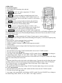
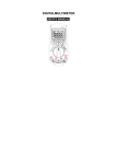
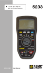
User’s Manual for VC88E
Digital Multimeter
OVERVIEW
The VC88E digital multimeter is a battery-driven 3-¾" digital multimeter. It uses an LCD with a 23 mmhigh display for easy reading. The automatic overload protection feature makes operation more convenient.
The digital multimeter has the function of measuring DCV, ACV, DCA, ACA, resistance, capacitance,
frequency, temperature, both Fahrenheit and Celsius, duty cycle and diode and a continuity performance
test. The meter provides an analog bar and unit symbol display, data holding function (HOLD), relative
value measuring (REL), maximal/minimal value measuring (MAX/MIN), auto/manual range switching
(RANGE), auto power off and warning functions. It uses a double integral A/D converter as its core. It is
an ideal tool for labs, factories, radio-technology and field use.
SAFETY NOTES:
The instrument is designed according to IEC1010 standard (safety standard issued by International
Electro Technical Committee). Please read the following before operation.
1. A voltage of less than 36V is a control and safety voltage. When measuring voltage higher than
36VDC or, 25VAC, check the connection and the insulation of the test leads and probes to avoid
electric shock.
2. Never apply voltage higher than 1000VDC or 750VAC when measuring.
3. Be careful when measuring a voltage higher than 60VDC or 40VAC.
4. Select the correct function and range to avoid faulty operation.
5. Move the test leads away from test points when switching functions.
6. Never input voltage when measuring current.
7. Never modify the meter’s internal circuits.
8. Code for safety symbols:
= high voltage present;
= GND;
= dual insulation; = refer to manual;
= Low battery
SPECIFICATIONS
1. General features
1-1. Display: LCD;
1-2. Max display: 3999 (3-¾") digits, automatic polarity and unit symbol display.
1-3. Measurement method: double integral A/D conversion;
1-4. Sampling rate: approximately 3 times per sec.
1-5. Over-range display: 'OL' displayed in the highest digit.
1-6. Low battery display
1-7. Working environment: 0°C to 40°C, relative humidity: less than 80%;
1-8. Power supply 2 pieces 1.5V battery 'AAA' 7# battery
1-9. Dimension: 7.5 inches x 3-¾ inches x 1-⅜ inches (length x width x height);
1-10. Weight: approximately one pound (including battery)
1-11. Accessories: test leads, user manual, TP01 temperature probe, rubber holster, FS01 flame
safeguard adapter, carry case, alligator clips with boots and 2 each 1.5V battery.
TECHNICAL FEATURES
2-1. Accuracy: ± (a% × reading data + digits), environment temperature at (23°C±5), relative humidity
less than 75%,
2-2. DC Voltage DCV
Range
Accuracy
Resolution
400mV
±(1.5%+6)
0.1mV
4V
1mV
±(0.5%+6)
40V
10mV
400V
100mV
1000V
±(1.0%+4)
1V
Input impedance 400mV Range 10MΩ, other range is 40MΩ.
2-3. AC Voltage ACV
Range
Accuracy
Resolution
400mV
±(1.5%+6)
0.1mV
4V
1mV
±(0.8%+6)
40V
10mV
400V
100mV
750V
±(1.0%+6)
1V
Input impedance 400mV Range 10MΩ, other range is 40MΩ. Frequency response: mV and 750V
range: 40 to 100Hz, other range: 40 to 400 Hz. Display: Sine wave RMS (Average value response).
2-4. DC Current DCA
Range
Accuracy
Resolution
400uA
0.1µA
4000uA
1µA
±(1.0%+5)
40mA
10µA
400mA
100µA
20A
±(1.2%+10)
10mA
MAX measurement voltage drop: full range mA:1.2VA:100mV Max input current: 20A (within 15
seconds)
2-5. AC Current ACA
Range
Accuracy
Resolution
400uA
0.1µA
4000uA
1µA
±(1.5%+5)
40mA
10µA
400mA
100µA
20A
±(2.0%+15d)
10mA
MAX measurement voltage drop: full range mA: 1.2V A:100mV Max input current: 20A (within 15
seconds) Frequency response 20A range: 40 100Hz,other range:40 to 400Hz
2-6. Resistance Ω
Range
Accuracy
Resolution
400Ω
±(0.8%+5d)
0.1Ω
4kΩ
1Ω
40kΩ
10Ω
±(0.8%+4d)
400kΩ
100Ω
4MΩ
1kΩ
40MΩ
±(1.2%+5d)
10kΩ
Open circuit voltage: 400mV
NOTE: With a reading of less than 400 Ω, place the test leads together to measure the wire resistance,
then subtract it from the actual measurement.
2-7. Capacitance C
Range Accuracy
40nF ±(2.5%+6d)
400nF
±(3.5%+8d)
4µF
40µF
400µF ±(5.0%+8d)
Resolution
1pF
10pF
100pF
1nF
10nF
100nF
2-8. Frequency F
Range
Accuracy
Resolution
100Hz
0.1Hz
1000Hz
1Hz
10kHz
10Hz
±(0.5%+4d)
100kHz
100Hz
1MHz
1kHz
30MHz
10kHz
Input sensitivity:1.0V.
2-9. Diode and continuity performance test
Range Value displayed
Forward voltage drop of diode
Testing condition
Forward DCA is approx. 0.5mA, the backward
voltage is approx 1.5V
Buzzer makes a long sound while resistance
Open circuit voltage is approx. 0.5V
is less than (30±20)Ω
CAUTION: DO NOT INPUT VOLTAGE IN THIS RANGE!
2-10. Temperature
Range
Accuracy
Resolution
-0°C ±(1.0%+4)
-40°C-1000°C 0°C - 400°C ±(1.0%+4) 1°C
+400C ±(1.5%+15)
-750°F ±(0.8%+5)
0°F-1832°F
1°F
+750°F ±(1.5%+15)
Sensor: TP01(K type thermocouple)
CAUTION: DO NOT INPUT VOLTAGE IN THIS RANGE!
OPERATION
4-1. Panel description
1. LCD: displays the measuring value and unit.
2. Function key:
2-1. SELECT key: DC /AC mode, temperature C/F, Diode /
Continuity performance switch.
2-2. RANGE key: select auto range or manual range mode. Auto
range is the normal mode, it will display 'AUTO' symbol. Press it to
change to manual range. Press it more than 2 seconds, it will return to
the auto range mode.
2-3. HOLD key: press it, the presently measured value is held on
LCD and HOLD symbol displays. Press it again, 'HOLD' symbol
disappears, and the meter exits the holding mode.
2-4. REL key: press it, reading clears and goes to relative value
measurement mode. 'REL' symbol displays, press it again, 'REL'
symbol disappears, and the meter exits the relative mode.
2-5. MAX/MIN key: press it, meter goes to 'MAX' mode, it will hold
the max value of measured reading. Press it again, goes to 'MIN' mode, it will hold the minimum value
of measurement. No auto power off and analog bar display in this mode. Press it more than 2 seconds,
it exits MAX/MIN mode.
2-6. Hz/DUTY key: When measuring AC Voltage (Current), press it, meter switches to
Frequency/duty cycle/Voltage(Current). When measuring the Frequency, it will switch frequency/duty
cycle 1 to 99%.
3. Selector Knob: Selects measuring function and range
4. Temperature (positive) and VΩHz terminal
5. Voltage, resistance, frequency, capacitor and temperature terminal
6. COM terminal
7. Less than 400mA current testing terminal and temperature (negative) terminal
8. 20A current terminal
4-2. DCV measurement
1. Insert the black test lead into 'COM' terminal and the red one into 'V/Ω/Hz' terminal.
2. Turn the selector knob to
range;
3. Auto range is the normal mode, it will display 'AUTO' symbol. Press the RANGE key to change to
the manual range mode, 400mV, 4V, 40V, 400V, 1000V range is selective.
4. Connect the leads in parallel across the electric circuit under test, LCD displays polarity and voltage
under test connected by the red test lead.
Note
1. Operator should first set the select knob to the highest range, if operator has no idea about the range
of voltage under test, then select the proper range based on the displayed value. If the LCD displays
'OL', it means the meter is over the maximum value of this range, select a higher range.
2. Never input a voltage over 1000VDC.
3. Be careful while measuring a high voltage. DO NOT touch the high voltage circuit or test leads.
4-3. ACV measurement
1. Insert the black test lead into the 'COM' terminal and the red one into the 'V/Ω/Hz' terminal.
range.
2. Turn the selector knob to
3. Auto range is the normal mode, it will display 'AUTO' symbol. Press the 'RANGE' key to change to
the manual range mode, 400mV, 4V, 40V, 400V, 750V range is selective.
Note: When measuring ACV under auto range mode, pressing the RANGE key will display AC mV
range.
4. Connect the leads in parallel across the electric circuit under test, LCD displays voltage as measured
by the test leads.
Note:
1. Operator should first set the selector knob to the highest range, if operator has no idea about the
range of voltage under test, then select the proper range based on displayed value. If the LCD displays
'OL', it means the meter is over the maximum value of this range, select a higher range.
2. Never input a voltage over 750VAC.
3. Be careful while measuring a high voltage. DO NOT touch the high voltage circuit or leads.
4-4. DCA measurement
1. Insert the black test lead into the 'COM' terminal and the red one into the mA terminal (the Max.
400mA) or into the 20A terminal (the Max.20A).
2. Use the selector knob and set to the proper DCA range, press the DC/AC key to select the
measurement mode. Then, connect the leads in series into the electric circuit under test. LCD
displays current under test.
3. When measuring mA DC through a control jack, use the FS01 adapter between the meter leads and
the control jack. Insertion of leads into adapter is not important. If reading comes back as negative
(─) leads are reversed.
Note:
1. Operator should first set the selector knob to the highest range, if operator has no idea about the
range of current under test, then select the proper range based on the displayed value .
2. If the LCD displays 'OL', it means the current is over range. You need to move the selector knob to
a higher range.
3. Maximum input current is 400mA or 20A based on the terminal the red test lead is inserted into,
too large a current will damage the meter.
4-5. ACA measurement
1. Insert the black test lead into the COM terminal and the red one into the mA terminal (maximum
400mA) or into the 20A terminal (maximum 20A).
2. Use the selector knob to set the proper ACA range, press the DC/AC key to select the measurement
mode, then connect the leads in series to the electric circuit under test. LCD displays current under test.
Note:
1. Operator should first set the selector knob to the highest range, if operator has no idea about the
range of current under test, then select the proper range based on the displayed value.
2. If the LCD displays 'OL', it means the current is over range. You need to select a higher range.
3. Maximum input current is 400mA or 20A based on the terminal the red test lead is inserted into, too
large a current will damage the meter.
4-6. Resistance measurement
1. Insert the black lest lead into the 'COM' terminal and the red lead into the 'V/Ω/Hz' terminal.
2. Turn the selector knob to Ω range.
3. Connect the leads in parallel with the resistance being measured.
3. Auto range is the original mode, press the RANGE key change to the manual range mode.
4. When measuring the actual minimum resistance, short-circuit the test leads first, press the REL
button and then test the resistance, it will now display the actual resistance.
Note:
1. The LCD displays 'OL' when the resistance is over the selected range. When measuring a value over
1MΩ, the reading will take a few seconds to become stable. This is normal for high resistance
measuring.
2. When the input lead is in an open circuit, overload displays 'OL'.
3. When measuring in-circuit resistors, be sure that the power is off and all capacitors are completely
discharged.
4. Never input any voltage while the meter is set for resistance range!
4-7. Capacitance measurement
1. Discharge any capacitor to be tested by shorting the terminals of the capacitor with an insulated
device.
2. Turn the selector knob to ' ' range.
3. Insert the black lest lead into the 'COM' terminal and the red lead into the 'V/Ω/Hz' terminal.
4. If the LCD doesn’t display 0, press the REL button to clear the reading;
5. Place the test leads in parallel with the capacitor being tested. The red test lead is for the positive
pole. The LCD displays the capacitance value.
Note:
1. Never input voltage or current to the 'VΩHz' terminal when measuring capacitance.
2. In order to assure an accurate reading, press the REL button to clear the reading before testing.
3. There is only an auto range mode for testing capacitors.
4. The capacitors must be complete discharged before testing to protect the meter.
5. A reading over the 400uF range will delay 15 seconds.
4-8. Frequency measurement
1. Insert the black lest lead into the 'COM' terminal and the red one into the 'V/Ω/Hz' terminal.
2. Turn the selector knob to the Hz range.
3. Place the test leads to the power source or the load which is to be tested.
4. Press the Hz/DUTY key to switch frequency/duty cycle, it will display the frequency or duty cycle
of the signal source which is tested.
Note:
1. There is only an auto range mode under the frequency mode.
2. The meter can still work if the input is higher than 10Vrms, but the accuracy is not guaranteed.
3. In a noise environment, you should use shielded cable to measure a low signal.
4. When measuring high voltage circuits, no part of your body should touch the high voltage circuit.
5. Never input a voltage higher than 250VDC or AC peak value, or it may damage the meter.
4-9. Diode performance test:
1. Insert the black test lead into the 'COM' terminal and the red one into the 'V/Ω/Hz' terminal (the
polarity of the red lead is '+').
range, press the SELECT key to select the measurement mode.
2. Turn the selector knob to
Connect the test leads to the diode being tested, the red test lead connects to the diode positive polarity,
the black test lead to the diode cathode polarity, the reading is the approximate value of the diode’s
forward voltage drop.
3. With the red test connected to the diode cathode polarity and the black test lead to the diode positive
polarity, the LCD will display 'OL'.
4. This will complete diode testing including forward and backward measurement, if the desired result
isn’t met by performing the above tests, it means the diode is bad.
4-10. Continuity performance test:
1. Insert the black test lead into the 'COM' terminal and the red one into the 'V/Ω/Hz' terminal.
range, press the SELECT key to select the continuity measurement
2. Turn the selector knob to
mode.
3. Place the test leads onto two points of the tested circuit, if the inner buzzer sounds, the resistance is
less than 50Ω.
Note: Never input voltage at “
” range.
4-11. Temperature measurement
1. Turn the selector knob to the °C/°F range.
2. Using the TP01 temperature probe insert the cathode (black pin) of the cold end (free end) of the
probe into the 'mA' terminal jack and the anode (red pin) into the 'VΩHz' terminal. Put the working
end (temperature measurement end) of the thermocouple on the surface or inside the object to be
tested. Read the temperature from the screen, and the data is in Centigrade.
3. Press the SELECT key to select Fahrenheit, the data is in degrees Fahrenheit.
Note:
1. When the input terminal is in ambient air, it will display the ambient temperature.
2. Only use the TP01 probe or the temperature accuracy isn’t guaranteed.
3. Never input voltage at temperature range.
4. Never use the TP01 probe to determine the temperatures of liquids or vapors since it can cause an
internal short circuit in the meter.
4-12. Data holding
1. The presently measured value is held on the LCD and the HOLD symbol displays. Press the HOLD
button again, the HOLD function is cancelled.
4-13. Auto power off
1. When the meter has not been used for about 15 minutes, the built-in buzzer will sound 5 times and
the meter goes into sleeping mode, 1 minute later, the buzzer sounds a long tone 1 time and the meter
powers off. Press any key to restart the power.
4-14. Meter maintenance
The VCVC88E is a high accuracy precision instrument, please do not attempt to modify any of the
internal circuits.
1. Keep the meter away from water, dust and shock.
2. Do not store and operate the meter under extremes of high temperature, high humidity,
combustibles, explosives and strong magnetic areas.
3. Wipe the case with a damp cloth and a mild detergent, do not use abrasives and alcohol.
4. If do not operate the meter for a long time, you should take out the batteries to avoid leakage,
corrosion and damage to the meter.
symbol displays, you should replace the battery following the steps:
5. When the
5-1. Unlock the button and remove the battery case;
5-2. Take out the old batteries and replace with new ones. Alkaline batteries are better and have a
longer service life.
5-3. Fit on the battery case and lock the button;
Note:
1. Never input a voltage value higher than 1000VDC or 750VAC
2. Never measure a voltage with the meter selector knob in the current, resistance, temperature,
capacitance or diode and continuity range.
3. Never use the meter without a battery installed and the back case closed securely.
4-15. Trouble shooting
If the meter does not work properly, check the meter as following:
Fault
Solution
Turn on the power
No reading on LCD Set the HOLD key to a correct mode
Replace battery
signal appears
Replace battery
Large Error Value
Replace battery
These specifications are subject to change without notice.
We hereby will not be responsible for any accident and damage caused by improper operation.
The functions stated in this User Manual cannot be exceeded by special use.
MB-0VC88E-00-FD