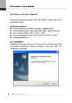
1
www.lsis.com High Precision &Torque Control LS Vector Drive STARVERT iV5 2.2~37kW 3 Phase 200~230V 2.2~800kW 3 Phase 380~460V 5.5~500kW DC Input type Our lives with STARVERT iV5 Optimized Solution for System Drive Control the Crane, Elevator & Continuous line system based on powerful performance High Performance Control system Speed/Torque control, SIN/COS encoder, PM Sensorless, Auto tuning, Endat encoder, Draw/Droop/ Process PID Control, Built-in brake control User-friendly Interface User-friendly keypad, Various field bus option, DriveView management Various Option for System Application Synchronize, SIN/COS encoder(Endat encoder), Extension I/O, EL I/O option ‘We guarantee, your satisfaction will be beyond your expectation’ iV5 series realizes the high precision vector control in entire operational area and its highly precise speed control guarantees a superb control stability in the crane, continuous line and elevator system controls. 220kW UL Certification ISO 14001, ISO 9001 Contents 04 12 13 16 22 24 25 Features Model & Type Standard Specification Wiring Terminal Function I/O Board Loader Use 26 Shifts between each groups and codes in the Loader 27 Function Codes Table 47 Braking Unit and Resistor 49 Dimension 54 Fault Solution and Check 55 Basic configuration Features Optimized Solution for System Drive Control the continuous line as Metal processing/Paper & Paperboard, Crane and Elevator system based on powerful performance System Drive iV5 provides the optimum system operating environment with various function and superior control performance ■ Continuous line Winding/Unwinding System of Metal processing, Paper & Paperboard, Textile, Cable line ■ Customized function for continuous line • Diameter operating ■Diameter operating ■Tension control ■Tension control ■Taper function • Taper function • Splicing control • Flux/Tension control • Inertia compensation • Bobbin random set function • Quick stop • To use Dancer/Load cell • Online set Winding/Unwinding • Over/Under winding • Breakage detecting function • Core fault detecting function 04 iV5 guarantees system safety and reliability with enhanced protection function and various option ■ Crane system iV5 can operate crane system with load balancing, speed/position control, brake control of harbor crane, overhead crane, tower crane, parking system and automation warehouse ■Brake control ■Synchronized operating with speed/position ■Load balancing with droop control Master speed Slave speed Master position Slave position Master speed Slave speed iV5 guarantees comfortable and stable driving with precise position control ■ Elevator system iV5 guarantees stable driving and monitoring the elevator with both optimum speed pattern and position control. ■ Rollback Prevention : Anti-Rollback Function (without external load cell) ■Before Anti-Rollback Algorithm ■Time Chart for Anti-Rollback Function Speed FX Brake ◀ Green : Posion Error between Command & Actual Spd. Brake actual Output ■Before Anti-Rollback Algorithm Rollback Prevention Integral Gain of Speed Controller Proportional Gain of Position Controller Time 05 Features Precise Control Precise speed/torque control, Accurate control with SIN/COS encoder, PM Sensorless control, Auto tuning(at standstill), Draw/Droop/Process PID Control, Brake Control High Performance iV5 guarantees precise speed/position control and synchronous operation in various systems. ■ Speed/Position Synchronized operation ■Speed synchronous operation • Speed/Position synchronizing operation Speed on master-axis Speed on slave-axis • Precision synchronizing operation in 5° • Synchronizing in driving / Synchronizing in starting • Synchronous operation with multiple motors ■Position synchronous operation (with synchronized option card) Position on master-axis Position on slave-axis Speed on master-axis Speed on slave-axis 06 Autotuning ■ Standstill autotuning ■ Rotation autotuning This unique technology of LS allows the autotuning operation to be performed even with the motor shaft directly connected to the load. Especially, this standstill type autotuning is very useful in the lift application because it does not require removal of brake coupling connected to the motor. This type of autotuning has been widely used for the vector control drive. As the name implies, this requires the motor shaft to be free of the coupling for a proper operation. Precise and safe control system ■ Draw/Droop/Process PID control ■Process PID control ■Draw control Draw/Droop/Process PID control is provided for precise control such as tension control, linear velocity control, temperature and pressure control and useful functions easily implemented like Load balancing. ■Droop control Built-in brake control for vertical loading safety ■ Brake Control ■Draw control For applications which have a risk of dropping, for instance elevator and crane system, brake control is built in Extreme precise control ■ SIN/COS encoder option ◀ With SIN/COS encoder option, users can control more precisely than normal encoder SPM, IPM motor control without any sensors ■ Synchronous motor sensorless control With synchronous motor sensorless control functions including initial stimulus position estimation, it perfectly controls SPM, IPM motor without additional sensor. • SPM, IPM motor • Within ±5˚ error estimation • Sensorless 30,000rpm driving Fast reponse within 100msec • A variety of applications such as hydraulic pumps, high-speed compressor, turbo blower ** Please contact us for SPM, IPM motor drive 07 • SPM • IPM Features User Friendly Interface Easy to use with user-centric keypad and removable terminal blocks A variety of communication supported such as LS485, Modbus-RTU, Device Net, Profibus-DP, CC-Link Systematic and efficient management of system through DriveView Convenience Easy to maintain drive/motor parameter via PC ■ Drive View Through DriveView program, drive system can be monitored with PC and managed to maintain drive/motor parameters. • Window based Graphic User Interface (GUI) • LS485, Modbus-RTU • Max 31 drives connection Converter • Reporting • Event logging • Integrated control console • Offline editing • Data upload/download • 4ch oscilloscope • Trigger function 08 User friendly design ■ Easy-to-use keypad By adopting a user-centered operation keypad, parameter setting becomes easier and when applying to system, a variety of required information can be monitored. ■ International standard removable terminal block Wiring/maintenance become easy by international standard acquired terminal block and use also becomes easy by choosing various input/out options depending on intended use Various fieldbus communication options ■Drive View ■Drive integrated console Providing a variety of fieldbus communication options such as LS485, Modbus-RTU, Device Net, Profibus-DP, CC-Link and so forth, users can monitor and operate drives connected with PLC, HMI and other controllers. ■Parameter management Saving parameter file ■Reporting 1 ■Reporting 2 Reporting Inputting detail information 09 ■Oscilloscope/Trigger Triggering Features Wider Applications with Various Options Synchronous option, SIN/COS encoder option, expansion I/O, Elevator dedicated I/O and so forth A wide range of options and applications Variety • Closed/Open loop continuous line control • Load balance function • Diameter operating /Taper function • Splicing control /Inertia compensation • Breakage detecting function • Quick stop • Closed/Open loop continuous line control • Flux/Tension control with PID function • Diameter operating /Taper function • Splicing control /Inertia compensation • Breakage detecting function • Zero velocity control • Quick stop • Closed/Open loop continuous line control • Flux/Tension control with PID function • Diameter operating /Taper function • Splicing control /Inertia compensation • Breakage detecting function • Jog operation at low speed • Quick stop Metal Processing Paper/Paperboard and Textile Automated Warehouse and Parking Machines STARVERT iV5 Winder Crane System Elevators Others • Built-in brake control • Speed/Position synchronous operation • Load balance function • Dedicated DB unit 10 Stage Equipment iV5 Option ■ Synchronization option • Speed/Position synchronizing operation • Consuming current : 300mA • Input frequency : 100kHz • Open collector output • Multiple band operation ■ Elevator I/O • Built-in brake control • Load balance function • Dedicated DB unit • Zero velocity control • Precise control through SIN/COS encoder • Speed/Position synchronous operation • Load balance function • Precise control through SIN/COS encoder • Zero velocity control • Smooth acceleration and deceleration • Elevator dedicated control mode • Geared/gearless elevator operation • Precise control through SIN/COS encoder Elevator master function with on-board option • Optimum speed pattern / no creep speed • Battery operation during blackout • Load cell optimum compensation • Machine tools / press • Cart • Hydraulic pump, high speed compressor, tower blower and so forth • Position sensor/Safety switch input • Car position output • E/L position and sequence control • MC/Brake operation signal output • E/L exclusive connector ■ Device Net • 125/250/500kbps speed • Bus topology • Max. 64 node • Max. 500m (125kbps) • Enhanced online diagnosis function ■ Extension I/O • Analog input : 5 channel • Analog output : 2 channel • Other functions are same as SIO board ■ CC-Link • Max. 10Mbps speed • Customized LS profile • CC Link customized cable • Built-in termination resistor • Remote I/O : each 32 point • Remote register : 4 words ■ LS485/Modbus-RTU • 1200/2400/4800/9600/19200/38400 bps speed Bus, Multidrop link system • Max. 31 node • Max. 1200m period (recommended 700m) ■ Profibus-DP • Max. 12Mbps speed • Max. 32 station • Bus topology • Enhanced online diagnosis function ■ 24V Encoder I/O • 24V encoder • Encoder power fault detection • Other specifications are same as SIO ■ SIN/COS + Endat encoder option • Selectable Endat & Sin/Cos Option • Max. 3,600rpm speed • Enhanced Comfortable feeling in Car - Compatibility with Heidenhain Encorder - ECN413, ECN1313, ERN487, ERN1387 *Note1) Please contact us to control continuous lines with open loop control *Note1) For more than 4 analog inputs, users need to additionally purchase expansion I/O. 11 Model & Type Applicable Motor ranges 2.2kW (3HP) 3.7kW (5HP) 5.5kW (7.5HP) 7.5kW (10HP) 11kW (15HP) 15kW (20HP) 18.5kW (25HP) 22kW (30HP) 30kW (40HP) 37kW (50HP) 45kW (60HP) 55kW (75HP) 75kW (100HP) 90kW (120HP) 110kW (150HP) 132kW (175HP) 160kW (215HP) 220kW (300HP) 280kW (375HP) 315kW (420HP) 375kW (500HP) 500kW (666HP) Mold Type 200V Series 400V Series SV022iV5-2DB(MD) SV037iV5-2DB(MD) SV055iV5-2DB(MD) SV075iV5-2DB(MD) SV110iV5-2DB(MD) SV150iV5-2DB(MD) SV185iV5-2DB(MD) SV220iV5-2DB(MD) SV300iV5-2 SV370iV5-2 SV022iV5-4DB(MD) SV037iV5-4DB(MD) SV055iV5-4DB(MD) SV075iV5-4DB(MD) SV110iV5-4DB(MD) SV150iV5-4DB(MD) SV185iV5-4DB(MD) SV220iV5-4DB(MD) SV300iV5-4 SV370iV5-4 SV450iV5-4 SV550iV5-4 SV750iV5-4 SV900iV5-4 SV1100iV5-4 SV1320iV5-4 SV1600iV5-4 SV2200iV5-4 SV2800iV5-4 SV3150iV5-4 SV3750iV5-4 SV5000iV5-4 SV8000iV5-4 Press Type 12 Standard Specification ■ 200V Class Specifications Type : SV[ ][ ][ ]iV5-2(DB) Maximum applicable [HP] motor ranges [kW] * Note1) Capacity [kVA] * Note2) Rated current [A] Rated output 022 037 055 075 110 150 185 220 300 370 3 5 7.5 10 15 20 25 30 40 50 2.2 3.7 5.5 7.5 11 15 18.5 22 30 37 4.5 6.1 9.1 12.2 17.5 22.5 28.2 33.1 46 55 12 16 24 32 46 59 74 88 122 146 Output speed 0 ~ 3600 (rpm) Output voltage 0 ~ 200V(230V) * Note3) Voltage Rated input 3Ø 200 ~ 230V (-10% ~ +10%) Frequency 50 ~ 60Hz (±5%) Weight [Kg(Ibs)] 6 6 14 14 28 28 28 28 42 42 022 037 055 075 110 150 185 220 300 370 ■ 400V Class Specifications Type : SV[ ][ ][ ]iV5-4(DB) Maximum applicable [HP] 3 5 7.5 10 15 20 25 30 40 50 motor ranges [kW] 2.2 3.7 5.5 7.5 11 15 18.5 22 30 37 Capacity [kVA] 4.5 6.1 9.1 12.2 18.3 22.9 29.7 34.3 46 57 6 8 12 16 24 30 39 45 61 75 28 28 42 Rated current [A] Rated output Output speed 0 ~ 3600 (rpm) Output voltage 0 ~ 380V(480V) * Note3) Weight [Kg(Ibs)] Type : SV[ ][ ][ ]iV5-4(DB) 6 6 14 14 28 28 42 450 550 750 900 1100 1320 1600 2200 2800 3150 3750 5000 Maximum applicable [HP] 60 75 100 120 150 175 215 300 373 420 500 666 motor ranges [kW] 45 55 75 90 110 132 160 220 280 315 375 500 Capacity [kVA] 70 85 116 140 170 200 250 329 416 468 557 732 Rated current [A] 91 110 152 183 223 264 325 432 546 614 731 960 243 380 380 476 Rated output Rated input Output speed 0 ~ 3600 (rpm) Output voltage 380 ~ 460V * Note3) Voltage 3Ø 380 ~ 460V (-10% ~ +10%) * Note4) Frequency Weight [Kg(Ibs)] 50~60Hz (±5%) 63 63 68 98 98 122 *Note1) It represents the output capacity 05 maximum applicable motor in case LG-OTIS 4pole motor is used. *Note2) Rated capacity ( = √3VI) is calculated based on 220V for 200V class, 440V for 400V class. *Note3) Maximum output voltage cannot be generated greater then specified input voltage. *Note4) Derate the rated current by 10% when the input voltage is in the range above 480V. *Note5) Rated current is derated by 10 % above 680 VDC of input voltage. 13 122 175 Standard Specifications ■ Mold type productsʼ electric specifications are same as upper parts (2.2/3.7kW follow below table) Type: SV [ ] [ ] [ ] iV5-2/4DB(MD) 055 075 110 150 185 220 Weight [Kg(Ibs)] 7.7 7.7 13.7 13.7 20.3 20.3 ■ 400V Class (DC power input type) SV [ ] [ ] [ ] iV5-4DC 055 075 110 150 185 220 300 370 450 550 Maximum applicable [HP] 7.5 10 15 20 25 30 40 50 60 75 motor ranges * Note1) [kW] 5.5 7.5 11 15 18.5 22 30 37 45 55 Capacity [kVA] * Note2) 9.1 12.2 18.3 22.9 29.7 34.3 46 57 70 85 Rated current [A] 12 16 24 30 39 45 61 75 91 110 output Speed 0 ~ 3600 (rpm) Voltage 0 ~ 380V(480V) * Note3) Input rated Voltage DC 540 ~ 680V(+10% )* Note5) Drive weight [Kg(Ibs)] 12 (26) 12 (26) 24 (53) 24.5 (54) 25 (55) 25 (55) 38.5 (84) 38.5 (84) 50 (110) 50 (110) SV [ ] [ ] [ ] iV5-4DC 750 900 1100 1320 1600 2200 2800 3150 3750 5000 Maximum applicable [HP] 100 120 150 175 215 300 373 420 500 666 motor ranges * Note1) [kW] 75 90 110 132 160 220 280 315 375 500 Capacity [kVA] * Note2) 116 140 170 200 250 329 416 468 557 732 Rated current [A] 152 183 223 264 325 432 546 614 731 960 343 (756) 343 (756) 466 (1028) output Speed 0 ~ 3600 (rpm) Voltage 0 ~ 380V(480V) * Note3) Input rated Voltage Drive weight [Kg(Ibs)] DC 540 ~ 680V(+10% )* Note5) 55 (121) 79 (174) 79 (174) 98.5 (217) 98.5 (217) 154.5 (340) 206 (454) ■ 400V MRL Specifications SV [ ] [ ] [ ] iV5-4(MRL) 075 110 150 220 Maximum applicable [HP] 10 15 20 30 motor ranges [kW] 7.5 11 15 22 Capacity [kVA] * Note2) 13.7 20.6 27.5 39.6 18 27 36 52 Rated output Rated input Rated current [A] Output speed 0~200 (rpm) Output voltage 380~480V * Note3) Voltage 3Ø 380 ~ 480V (-10% ~ +10%) Frequency Weight [Kg(Ibs)] 50~60Hz (±5%) 14 (30.8) 14 (30.8) *Note1) It represents the output capacity 05 maximum applicable motor in case LG-OTIS 4pole motor is used. *Note2) Rated capacity ( = √3VI) is calculated based on 220V for 200V class, 440V for 400V class. *Note3) Maximum output voltage cannot be generated greater then specified input voltage. *Note4) Derate the rated current by 10% when the input voltage is in the range above 480V. *Note5) Rated current is derated by 10 % above 680 VDC of input voltage. 14 18.7 (41) 19 (41.8) ■ Common Specifications Item Specification Circuit type IGBT adopted voltage type drive Control type Frequency / Speed control accuracy Frequency / Speed Control resolution Response speed Vector V/F Speed ACC/DEC Braking Speed sensor use vector type control Open loop control: V/F control (90-220kW) Analog: ± 0.2% of maximum command speed (25±10℃) Digital: ±0.01% of maximum command speed (0~40℃) Analog: ±0.05% of maximum command speed Digital: 0.01% of maximum command speed 50Hz torque control 3% torque Boost Manual torque boost(0-20%), Automatic torque boost Combination 4 combined of Acc/Dec eleration time V / F pattern Linear, Square, User V/F Time setup 0.00-6000.0 sec (Time unit can be set) Pattern Linear, S-Curve Braking type Dynamic braking using external resistor Braking resistor An external braking resistor is required Braking torque Speed setting 150% Digital setting Multi-step-speed setup by digital input Analog input setting of -10~10V or 4~20mA Setting by options Input 3Channels (AI1, AI2, AI3) Analog input Digital input -10 ~ 10V, 4 ~ 20mA, 10 ~ 0V, 20 ~ 4mA, motor NTC (selectable) Selectable among 9 different multi-function analog inputs FX, RX, BX, RST, P1 ~ P7 Multi function input terminal (P1~P7) can be selected among 27 functions. 2-Channel (AO1, AO2) Analog output Output Digital output Open collector output Protection function -10 ~ 10V output Selective among 31 multi-function analog output functions Multi function digital output: 2channels (1A-1B, 2A-2B) Fault digital output: 1channel (30A-30C, 30B-30C) 1channel (OCI/EG) Over current, Over/Low voltage, Drive overheat, Drive thermal sensor open, Motor over heat, Motor thermal sensor open, Over speed, IGBT gate blocking (BX), Fuse open, Trip by unusual external signal, Encoder error, Communication error, Electronic thermal, Stall prevention (V/F), Over load(V/F), Drive over load Installation environment Environment Ambient temperature Indoor, free of corrosive gas and direct sunlight -10 ~ 40C (Non frozen condition) Ambient humidity Below RH90% (Dew free) Altitude / Vibration Below 1000 meters/ above sea level 5.9㎨ (=0.6G) Cooling method Forced cooling by FAN 15 Wiring AC Input Type 2.2 ~ 22kW (200V/400V)(MD) Brake resistor(option) MCCB ACR MC R B1 B2 V S Supply power 24V Fault reset Multi function input G G Forward run/Stop command Reverse run/Stop command Emergency stop Multi function input1 Multi function input2 Multi function input3 Multi function input4 Multi function input5 Multi function input6 Multi function input7 Common terminal RX BX RST PE Encoder A Phase input 5G A+ A- Encoder B Phase input B+ B- Common terminal FX RA Open collector output P1(MM0) P2(MM1) P3(ATO) P4(FHM) P5(BAT) P6(BRC) P7(MCC) CM GE RB Analog input(-10V~10V) (4~20mA) (0V~10) (4~20mA) Motor NTC Analog input1 Analog input2 Analog input3 Common terminal VREF AI1 AI2 Analog output2 Common out Analog output (-10~10V) Fault digital output (~AC 250V, 1A) (~DC 30V, 1A) 30A Multi function digital output (~AC 250V, 1A) (~DC 30V, 1A) OC1 EG Note) ●: Power terminal ◦: control terminal 16 Encoder output-A Phase Encoder output common terminal Analog output1 30C AI3 5G E AO1 AO2 5G 2A 2B Encoder( line drive) GE 1A 1B Standard voltage Shielded cable Encoder output-B Phase Encoder output common terminal 30B Variable resistor 10㏀, 1/2W IM W T 3phase AC input (220V/440V 50/60Hz) U Multi function open collector output (24V, 50mA) AC Input Type 30 ~ 37kW (200V) 30 ~ 375kW (400V) Brake unit (option) B2 Brake resistor( option) P/B1 Short part MCCB ACR MC P1 P2 G N N R V S Supply power 24V Multi function input1 Multi function input2 Multi function input3 Multi function input4 Multi function input5 Multi function input6 Multi function input7 Common terminal FX RX BX RST 5G A+ A- Encoder B phase input B+ B- P1(MM0) P2(MM1) P3(ATO) P4(FHM) P5(BAT) P6(BRC) P7(MCC) CM Open collector output RA Encoder output-A Phase RB Encoder output-B Phase Encoder output common terminal GE Encoder output common terminal AO1 AO2 5G 30A Analog input(-10V~10V) (4~20mA) (0V~10) (4~20mA) Motor NTC Analog input1 Analog input2 Analog input3 Common terminal VREF AI1 AI2 2A 2B AI3 5G Analog output2 Common out Analog output (-10~10V) Multi function digital output (~AC 250V, 1A) (~DC 30V, 1A) OC1 EG Note) ●: Power terminal ◦: control terminal 17 Analog output1 Fault digital output (~AC 250V, 1A) (~DC 30V, 1A) 30C 1A 1B Standard voltage E GE 30B Variable resistor 10㏀, 1/2W Encoder (Line drive) shielded cable PE Encoder A phase input Common terminal Emergency stop Fault reset Multi function input G G Forward run/Stop command Reverse run/Stop command IM W T 3Phase AC input (220V/440V 50/60Hz) U Multi function open collector output (24V, 50mA) Wiring AC Input Type 500kW (400V) B2 DB resistor (optional) B1 MCCB ACR MC Power source for FAN (220V)(50/60Hz) Aux.Power source for control circuit (220V)(50/60Hz) Potentiometer 10kohm, 1/2W Analog input (10~10V) (-10~10V) (0~10V) (10~0V) (0~20mA) (20~0mA) (Motor NTC/PTC) P2 N U V S G FAN1 Note 2) Insulated transformer Note 2) Insulated transformer Multi function input1 Multi function input2 Multi function input3 Multi function input4 Multi function input5 Multi function input6 FAN2 G Power supply (5V) AC1 Common (0V) 24V Encoder A Phase input AC2 FX RX BX RST Multi function input7 Common P1(MM0) P2(MM1) P3(ATO) P4(FHM) P5(BAT) P6(BRC) P7(MCC) CM Power supply(+10V) VREF Analog input1 Analog input2 AI1 AI2 Common 5G Analog input3 IM W T FWD run/stop command REV run/stop command Emergency stop Fault reset Multi function input P1 N P R 3Phase AC input DB unit (option) G Encoder B Phase input PE 5G B+ B- GE RB AO1 AO2 5G 30B 1A 1B AI3 Encoder output common B Phase encoder pulse output Encoder output common Analog output1 Analog output2 Common out Multi function output (~AC 250V, 1A) (~DC 30V, 1A) OC1 EG Note) ●: Power terminal ◦: control terminal 18 A Phase encoder pulse output Fault relay output (~AC 250V, 1A) (~DC 30V, 1A) 30C 2A 2B Encoder (Line drive) A- GE 30A E A+ RA Open collector output shielded cable Multi function open collector output (24V, 50mA) Analog output (-10~10V) (10~-10V) (0~10V) (10~0V) DC Input Type 5.5~375kW (400V) DC input (540~680VDC) U P(+) W G Aux.Power source for control circuit (220V)(50/60Hz) Note 1) Insulated transformer AC1 24V Power supply (5V) Common (0V) FWD run/Stop command Encoder A Phase input REV run/Stop command RX Encoder B Phase input Fault reset Multi-function input 1 Multi-function input 2 Multi-function input 3 Multi-function input 4 Multi-function input 5 Multi-function input 6 Multi-function input 7 Common Potentiometer 10kohm, 1/2W Analog input (10~-10V) (-10~10V) (0~10V) (10~0V) (0~20mA) (20~0mA) (Motor NTC/PTC) G AC2 FX Emergency stop Power supply (+10V) IM V N(-) BX RST Open collector output P1(MM0) P2(MM1) P3(ATO) P4(FHM) P5(BAT) P6(BRC) CM AI1 Analog input 2 AI2 Analog input 3 AI3 Common 5G A phase encoder pulse output Encoder output Common RB B phase encoder pulse output GE Encoder output Common AO1 Analog output 1 AO2 Analog output 2 Common Analog output (-10~10V) (10~-10V) (0~10V) (10~0V) Fault relay output ( ~ AC 250V, 1A) ( ~ DC 30V, 1A) 30C 30B 1A 1B 2A 2B Encoder (Line Drive Type) RA 30A VREF E GE 5G P7(MCC) Analog input 1 PE 5G A+ AB+ B- Shield Auxiliary relay output ( ~ AC 250V, 1A) ( ~ DC 30V, 1A) OC1 EG Open collector output ( 24V, 50mA) Note) ●: Power terminal ◦: control terminal SIO terminal indication for SV2800~3750iV5: PE PENT, GE G24X ï ï Note 1) It is used when drive control circuit is energized from auxiliary power source (220 VAC) without main power supply. Use insulated transformer to separate from main power supply. (Transformer capacity: above 100VA recommended) 19 Wiring DC Input Type 500kW (400V) Warning) It must be energized AC220V (50/60Hz) to terminal of FAN1 and FAN2 because 30 ~ 500kW-4DC series have a cooling fan for AC power drive and MC. If not, Trip (30~160kW: “FAN/MC PWR”, 220kW: “FAN PWR”) will be occurred. The drive is not operated unless trip is released after AC220V inputs. The recommended order of power input and cutoff is as shown below. (The order of power On: 220VAC P(+)/N(-) Run, The order of power Off: Stop P(+)/N(-) 220VAC) DC input (540~680VDC) FAN and MC Power (220V)(50/60Hz) Warning Insulated transformer P(+) U N(-) V FAN1 W FAN2 G IM G Aux.Power source for control circuit (220V)(50/60Hz) Note 1) Insulated transformer 24V Power supply (5V) Common (0V) FWD run/Stop command AC2 FX Encoder A Phase input REV run/Stop command RX Encoder B Phase input Emergency stop Fault reset Multi-function input 1 Multi-function input 2 Multi-function input 3 Multi-function input 4 Multi-function input 5 Multi-function input 6 Multi-function input 7 Common Potentiometer 10kohm, 1/2W Analog input (10~-10V) (-10~10V) (0~10V) (10~0V) (0~20mA) (20~0mA) (Motor NTC/PTC) AC1 Power supply (+10V) BX RST Open collector output P1(MM0) P2(MM1) P3(ATO) P4(FHM) P5(BAT) P6(BRC) CM AI1 Analog input 2 AI2 Analog input 3 AI3 Common 5G A phase encoder pulse output Encoder output Common RB B phase encoder pulse output GE Encoder output Common AO1 Analog output 1 AO2 Analog output 2 Common Analog output (-10~10V) (10~-10V) (0~10V) (10~0V) Fault relay output ( ~ AC 250V, 1A) ( ~ DC 30V, 1A) 30C 30B 1A 1B 2A 2B Encoder (Line Drive Type) RA 30A VREF E GE 5G P7(MCC) Analog input 1 PE 5G A+ AB+ B- Shield Auxiliary relay output ( ~ AC 250V, 1A) ( ~ DC 30V, 1A) OC1 EG Open collector output ( 24V, 50mA) Note) ●: Power terminal ◦: control terminal Ô Ô Note 1) It is used when drive control circuit is energized from auxiliary power source (220 VAC) without main power supply. Use insulated transformer to separate from main power supply. (Transformer capacity: above 100VA recommended) 20 7.5~22kW (MRL) DB Resistor (optional) MCCB ACR MC 3P AC input (220/440V) (50/60Hz) B1 B2 R U S V T W G G 24V FWD run/Stop command RX Emergency stop BX Fault reset Multi-function input 1 Multi-function input 2 Multi-function input 3 Multi-function input Multi-function input 4 Multi-function input 5 Multi-function input 6 Multi-function input 7 Common Encoder A Phase input FX REV run/Stop command Encoder B Phase input Power supply (5V) Common(0V) RST P1(MM0) Open collector output P2(MM1) P3(ATO) P4(FHM) P5(BAT) P6(BRC) CM Analog input (-10 ~ 10V) (4 ~ 20mA) (10 ~ 0V) (20 ~ 4mA) (Motor NTC) Analog input 1 AI1 Analog input 2 AI2 Analog input 3 AI3 Common 5G RA A phase encoder pulse output GE Encoder output Common RB B phase encoder pulse output GE Encoder output Common AO1 Analog output 1 AO2 Analog output 2 30B 1A 1B OC1 EG Note) ●: Power terminal ◦: control terminal 21 Common Fault relay output ( ~ AC 250V, 1A) ( ~ DC 30V, 1A) 30C 2A 2B Shield E Encoder (Line Drive Type) 5G+ A AB+ B- 30A VREF Power supply (+10V) PE 5G P7(MCC) Potentiometer 10 k ohm, 1/2W PMSM Auxiliary relay output ( ~ AC 250V, 1A) ( ~ DC 30V, 1A) Open collector output ( 24V, 50mA) Analog output (-10~10V) Terminal Function ■ Power Terminal Display Name Description 3Phase AC input connection R, S, T 1) 200V: 200~230V, 50/60Hz AC Input U, V, W 2) 400V: 300~460V, 50/60Hz Cable connection of 3 phase induction motor output G Drive frame earth terminal Earth B1, B2 Braking resistor connection Braking resistor P1, P2 DC reactor and Braking unit P DC Link(+-) terminal N DC Link(-) terminal DC reactor, braking unit and DC link common connection terminal DC Link common connection terminal Braking unit and DC link common terminal ■ Control Circuit Terminals Item Description Display Name FX Forward run command ● "ON" when tied to CM terminal RX Reverse run command ● Stops when FX and RX are ON/OFF simultaneously RST Fault reset P1(MMO) ● Clears the fault condition only when the fault state is removed ● Selectable among the following 27 functions: (Multi step speed selection 1/2/3, JOG run, MOP up/down/Save/Clear, Analog hold, Digital input Main drive, Second function, Speed Acc/Dec time selection, 3-wire operation, External default signal B contact point, Forward rotation prevention, Process PI disable, Timer input, Soft start cancellation, ASR PI Gain selection, ASR P.PI selection, Flux reference selection, Pre-excitation, Speed/Torque control selection, CM Torque limit use, Torque bias VREF COMMON ● "ON" in case of connection between CM and digital AI1 Analog setting power ● Variable resistor use standard voltage(+10V):10㏀ AI2 Current input voltage input ● Voltage input(-10~10V), current input(4~20mA) The motor NTC input is selectable ● Selectable among following 9 functions; (Speed reference, Torque reference, Torque bias, Torque limit, Process PI control reference, Process PI controller feedback, Draw reference, Motor NTC input) Analog input ● Jumper set up use AC voltage input → AI1, AI2: Open , AI3:Left of switch ● Jumper set to use as voltage input voltage input AI3 Motor NTC input 5G COMMON → AI1,AI2: Short ● With motor NTC( OTIS-LG Motor) input, switch direction setup → AI3: Right of switch ● Analog input COMMON terminal 22 ■ Control Circuit Terminals PE 5G A+ AEncoder Input Encoder output Analog Output Digital Output Description Name Classification Display Encoder power Encoder A phase signal B+ BPE 5G PA PB RA GE RB GE AO1 Encoder A phase signal Encoder B phase signal Encoder output-phase A Encoder output common terminal Encoder output-phase B Encoder output common terminal Analog output1 AO2 Analog output2 5G 1A 1B 2A 2B OC1 EG 30A 30B 30C COMMON Encoder B phase signal Encoder power Multi function digital output1(contact point A) Multi function digital output2(contact point B) Multi function open collector output Fault signal A contact point Fault signal B contact point COMMON +5V Line drive power(Jumper set required) 0V ● A and B phase signals of line drive encoder ● To use the line drive type encoder, the "P5 pin" of I/O PCB JP2 should be shorted and then the JP1 switch should be pulled down to "LD" direction ● Jumper setup (factory default) +15V Open collector power (Jumper setup is required) 0V ● A and B phase signals of complementary and open collector type signals ●Short the "P15 pin" of I/O PCB JP2 and then pull up the JP1 switch to "OC" ● Encoder phase A and B output signal (Open collector type) ● Output -10V~+10V ● Selection among following 31 items; (Motor speed, Speed reference1~2, Torque reference1~2,Torque current volume Flux reference, Flux reference volume, Drive output current, Drive output voltage, Motor temperature, DC voltage..) ● COMMON terminal for analog output ● S electable among following 14 items; ( Zero speed detection, speed detection(polarity valid), speed detection(rotation direction invalid), Speed reach, Speed matching, arbitrary torque detection Torque limit feature, Motor overheating signal, Drive overheating signal, Low voltage feature, Drive run signal, Drive regeneration signal, Drive run function, Timer output) ● Activates when the faults occur ● Not available in emergency stop ● Common for A and B digital output ■ Control Circuit Terminal Control Terminal Feature ●Control Terminal Panel Arrangement(Standard Type(SIO) - Non insulated type) 23 I/O Board 1) Encoder wiring and Jumper setup (+15V Complementary or Open collector) I/O PCB version : V1.0 I/O PCB version : V2.0 2) Encoder wiring and Jumper setup (+5V Line drive) I/O PCB version : V1.0 I/O PCB version : V2.0 3) Analog Input Jumper setup (Voltage/ Current/ Motor NTC inputs) I/O PCB version : V1.0 I/O PCB version : V2.0 ●Do not change the jumper set for the encoder type during operation. The Jumper type change during operation results in a serious system damage. Jumpers should be set properly before the drive operation. Warning ●The NTC input of the analog input 3(AI3) is only available with OTIS-LG motors. Use of different type of NTC may cause the motor damage due to overheating. 24 Loader Use ■Data and status display ■Data set up start ■Shift between function groups ■Shifting from group code to the ■Data set up completion upper code ■Decimal point shift ■Only available in case of data setup ■Function code shift ■Shift to next function code ■Data increase in set up mode ■Forward run command key ■Only available with loader operation ■LED is turned on with forward operation ■Blinks during Acc/Deceleration of forward ■Reverse run command key ■Only available, with loader operation operation ■LED is turned ON with reverse run ■Blinks during Acc/Deceleration of reverse run ■Stop command ■Available with the loader operation ■LED is turned on when drive stops its ■Shift to function code ■Shift to previous code ■Data is decreased in set up mode operation ■Blinks when fault occurs ■Reset ■Fault reset ■Loader Use Instruction Classification Display Function Name MODE Mode Key PROG Program Key ENT Enter Key KEY ▲ (up) Up Key ▼ (down) Down Key Shift/ESC Shift/ESC Key REV Reverse run STOP/RESET Stop/Reset Key FWD Forward Key (REV) Reverse run key (STOP/RESET) Stop/Fault display LED (FWD) Forward Run Display Function shift between groups. shift from a group code to upper code. Parameter setting value change. Saving altered setting values. Shift between codes and increase the parameter value. Shift between codes and decrease the parameter value. In case of set up mode, it is operated with the shift key. Operation with ESC key in non-set up mode. Reverse run key. Stop key when drive is on operation. Forward run key. Turns on at reverse operation. Blinks while the drive is on Acc/Deceleration and then turns on the constant speed operation. Turns off when drive stops operation. Blinks when fault occurs. Turns on during forward operation. Acc/Deceleration running modes blink the lamp and it is turned on in the forward operation. 25 Shifts Between Each Groups and Codes in the Loader ■Shifts between each groups and codes in LCD loader The [MODE] key is used for transfer to the other group and the [▲UP] and the [▼down] keys are used to move up and down in the same group. Display group I/O group Parameter group ●The user group and the second group are omitted between shifts of each group. 26 Function group Control group Function Codes Table * ‘ – ‘ mark of communication adrress indicates communication exclusion. * Setting during Drive operation (Yes : possible, No : impossible) ■Display Group [ DIS_ [ ] [ ] ] Code No. Comm. Addr DIS_00 - Code Name Motor Speed/Control Mode OutputTorque/Output Current DIS_01 - User Display 1 DIS_02 DIS_03 - DIS_04 - DIS_05 DIS_06 7106 User Display 2 User Display 3 Process PID Output Ref / FB Faulty Display Display Setting LCD Display 0.0rpm Tq 0.0% Ai1 Value Ai2 Value Ai3 Value Ai4 Value 1) Ai5 Value 1) PreRamp Ref PostRamp Ref ASR Inp Ref Motor Speed Motor SpdEst Speed Dev ASR Out Torque Bias PosTrq Limit NegTrq Limit RegTrq Limit Torque Ref IqeRef Iqe Flux Ref Ide Ref Ide ACR_Q Out ACR_D Out VdeRef VqeRef Out Amps RMS Out Volt RMS Power DC Bus Volt Proc PI Ref Proc PI F/B Proc PI Out MotTemp NTC Inv Temp Inv i2t MP Output Ctrl Mode S/W Version Run Time Terminal In Terminal Opt Terminal Out Run Status Diameter 2) Line SPD CMD 2) Reel SPD 2) PhInOpenLvl Same as the range of ‘DIS_01’ PID Output *xx.x% Faults Disp *Note 1) It is effective only when you use Extended I/O (EXTN_I/O). 2) It is displayed on WEB control Mode. 27 Range Setting Data Unit SPD 0.0A % % % % % rpm rpm rpm rpm rpm rpm % % % -% % % A A % A A V V V V A V kW V % % % deg deg % % % % % V - 0.0% 0.0% 2 (Display ALL) Default Adjustment During Run 1) - - PreRamp Ref Yes DC Bus Volt Terminal In Yes Yes - - Used Yes Function Codes Table ■Digital DIO Group [ DIS_ [ ] [ ] ] Comm. Addr Code Name LCD Display DIO_00 - Jump for quick view Jump Code DIO_01 7201 Multi-function Input t Terminal Code No. P1 definition P1 define 28 Range Setting Data 1 ~ 98 0 (Not Used) 1 (Speed-L) 2 (Speed-M) 3 (Speed-H) 4 (Jog Speed) 5 (MOP Up) 6 (MOP Down) 7 (MOP Clear) 8 (MOP Save) 9 (Analog Hold) 10 (Main Drive) 11 (2nd Func) 12 (Xcel-L) 13 (Xcel-H) 14 (3-Wire) 15 (Ext Trip-B) 16 (Prohibit FWD) 17 (Prohibit REV) 18 (Proc PID Dis) 19 (Timer Input) 20 (SoftStrtCncl) 21 (ASR Gain Sel) 22 (ASR P/PI Sel) 23 (Flux Ref Sel) 24 (PreExcite) 25 (Spd/Trq Sel) 26 (Use Max Trq) 27 (Use Trq Bias) 28 (AuxSpdEnable) 30 (Battery Run) 2) 39 (Synch Disable) 3) 40 (Synch Hod) 3) 41 (LVT Disable) 42 (Dia Hold) 1) 43 (Dia Preset) 1) 44 (CoreSize-L) 1) 45 (CoreSize-H) 1) 46(TensionDisable) 1) 47 (PI Gain Sel) 1) 48 (PID ITerm Clr) 1) 49 (Taper Disable) 1) 50 (Stall Enable) 1) 51 (Boost Enable) 1) 52 (Quick Stop) 1) 53 (Jog Web Fwd) 1) 54 (Jog Web Rev) 1) 55 (Under Wind) 1) 56 (Unwinder) 1) Unit Default Adjustment During Run - - Yes - 0 (Not Used) No Code No. Comm. Addr DIO_02 7202 DIO_03 7203 DIO_04 7204 DIO_05 7205 DIO_06 7206 DIO_07 7207 DIO_08 - Negative function of multi-function input terminal Neg Func. In DIO_09 7209 Multi-function Input LPF time constant DIO_10 - Negative function of multifunction auxiliary output terminal 7229 DIO_42 722A DIO_43 722B DIO_46 722E Multi-function Input t Terminal Multi-function Auxiliary output DIO_41 Code Name LCD Display Range Setting Data Unit Default Adjustment During Run P2 definition P2 define - 0 (Not Used) P3 definition P3 define - 0 (Not Used) No P4 definition P4 define - 0 (Not Used) No P5 definition P5 define - 0 (Not Used) No P6 definition P6 define - 0 (Not Used) No P7 definition P7 define - 0 (Not Used) No 0000000 ~ 1111111 bit 0000000 No Terminal LPF 0 ~ 2000 - 5 Yes Neg Func. Out 00000~ 11111 bit 00000 No Definition of AX1 AX1 Define 0 (Not Used) 1 (INV Ready) 2 (Zero Spd Det) 3 (Spd Det.) 4 (Spd Det(ABS)) 5 (Spd Arrival) 6 (Timer Out) 7 (LV Warn) 8 (Run) 9 (Regenerating) 10 (Mot OH Warn) 11 (Inv OH Warn) 12 (Spd Agree) 13 (Trq Det.) 14 (Trq Lmt Det.) 15 (OverLoad) 16 (Stop) 17 (MC on/off) 18 (Steady) 19 (Brake Output) 25 (WEB Break) 1) 26 (Up To Spd) 1) 27 (False Core) 1) - 0 (Not Used) Yes Definition of AX2 AX2 Define - 0 (Not Used) Yes Definition of OC1 Fault relay mode selection Same as the range of ‘DIO_1’ Same as the range of ‘DIO_41’ OC1 Define Relay Mode 000 ~ 111 29 No - 0 (Not Used) Yes bit 011 Yes Function Codes Table DIO_47 DIO_48 DIO_49 DIO_50 DIO_51 DIO_52 DIO_53 DIO_54 DIO_55 DIO_56 DIO_57 DIO_58 DIO_59 DIO_60 DIO_61 DIO_62 DIO_63 DIO_64 DIO_65 Comm. Addr 722F 7230 7231 7232 7233 7234 7235 7236 7237 7238 7239 723A 723B 723C 723D 723E 723F 7240 7241 DIO_67 7243 DIO_68 7244 DIO_95 725F Overload Code No. Default Adjustment During Run 0.1 ~ 10.0 % 0.5 Yes 0.0 ~ 250.0 0.1 ~ 10.0 0.1 ~ 3600.0 0.1 ~ 3600.0 30 ~ 250 0 ~ 30 0 (No) / 1 (Yes) 30 ~ 250 0 ~ 60 50 ~ 85 0 ~ 10 75 ~ 130 0 ~ 10 % % sec sec % sec % sec deg deg 0.0 0.5 0.1 0.1 150 10 1 (Yes) 180 60 75 5 120 5 Yes Yes Yes Yes Yes Yes Yes Yes Yes Yes Yes Yes Yes MC Timer Off 100 ~ 50000 msec 1000 No MC Timer Off 100 ~ 50000 msec 1000 No 1 No bps 9600 No LCD Display Zero speed detection level Zero speed detection band Speed detection level Speed detection band Speed arrival band Speed deviation band Torque detection level Torque detection band Timer On delay time Timer Off delay time Warning level Warning time Trip selection Trip level Trip time warning temp. Drive overheat warning band Motor overheat warning temp. Motor overheat warning band ZSD Level ZSD Band SD Level SD Band SA Band SEQ Band TD Level TD Band TimerOn Dly TimerOff Dly OL Level OL Time OLT Select OLT Level OLT Time Temp IH Warn Band MH Warn Temp MH Warn Band MC ON delay time 4) MC OFF delay time 4) Drive station address Setting Data Unit Code Name Inv Number Range 0.0 ~ 480.0 0.1 ~ 10.0 -3600 ~ 3600 rpm % rpm deg deg 10.0 0.5 0 1 ~ 250 0 (1200) Yes Yes Yes 1 (2400) DIO_96 7260 485 BaudRate 485 BaudRate 2 (4800) 3 (9600) 4 (19200) 5 (384000) 0 (None) DIO_97 7261 How to Run at Lost command Lost Command 1 (FreeRun) - 0 (None) No DIO_98 7262 4) Timer 10 ~ 300 sec 10 No 2 (Stop) *Note 1) Displayed WEB Control mode setting. 2) It can be set at 5.5 ~ 22 kW-2/4 class. 3) It will be displayed as CON_02 sets to ‘Synchro’ when Synchronization option board is installed. 4) It will be displayed when the definition of multi-funtion output sets as ‘MC On/Off’. 5) It will be displayed RS-485 communication option board is installed. Refer to the user manual for RS485/Modbus-RTU option board (iP5A/iV5). 30 ■Parameter group [ PAR_ [ ] [ ] ] Code No. Comm. Addr LCD Display - Jump for quick view Jump Code PAR_01 7301 Initialize parameters Para. init PAR_02 PAR_03 PAR_04 PAR_04 - Read parameters Write parameters Parameter write protection Password Para. read Para. write Para. lock Password PAR_07 7307 Motor capacity selection Motor select PAR_08 7308 Motor cap. selection of USER UserMotorSel PAR_09 7309 Motor cooling type Cooling Mtd PAR_10 730A Pulse no. Enc Pulse PAR_11 730B Direction setting Enc Dir Set PAR_12 PAR_13 PAR_14 PAR_15 PAR_17 PAR_18 PAR_19 PAR_20 PAR_21 PAR_22 730C 730D 730E 730F 7311 7312 7313 7314 7315 7316 Error check enabling LPF time constant Error detection time speed Base speed Rated voltage Number of poles Efficiency Rated slip Rated current Enc Err Chk Enc LPF EncFaultTime EncFaultPerc Base Speed Rated Volt Pole number Efficiency Rated-Slip Rated-Curr PAR_23 7317 Input power source selection AC In Volt PAR_24 7318 Auto tuning type selection 2) Auto Tune Type Motor PAR_00 Encoder Code Name Range 1 ~ 38 Setting Data 0 (No) 0 (No) 2 (DIS) 2 (DIS) 4 (PAR) 4 (PAR) 6 (CON) 6 (CON) 8 (AIO) 8 (AIO) 10 (2ND) 10 (2ND) 12 (SYN) 12 (SYN) 14 (SLS) 14 (SLS) 0(No) / 1(Yes) 0(No) / 1(Yes) 0 ~ 255 0 ~ 9999 1 (3.7) 0 (2.2) 3 (7.5) 2 (5.5) 5 (15.0) 4 (11.0) 7 (22.0) 6 (18.5) 9 (37.0) 8 (30.0) 11 (55.0) 10 (45.0) 13 (90.0) 12 (75.0) 14 (110.0) 15 (132.0) 16 (160.0) 17 (220.0) 18 (280.0) 19 (315.0) 20 (375.0) 21 (User Define) 1) 0.7 ~ 500.0 0 (Self-cool) 1 (Forced-cool) 360 ~ 4096 0 (A Phase Lead) 1 (B Phase Lead) 0 (No) / 1 (Yes) 0 ~ 100 0.00 ~ 10.00 0.0 ~ 50.0 100.0 ~ 3600.0 120 ~ 560 2 ~ 12 70.0 ~ 100.0 10 ~ 250 1.0 ~ 1000.0 170 ~ 230 320 ~ 480 31 0 (Rotational) 1 (Standstill) Unit - Default - Adjustment During Run Yes - 0 (No) No - 0(No) 0(No) 0 0 No No Yes Yes kW - No kW 5.5 No - 1 (Forced cool) Yes - 1024 No - 0 (A Phase Lead) No ms sec % rpm V % rpm A 1 (Yes) 1 0.00 25.0 1800.0 4 - No Yes No No No No Yes Yes Yes Yes V - No - 0 (Rotational) Function Codes Table Code No. Comm. Addr PAR_26 PAR_27 PAR_28 PAR_29 PAR_30 PAR_31 PAR_34 PAR_35 PAR_36 PAR_37 PAR_38 731A 731B 731C 731D 731E 731F 7322 7323 7324 7325 7326 Motor PAR_25 Code Name LCD Display Auto tuning range setting 2) Auto Tuning Tuning Torque Motor flux current Motor time constant Leakage inductance Leakage coefficient Stator resistance Encoder pulse multiplication 3) Selection for motor inertia tuning Factor of motor inertia Acc./Dec. time of Inertia tuning Inertia LPF Tune Torque Flux-Curr Tr Ls Lsigma Rs Enc Scale Inertia Tune Inertia J Spd Time Inertia LPF Setting Data Range None ALL1/ALL2 Encoder Test Rs Tuning Lsigma Flux Curr Ls Tuning Tr Tuning Inertia Tuning 4) 10.0 ~ 100.0 70% to 0.0 ~ PAR_22 30 ~ 3000 0.00 ~ 500.00 0.00 ~ 100.00 0.000 ~ 5.000 x1 / x16 / x32 / x64 0 (No) / 1 (Yes) 0.001 ~ 60.000 0.500 ~ 10.000 0.010 ~ 50.000 Unit Default Adjustment During Run - None No % A ms mH mH ohm kg·m sec 70 x1 0 (No) 0.500 0.100 Yes Yes Yes Yes Yes Yes No No Yes No No 2 ms *Note 1) When PAR_07 is set to “User Define”, PAR_08 will be displayed. 2) If PAR_24 (Auto-tuning type selection) is set to No.1 “Standstill”, the order of display in PAR_25 (Auto-tuning range setting) will be None ⇒ ALL ⇒ Rs Tuning ⇒ Lsigma ⇒ If/Tr/Ls Tune. 3) Caution: PAR_33 (Enc Scale) Code is necessary only in the case of installation of SIN/COS Encoder option board, Don’t modify the default value “X1” when not using SIN/COS Encoder board If you modify the value, the normal operation isn’t possible. For any extra information in detail, refer to the option dedicated manual. 4) It will be displayed when PAR_35(Selection for motor inertia tuning) sets as ‘Yes’. 32 ■Function group [ FUN_ [ ] [ ] ] Code No. Comm. Addr LCD Display - Jump for quick view Jump Code FUN_01 7401 RUN/STOP command source selection Run/Stop Src FUN_02 - Speed setting source selection Spd Ref Sel FUN_03 7403 Stop mode selection Stop mode FUN_04 FUN_05 FUN_12 FUN_13 FUN_14 FUN_15 FUN_16 FUN_17 FUN_18 FUN_19 FUN_20 FUN_21 FUN_22 7404 7405 740C 740D 740E 740F 7410 7411 7412 7413 7414 7415 7416 Max. motor speed Min. motor speed 0 1 2 3 4 5 6 7 JOG speed Dwell Speed Dwell Time Max Speed Min Speed 2) Speed 0 Speed 1 Speed 2 Speed 3 Speed 4 Speed 5 Speed 6 Speed 7 Jog Speed Dwell Speed Dwell Time FUN_33 7421 Acc./Dec. reference Speed Acc/Dec Ref FUN_36 7424 S ratio 1 in acceleration start Acc S Start FUN_37 7425 S ratio 2 in acceleration start Acc S End FUN_38 7426 S ratio 1 in acceleration start Dec S Start FUN_39 7427 S ratio 2 in acceleration start Dec S End FUN_40 7428 Time scale of acc./dec. time Time scale FUN_41 FUN_42 FUN_43 FUN_44 FUN_45 FUN_46 FUN_47 FUN_48 7429 742A 742B 742C 742D 742E 742F 7430 Acceleration time 1 Deceleration time 1 Acceleration time 2 Deceleration time 2 Acceleration time 3 Deceleration time 3 Acceleration time 4 Deceleration time 4 Acc Time-1 Dec Time-1 Acc Time-2 Dec Time-2 Acc Time-3 Dec Time-3 Acc Time-4 Dec Time-4 FUN_49 7431 FUN_51 FUN_52 FUN_53 7433 7434 7435 FUN_00 Multi-step speed Code Name Selection about use of zero speed time Dec.time of zero speed Dec. time of emergent stop Initial excitation time of motor Setting Data Range 1 ~ 85 0 (Terminal 1) 1 (Terminal 2) 2 (Keypad) 3 (Option) 0 (Analog) 1 (Keypad1) 2 (Keypad2) 3 (Option) 6 (Line SPD Ref) 1) 7 (Line SPD Opt) 1) Adjustment During Run Yes Unit - Default - - 0 (Terminal 1) No - 1 (Keypad1) No 0 (Decel) 1 (Free-run) - 0 (Decel) No 0.0 ~ Max Speed rpm 0.00 ~ 100.00 sec 400.0 ~ 3600.0 0.0 ~ 500.0 1800.0 0.0 0.0 0.0 0.0 0.0 0.0 0.0 0.0 0.0 100.0 100.0 0.00 0 (Max Speed) No No Yes Yes Yes Yes Yes Yes Yes Yes Yes No No 0.0 No 0.0 No 0.0 No 0.0 No - 0.0 No 0.00 ~ 6000.0 sec 2.00 2) 2.00 2) 3.00 2) 3.00 2) 4.00 2) 4.00 2) 5.00 2) 5.00 2) Yes Yes Yes Yes Yes Yes Yes Yes Use 0 Dec T 0 (No) / 1 (Yes) - 0 (No) Yes 0 Dec Time BX Time PreExct Time 0.00 ~ 6000.0 0.0 ~ 6000.0 0 ~ 10000 sec sec ms 0.00 0.0 0 Yes Yes No 0 (Max Speed) 1 (Ref Speed) 0.0 ~ 50.0 0 (0.01 sec) 1 (0.1 sec) 33 % No Function Codes Table Code No. Comm. Addr Unit ms % Default 1000 0 (No) 150 Adjustment During Run No Yes Yes % 100 Yes PWM Freq 2.5 ~ 10.0 4) kHz Restart after fault reset Power-on Run Delay time before Auto restart Retry Number Overspeed Detection Level Restart Time 5) OverSpdLevel 0 (No) / 1 (Yes) 0 (No) / 1 (Yes) 0 ~ 10 0.0 ~ 60.0 0.00 ~ 10.00 100.0 ~ 130.0 0.00 ~ 2.00 0.00 ~ 30.00 0.0 ~ 500.0 0.0 ~ 150.0 0.00 ~ 30.00 0.0 ~ 500.0 0 (No) / 1 (Yes) 600(300) ~ 800(400) 0.0 ~ 500.0 0.0 ~ 300.0 20 ~ 30000 2.5 ~ 200.0 12 ~ PAR_18 0 (No) / 1 (Yes) 2.0 ~ 100.0 0 (No) / 1 (Yes) 0.0~500.0 0~1 0.00 ~ 600.00 0.00 ~ 600.00 sec sec % sec sec rpm % sec rpm V rpm % ms rpm V V rpm sec sec 0(Absolute) 1(Relative) - LCD Display 7436 7437 7438 Hold time Electronic thermal level for 1 minute Electronic thermal level for continuous Hold Time ETH Select ETH 1 min FUN_33 7439 Switching frequency select ETH Cont FUN_58 743A selection FUN_59 FUN_60 FUN_61 FUN_62 FUN_63 FUN_64 FUN_65 FUN_66 FUN_67 FUN_68 FUN_69 FUN_70 FUN_71 FUN_72 FUN_73 FUN_74 FUN_75 FUN_76 FUN_77 FUN_78 FUN_79 FUN_80 FUN_81 FUN_82 FUN_83 FUN_84 743B 743C 743D 743E 743F 7440 7441 7442 7443 7444 7445 7446 7447 7448 7449 744A 744B 744C 744D 744E 7450 7451 7452 7453 7454 7455 FUN_85 7456 Number of auto restart try Wait time for Restart upon Stop Overspeed Detection Time Electronic thermal level for 1 minute Brake FUN_54 FUN_55 FUN_56 Setting Data Range 100 ~ 10000 0 (No) / 1 (Yes) FUN_56 ~ 200 50 ~ FUN_55 (Only available to 150%) Code Name Open Time 6) Open Speed 6) Open Current 6) Close Time 6) Close Speed 6) Run selection Run voltage level 7) Speed limitation 7) Speed P gain 7) Speed I gain 7) Speed in battery-operated mode 8) RST Restart Retry Delay OverSpd Time BKOpen Time BKOpen Spd Release Curr BKClose Time BKClose Spd RegenAvd Sel RegenAvd Lvl CompFreq Lmt RegenAvd P RegenAvd I Batt. Speed Battery input voltage 8) Check of input phase-open PhInOpenChk Check of output phase-open PhOutOpenChk Calculation method of auxiliary speed AuxSpeedType Dec. time of auxiliary speed AuxDecTime Check level of input phase-open Max. auxiliary speed Acc. time of auxiliary speed Absolute/Relative mode for auxiliary speed Batt. Volt PhInOpenLvl AuxSpeedMax AuxAccTime AuxSpeedMode *Note 1) It will be displayed when WEB control mode is set. 2) It will be displayed when CON_01 is set to Sensorless. 3) A default value of a time of acceleration and deceleration is different from the setting capacity of drive. 4) Minimum/Maximum values are different from the capacity of drive. 5) It will be displayed when FUN_03 (Stop method) is set to ‘Free-run’. 6) It will be displayed when the definition of DIO_41 to DIO_43 (Auxiliary output terminal of multi-funtion) is set to ‘Brake Output’. 7) It will be displayed when FUN_71 is set to ‘Yes’. 8) It can set for only 5.5 ~ 22 kW/2/4 products in case ‘Battery Run’ of multi-function input terminal (P1 ~ P&) is turned On. 34 to drive capacity 0 (No) 0 (No) 0 1.0 0.00 120.0 0.00 0.00 0.0 20.0 0.00 0.0 0 (No) 700(350) 100.0 50.0 500 50.0 48 1 (Yes) 3.0 1 (Yes) 10.0 0 2.00 2.00 0 (Absolute) No Yes Yes Yes Yes No No No No No No No No No No No Yes Yes No No No Yes No Yes No No No No ■Control group [ CON_ [ ] [ ] ] Code No. Comm. Addr LCD Display - Jump for quick view Jump Code CON_01 7501 Control mode setting Control Mode CON_02 - Application mode setting Application CON_03 CON_04 CON_05 CON_06 CON_07 CON_08 CON_09 7503 7504 7505 7506 7507 7508 7509 CON_10 750A CON_11 CON_12 CON_14 CON_15 CON_16 CON_17 CON_18 CON_19 CON_20 750B 750C 750E 750F 7510 7511 7512 7513 7514 CON_21 CON_00 ASR Code Name P Gain 1 I Gain 1 LPF time constant 1 P Gain 2 I Gain 2 LPF time constant 2 Ramp time for ASR gain ASR P Gain1 ASR I Gain1 ASR LPF1 ASR P Gain2 ASR I Gain2 ASR LPF2 ASR RAMP Range 1 ~ 80 1 (Speed) 2 (Torque) 3 (Sensorless) General Vect Elevator 1) Synchro 2) WEB Control 0.1 ~ 200.0 0 ~ 50000 0 ~ 20000 0.1 ~ 200.0 0 ~ 50000 0 ~ 20000 10 ~ 10000 Setting Data Adjustment During Run Yes Unit - Default - - 1 (Speed) No - General Vect No % ms ms % ms ms ms 50.0 300 0 5.0 3000 0 1000 Yes Yes Yes Yes Yes Yes Yes ASR TarSpd 0.0 ~ 3600.0 rpm 0.0 No Proc PID Ref PID Ramp Proc PID Kp Proc PID Ki PROC PID Kd Proc Pos Lmt Proc Neg Lmt Proc Out LPF Proc OutGain -100.0 ~ 100.0 0.00 ~ 600.0 0.0 ~ 999.9 0.0 ~ 100.0 0.0 ~ 100.0 -100.0 ~ 100.0 -100.0 ~ 100.0 0 ~ 500 -250.0 ~ 250.0 % sec % % % % % ms % 0.0 0.00 0.0 0.0 0.0 100 100 0 0.0 Yes No Yes Yes Yes Yes Yes Yes Yes 7515 Type selection Proc PID Src 0 (Base Speed) No CON_22 7516 Speed Set setting 3) PID SpeedSet 1.00 ~ FUN_04 rpm 100.0 No CON_23 7517 Output Enable Proc PID Enb 1 (Enable) - 0 (Disable) No CON_24 CON_25 CON_26 7518 7519 751A Draw quantity Control quantity Hold Time PIDHoldTime Draw % Droop % 0 ~ 10000 ms % % CON_27 751B Base speed Droop Src CON_28 CON_29 CON_30 751C 751D 751E Ramp time Minimum speed Minimum torque Droop Time Droop MinSpd Droop MinTrq 751F CON_32 7520 Droop Torque CON_31 Process ID Target Speed after ASR gain switch-over Reference (Loader) Ramp time P gain I gain D gain Positive limit Negative limit Output LPF time constant Output gain Reference source selection Trq Ref Src Reference (keypad) Torque Ref 0 (Base Speed) 1 (Ref Speed) 2 (SpeedSet) 0 (Disable) 2 (Terminal) -100.0 ~ 100.0 0.0 ~ 100.0 0(Base Spd)/ 1(Ref Spd) 0.00 ~ 600.0 0.0 ~ 3600.0 0.0 ~ 100.0 0 (None) 1 (Analog) 2 (Keypad) 3 (Option) -180.0 ~ 180.0 35 No Yes Yes sec rpm % 1000 0.0 0.0 1 (Ref Speed) 2.00 0.0 0.0 - 0 (None) No % 0.0 Yes No Yes Yes Yes Function Codes Table Code No. Comm. Addr CON_33 7521 CON_34 CON_35 CON_36 7522 7523 7524 CON_37 Code Name LCD Display Setting Data Adjustment During Run Range 0 (Kpd Kpd Kpd) 1 (Kpd Kpd Ax) 2 (Kpd Ax Kpd) 3 (Kpd Ax Ax) 4 (Ax Kpd Kpd) 5 (Ax Kpd Ax) 6 (Ax Ax Kpd) 7 (Ax Ax Ax) 8 (Opt Opt Opt) Unit Default - 0 (Kpd Kpd Kpd) No 0.0 ~ 250.0 % 150.0 Yes 0 (None) 1 (Analog) 2 (Keypad) 3 (Option) - 0 (None) No Trq Lmt Src Limit in forward run Limit in reverse run Limit in regeneration Pos Trq Lmt Neg Trq Lmt Reg Trq Lmt 7525 Bias source selection Trq Bias Src CON_38 CON_39 CON_40 CON_54 CON_75 CON_76 CON_77 CON_78 7526 7527 7528 7536 754B 754C 754D 754E Bias quantity Bias feedforward Balance quantity Speed Search selection Speed Search time 4) Speed Search P gain 4) Speed Search I gain 4) Speed Search LPF 4) Trq Bias Trq Bias FF Trq Balance Speed Search SS Time SS P Gain SS I Gain SS LPF % % % ms % % ms 0.0 0.0 50.0 0100 300 100.0 100.0 33.3 Yes Yes Yes No No Yes Yes Yes CON_79 754F Spd Lmt Src 0.1 ~ Max Speed rpm 1800.0 No CON_80 7550 Speed limit of Speed / Torque switch-over -150.0 ~ 150.0 -150.0 ~ 150.0 0.0 ~ 100.0 0000 ~ 1111 (Bit setting) 10 ~ 60000 1.0 ~ 300.0 1.0 ~ 300.0 0.1 ~ 300.0 SpdLmtBias 100.0 ~ Max Speed rpm 100.0 No Speed Search Torque Limit source selection Speed bias of speed / torque *Note 1) It will be displayed only when the E/L_IO board is installed. 2) It will be displayed only when the SYNC_IO board is installed. 5) It will be displayed when CON_21 (Process PID type) is set to SpeedSet. 6) It will be displayed when CON_01 is set to Sensorless. ■User group [ USR_ [ ] [ ] ] Code No. USR_00 Comm. Addr - USR_01 - USR_02 USR_03 USR_04 - Setting Data Code Name LCD Display Select Code number Initialize to the initial value adequate to the application User data save Recall saved User Data. User Group Data Jump Code Range 1 ~ 67 Macro Init User Define E/L - User Save User Recall User Grp No / Yes No / Yes - - 36 Unit - Default User Define No No - Adjustment During Run Yes No No No No ■Second motor Group [ 2nd_ [ ] [ ] ] Code No. 2nd_00 Comm. Addr - Jump for quick view Jump Code 2nd_01 7801 Control mode setting 2nd Ctl Mode 2nd_02 2nd_04 2nd_05 2nd_06 2nd_07 2nd_08 7802 7804 7805 7806 7807 7808 Max. speed Multi-step speed 0 S ratio 1 in acceleration start S ratio 2 in acceleration end S ratio 1 in deceleration start S ratio 2 in deceleration end 2nd Max Spd 2nd Spd 0 2nd Acc S St 2nd Acc S Ed 2nd Dec S St 2nd Dec S Ed 2nd_09 7809 Acc./Dec. time scale Time scale 2 2nd_10 2nd_11 780A 780B Acceleration time Deceleration time 2nd Acc time 2nd Dec time 2nd_12 780C Cooling method 2nd Cool Mtd 2nd_13 780D Encoder pulse no. 2nd Enc # 2nd_14 780E Encoder direction setting 2nd Enc Dir 2nd_15 780F Encoder error check enable 2nd Enc chk 2nd_17 2nd_18 2nd_19 2nd_20 2nd_21 2nd_22 2nd_23 2nd_24 2nd_25 2nd_26 2nd_27 2nd_28 2nd_29 2nd_30 7811 7812 7813 7814 7815 7816 7817 7818 7819 781A 781B 781C 781D 781E 2nd_35 7823 2nd_36 7824 2nd_37 7825 Encoder LPF time constant Base speed Capacity selection User defined motor selection Rated voltage Number of poles Efficiency Rated slip Rated current Flux current Motor time constant Leakage inductance Leakage coefficient Stator resistance Electronic thermal level for 1 minute 1) Electronic thermal continuous level 1) Inertia coefficient 2nd Motor Code Name LCD Display Setting Data Unit - Default - Adjustment During Run Yes - 1 (Speed) No rpm rpm 1800.0 0.0 No Yes 0.0 ~ 50.0 % 0.0 No 0 (0.01 sec) 1 (0.1 sec) - 0 (0.01 sec) No 0.00 ~ 6000.0 sec 10.00 Yes - 0 (Self-cool) Yes - 1024 No Range 1 ~ 37 1 (Speed) 2 (Torque) 400.0 ~ 3600.0 0.0 ~ 2nd_02 2nd Enc LPF 2nd BaseSpd Motor select UserMotorSel 1) 2nd R-Volt 2nd Pole # 2nd Mot Eff. 2nd R-Slip 2nd R-Curr 2nd Flx Cur 2nd Mot Tr 2nd Mot Ls 2nd Mot sLs 2nd Mot Rs 0 (Self-cool) 1 (Forced-cool) 360 ~ 4096 0 (A Phase Lead) 1 (B Phase Lead) 0 (No) 1 (Yes) 0 ~ 100 300.0 ~ 3600.0 Refer to ‘PAR_07’ 0.7 ~ 500 120 ~ 560 2 ~ 12 70 ~ 100 10 ~ 250 1.0 ~ 450.0 0.0 ~ 70% of 2nd_22 30 ~ 3000 0.00 ~ 500.00 0.00 ~ 100.00 0.000 ~ 5.000 2nd ETH 1min - 0 (A Phase Lead) No - 1 (Yes) No ms rpm kW kW V % rpm A A ms mH mH ohm 1 1800.0 2 (5.5) 5.5 4 - Yes No No No No No Yes Yes Yes Yes Yes Yes Yes Yes 100 ~ 150 % 150 Yes 2nd ETH cont 50 ~ 150 % 100 Yes Inertia 0.001 ~ 60.000 kg·m2 0.072 Yes *Note 1) It will be displayed when FUN_55 ETH Select is set to ‘Yes’. 37 Function Codes Table ■Option Group [ EXT_ [ ] [ ] ] Code No. EXT_00 Comm. Addr - Code Name LCD Display Function code selection Jump Code EXT_01 7601 Mounted option board type Opt B/D EXT_02 7602 Mounted option board version EXT_03 Setting Data Unit - Default - Adjustment During Run Yes - 0 (None) No Opt Version 7603 Station address for the communication with PLC Range 1 ~ 99 0 (None) 1 (DeviceNet) 2 (Synchro) 3 (PLC-GF) 4 (PROFIBUS) 6 (RS485) 1) 7 (MODBUS) 1.0 ~ Station ID 2) 0 ~ 63 - 1 Yes EXT_04 EXT_05 7604 7605 DeviceNet baud rate DeviceNet MAC ID Baud Rate 3) MAC ID 3) kbps - 0 (125) 63 - EXT_06 7606 Read object setting for DeviceNet Out Instance 3) - 0 (20) - EXT_07 7607 Write object settinf for DeviceNet In Instance 3) - 0 (70) - EXT_09 EXT_10 EXT_11 EXT_12 EXT_13 EXT_14 EXT_15 EXT_16 EXT_17 EXT_18 EXT_19 EXT_20 EXT_21 EXT_22 EXT_23 EXT_24 EXT_25 EXT_26 EXT_27 7609 760A 760B 760C 760D 760E 760F 7610 7611 7612 7613 7614 7615 7616 7617 7618 7619 761A 761B Profibus MAC ID Number of option output Option output 1 Option output 2 Option output 3 Option output 4 Option output 5 Option output 6 Option output 7 Option output 8 Number of option input Option input 1 Option input 2 Option input 3 Option input 4 Option input 5 Option input 6 Option input 7 Option input 8 Profi MAC ID Output Num Output 1 5) Output 2 5) Output 3 5) Output 4 5) Output 5 5) Output 6 5) Output 7 5) Output 8 5) Input Num Input 1 6) Input 2 6) Input 3 6) Input 4 6) Input 5 6) Input 6 6) Input 7 6) Input 8 6) HEX HEX HEX HEX HEX HEX HEX HEX HEX HEX HEX HEX HEX HEX HEX HEX 1 3 0020 000E 000F 000A 0000 0000 0000 0000 2 0502 0500 0000 0000 0000 0000 0000 0000 Yes Yes Yes Yes Yes Yes Yes Yes Yes Yes Yes No No No No No No No No EXT_30 761E 485 communication mode Parity/Stop 1) 0 (125)/1 (250)/2 (500) 0 ~ 63 0 (20)/ 1 (21) 2 (100)/ 3 (101) 0 (70)/ 1 (71) 2 (110)/ 3 (111) 1 ~ 127 0 ~ 8 5) 0000 ~ FFFF 0000 ~ FFFF 0000 ~ FFFF 0000 ~ FFFF 0000 ~ FFFF 0000 ~ FFFF 0000 ~ FFFF 0000 ~ FFFF 0 ~ 8 6) 0000 ~ FFFF 0000 ~ FFFF 0000 ~ FFFF 0000 ~ FFFF 0000 ~ FFFF 0000 ~ FFFF 0000 ~ FFFF 0000 ~ FFFF 0 (8None/1Stop) 1 (8None/2Stop) 2 (8Even/1Stop) 3 (8Odd/1Stop) - 0 (8None/1Stop) Yes EXT_31 761F Delay Time 1) 2 ~ 1000 ms EXT_32 7620 Delay time of 485 communication response Station address for built-in 485 Int485 St ID - Yes Yes Yes EXT_33 7621 Built-in 485 baudrate Int485 Baud 1 ~ 250 0 (1200 bps) 1 (2400 bps) 2 (4800 bps) 3 (9600 bps) 4 (19200 bps) 5 (38400 bps) 5 2 3 (9600 bps) Yes 38 Ver -.- - No Code No. Comm. Addr Code Name LCD Display EXT_34 7622 Built-in 485 communication mode Int485 Mode EXT_35 7623 Delay time for built-in 485 communication response EXT_36 7624 EXT_37 EXT_99 Setting Data Range 0 (8None/1Stop) 1 (8None/2Stop) 2 (8Even/1Stop) 3 (8Odd/1Stop) Unit Default Adjustment During Run - - Yes Int485 Delay 2 ~ 1000 - 0 (None) Yes Run method when the command of built-in 485 is lost. Int485 LostC 0 (None) 1 (FreeRun) 2 (Stop) - - Yes 7625 Decision time for losing the command of built-in 485 Int485 LostT 1.0 ~ 30.0 - - Yes 7663 Decision time for losing the command of built-in 485 Comm UpDate 4) 0 (No) / 1 (Yes) - 0 (No) No *Note 1) It will be displayed when RS-485 communication option board is installed. 2) It will be displayed when PLC-GF communication option board is installed. 3) It will be displayed when DeviceNet communication option board is installed. 4) It will be displayed when Profibus communication option b oard is installed. 5) From EXT_11 to EXT_18 (Option ouput) are displayed according to the number from EXT_11. 6) From EXT_20 to EXT_27 (Option input) are displayed according to the number from EXT_19. 7) Refer to the appropriate option manual. 39 Function Codes Table ■Analog AIO Group [ AIO_ [ ] [ ] ] Code No. AIO_00 Comm. Addr - AIO_01 7701 AIO_02 Code Name LCD Display Jump Code Multi-function Analog input Ai1 definition Ai1 Define 7702 Source definition Ai1 Source AIO_03 AIO_04 AIO_05 AIO_06 AIO_07 AIO_08 AIO_09 AIO_10 AIO_11 7703 7704 7705 7706 7707 7708 7709 770A 770B Minimum Voltage Minimum Voltage Bias Maximum Voltage Maximum Voltage Gain Minimum Voltage Minimum Voltage Bias Maximum Voltage Maximum Voltage Gain LPF time constant Ai1 In X1 Ai1 Out Y1 Ai1 In X2 Ai1 Out Y2 Ai1 -In X1 Ai1 -Out Y1 Ai1 -In X2 Ai1 -Out Y2 Ai1 LPF AIO_12 770C Command loss Criterion select Ai1 Wbroken AIO_13 770D AIO_14 AIO_15 AIO_16 AIO_17 AIO_18 AIO_19 AIO_20 AIO_21 AIO_22 AIO_23 770E 770F 7710 7711 7712 7713 7714 7715 7716 7717 AIO_24 7718 Multi-function Analog Input Ai2 Torque Select code number Multi-function Analog input Ai2 Definition Source definition Minimum Voltage Minimum Voltage Bias Maximum Voltage Maximum Voltage Gain Minimum Voltage Minimum Voltage Bias Maximum Voltage Maximum Voltage Gain LPF time constant Loss command Criterion select Setting Data Range 1 ~ 83 00 (Not Used) 01 (Speed Ref) 02 (Proc PID Ref) 03 (Proc PID F/B) 04 (Draw Ref) 05 (Torque Ref) 06 (Flux Ref) 07 (Torque Bias) 08 (Torque Limit) 09 (Line SPD Ref) 1) 10 (Tension Ref) 1) 11 (Dancer Ref) 1) 12 (Taper Ref) 1) 13 (Tension F/B) 1) 14 (Diameter) 1) 15 (Diam Preset) 1) 0 (-10 ⇒ 10V) 1 (10 ⇒ -10V) 2 (0 ⇒ 10V) 3 (10 ⇒ 0V) 4 (0 ⇒ 20mA) 5 (20 ⇒ 0mA) 0.00 ~ Ai1 In X2 -10.00 ~ Ai1 Out Y2 0.00 ~ 100.00 0.00 ~ 250.00 Ai1 -In X2 ~ 0.00 Ai1 -Out Y2 ~ 10.00 -100.00 ~ 0.00 -250.00 ~ 0.00 0 ~ 2000 0 (None) 1 (Half of x1) 2 (Below x1) Default - - 0 (Not Used) No - 0 (Not Used) No % % % % % % % % ms 0.00 0.00 100.00 100.00 0.00 10.00 -100.00 -100.00 - Yes Yes Yes Yes Yes Yes Yes Yes - 0 (None) No Ai2 Define Ai2 Source Ai2 In X1 Ai2 Out Y1 Ai2 In X2 Ai2 Out Y2 Ai2 -In X1 Ai2 -Out Y1 Ai2 -In X2 Ai2 -Out Y2 Ai2 LPF Ai2 Wbroken *Note 1) Displayed only when WEB mode setting 40 Adjustment During Run Yes Unit - Refer to AIO_01~12 Comm. Addr AIO_25 7719 AIO_26 771A AIO_27 AIO_28 AIO_29 AIO_30 AIO_31 AIO_32 AIO_33 AIO 34 AIO 34 771B 771C 771D 771E 771F 7720 7721 7722 7723 AIO_36 7724 Code Name Multi-function Analog input Ai3 Definition Multi-function Analog Input Ai3 Code No. AIO_38 AIO_39 AIO_40 AIO_41 AIO_42 AIO_43 AIO_44 AIO_45 AIO_46 AIO_47 AIO_48 Ai3 Source Minimum Voltage Minimum Voltage Bias Maximum Voltage Maximum Voltage Gain Minimum Voltage Minimum Voltage Bias Maximum Voltage Maximum Voltage Gain Input LPF time constant Ai3 In X1 Ai3 Out Y1 Ai3 In X2 Ai3 Out Y2 Ai3 -In X1 Ai3 -Out Y1 Ai3 -In X2 Ai3-Out Y2 Ai3 LPF Multi-function Analog input Ai4 Definition 1) Source Definition 1) Minimum Voltage 1) Minimum Voltage Bias 1) Maximum Voltage 1) Maximum Voltage Gain 1) Minimum Voltage 1) Minimum Voltage Bias 1) Maximum Voltage 1) Maximum Voltage Gain 1) Output LPF time constant 1) Command loss criterion select 1) AIO_37 7726 7727 7728 7729 772A 772B 772C 772D 772E 772F 7730 Unit Range Refer to AIO_01 ∫ Possible to select NTC motor 17 (Use Mot NTC) Ai3 Define Source Definition Multi-function Analog input Command loss criterion select Setting Data LCD Display 0 (-10 ⇒ 10V) 1 (10 ⇒ -10V) 2 (0 ⇒ 10V) 3 (10 ⇒ 0V) - Default Adjustment During Run 0 (Not Used) No 0 (-10 ⇒ 10V) No Ai3 Wbroken Ai4 Define Refer to AIO_03~12 Ai4 Source Ai4 In X1 Ai4 Out Y1 Ai4 In X2 Ai4 Out Y2 Ai4 -In X1 Ai4 -Out Y1 Ai4 -In X2 Ai4 -Out Y2 Ai4 LPF Ai4 Wbroken Refer to AIO_01 7731 AIO_50 7732 AIO_51 AIO_52 AIO_53 AIO_54 AIO_55 AIO_56 AIO_57 AIO_58 AIO_59 AIO_60 7733 7734 7735 7736 7737 7738 7739 773A 773B 773C Multi-function Analog Input Ai2 AIO_49 Multi-function Analog input Ai5 Definition 1) ∫ When using EXTN_I/O motor NTC Ai5 Define /PTC function is available at Ai5 0 (Not Used) No 0 (-10 ⇒ 10V) No 17(Use Mot NTC) Source Definition 1) Ai5 Source Minimum Voltage 1) Minimum Voltage Bias 1) Maximum Voltage 1) Maximum Voltage Gain 1) Minimum Voltage 1) Minimum Voltage Bias 1) Maximum Voltage 1) Maximum Voltage Gain 1) Input LPF time constant 1) Command loss criterion select 1) Ai5 In X1 Ai5 Out Y1 Ai5 In X2 Ai5 Out Y2 Ai5 -In X1 Ai5 -Out Y1 Ai5 -In X2 Ai5 -Out Y2 Ai5 LPF Ai5 Wbroken 0 (-10 ⇒ 10V) 1 (10 ⇒ -10V) 2 (0 ⇒ 10V) 3 (10 ⇒ 0V) - Refer to AIO_03~12 41 Function Codes Table Comm. Addr Code Name LCD Display AIO_73 7749 Multi-function Analog input command loss time Time out Multi-function analog Output AO1 Definition AO1 Define AIO_74 774A AIO_75 774B AIO_76 AIO_77 AIO_78 AIO_79 AIO_80 774C 774D 774E 774F 7750 Multi-function Analog Input AO1 Code No. Source Definition AO1 Source Bias Gain Bias Gain Absolute value setting AO1 Bias AO1 Gain AO1 Bias AO1 Gain AO1 ABS 42 Range Setting Data 0.1 ~ 120.0 0 (Not Used) 1 (Ai1 Value) 2 (Ai2 Value) 3 (Ai3 Value) 4 (Ai4 Value) 2) 5 (Ai5 Value) 2) 7 (PreRamp Ref) 8 (PostRamp Ref) 9 (ASR Inp Ref) 11 (Motor Speed) 12 (Motor SpdEst) 3) 13 (Speed Dev) 14 (ASR Out) 15 Torque Bias 16 (PosTrq Limit) 17 (NegTrq Limit) 18 (RegTrq Limit) 19 (Torque Ref) 20 (IqeRef) 21 (Iqe) 22 (Flux Ref) 23 (IdeRef) 24 (Ide) 25 (ACR_Q Out) 26 (ACR_D Out) 27 (VdeRef) 28 (VqeRef) 29(Out Amps RMS) 30 (Out Volt RMS) 31 (Power) 32 (DC Bus Volt) 33 (Proc PI Ref) 34 (PROC PI F/B) 35 (Proc PI Out) 36 (Line Speed) 1) 37 (Tension Out) 1) 38 (Diameter) 1) 39 (MotNTC Temp) 40 (Inv Temp) 41 (Inv i2t) 0 (-10 ⇒ 10V) 1 (10 ⇒ -10V) 2 (0 ⇒ 10V) 3 (10 ⇒ 0V) -100.0 ~ AIO_77 0.0 ~ 500.0 AIO_79 ~ 0.0 0.0 ~ -500.0 0 (No) / 1 (Yes) Unit Default Adjustment During Run sec 1.0 No - 0 (Not Used) No - 0 (-10 ⇒ 10V) No % % % % - 0.0 100.0 0.0 -100.0 0 (No) No No Yes Yes No AIO_81 AIO_82 AIO_83 AIO_84 AIO_85 AIO_86 AIO_87 Comm. Addr 7751 7752 7753 7754 7755 7756 7757 Code Name Multi-function Analog Input AO1 Code No. Definition Source Definition Bias Gain Bias Gain Absolute value setting LCD Display Setting Data Range AO2 Define AO2 Source AO2 Bias AO2 Gain AO2 Bias AO2 Gain AO2 ABS Unit Default Adjustment During Run Refer to AIO_74~78 *Note 1) Displayed only when WEB mode setting. 2) It is available when Extension I/O (EXTN_I/O) is applied. 3) It will be displayed when CON_01 is set to ‘Sensorless’. ■Sensorless control Group [ SLS_ [ ] [ ] ] Code No. SLS_00 Comm. Addr - SLS_01 7D01 SLS_02 SLS_03 SLS_04 SLS_05 SLS_06 SLS_07 SLS_08 SLS_09 SLS_10 SLS_11 SLS_12 SLS_13 SLS_14 SLS_15 SLS_16 SLS_17 SLS_18 SLS_19 SLS_20 SLS_21 SLS_22 SLS_23 7D02 7D03 7D04 7D05 7D06 7D07 7D08 7D09 7D0A 7D0B 7D0C 7D0D 7D0E 7D0F 7D10 7D11 7D12 7D13 7D14 7D15 7D16 7D17 Default Adjustment During Run Yes 100 ~ 60000 ms 500 Yes 0.1 ~ 999.9 0.0 ~ 999.9 1.0 ~ 600.0 0.1 ~ 999.9 0.1 ~ 999.9 0 ~ 20000 0.1 ~ 999.9 0.1 ~ 999.9 0 ~ 20000 10 ~ 10000 0.0 ~ 3600.0 0.1 ~ 999.9 0.1 ~ 999.9 10.0 ~ 3000.0 0 (No) / 1 (Yes) 0 ~ 10.0000 0 ~ 10.0000 0 ~ 10.0000 0 ~ 10.0000 0.0000 ~ 6.5535 0.0000 ~ 6.5535 100.0 ~ 200.0 % % 100.0 100.0 20.0 100.0 100.0 0 50.0 50.0 0 1000 0.0 100.0 100.0 1200.0 1 (Yes) 0.0000 0.0000 0.0000 0.0000 0.0000 0.0000 120.0 Yes Yes Yes Yes Yes Yes Yes Yes Yes Yes No Yes Yes Yes No No No No No No No Yes LCD Display Function code selection Jump Code Range 1 ~ 23 Flux estimation time with sensorless control Flux BD Time FlxEst PGain FlxEst IGain ASR Cut-Off ASR P Gain1 ASR I Gain1 ASR LPF1 ASR P Gain2 ASR I Gain2 ASR LPF2 ASR RAMP ASR TarSpd SpdEst PGain SpdEst IGain ACR Cut-off ZeroAvd Sel SensoredKp SensoredKi SensorlessKp SensorlessKi FluxEst Ref FluxEst Fbk Rs Scale P gain for flux estimation I gain for flux estimation cut-off frequency for sensorless ASR Sensorless ASR P gain 1 Sensorless ASR I gain 1 Sensorless ASR LPF 1 Sensorless ASR P gain 2 Sensorless ASR I gain 2 Sensorless ASR LPF 2 Switch-over ramp for sensorless ASR Sensorless ASR target speed Sensorless P gain Sensorless I gain Cut-off frequency for sensorless ACR Regerneration avoidance selection P gain of sensored speed controller I gain of sensored speed controller P gain of sensorless speed controller I gain of sensorless speed controller Command of flux estimation Feedback of flux estimation Rs scale *Note 1) It will be displayed when CON_01 is set to Sensorless. 43 Setting Data Unit - Code Name % % ms % % ms ms rpm % Function Codes Table ■Function Group [ FUN_ [ ] [ ] ] FUN Group Code No. FUN_00 Function code selection LCD Display Message Jump Code FUN_01 RUN/STOP Command selection RUN/STOP Src FUN_02 Speed reference selection Spd Ref Sel FUN_03 Stop mode Stop Mode FUN_04 FUN_12 FUN_13 FUN_14 FUN_15 FUN_16 FUN_17 FUN_18 FUN_19 FUN_20 FUN_21 FUN_22 FUN_36 FUN_37 FUN_38 FUN_39 FUN_40 FUN_41 FUN_42 FUN_43 FUN_44 FUN_45 FUN_46 FUN_47 Max Speed Speed 0 Speed 1 Speed 2 Speed 3 Speed 4 Speed 5 Speed 6 Speed 7 JOG Speed Dewell speed Dewell time Acc S Start Acc S End Dec S Start Dec S End Acc Time-1 Dec Time-1 Acc Time-2 Dec Time-2 Acc Time-3 Dec Time-3 Acc Time-4 Dec Time-4 FUN_57 Motor Maximum speed Multi-step speed0 Multi-step speed1 Multi-step speed2 Multi-step speed3 Multi-step speed4 Multi-step speed5 Multi-step speed6 Multi-step speed7 JOG speed Dewell speed Dewell time "S" curve rate 1 in acceleration "S" curve rate 2 in acceleration "S" curve rate 1 in deceleration "S" curve rate 2 in deceleration Acc time1 Dec time1 Acc time2 Dec time2 Acc time3 Dec time3 Acc time4 Dec time4 Zero-speed dec time use Zero speed dec time Emergency stop dec time Initial motor magnetizing time Hold time Electronic thermal selection Electronic thermal 1 minute level Electronic thermal successive operation level Drive switching frequency FUN_58 Selecting power-on start Power-on Run FUN_59 Selecting run after trip reset RST Restart FUN_60 FUN_61 Number of auto restart Auto retry delay time Restart delay time after stop command Overspeed error detect level Overspeed error detect time FUN_48 FUN_49 FUN_51 FUN_52 FUN_53 FUN_54 FUN_55 FUN_56 FUN_62 FUN_63 FUN_64 Code Name Use 0 Dec T 0 Dec Time BX Time PreExct Time Hold Time ETH Select ETH 1 min Setting Data Unit Range 1~62 Terminal 1 Terminal 2 Keypad Option Analog Keypad 1 Keypad 2 Option Decel Free-run rpm 400.0~3600.0 rpm 0.0~Max speed rpm 0.0~Max speed rpm 0.0~Max speed rpm 0.0~Max speed rpm 0.0~Max speed rpm 0.0~Max speed rpm 0.0~Max speed rpm 0.0~Max speed rpm 0.0~Max speed rpm 0.0~Max speed rpm 0.00~30.000 % 0.0 ~ 50.0 % 0.0 ~ 50.0 % 0.0~50.0 % 0.0~50.0 sec 0.00~6000.0 sec 0.00~6000.0 sec 0.00~6000.0 sec 0.00~6000.0 sec 0.00~6000.0 sec 0.00~6000.0 sec 0.00~6000.0 sec 0.00~6000.0 Yes No sec 0.00~6000.0 sec 0.0~6000.0 ms 0~10000 ms 100~10000 No Yes % FUN_54~200 Default R Yes Terminal 1 No Keypad 1 No Decel No 1800.0 0.0 0.0 0.0 0.0 0.0 0.0 0.0 0.0 100.0 100.0 100.0 0.0 0.0 0.0 0.0 2.00 2.00 3.00 3.00 4.00 4.00 5.00 5.00 No Yes Yes Yes Yes Yes Yes Yes Yes Yes Yes Yes No No No No Yes Yes Yes Yes Yes Yes Yes Yes No Yes 0.00 0.0 0 1000 Yes Yes No No No Yes 150 Yes ETH Cont 50~FUN_53 % 100 Yes PWM Freq kHz 10.0 No Yes Yes Yes Yes Retry Number Retry Delay 2.5~10.0 No Yes No Yes 0~10 0.0~60.0 sec 0 1.0 Yes Yes Restart time 0.00~10.00 sec 0.00 No Overspd level Overspd time 100.0~130.0 0.00~2.00 % sec 120.0 0.00 No No 44 ■Control Group [CON_ [ ] [ ] ] CON Group Code No. CON_00 Function code selection LCD Display Message Jump Code CON_01 Control mode selection Control Mode CON_02 Drive application mode selection Application CON_03 CON_04 CON_05 CON_06 CON_07 CON_08 CON_09 CON_10 CON_11 CON_12 CON_13 CON_14 CON_15 CON_16 CON_17 CON_18 CON_19 ASR P Gain1 ASR I Gain1 ASR input LPF time constant1 ASR P Gain2 ASR I Gain2 ASR input LPF time constant 2 Ramp time in gain switching Gain switching speed Process PID command( Loader) Process PID position standard Process PID P gain Process PID I gain Process PID D gain Process PID positive limit Process PID negative limit Process PID output LPF time constant Process PID output gain ASR P Gain1 ASR I Gain1 ASR LPF1 ASR P Gain2 ASR I Gain2 ASR LPF2 ASR Ramp ASR TarSpd Proc PID Ref Proc Posi Ref Proc PID Kp Proc PID Kt PROC PID Kd Proc PID Lmt Proc Neg Lmt Proc Out LPF Proc OutGain CON_20 Process PID output enable Proc PID Enb CON_21 CON_22 CON_23 CON_24 CON_25 Process PID Hold time Draw set up percentage Droop control percentage Droop control minimum speed Droop control minimum torque PID Hold time Draw % Droop % Droop MinSPd Droop MinTrd CON_26 Torque reference value selection Trq Ref Src CON_27 Torque reference (Loader) Trq Ref CON_28 Torque limit definition Trq Lmt Src CON_29 CON_30 CON_31 Forward torque limit Reverse torque limit Regenerative torque limit Pos Trq Lmt Neg Trq Lmt Reg Trq Lmt CON_32 Torque bias selection Trq Bias Src Code Name Trq Bias CON_33 Torque bias volume Torque bias compensation volume of friction CON_34 factor Torque balance percentage CON_35 CON_49 Speed search selection Setting Data Unit Range 1 ~ 47 Speed Torque General Vect/ Elevator % 0.0 ~ 200.0 ms 0 ~ 50000 ms 0 ~ 20000 % 0.0 ~ 200.0 ms 0 ~ 50000 ms 0 ~ 20000 ms 10 ~ 10000 rpm 0.0 ~ 3600.0 % -100.0 ~ 100.0 % 0 ~ 65535 % 0.0 ~ 999.9 % 0.0 ~ 100.0 % 0.0 ~ 100.0 % -100.0 ~100.0 % -100.0 ~100.0 ms 0 ~ 500 % -250.0 ~ 250.0 Disable Enable Terminal ms 0~10000 % -100.0 ~ 100.0 % 0.0 ~ 100.0 rpm 0.0 ~ 3600.0 % 0.0 ~ 100.0 None Analog Option % -180.0~180.0 Kpd Kpd Kpd Kpd Kpd Ax Kpd Ax Kpd Kpd Ax Ax Ax Kpd Kpd Ax Kpd Ax Ax Ax Kpd Ax Ax Ax Opt Opt Opt % 0.0 ~ 250.0 % 0.0 ~ 250.0 % 0.0 ~ 250.0 None Analog Keypad Option % -150.0 ~ 150.0 Default Speed R Yes No General Vect 5.0 3000 0 50.0 300 0 1000 0.0 0.0 0 0.0 0.0 0.0 100 100 0 0.0 Yes Yes Yes Yes Yes Yes Yes No Yes No Yes Yes Yes Yes Yes Yes Yes Disable No 0 0.0 0.0 0.0 0.0 No Yes Yes Yes Yes None No 0.0 Yes Kpd Kpd Kpd No 150.0 150.0 150.0 Yes Yes Yes None No 0.0 Yes No Trq Bias FF -150.0 ~ 150.0 % 0.0 Yes Trq Bias F 0.0 ~ 100.0 0000~1111 (Bit set up) % 50.0 Yes 0100 No Speed search 45 Function Codes Table ■User Group [ USR_ [ ] [ ] ] User Group Code Name LCD Display Message USR_00 Function code selection Jump Code USR_01 Initializing as applicable fieldʼs initial value Macro Init ◦ ◦ ◦ ◦ USR_02 User data save User Save ◦ ◦ ◦ ◦ USR_03 Recall saved user data User Recall ◦ ◦ ◦ ◦ USR_04 User group data User Grp ◦ ◦ ◦ ◦ ■2nd function group [ 2nd_ [ ] [ ] ] 2nd Group Control Method I/O Option Vector V/F SIO EIO Code No. 1 ~ 67 Function code selection LCD Display Message Jump Code 2nd_01 2nd motor control mode 2nd Ctl Mode 2nd_02 2dn motor maximum speed 2nd Max Spd 2nd_04 2nd motor multi-step speed 0 2nd Spd 0 0.0 ~ 2nd_02 2nd Acc S St 2nd_09 2nd_10 "S" curve rate 1 in the 2nd motor acceleration "S" curve rate 2 in the 2nd motor acceleration "S" curve rate 1 in the 2nd motor deceleration "S" curve rate 2 in the 2nd motor deceleration The 2nd motor acceleration time The 2nd motor deceleration time 2nd_11 The 2nd motor cooling method 2nd_05 2nd_06 2nd_07 2nd_08 2nd_17 2nd_18 2nd_19 2nd_20 2nd_21 2nd_22 2nd_23 Number of encoder pulse of 2nd motor The 2nd motor encoder direction selection The 2nd motor encoder error check method The 2nd motor encoder LPF Time Constant The 2nd motor rated speed The 2nd motor rated volt The 2nd motor number of poles The 2nd motor efficiency The 2nd motor rated slip The 2nd motor rated current The 2nd motor flux current 2nd_24 The 2nd motor 2nd time constant 2nd_12 2nd_13 2nd_14 2nd_15 2nd_25 2nd_26 2nd_27 2nd_32 2nd_33 The 2nd motor stator inductance The 2nd motor stator leakage factor The 2nd motor stator resistance The 2nd motor electronic thermal 1 minute level The 2nd motor electronic thermal continuous operation level User Define E/L Yes No Yes No R Yes User Define No No No No No No Setting Data Range Unit 1 ~ 33 Speed Torque 400.0 ~ 3600.0 rpm Code No. 2nd_00 Code Name Setting Data Range Unit Default Default R Yes Speed No 1800.0 No rpm 0.0 Yes 0.0 ~ 50.0 % 0.0 No 2nd Acc S Ed 0.0 ~ 50.0 % 0.0 No 2nd Dec S St 0.0 ~ 50.0 % 0.0 No 2nd Dec S Ed 0.0 ~ 50.0 % 0.0 No 2nd Acc time 2nd Dec time 0.00 ~ 6000.0 0.00 ~ 6000.0 Self-cool Forced-cool sec sec 10.00 10.00 Yes Yes Self-cool Yes 2nd Cool Mtd 2nd Enc # 360 ~ 4096 1024 No 2nd Enc dir A(B)Phase Lead No 2nd Enc chk Yes No A Phase Lead Yes No 2nd Enc LPF 0 ~ 100 ms 1 Yes 2nd RatedSpd 2nd R-Volt 2nd Pole # 2nd Mot Eff 2nd R-Slip 2nd R-Curr 2nd Flx Cur 300.0 ~ 3600.0 120 ~ 560 2 ~ 12 70 ~ 100 10 ~ 250 1.0 ~ 450.0 70% of 0.0~2nd_22 rpm V 1800.0 No No No Yes Yes Yes Yes 2nd Mot Tr 30 ~ 3000 ms Yes 2nd Mot Ls 0.00 ~ 500.00 mH Yes 2nd Mot sLs 0.00 ~ 100.00 mH Yes 2nd Mot Rs 0.000 ~ 5.000 ohm Yes 2nd Eth 1min 100 ~ 150 % 150 Yes 2nd Eth cont 50 ~ 150 % 100 Yes *Note) The auto furing method of the 2nd motor should be Same with the (PAR_22) and (PAR_23). 46 % rpm A A 4 Braking Unit and Resistor 1. SV0055iV5-2/4 ~ SV0220iV5-2/4 : Built-in Brake Unit 1) Braking resistor specifications in capacity Resistance values in the table shown below are calculated based on the 150%, 5%ED standard. In case of 10%ED use, resistor with double rated value should be used. resistorsʼ rated watt. Type Applicable Drives BR0800W020J BR01200W015J BR2400W010J BR2400W008J BR3600W005J BR3600W005J BR1000W085J BR1200W060J BR2400W040J BR2400W030J BR3600W020J BR3600W020J ▶ ED 100sec standard. SV 0055iV5-2 DB SV 0075iV5-2 DB SV 0110iV5-2 DB SV 0150iV5-2 DB SV 0185iV5-2 DB SV 0220iV5-2 DB SV 0055iV5-4 DB SV 0075iV5-4 DB SV 0110iV5-4 DB SV 0150iV5-4 DB SV 0185iV5-4 DB SV 0220iV5-4 DB ▶ Resistance value is based on the self-cooling standard. [㏀] 20 15 10 8 5 5 85 60 40 30 20 20 Capacity(5%ED) [W] 800 1200 2400 2400 3600 3600 800 1200 2400 2400 3600 3600 2) Brake resistor wiring Brake resistor has attached a temperature detectable sensor for fire protection. See below when in use. Brake resistor terminal blocks Drive terminals B1, B2 P,BR One of the multi function input terminals, out of P1~P7, of control terminals board is used as defining "External trip signal contact B" P7, CM Operation The contact is ON in normal temperature and opens in overheat. 2. SV0300iV5-2/4 ~ SV0370iV5-2/4, SV0450iV5-4 ~ SV3750iV5-4 ① SV037DBH-2: 37kW/200V Class Braking Unit (10% ED) ② SV037DBH-4: 37kW/400V Class Braking Unit (10% ED) ③ SV075DBH-4: 75kW/400V Class Braking Unit (10% ED) ④ SV075DB-4 : 75kW/400V Class Braking Unit (100% ED) ⑤ SV220DB-4 : 220kW/400V Class Braking Unit (100% ED) - The Combination of two braking unit for 400V class is possible for more than SV900iV5-4 capacity. - When ED is more than 10%, Use the braking unit for 100% ED (Ex: vertical load such as carne, hoist) - When the drive capacity is more than 220kW, use the braking unit for SV2200DB-4 (100% ED). - Refer to description manual included in braking unit product for the use of 100% ED braking unit. 1) Combination of braking unit Drive SV[ ] [ ] [ ] [ ] iV5-2 SV [ ] [ ] [ ] [ ] iV5-4 Braking unit 0300 / 0370 0300 / 0370 0450 / 0550 / 0750 0900 / 1100 / 1320 / 1600 2200 2800 / 3150 / 3750 200V 37kW 1 37kW 1 2 400V 75kW 1 1 2 220kW Note) 1. Example) Combine two braking units of 75kW ~ 400V Class for SV-900iV5-4(90kW) Class. 2.Refer to the Braking Unit user manual that came with the braking unit. ● Terminal functions Terminal name P/B1 N B2 G IN+ INOUT+ OUT 30A/30B/30C Description Connection to drive terminal P2 or P and B2 of braking resistor. Connection to drive terminal N Connection to brake resistor B2 Ground terminal Control connection lint(used when SLAVE MODE) Control connection lint(used when SLAVE MODE) Control connection lint(used when MASTER MODE) Control connection lint(used when MASTER MODE) Fault signal output terminal, when the protection function of braking unit operates. 30A : Contact A, 30B : Contact B, 30C COMMON 47 2) Braking resistor for braking unit 100% of Braking Torque, 10% ED Braking Unit Resistance [Ω] Rated Power [kW] 37kW ~ 200kW 3 5 37kW ~ 400kW 12 5 75kW ~ 400kW 6 10 Refer th extra manual in 75kW ~ 400kW 6 the case of 100% ED braking unit. 200kw ~ 400kW 2 Braking Unit and Resistor ● Display functions Displayed item Description Main power in braking unit turns on the POWER LED. Generally the braking unit is wired to Drive so, once the input POWER main power of drive is on the POWER LED of braking unit turns on. While braking unit operates its normal operation by the motor regenerative energy, RUN the RUN LED blinks. During the braking operation, if the braking unit heat sink is overheated and exceeds its limited value, OHT the overheat protection function operates. This blocks the braking unit signal and then turns on the OHT LED. During the braking operation, if over current flows in the main circuit of braking unit inside then the over OCT current protection function is operated in order to prevent the circuit from over current. The TURN ON signal of braking unit is blocked and then turns on the OCT LED. ■Terminal Block and Braking Unit ■Wiring 1) Single use of Braking unit Inverter Inverter Inverter Power Motor Power Motor Motor within 10m within 10m within 10m Note 1 Note 1 Note 1 within 10m within 10m Braking unit within 10m Braking resistor Inverter 2) Double use of Braking unit m Motor Braking unit Braking resistor Braking unit Braking resistor Inverter Inverter Note 1 Power Motor Power Motor Braking resistor Note 1 Master Braking unit wiring within 2ms wiring within 2ms Main circuit terminal block Control circuit terminal Note 1 Braking resistor Main circuit terminal block Control circuit terminal wiring within 2ms Twist wiring Master Braking unit Braking resistor Master Braking unit wiring within 2ms Braking resistor wiring within 2ms wiring within 2ms Braking resistor Save Braking unit Braking resistor Main circuit terminal block wiring within 2ms Main circuit terminal block Control circuit terminal Control circuit terminal Twist wiring Twist wiring Braking resistor ■Combination of the Braking units and Braking resistors ●30~37kW(200V/400V) Drive Braking unit ●45~55kW(200V) ●45~75kW(400V) Drive SV0037DBH-2 /SV0037DBH-4 Braking resistor 3Ω5kW/12Ω5kW Braking unit 3Ω5kW SV0075DBH-4 제동유닛 Braking resistor Braking resistor 3Ω5kW 12Ω5kW 48 Braking resistor Drive Braking unit SV0037DBH-2 Braking resistor Save Braking unit ●90~160kW(400V) Drive Braking unit Save Braking unit 12Ω5kW Braking unit Braking unit Braking resistor 12Ω5kW SV0075DBH-4 Braking resistor 12Ω5kW 12Ω5kW 12Ω5kW Peripheral Device ● MCCB (Molded Case Circuit Breaker) and MC (Magnetic Contactor) Voltage 200V Class 400V Class Motor [kW] Drive Model MCCB MC 2.2 SV022iV5-2DB UTS100N EBS33c 3.7 SV037iV5-2DB UTS100N EBS33c MC-18b 5.5 SV055iV5-2DB UTS150L EBS33c MC-22b/32a 7.5 SV075iV5-2DB UTS150L EBS53c MC-40a MC-50a MC-12a/12b 11 SV110iV5-2DB UTS150L EBS63c 15 SV150iV5-2DB UTS150L EBS63c MC-50a 18.5 SV185iV5-2DB UTS150L EBS103c MC-65a/75a 22 SV220iV5-2DB UTS150L EBS203c MC-85a/100b 30 SV300iV5-2 UTS150L EBS203c MC-130a/150a 37 SV370iV5-2 UTS400L EBS203c MC-185a 2.2 SV022iV5-4DB UTS100N EBS33c MC-9a/9b 3.7 SV037iV5-4DB UTS100N EBS33c MC-12a/12b 5.5 SV055iV5-4DB UTS100N EBS33c MC-18b 7.5 SV075iV5-4DB UTS150L EBS33c MC-22b 11 SV110iV5-4DB UTS150L EBS33c MC-32a 15 SV150iV5-4DB UTS150L EBS53c MC-40a 18.5 SV185iV5-4DB UTS150L EBS53c MC-40a 22 SV220iV5-4DB UTS150L EBS63c MC-50a 30 SV300iV5-4(380V) UTS150L EBS103c MC-65a/75a 37 SV370iV5-4(380V) UTS150L EBS103c MC-85a 45 SV450iV5-4(380V) UTS150L EBS203c MC-100a/130a 55 SV550iV5-4(380V) UTS400L EBS203c MC-130a/150a 75 SV750iV5-4(380V) UTS400L EBS203c MC-185a 90 SV900iV5-4(380V) UTS400L EBS203c MC-185a 110 SV1100iV5-4(380V) UTS400L EBS403c MC-225a 132 SV1320iV5-4(380V) UTS400L EBS403c MC-265a 160 SV1600iV5-4(380V) UTS400L EBS403c MC-330a 220 SV2200iV5-4(380V) UTS600L EBS603c MC-400a 280 SV2800iV5-4 UTS800L EBS803c MC-500a 315 SV3150iV5-4 UTS800L EBS803c MC-630a 375 SV3750iV5-4 UTS800L EBS803c MC-800a 49 Dimension 9 9 W1 H1 W2 ● Dimensions of each capacity (mm[inches]) Drive Model 7.5 7.5 D1 H2 1) 2.2 ~ 22kW (200V/400V), Mold Type W1 W2 H1 SV022iV5-2/4DB (MD) 284 SV037iV5-2/4DB (MD) 200 180 [11.18] SV055iV5-2/4DB (MD) [7.87] [7.09] 355 SV075iV5-2/4DB (MD) [13.97] SV110iV5-2/4DB (MD) 250 230 385 SV150iV5-2/4DB (MD) [9.84] [9.06] [15.16] SV185iV5-2/4DB (MD) 304 284 460 SV220iV5-2/4DB (MD) [11.97] [11.18] [18.11] H2 D1 269 [10.69] 340 [13.38] 370 [14.57] 445 [17.52] 207 [8.15] 202 [7.95] 221 [8.70] 254 [10.00] L3 W1 W2 W2 2) 5.5 ~ 22kW (200V/400V/DC Input Type) H2 L2 D3 D2 D1 L1 H3 W3 H1 W5 ● Dimensions of each capacity (mm[inches]) Drive Model W1 W2 W3 W4 W5 L1 L2 L3 D1 D2 D3 H1 H2 SV055iV5-2/4DB SV075iV5-2/4DB SV110iV5-2/4DB SV150iV5-2/4DB SV185iV5-2/4DB SV220iV5-2/4DB 234.4 [9.22] 180 [7.08] 180 [7.08] 27.2 [1.07] 27.2 [1.07] 406.2 [15.9] 391.2 [15.4] 7.5 [0.29] 221.1 [8.7] 209.5 [8.24] 75 [2.95] 6 [0.23] Ø6 Ø 12 335 [13.1] 284 [11.1] 284 [11.1] 25.5 [1.00] 25.5 [1.00] 526 [20.7] 509 [20.0] 10 [0.39] 248.6 [9.78] 237 [9.33] 100 [3.93] 7 [0.27] Ø7 Ø 14 50 H3 3) 30 ~STARVERT-iV5 37kW (200V) 30 ~ 75kW (400V) 30 ~ 75kW (DC Input Type) L3 L2 L1 W1 D1 L4 D2 STARVERT-iV5 D3 P2 P1 W2 W3 ● Dimensions of each capacity (mm[inches]) D4 W4 Drive Model W1 W2 W3 W4 L1 L2 L3 D1 D2 D3 D4 P1 P2 SV300iV5-2/4 SV370iV5-2/4 SV450iV5-4 SV550iV5-4 SV750iV5-4 270 [10.6] 270 [10.6] 319 .2 [12.5] 350 [13.7] 635 [25.0] 660 [26.0] 680 [26.7] 120 [4.72] 197 [7.76] 256.6 [10.1] 308.2 [12.1] 16.9 [0.66] 8 [0.31] 275 275 359.6 375 730.6 758.5 780 82.3 189.3 259 326 24.5 10.5 [10.8] [10.8] [14.1] [14.7] [28.7] [29.8] [30.7] [3.24] [7.45] [10.2] [12.8] [0.90] [0.41] STARVERT-iV5 L3 L2 L1 4) 90 ~ 160kW (400V) 90 ~ 160kW (DC Input Type) D1 L2 D2 STARVERT-iV5 D3 W1 ● Dimensions of each capacity (mm[inches]) D4 P2 P1 W2 W3 Drive Model W1 W2 W3 L1 L2 L3 D1 D2 D3 D4 P1 P2 SV900iV5-4 SV1100iV5-4 SV1320iV5-4 SV1600iV5-4 430 [16.9] 430 [16.9] 507 [19.9] 507 [19.9] 530 [20.8] 530 [20.8] 729 [28.7] 949 [37.3] 760 [29.9] 980 [38.5] 780 [30.7] 1000 [39.3] 83.2 [3.27] 95.2 [3.75] 234.6 [9.23] 231.6 [9.12] 286.2 [11.2] 298 [11.7] 335 [13.2] 345 [13.5] 23.5 [0.92] 23.5 [0.92] 8.5 [0.33] 8.5 [0.33] 51 Dimension L3 L2 P1 D1 L4 D2 L1 5) 220kW (400V) 220kW (DC Input Type) W2 W1 W2 W3 L1 L2 L3 L4 D1 D2 D3 D4 P1 P2 540 [21.26] 649 [25.55] 680 [26.77] 922 [36.3] 968.5 [38.13] 998 [39.29] 150 [5.91] 100.2 [3.94] 271 [10.67] 343 [13.5] 403 [15.87] 38 [1.49] 12 [0.47] W1 6) 280~375kW (400V) 280~375kW (DC Input Type) D1 H2 W2 W3 W3 H1 SV2200iV5-4 D4 W3 ● Dimensions of each capacity (mm[inches]) Drive Model D3 P2 W1 W3 W4 ● Dimensions of each capacity (mm[inches]) Drive Model W1 W2 W3 W4 D1 H1 H2 SV2800iV5-4 SV3150iV5-4 SV3750iV5-4 772 [30.39] 922 [6.30] 500 [19.69] 580 [22.83] 13 [0.51] 14 [0.55] 500 [19.69] 580 [22.83] 1140.5 [44.90] 1302.5 [51.28] 1110 [43.70] 1271.5 [50.06] 442 [17.40] 495 [19.49] 52 7) 500kW (400V) 500kW (DC Input Type) D ● Dimensions of each capacity (mm[inches]) H2 H1 W DC has a same dimension as AC. Drive Model W1 W3 H1 D1 SV5000iV5-4 1200 [30.39] 1330 [44.90] 1260 [43.70] 550 [17.40] 8) 7.5 ~ 11kW (MRL) 7 680 666 64.7 97.2 7 7 310 330 53 Dimension 9) 15kW (MRL) 686 7 75.7 108.5 700 7 7 355 375 10) 22kW (MRL) 7 686 100.7 142.2 700 7 7 355 375 54 Fault Solution and Check ■Fault Display Drive faults activate its protection functions which enable the alarm operation and each fault status is displayed in the loader. Refer to table shown below for the LCD loader displays. Protection function LCD Display OC-U Over current OC-V OC-W Description Drive turns off its output when the output current of the drive flows more than 200% of the drive rated current. Drive turns off its output when a ground fault occurs and the ground fault current is more than the internal setting value of the drive. Ground fault protection Ground Fault Over current trip function may protect the drive when a ground fault occurs due to a low ground fault resistance. Drive turns off its output if the DC voltage of the main circuit increases higher than the rated value (200V series : 400V DC, 400V Series : 800V DC) when the motor Over voltage protection Over Voltage decelerates or when regenerative energy flows back to the drive due to a regenerative load. This fault can also occur due to a surge voltage generated at the power supply system. Drive turns off its output if the DC voltage is below the rated level(200V Series: Low voltage protection Low Voltage 200VDC, 400V Series : 400Vdc) because insufficient torque or over heating of the motor can occurs when the input voltage of the drive drops. Drive turns off its output if the output current of drive is over 180% of Over load trip (Over load protection) Over Load motor rated current and over load trip time. ( only applicable to over 90kW drives and also V/F control mode) Drive turns off its output by opening the fuse when something is wrong with Fuse open Fuse Open the main circuit IGBT to protect the wiring from being damaged from short currents Drive turns off its output if the heat sink over heats due to a damaged cooling Drive over heat InvOver Heat fan or an alien substance in the cooling fan by detecting the temperature of the heat sink. Drive turns off its output if the NTC Thermister, which measures Drive NTC thermister open InvThem OP the temperature of drive, is open. Drive turns off its output if the motor is over-heated to protect the motor. Motor over heat MotOver Heat This protective function prevents the motor from over heat. Drive turns off its output if the NTC Thermister, which measures the Motor NTC thermister open MotThem OP motor temperature, is open. Internal electronic thermal of the drive determines the over heating of the motor. If the motor is overloaded the drive turns off the output. Electronic thermal E-Thermal Drive cannot protect the motor when driving a multi-pole motor or when driving multiple motors, so consider thermal relays or other thermal protective devices for each motor. External fault Ext Trip-BThis is used if the user wants to turn off the drive output due to external fault signal. Arm short-U Arm short-V IGBT short Drive turns off its output if IGBT Arm or output shorts occur. Arm Short-W Arm Short-DB Encoder error Encoder Err This is displayed if there is a problem of encoder signal. Used for the emergency stop of the drive. The drive instantly turns off the output BX Protection (Instant cut off) BX when the BX terminal is turned ON, and returns to regular operation when the BX terminal is turned OFF. Take caution when using this function. Motor over speed Over Speed The motor runs exceeding 120% of its maximum default speed. COM Error This is displayed if there is any types of communication errors between Communication error CPU Error the drive main and loader. 55 Basic configuration Proper peripheral devices must be selected and correct connections made to ensure proper operation. An incorrectly applied or installed drive can result in system malfunction or reduction in product life as well as component damage. You must read and understand this manual thoroughly before proceeding. AC source supply Use the power supply within the permissible range of drive input power rating. MCCB or Earth leakage circuit breaker (ELB) Select circuit breakers with care. A large inrush current may flow in the drive at power on. Magnetic contactor Install it if necessary. Installed, do not use it for the purpose of starting or stopping. Otherwise, it could lead to reduction in product life. AC reactor The AC reactor must be used when the power factor is to be improved or the drive is installed near a large power supply system (1000kVA or more and wiring distance within 10m). Installation and wiring To operate the drive with high performance for a long time, install the drive in a proper place in the correct direction and with proper clearances. Incorrect terminal wiring could result in the equipment damage. Ground To motor DC reactor Do not connect a power factor capacitor, surge suppressor or radio noise filter to the output side of the drive. It is required for drives 5.5kW~22kW (200/400V). Not necessary for drives below 3.7kW. Ground 56 Memo 57 Memo 58 59 ● For your safety, please read user's manual thoroughly before operating. ● Contact the nearest authorized service facility for examination, repair, or adjustment. ● Safety Instructions ● Please contact a qualified service technician when you need maintenance. Do not disassemble or repair by yourself! Any maintenance and inspection shall be performed by the personnel having expertise concerned. ©2004.6 LSIS Co.,Ltd. All rights reserved. ■HEAD OFFICE ■Global Network LS Tower, 127, LS-ro, Dongan-gu, Anyang-si, Gyeonggi-do, Korea ■EMEA ■Asia Pacific www.lsis.com +82-2-2034-4901 / [email protected] +82-2-2034-4375 / [email protected] ● LSIS (Middle East) FZE » Dubai, U.A.E. ● Dalian LSIS Co., Ltd. » Dalian, China ● LSIS (Wuxi) Co., Ltd. » Wuxi, China ● LSIS-VINA Co., Ltd. » Hanoi, Vietnam ● LSIS-VINA Co., Ltd. » Hochiminh , Vietnam ● LSIS Tokyo Office » Tokyo, Japan ● LSIS Shanghai Office » Shanghai, China ● Address: LOB 19 JAFZA VIEW TOWER Room 205, Jebel Ali Freezone P.O. Box 114216, Dubai, United Arab Emirates Tel: 971-4-886 5360 Fax: 971-4-886-5361 e-mail: [email protected] Address: No.15, Liaohexi 3-Road, Economic and Technical Development zone, Dalian 116600, China Tel: 86-411-8273-7777 Fax: 86-411-8730-7560 e-mail: [email protected] Address: 102-A , National High & New Tech Industrial Development Area, Wuxi, Jiangsu, 214028, P.R.China Tel: 86-510-8534-6666 Fax: 86-510-522-4078 e-mail: [email protected] Address: Nguyen Khe - Dong Anh - Ha Noi - Viet Nam Tel: 84-4-882-0222 Fax: 84-4-882-0220 e-mail: [email protected] Address: 41 Nguyen Thi Minh Khai Str. Yoco Bldg 4th Floor, Hochiminh City, Vietnam Tel: 84-8-3822-7941 Fax: 84-8-3822-7942 e-mail: [email protected] Address : 16th, Higashi-Kan, Akasaka Twin Tower, 2-17-22, Akasaka, Minato-ku, Tokyo, Japan Tel: 81-3-3582-9128 Fax: 81-3-3582-2667 e-mail: [email protected] Address: Room E-G, 12th Floor Huamin Empire Plaza, No.726, West Yan'an Road Shanghai 200050, P.R. China Tel: 86-21-5237-9977 (609) Fax: 89-21-5237-7191 e-mail: [email protected] LSIS Beijing Office » Beijing, China Address: B-Tower 17FL.Beijing Global Trade Center B/D. No.36, BeiSanHuanDong-Lu, DongCheng-District, Beijing 100013, P.R. China Tel: 86-10-5825-6025,7 Fax: 86-10-5825-6026 e-mail: [email protected] Specifications in this catalog are subject to change without notice due to continuous product development and improvement. 2014. 04 ● LSIS Guangzhou Office » Guangzhou, China ● LSIS Chengdu Office » Chengdu, China ● LSIS Qingdao Office » Qingdao, China Address: Room 1403,14F,New Poly Tower,2 Zhongshan Liu Road,Guangzhou, P.R. China Tel: 86-20-8326-6764 Fax: 86-20-8326-6287 e-mail: [email protected] Address: Room 1701 17Floor, huanminhanjun internationnal Building, No1 Fuxing Road Chengdu, 610041, P.R. China Tel: 86-28-8670-3101 Fax: 86-28-8670-3203 e-mail: [email protected] Address: 7B40,Haixin Guangchang Shenye Building B, No.9, Shandong Road Qingdao 26600, P.R. China Tel: 86-532-8501-6568 Fax: 86-532-583-3793 e-mail: [email protected] STARVERT iV5 (E) 2004. 06/(16) 2013.10 Printed in Korea Pacomkorea