1
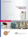
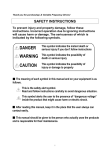
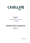
Leader in Electrics & Automation
St ar ver t iV5
High Precision &Torque Control
LG Vector Inverter
5.5~37kW 3 Phase 200~230V, 5.5~220kW 3 Phase 380~460V
Automation Equipment
"" The
The optimum
optimum solution
solution ""
The
The vector
vector control
control LG
LG Starvert
Starvert iV5
iV5 series
series
provides
provides aa full
full satisfaction
satisfaction
for
for all
all the
the needs.
needs.
‘We guarantee, your satisfaction Will be
beyond your expectation’
LG Starvert iV5 series realizes the high
precision vector control in entire
operational area and its highly precise
speed control guarantees a superb control
stability in the elevator controls.
06
Model & Type
05
Features
09
Wiring
07
Standard Specification
13
I/O Board
11
Terminal Function
15
Shifts between each groups and
codes in the Loader
14
Loader Use
24
Braking Unit and
Resistor
16
Function Codes Table
28
Fault Solution and
Check
26
Dimension
29
Basic configuration
LG starvert iV5 series features
the versatile and user-friendly
interface and extended
functional innovation.
"LG inverter is to be evolved
through our state-of-the-art
technologies from now on"
Features
Autotuning
In the application which requires a high torque at low speed, the
electrical parameters of motor should be properly set for an optimal
operation.
LG Vector Controlled Inverter of iV5 has two types of autotuning, which
are standstill type and rotation type, respectively.
LG Inverter iV5 Series
■ Standstill type Autotuning
This unique technology of LG allows the autotuning operation to be
performed even with the motor shaft directly connected to the load.
Especially, this standstill type autotuning is very useful in the lift
application because it does not require removal of brake coupling
connected to the motor.
■ Rotation type Autotuning
This type of autotuning has been widely used for the vector control
inverter. As the name implies, this requires the motor shaft to be free
of the coupling for a proper operation.
Various communication interfaces
iV5 provides various communication interface such as RS 485,
DeviceNET, Profibus-DP and Modbus-RTU. When LG PLC is used as an
upper level controller, it can be easily interfaced to the iV5.
Extended function card (ENC_DIV,DIAO and ELIO)
Option card for the encoder pulse division (ENC_DIV) supports the
encoder with open collector output and can divide the encoder pulse up
to 1/128.
Digital input and Analog signal output card (DIAO) can receive the
binary speed command from PLC or other upper level controller and has
4 channels of analog signal output.
ELIO card enables the lift application software to be available for an
optimized lift operation.
Standard compliances
All starvert iV5 series comply with cUL and UL (Type1) standards.
05
Model & Type
Applicable
Motor ranges
200V Series
400V Series
5.5kW (7.5HP)
SV055iV5-2DB
SV055iV5-4DB
7.5kW (10HP)
SV075iV5-2DB
SV075iV5-4DB
11kW (15HP)
SV110iV5-2DB
SV110iV5-4DB
15kW (20HP)
SV150iV5-2DB
SV150iV5-4DB
18.5kW (25HP)
SV185iV5-2DB
SV185iV5-4DB
22kW (30HP)
SV220iV5-2DB
SV220iV5-4DB
30kW (40HP)
SV300iV5-2DB
SV300iV5-4
37kW (50HP)
SV370iV5-2DB
SV370iV5-4
45kW (60HP)
SV450iV5-4
55kW (75HP)
SV550iV5-4
75kW (100HP)
SV750iV5-4
90kW (120HP)
SV900iV5-4
110kW (150HP)
SV1100iV5-4
132kW (175HP)
SV1320iV5-4
220kW (300HP)
SV1600iV5-4
SV2200iV5-4
Inverter type
Input power specification
Rated capacity
Output power specification
Operation frequency and rated output
Bar-code
Serial number
Displays if DB circuit is built in
Input voltage specification
STARVERT
Maximum applicable motor capacity
iV5 Series
06
Standard Specification
� 200V Class Specifications
Type : SV[ ][ ][ ]iV5-2(DB)
055
075
110
150
185
220
300
370
10
15
20
25
30
40
50
Maximum applicable
[HP]
7.5
motor ranges
[kW]
5.5
7.5
11
15
18.5
22
30
37
Capacity[kVA] * Note2)
9.1
12.2
17.5
22.5
28.2
33.1
46
55
Rated current [A]
24
32
46
59
74
87
122
146
* Note1)
Rated output
Output speed
0 ~ 3600rpm (Vector control)
Output voltage
200 ~ 230V * Note3)
Voltage
Rated input
3∅ 200 ~ 230V (-15% ~ +10%)
Frequency
Weight [Kg(Ibs)]
50 ~ 60Hz (±5%)
14(31)
14(31)
28(62)
28(62)
28(62)
28(62)
43(93)
43(93)
055
075
110
150
185
220
300
370
� 400V Class Specifications
Type : SV[ ][ ][ ]iV5-4(DB)
Maximum applicable
[HP]
7.5
10
15
20
25
30
40
50
motor ranges
[kW]
5.5
7.5
11
15
18.5
22
30
37
Capacity[kVA]
9.1
12.2
18.3
22.9
29.7
34.3
46
57
Rated current [A]
12
16
24
30
39
45
61
75
Rated output
Output speed
0 ~ 3600rpm (Vector)
Output voltage
380 ~ 460V * Note3)
Voltage
Rated input
3∅ 380 ~ 460V (-15% ~ +10%)
Frequency
50 ~ 60Hz (±5%)
Weight [Kg(Ibs)]
14(31)
14(31)
28(62)
28(62)
28(62)
28(62)
45(99)
45(99)
Type : SV[ ][ ][ ]iV5-4(DB)
450
550
750
900
1100
1320
1600
2200
Maximum applicable
[HP]
60
75
100
120
150
175
215
300
motor ranges
[kW]
45
55
75
90
110
132
160
220
Capacity[kVA]
70
85
116
140
170
200
250
329
Rated current [A]
91
110
152
183
223
264
325
432
Rated output
0 ~ 3600rpm (Vector)
Output speed
380 ~ 460V * Note3)
Output voltage
Rated input
3∅ 380 ~ 460V (-15% ~ +10%)
Voltage
50 ~ 60Hz (±5%)
Frequency
Weight [Kg(Ibs)]
63(139)
63(139)
68(150)
98(216)
*Note1) It represents the output capacity 05 maximum applicable motor in case LG-OTIS 4pole motor is used.
*Note2) Rated capacity ( = √
3VI) is calculated based on 220V for 200V class, 440V for 400V class.
*Note3) Maximum output voltage cannot be generated greater then specified input voltage.
07
98(216)
122(269) 122(269) 175(386)
Standard Specifications
� Common Specifications
Item
Specification
Circuit type
Control type
Frequency / Speed
control accuracy
Frequency / Speed
resolution
Control
Response speed
Vector
torque control
V/F
Speed
ACC/DEC
Open loop control: V/F control (90-220kW)
Analog: ± 0.2% of maximum command speed (25±10℃)
Digital: ±0.01% of maximum command speed (0~40℃)
Analog: ±0.05% of maximum command speed
Digital: 0.01% of maximum command speed
50Hz
3%
V / F pattern
Linear, Square, User V/F
torque Boost
Manual torque boost(0-20%), Automatic torque boost
Time setup
0.00-6000.0 sec (Time unit can be set)
Combination
4 combined of Acc/Dec eleration time
Pattern
Braking type
Braking
IGBT adopted voltage type inverter
Speed sensor use vector type control
Linear, S-Curve
Dynamic braking using external resistor
Braking torque
150%
Braking resistor
An external braking resistor is required
Digital setting
Speed setting
Multi-step-speed setup by digital input
Analog input setting of -10~10V or 4~20mA
Setting by options
3Channels (AI1, AI2, AI3)
Input
Analog input
-10 ~ 10V, 4 ~ 20mA, 10 ~ 0V, 20 ~ 4mA, motor NTC (selectable)
Selectable among 9 different multi-function analog inputs
FX, RX, BX, RST, P1 ~ P7
Digital input
Multi function input terminal (P1~P7) can be selected among 27 functions.
2-Channel (AO1, AO2)
Analog output
-10 ~ 10V output
Selective among 31 multi-function analog output functions
Output
Multi function digital output: 2channels (1A-1B, 2A-2B)
Digital output
Open collector output
Fault digital output: 1channel (30A-30C, 30B-30C)
1channel (OCI/EG)
Over current, Over/Low voltage, Inverter overheat, Inverter thermal sensor open,
Protection function
Motor over heat, Motor thermal sensor open, Over speed, IGBT gate blocking (BX), Fuse
open, Trip by unusual external signal, Encoder error, Communication error, Electronic
thermal, Stall prevention (V/F), Over load(V/F), Inverter over load
Installation environment
Ambient temperature
Environment
Ambient humidity
Cooling method
Altitude / Vibration
Indoor, free of corrosive gas and direct sunlight
-10 ~ 40C (Non frozen condition)
Below RH90% (Dew free)
Forced cooling by FAN
Below 1000 meters/ above sea level 5.9㎨ (=0.6G)
08
Wiring
SV 055, 075, 110, 150, 185, 220 iV5-2(DB)
SV 055, 075, 110, 150, 185, 220 iV5-4(DB)
Brake resistor(option)
MCCB
ACR
MC
B1
B2
R
V
S
24V
Fault reset
Multi function input
G
G
Forward run/Stop command
Reverse run/Stop command
Emergency stop
RX
Multi function input7
Common terminal
P7(MCC)
CM
PE
Common terminal
5G
A+
A-
Encoder
B Phase input
BX
RST
P1(MM0)
P2(MM1)
Supply power
Encoder
A Phase input
FX
Multi function input1
Multi function input2
Multi function input3
Multi function input4
Multi function input5
Multi function input6
RA
Open collector
output
P3(ATO)
P4(FHM)
P5(BAT)
P6(BRC)
GE
RB
Analog input(-10V~10V)
(4~20mA)
(0V~10)
(4~20mA)
Motor NTC
Analog input1
Analog input2
Analog input3
Common terminal
VREF
AI1
AI2
E
Encoder output-A Phase
Encoder output common terminal
GE
AO1
Analog output1
AO2
5G
Analog output2
Common out
Multi function digital output
(~AC 250V, 1A)
(~DC 30V, 1A)
2A
2B
OC1
EG
Note ●: Power terminal ○: control terminal
09
Analog output
(-10~10V)
Fault digital output
(~AC 250V, 1A)
(~DC 30V, 1A)
30A
30C
AI3
5G
Encoder( line drive)
Encoder output-B Phase
Encoder output common terminal
1A
1B
Standard voltage
Shielded cable
B+
B-
30B
Variable resistor 10㏀, 1/2W
IM
W
T
3phase AC
input
(220V/440V
50/60Hz)
U
Multi function
open collector output
(24V, 50mA)
Wiring
SV300, 370iV5-2
SV300, 370, 450, 550, 900, 1100, 1320, 1600, 2200iV5-4
Brake unit (option)
B2
G
Brake resistor( option)
P/B1
N
Short part
MCCB
ACR
MC
P1
P2
N
U
R
V
S
W
T
3Phase AC
input
(220V/440V
50/60Hz)
Supply power
PE
Common terminal
5G
A+
AB+
B-
24V
Emergency stop
Fault reset
Multi function input
G
G
Forward run/Stop command
Reverse run/Stop command
Multi function input1
Multi function input2
Multi function input3
Multi function input4
Multi function input5
Multi function input6
Multi function input7
Common terminal
FX
RX
BX
RST
P1(MM0)
P2(MM1)
P3(ATO)
P4(FHM)
P5(BAT)
P6(BRC)
P7(MCC)
CM
Encoder A phase
input
Encoder B phase
input
Open collector
output
Analog input(-10V~10V)
(4~20mA)
(0V~10)
(4~20mA)
Motor NTC
Analog input1
Analog input2
Analog input3
Common terminal
VREF
AI1
AI2
E
RA
Encoder output-A Phase
Encoder output common terminal
RB
Encoder output-B Phase
GE
Encoder output common terminal
AO1
Analog output1
AO2
Analog output2
5G
30A
Common out
Multi function digital output
(~AC 250V, 1A)
(~DC 30V, 1A)
2A
2B
OC1
AI3
5G
EG
Note) ●: Power terminal ○: control terminal
10
Analog output
(-10~10V)
Fault digital output
(~AC 250V, 1A)
(~DC 30V, 1A)
30C
1A
1B
Standard voltage
Encoder (Line drive)
shielded cable
GE
30B
Variable resistor 10㏀, 1/2W
IM
Multi function
open collector output
(24V, 50mA)
Terminal Function
� Power Terminal
Display
Description
Name
3Phase AC input connection
R, S, T
1) 200V: 200~230V, 50/60Hz
AC Input
2) 400V: 300~460V, 50/60Hz
U, V, W
output
Cable connection of 3 phase induction motor
G
Earth
Inverter frame earth terminal
B1, B2
Braking resistor
Braking resistor connection
P1, P2
DC reactor and Braking unit
DC reactor, braking unit and DC link common connection terminal
P
DC Link(+-) terminal
DC Link common connection terminal
N
DC Link(-) terminal
Braking unit and DC link common terminal
� Control Circuit Terminals
Item
Display
Name
FX
Forward run command
● "ON" when tied to CM terminal
RX
Reverse run command
● Stops when FX and RX are ON/OFF simultaneously
RST
Fault reset
P1(MMO)
Description
● Clears the fault condition only when
the fault state is removed
● Selectable among the following 27 functions:
(Multi step speed selection 1/2/3, JOG run, MOP up/down/Save/Clear, Analog hold,
Digital input
Main drive, Second function, Speed Acc/Dec time selection, 3-wire operation,
External default signal B contact point, Forward rotation prevention, Process PI
disable, Timer input, Soft start cancellation, ASR PI Gain selection, ASR P.PI
selection, Flux reference selection, Pre-excitation, Speed/Torque control selection,
CM
Torque limit use, Torque bias
VREF
COMMON
● "ON" in case of connection between CM and digital
AI1
Analog setting power
● Variable resistor use standard voltage(+10V):10㏀
● Voltage input(-10~10V), current input(4~20mA)
voltage input
AI2
Current input
The motor NTC input is selectable
● Selectable among following 9 functions;
(Speed reference, Torque reference, Torque bias, Torque limit,
Process PI control reference, Process PI controller feedback,
Draw reference, Motor NTC input)
Analog input
● Jumper set up use AC voltage input
� AI1, AI2: Open , AI3:Left of switch
● Jumper set to use as voltage input
voltage input
AI3
Motor NTC input
� AI1,AI2: Short
● With motor NTC( OTIS-LG Motor) input, switch direction setup
� AI3: Right of switch
5G
COMMON
● Analog input COMMON terminal
11
Terminal Function
� Control Circuit Terminals
PE
5G
A+
AEncoder
Input
Encoder
output
Description
Name
Classification Display
Encoder power
Encoder A phase signal
B+
BPE
5G
PA
PB
RA
GE
RB
GE
AO1
Encoder A phase signal
Encoder B phase signal
Encoder output-phase A
Encoder output common terminal
Encoder output-phase B
Encoder output common terminal
Analog output1
AO2
Analog output2
5G
1A
1B
2A
2B
OC1
EG
30A
30B
30C
COMMON
Encoder B phase signal
Encoder power
+5V Line drive power(Jumper set required)
0V
● A and B phase signals of line drive encoder
● To use the line drive type encoder, the "P5 pin" of I/O PCB JP2 should be
shorted and then the JP1 switch should be pulled down to "LD" direction
● Jumper setup (factory default)
+15V Open collector power (Jumper setup is required)
0V
● A and B phase signals of complementary and open collector type signals
●Short the "P15 pin" of I/O PCB JP2 and then pull up the JP1 switch to "OC"
● Encoder phase A and B output signal (Open collector type)
● Output -10V~+10V
● Selection among following 31 items;
Analog
Output
Digital
Output
(Motor speed, Speed reference1~2, Torque reference1~2,Torque current
volume Flux reference, Flux reference volume, Inverter output current, Inverter
output voltage, Motor temperature, DC voltage..)
● COMMON terminal for analog output
Multi function digital output1(contact point A) ● Selectable among following 14 items; ( Zero speed detection, speed
detection(polarity valid), speed detection(rotation direction invalid), Speed reach,
Multi function digital output2(contact point B)
Speed matching, arbitrary torque detection Torque limit feature, Motor overheating
signal, Inverter overheating signal, Low voltage feature, Inverter run signal, Inverter
Multi function open collector output
regeneration signal, Inverter run function, Timer output)
Fault signal A contact point
Fault signal B contact point
COMMON
● Activates when the faults occur
● Not available in emergency stop
● Common for A and B digital output
� Control Circuit Terminal
Control Terminal Feature
● Control Terminal Panel Arrangement(Standard Type(SIO) - Non insulated type)
12
I/O Board
1) Encoder wiring and Jumper setup (+15V Complementary or Open collector)
+15V Open collector
+15V Open collector
I/O PCB version : V1.0
I/O PCB version : V2.0
2) Encoder wiring and Jumper setup (+5V Line drive)
+5V Line drive
+5V Line drive
I/O PCB version : V1.0
I/O PCB version : V2.0
3) Analog Input Jumper setup (Voltage/ Current/ Motor NTC inputs)
A/1,A/2
Voltage input: Open
Current input: Short
A/1,A/2
Voltage input: Open
Current input: Short
A/3 Switch
Voltage input: Left
Motor NTC input: Right
A/3 Switch
Voltage input: Left
Motor NTC input: Right
I/O PCB version : V1.0
I/O PCB version : V2.0
●Do not change the jumper set for the encoder type during operation.
The Jumper type change during operation results in a serious system damage.
Jumpers should be set properly before the inverter operation.
Warning
●The NTC input of the analog input 3(AI3) is only available with OTIS-LG motors.
Use of different type of NTC may cause the motor damage due to overheating.
13
Loader Use
� Data and status display
� Data set up start
� Shift between function groups
� Shifting from group code to the
upper code
� Data set up completion
� Decimal point shift
� Only available in case of data setup
� Function code shift
� Shift to next function code
� Data increase in set up mode
� Forward run command key
� Only available with loader operation
� LED is turned on with forward operation
� Blinks during Acc/Deceleration of forward
operation
� Reverse run command key
� Only available, with loader operation
� LED is turned ON with reverse run
� Blinks during Acc/Deceleration of
reverse run
� Stop command
� Available with the loader operation
� LED is turned on when inverter stops its
operation
� Blinks when fault occurs
� Reset
� Fault reset
� Shift to function code
� Shift to previous code
� Data is decreased in set up mode
� Loader Use Instruction
Classification
KEY
Display
Function Name
MODE
Mode Key
PROG
ENT
▲ (up)
▼ (down)
Shift/ESC
REV
STOP/RESET
FWD
Program Key
Enter Key
Up Key
Down Key
Shift/ESC Key
Reverse run
Stop/Reset Key
Forward Key
(REV)
Reverse run key
(STOP/RESET)
Stop/Fault display
(FWD)
Forward Run Display
LED
Function
shift between groups.
shift from a group code to upper code.
Parameter setting value change.
Saving altered setting values.
Shift between codes and increase the parameter value.
Shift between codes and decrease the parameter value.
In case of set up mode, it is operated with the shift key. Operation with ESC key in non-set up mode.
Reverse run key.
Stop key when inverter is on operation.
Forward run key.
Turns on at reverse operation.
Blinks while the inverter is on Acc/Deceleration and then turns on the constant speed operation.
Turns off when inverter stops operation.
Blinks when fault occurs.
Turns on during forward operation.
Acc/Deceleration running modes blink the lamp and it is turned on
in the forward operation.
14
Shifts Between Each Groups and Codes in the Loader
� Shifts between each groups and codes in LCD loader
The [MODE] key is used for transfer to the other group and the [▲UP] and the [▼down] keys are used
to move up and down in the same group.
Display group
I/O group
Parameter group
● The user group and the second group are omitted between shifts of each group.
15
Function group
Control group
Function Codes Table
� Display Group�DIS_[[ ] [ ] �
DIS
Group
Code
No.
Code Name
DIS_00
Motor speed/Control mode
Actual torque/current
DIS_01
User selection display 1
DIS_02
DIS_03
DIS_05
User selection display 2
User selection display 3
Process PID output
Ref / FB
Fault feature display
DIS_06
User group display setup
DIS_04
LCD Display
Message
0.0rpm SPD
Tq 0.0% 0.0A
Ai1 Value
Ai2 Value
Ai3 Value
PreRamp Ref
PostRamp Ref
ASR Inp Ref
Output freq
Motor Speed
Speed Dev
ARS Out
Torque Bias
Torque Limi
Torque Ref
IqeRef
Iqe
Flux ref
Ide ref
Ide
ACR_Q Out
ACR_D Out
VdeRef
VqeRef
Out Amps RMS
Out Volt RMS
Power
DC Bus Volt
Proc PI Ref
Proc PI F/B
Proc PI Out
Mot Temp
Inv Temp
Inv i2t
Inv it
MP Output
Ctrl Mode
S/W Version
Run Time
Terminal In
Terminal Out
Run Status
Refer to DIS_01
Refer to DIS_01
PIDOut
0.0%
* xx.x%
0.0%
Faults
Usr Grp Disp
*Note1) Parameter set up possibility during inverter operation
(Yes: Set up allowed No: Set up not allowed)
16
Range
Setting Data
Unit
%
%
%
rpm
rpm
rpm
rpm
rpm
rpm
%
%
%
%
A
A
%
A
A
V
V
V
V
A
V
kW
V
%
%
%
deg
deg
%
%
%
Not used
Dis+User Grp
Display ALL
*Note1)
Default
R
PreRamp
Ref
Yes
DC Bus Volt
Terminal In
Yes
Yes
Not used
Yes
� I/O Group�I/O_[[ ] [ ] �
I/O
Group
Code
No.
I/O_00
I/O_01
I/O_02
I/O_03
I/O_04
I/O_05
I/O_06
I/O_07
I/O_08
I/O_09
I/O_10
I/O_11
Code Name
Function code selection
Definition of
multi-function input terminal P1
Definition of
multi-function input terminal P2
Definition of
multi-function input terminal P3
Definition of
multi-function input terminal P4
Definition of
multi-function input terminal P5
Definition of
multi-function input terminal P6
Definition of
multi-function input terminal P7
Reverse operation of
multi-function input terminal
LPF time constant of
terminal input
Reverse run of multi-function
input terminal
Definition of
multi-function analog input Ai1
LCD Display
Message
Jump Code
P1 Define
P2 Define
P3 Define
P4 Define
P5 Define
P6 Define
P7 Define
Neg Function
Terminal LPF
Neg Function, Out
Ai1 define
17
Range
1 ~ 7.5
Not used
Speed-L
Speed-M
Speed-H
Jog Speed
Mop Up
Mop Down
Mop Save
Mop Clear
Analog Hold
Main Drive
2nd Func
Xcel-L
Xcel-H
3-Wire
Ext Trip-B
Prohibit FWD
Prohibit REV
Proc PID Dis
Timer Input
SoftStrtCncl
ASR Gain Sel
ASR P/PI Sel
Flux Ref Sel
PreExcite
Spd/Trq Sel
Use Max Trq
Use Trq Bias
Refer to
I/O-01
Refer to
I/O-01
Refer to
I/O-01
Refer to
I/O-01
Refer to
I/O-01
Refer to
I/O-01
0000000 ~
1111111
Setting Data
Unit
R
Yes
bit
0 ~ 2000
00000~
11111
Not used
Speed Ref
Proc PID Ref
Proc PID F/B
Draw Ref
Torque Ref
Flux Ref
Torque Bias
Torque Limit
Default
bit
Not used
No
Not used
No
Not used
No
Not used
No
Not used
No
Not used
No
Not used
No
0000000
No
5
Yes
00000
No
Not used
Yes
Yes
Yes
Yes
Yes
Yes
Yes
Yes
Yes
Function Codes Table
� I/O Group�I/O_[[ ] [ ] �
I/O
Group
Code
No.
Code Name
LCD Display
Message
I/O_12
Definition of multi-function
analog input Ai1
Ai1 Source
I/O_13
I/O_14
I/O_15
I/O_16
I/O_17
I/O_18
I/O_19
I/O_20
I/O_21
I/O_22
I/O_23
I/O_24
I/O_25
I/O_41
I/O_42
I/O_43
Gain of multi-function
analog input Ai1
Bias of multi-function
analog input Ai1
Time constant of multi-function
analog input Ai1
Definition of multi-function
analog input Ai2
Type definition of multi-function
analog input Ai2
Gain of multi-function
analog input Ai2
Bias of multi-function
analog input Ai2
Time constant of multi-function
analog input LPF Ai2
Definition of multi-function
analog input Ai3
Type definition of multi-function
analog input Ai3
Gain of multi-function
analog input Ai3
Bias of multi-function
analog input Ai3
Time constant of multi-function
analog input Ai3
Definition of multi-function auxiliary output
terminal AX1
Definition of multi-function
auxiliary output terminal AX2
Definition of multi-function
auxiliary output terminal OC1
Range
-10~10V
4~20mA
10~0V
20~4mA
0.00~250.00
Setting Data
Unit
Default
R
-10~10V
Yes
%
100.00
Yes
%
0.00
Yes
ms
0
Yes
Not used
Yes
-10~10V
Yes
100.00
Yes
0.00
Yes
Ai2 LPF
0
Yes
Ai3 Define
Not used
Yes
-10~10V
Yes
100.00
Yes
0.00
Yes
0
Yes
Not used
Yes
Not used
Yes
Not used
Yes
Ai1 Gain
Ai1 Bias
Ai1 LPF
100.00
~ Ai1 Gain
0 ~ 2000
Ai2 Define
Ai2 Source
Ai2 Gain
Ai2 Bias
Ai3 Source
Ai3 Gain
Ai3 Bias
Refer to
I/O_10
~
I/O_15
Refer to
I/O_11
~
I/O_15
(I/O_20: motor NTC
selectable)
Ai3 LPF
AX1 Define
AX2 Define
OC1 Define
Not used
INV Ready
Zero Spd Det
Spd Det.
Spd Det(ABS)
Spd Arrival
Timer Out
LV Warn
Run
Regenerating
Mot OH Warn
Inv OH Warn
Spd Agree
Trq Det.
Trq Lmt Det.
Equal to
I/O_40
Equal to
I/O_40
I/O_46
Fault relay mode (A,B,C terminals)
Relay Mode
000 ~ 111
bit
011
Yes
I/O_47
I/O_48
I/O_49
I/O_50
I/O_51
Zero speed detect level
Zero speed detect band
Arbitrary Speed detect level
Arbitrary Speed detect band
Detect band of speed reach
ZSD Level
ZSD Band
SD Level
SD Band
SA Band
0.0 ~ 480.0
0.1 ~ 10.0
-3600 ~ 3600
0.1 ~ 10.0
0.1 ~ 10.0
rpm
%
rpm
%
%
10.0
0.5
0
0.5
0.5
Yes
Yes
Yes
Yes
Yes
18
� I/O Group�I/O_[[ ] [ ] �
I/O
Group
Code
No.
I/O_53
I/O_54
I/O_55
I/O_56
I/O_57
I/O_58
I/O_59
I/O_60
I/O_61
I/O_62
I/O_63
I/O_64
I/O_65
I/O_66
I/O_67
I/O_68
I/O_69
I/O_70
I/O_71
Code Name
Arbitrary Torque detect level
Arbitrary Torque detect band
Timer on delay time
Timer off delay time
Overload warning level
Overload warning time
Overload trip selection
Overload trip level
Overload trip time
Inverter overheat detect temperature
Inverter overheat detect band
Motor overheat detect temperature
Motor overheat detect band
Definition of multi-function
analog output AO1
Gain of multi-function
analog output AO1
Bias of multi-function
analog output AO1
Definition of multi-function
analog output AO2
Gain of multi-function
analog output AO2
Bias of multi-function
analog output AO2
LCD Display
Message
TD Level
TD Band
TimerOn Dly
TimerOff Dly
OL Level
OL Time
OLT Select
OLT Level
OLT Time
IH Warn Temp
IH Warn Band
MH Warn Temp
MH Warn Band
AO1 Define
Range
0.0 ~ 250.0
0.1 ~ 10.0
0.1 ~ 3600.0
0.1 ~ 3600.0
30 ~ 250
0 ~ 30
Yes / No
50 ~ 250
0 ~ 60
50 ~ 85
0 ~ 10
75 ~ 150
0 ~ 10
Setting Data
Unit
%
%
sec
sec
%
sec
%
sec
deg
deg
deg
deg
Not used
Ai1 Value
Ai2 Value
Ai3 Value
PreRamp Ref
PostRamp Ref
ASR Inp Ref
Motor Speed
Speed Dev
ASR Out
Torque Bias
Torque Limit
Torque Ref
IqeRef
Iqe
Flux Ref
IdeRef
Ide
ACR_Q Out
ACR_D Out
VdeRef
VqeRef
Out Amps RMS
Out Volt RMS
Power
DC Bus Volt
Proc PI Ref
PROC PI F/B
Proc PI Out
Mot Temp
Inv Temp
Inv i2t
R
Default
0.0
0.5
0.1
0.1
150
10
Yes
180
60
75
5
140
5
Yes
Yes
Yes
Yes
Yes
Yes
Yes
Yes
Yes
Yes
Yes
Yes
Yes
Not used
Yes
AO1 Gain
0.0 ~ 500.0
%
100.0
Yes
AO1 Bias
-100.0 ~ I/O_67
%
0.0
Yes
Not used
Yes
%
100.0
Yes
%
0.0
Yes
AO2 Define
AO2 Gain
AO2 Bias
19
Refer to
I/O_66 ~ I/O_68
Refer to
I/O_66 ~ I/O_68
Refer to
I/O_66 ~ I/O_68
Function Codes Table
� Parameter Group�PAR_[[ ] [ ] �
PAR
Group
Code
No.
PAR_00
Code Name
Function code selection
LCD Display
Message
Jump Code
Setting Data
Range
Unit
1 ~ 31
No, All Groups
DIS, I/O
PAR, FUN
CON, EXT
USR, 2ND, E/L
No
Yes
No
Yes
0 ~ 255
0 ~ 9999
5.5, 7.5
11.0, 15.0
18.5, 22.0
30.0, 45.0
kW
55.0, 75.0
90.0, 110.0
132.0. 160.0
220.0
1.5~220.0
kW
Self-cool,
Forced-cool
360 ~ 4096
A Phase Lead
B Phase Lead
PAR_01
Initializing parameters as
Factory default value
Para. init
PAR_02
Reading all function codes
Para. read
PAR_03
Writing all function codes
PAR_04
PAR_05
Prohibiting function codes change
Password
Para. lock
Password
PAR_07
Motor capacity selection
Motor select
PAR_08
User motor selection
User motor sel
PAR_09
Motor cooling method
Cooling Mtd
PAR_10
Number of encoder pulse
Enc Pulse
PAR_11
Encoder direction selection
Enc Dir Set
PAR_12
Encoder error check method
Enc Err Chk
Yes, No
PAR_13
PAR_14
PAR_15
PAR_17
PAR_18
PAR_19
PAR_20
PAR_21
PAR_22
Encoder LPF time constant
Encoder error detect time
Encoder error standard speed rate
Motor rated speed
Motor rated volt
Number of poles of motor
Motor efficiency
Motor rated slip
Motor rated current
Enc LPF
EncFaultTime
EncFaultPerc
Rated Speed
Rated Volt
Pole Number
Efficiency
Rated Slip
Rated-Curr
PAR_23
Auto tuning method selection
AutoTuneType
PAR_24
Auto tuning type selection
Auto Tuning
PAR_25
Tuning torque
Tune Torue
PAR_26
Motor flux current
Flux Curr
PAR_27
PAR_28
PAR_29
PAR_30
2nd constant
Stator inductance
Stator leakage Inductance
Stator resistance
Tr
Ls
Lsigma
Rs
0 ~ 100
0.00 ~ 10.00
0.0 ~ 50.0
100.0 ~3600.0
120 ~ 560
2 ~ 12
70.0 ~ 100.0
10 ~ 250
1.0 ~ 450.0
Standstill
Rotational
None
ALL1
ALL2
Encoder Test
Rs Tuning
Lsigma
Flux Curr
Ls Tuning
Tr Tuning
10.0 ~ 100.0
0.0 ~
PAR_21
30 ~ 3000
0.00 ~ 500.00
0.00 ~ 100.00
0.000 ~ 5.000
Para. write
ms
sec
%
rpm
V
No
No
No
No
No
No
0
0
Yes
Yes
No
5.5
No
Forced-cool
Yes
1024
A Phase
Lead
No
Yes
No
1
0.00
25.0
1800.0
Yes
No
No
No
No
Yes
Yes
Yes
Yes
4
%
R
Yes
%
rpm
A
No
Rotational
No
None
No
70
Yes
A
Yes
ms
mH
mH
ohm
Yes
Yes
Yes
Yes
*Note) In the case of setting up the PAR_22(Auto tuning) as "standstill", the procedure of PAR_23 (Auto tuning type selection) is displayed as following steps,
None → All1 → Rs Tuning → Lisgma → If/Tr/Ls tune
20
Default
� Function Group�FUN_[[ ] [ ] �
FUN
Group
Code
No.
FUN_00
Function code selection
LCD Display
Message
Jump Code
FUN_01
RUN/STOP Command selection
RUN/STOP Src
FUN_02
Speed reference selection
Spd Ref Sel
FUN_03
Stop mode
Stop Mode
FUN_04
FUN_12
FUN_13
FUN_14
FUN_15
FUN_16
FUN_17
FUN_18
FUN_19
FUN_20
FUN_21
FUN_22
FUN_36
FUN_37
FUN_38
FUN_39
FUN_40
FUN_41
FUN_42
FUN_43
FUN_44
FUN_45
FUN_46
FUN_47
Max Speed
Speed 0
Speed 1
Speed 2
Speed 3
Speed 4
Speed 5
Speed 6
Speed 7
JOG Speed
Dewell speed
Dewell time
Acc S Start
Acc S End
Dec S Start
Dec S End
Acc Time-1
Dec Time-1
Acc Time-2
Dec Time-2
Acc Time-3
Dec Time-3
Acc Time-4
Dec Time-4
FUN_57
Motor Maximum speed
Multi-step speed0
Multi-step speed1
Multi-step speed2
Multi-step speed3
Multi-step speed4
Multi-step speed5
Multi-step speed6
Multi-step speed7
JOG speed
Dewell speed
Dewell time
"S" curve rate 1 in acceleration
"S" curve rate 2 in acceleration
"S" curve rate 1 in deceleration
"S" curve rate 2 in deceleration
Acc time1
Dec time1
Acc time2
Dec time2
Acc time3
Dec time3
Acc time4
Dec time4
Zero-speed
dec time use
Zero speed dec time
Emergency stop dec time
Initial motor magnetizing time
Hold time
Electronic thermal
selection
Electronic thermal 1 minute level
Electronic thermal
successive operation level
Inverter switching frequency
FUN_58
Selecting power-on start
Power-on Run
FUN_59
Selecting run after trip reset
RST Restart
FUN_60
FUN_61
Number of auto restart
Auto retry delay time
Restart delay time after stop
command
Overspeed error detect level
Overspeed error detect time
FUN_48
FUN_49
FUN_51
FUN_52
FUN_53
FUN_54
FUN_55
FUN_56
FUN_62
FUN_63
FUN_64
Code Name
Use 0 Dec T
0 Dec Time
BX Time
PreExct Time
Hold Time
ETH Select
ETH 1 min
Setting Data
Unit
Range
1~62
Terminal 1
Terminal 2
Keypad
Option
Analog
Keypad 1
Keypad 2
Option
Decel
Free-run
rpm
400.0~3600.0
rpm
0.0~Max speed
rpm
0.0~Max speed
rpm
0.0~Max speed
rpm
0.0~Max speed
rpm
0.0~Max speed
rpm
0.0~Max speed
rpm
0.0~Max speed
rpm
0.0~Max speed
rpm
0.0~Max speed
rpm
0.0~Max speed
rpm
0.00~30.000
%
0.0 ~ 50.0
%
0.0 ~ 50.0
%
0.0~50.0
%
0.0~50.0
sec
0.00~6000.0
sec
0.00~6000.0
sec
0.00~6000.0
sec
0.00~6000.0
sec
0.00~6000.0
sec
0.00~6000.0
sec
0.00~6000.0
sec
0.00~6000.0
Yes
No
sec
0.00~6000.0
sec
0.0~6000.0
ms
0~10000
ms
100~10000
No
Yes
%
FUN_54~200
Default
R
Yes
Terminal 1
No
Keypad 1
No
Decel
No
1800.0
0.0
0.0
0.0
0.0
0.0
0.0
0.0
0.0
100.0
100.0
100.0
0.0
0.0
0.0
0.0
2.00
2.00
3.00
3.00
4.00
4.00
5.00
5.00
No
Yes
Yes
Yes
Yes
Yes
Yes
Yes
Yes
Yes
Yes
Yes
No
No
No
No
Yes
Yes
Yes
Yes
Yes
Yes
Yes
Yes
No
Yes
0.00
0.0
0
1000
Yes
Yes
No
No
No
Yes
150
Yes
ETH Cont
50~FUN_53
%
100
Yes
PWM Freq
kHz
10.0
No
Yes
Yes
Yes
Yes
Retry Number
Retry Delay
2.5~10.0
No
Yes
No
Yes
0~10
0.0~60.0
sec
0
1.0
Yes
Yes
Restart time
0.00~10.00
sec
0.00
No
Overspd level
Overspd time
100.0~130.0
0.00~2.00
%
sec
120.0
0.00
No
No
21
Function Codes Table
�Control Group�CON_[[ ] [ ] �
CON
Group
Code
No.
CON_00
Function code selection
LCD Display
Message
Jump Code
CON_01
Control mode selection
Control Mode
CON_02
Inverter application mode selection
Application
CON_03
CON_04
CON_05
CON_06
CON_07
CON_08
CON_09
CON_10
CON_11
CON_12
CON_13
CON_14
CON_15
CON_16
CON_17
CON_18
CON_19
ASR P Gain1
ASR I Gain1
ASR input LPF time constant1
ASR P Gain2
ASR I Gain2
ASR input LPF time constant 2
Ramp time in gain switching
Gain switching speed
Process PID command( Loader)
Process PID position standard
Process PID P gain
Process PID I gain
Process PID D gain
Process PID positive limit
Process PID negative limit
Process PID output LPF time constant
Process PID output gain
ASR P Gain1
ASR I Gain1
ASR LPF1
ASR P Gain2
ASR I Gain2
ASR LPF2
ASR Ramp
ASR TarSpd
Proc PID Ref
Proc Posi Ref
Proc PID Kp
Proc PID Kt
PROC PID Kd
Proc PID Lmt
Proc Neg Lmt
Proc Out LPF
Proc OutGain
CON_20
Process PID output enable
Proc PID Enb
CON_21
CON_22
CON_23
CON_24
CON_25
Process PID Hold time
Draw set up percentage
Droop control percentage
Droop control minimum speed
Droop control minimum torque
PID Hold time
Draw %
Droop %
Droop MinSPd
Droop MinTrd
CON_26
Torque reference value selection
Trq Ref Src
CON_27
Torque reference (Loader)
Trq Ref
CON_28
Torque limit definition
Trq Lmt Src
CON_29
CON_30
CON_31
Forward torque limit
Reverse torque limit
Regenerative torque limit
Pos Trq Lmt
Neg Trq Lmt
Reg Trq Lmt
CON_32
Torque bias selection
Trq Bias Src
Code Name
Torque bias volume
Torque bias compensation volume of friction
CON_34
factor
Torque balance percentage
CON_35
Trq Bias
CON_33
CON_49
Speed search selection
Setting Data
Range
Unit
1 ~ 47
Speed
Torque
General Vect/
Elevator
0.0 ~ 200.0
%
0 ~ 50000
ms
0 ~ 20000
ms
0.0 ~ 200.0
%
0 ~ 50000
ms
0 ~ 20000
ms
10 ~ 10000
ms
0.0 ~ 3600.0
rpm
-100.0 ~ 100.0
%
0 ~ 65535
%
0.0 ~ 999.9
%
0.0 ~ 100.0
%
0.0 ~ 100.0
%
-100.0 ~100.0
%
-100.0 ~100.0
%
0 ~ 500
ms
-250.0 ~ 250.0
%
Disable
Enable
Terminal
0~10000
ms
-100.0 ~ 100.0
%
0.0 ~ 100.0
%
0.0 ~ 3600.0
rpm
0.0 ~ 100.0
%
None
Analog
Option
-180.0~180.0
%
Kpd Kpd Kpd
Kpd Kpd Ax
Kpd Ax Kpd
Kpd Ax Ax
Ax Kpd Kpd
Ax Kpd Ax
Ax Ax Kpd
Ax Ax Ax
Opt Opt Opt
0.0 ~ 250.0
%
0.0 ~ 250.0
%
0.0 ~ 250.0
%
None
Analog
Keypad
Option
-150.0 ~ 150.0
%
Default
R
Yes
Speed
No
General
Vect
5.0
3000
0
50.0
300
0
1000
0.0
0.0
0
0.0
0.0
0.0
100
100
0
0.0
Yes
Yes
Yes
Yes
Yes
Yes
Yes
No
Yes
No
Yes
Yes
Yes
Yes
Yes
Yes
Yes
Disable
No
0
0.0
0.0
0.0
0.0
No
Yes
Yes
Yes
Yes
None
No
0.0
Yes
Kpd
Kpd
Kpd
No
150.0
150.0
150.0
Yes
Yes
Yes
None
No
0.0
Yes
No
Trq Bias FF
-150.0 ~ 150.0
%
0.0
Yes
Trq Bias F
0.0 ~ 100.0
0000~1111
(Bit set up)
%
50.0
Yes
0100
No
Speed search
22
�User Group�
�USR_[[ ] [ ] �
User
Group
Code
No.
Code Name
LCD Display
Message
USR_00
Function code selection
Jump Code
USR_01
Initializing as applicable field’s
initial value
Macro Init
○
○
○
○
USR_02
User data save
User Save
○
○
○
○
USR_03
Recall saved user data
User Recall
○
○
○
○
USR_04
User group data
User Grp
○
○
○
○
Control Method I/O Option
Vector V/F SIO EIO
Setting Data
Range
Unit Default
1 ~ 67
User Define
E/L
Yes
No
Yes
No
R
Yes
User
Define
No
No
No
No
No
No
� 2nd function group�2nd_[[ ] [ ] �
2nd
Group
Setting Data
Unit
Range
1 ~ 33
Speed
Torque
400.0 ~ 3600.0
rpm
Code
No.
2nd_00
Function code selection
LCD Display
Message
Jump Code
2nd_01
2nd motor control mode
2nd Ctl Mode
2nd_02
2dn motor maximum speed
2nd Max Spd
2nd_04
2nd motor multi-step speed 0
2nd Spd 0
0.0 ~ 2nd_02
2nd Acc S St
Code Name
2nd_09
2nd_10
"S" curve rate 1 in the 2nd motor
acceleration
"S" curve rate 2 in the 2nd motor
acceleration
"S" curve rate 1 in the 2nd motor
deceleration
"S" curve rate 2 in the 2nd motor
deceleration
The 2nd motor acceleration time
The 2nd motor deceleration time
2nd_11
The 2nd motor cooling method
2nd_05
2nd_06
2nd_07
2nd_08
2nd_17
2nd_18
2nd_19
2nd_20
2nd_21
2nd_22
2nd_23
Number of encoder
pulse of 2nd motor
The 2nd motor encoder
direction selection
The 2nd motor encoder
error check method
The 2nd motor encoder
LPF Time Constant
The 2nd motor rated speed
The 2nd motor rated volt
The 2nd motor number of poles
The 2nd motor efficiency
The 2nd motor rated slip
The 2nd motor rated current
The 2nd motor flux current
2nd_24
The 2nd motor 2nd time constant
2nd_12
2nd_13
2nd_14
2nd_15
2nd_25
2nd_26
2nd_27
2nd_32
2nd_33
The 2nd motor stator
inductance
The 2nd motor stator
leakage factor
The 2nd motor stator resistance
The 2nd motor electronic
thermal 1 minute level
The 2nd motor electronic thermal continuous
operation level
Default
R
Yes
Speed
No
1800.0
No
rpm
0.0
Yes
0.0 ~ 50.0
%
0.0
No
2nd Acc S Ed
0.0 ~ 50.0
%
0.0
No
2nd Dec S St
0.0 ~ 50.0
%
0.0
No
2nd Dec S Ed
0.0 ~ 50.0
%
0.0
No
2nd Acc time
2nd Dec time
0.00 ~ 6000.0
0.00 ~ 6000.0
Self-cool
Forced-cool
sec
sec
10.00
10.00
Yes
Yes
Self-cool
Yes
2nd Cool Mtd
2nd Enc #
360 ~ 4096
1024
No
2nd Enc dir
A(B)Phase Lead
A Phase
Lead
No
2nd Enc chk
Yes
No
Yes
No
2nd Enc LPF
0 ~ 100
ms
1
Yes
2nd RatedSpd
2nd R-Volt
2nd Pole #
2nd Mot Eff
2nd R-Slip
2nd R-Curr
2nd Flx Cur
300.0 ~ 3600.0
120 ~ 560
2 ~ 12
70 ~ 100
10 ~ 250
1.0 ~ 450.0
70% of 0.0~2nd_22
rpm
V
1800.0
%
rpm
A
A
No
No
No
Yes
Yes
Yes
Yes
2nd Mot Tr
30 ~ 3000
ms
Yes
2nd Mot Ls
0.00 ~ 500.00
mH
Yes
2nd Mot sLs
0.00 ~ 100.00
mH
Yes
2nd Mot Rs
0.000 ~ 5.000
ohm
2nd Eth 1min
100 ~ 150
%
150
Yes
2nd Eth cont
50 ~ 150
%
100
Yes
*Note) The auto furing method of the 2nd motor should be
Same with the (PAR_22) and (PAR_23).
23
4
Yes
Braking Unit and Resistor
1. SV055iV5-2/4 ~ SV220iV5-2/4 : Built-in Brake Unit
1) Braking resistor specifications in capacity
Resistance values in the table shown below are calculated based on the 150%, 5%ED standard. In case of 10%ED use, resistor with
double rated value should be used. resistors’ rated watt.
Type
Capacity(5%ED)
Applicable Inverters
BR0800W020J
BR01200W015J
BR2400W010J
BR2400W008J
BR3600W005J
BR3600W005J
BR1000W085J
BR1200W060J
BR2400W040J
BR2400W030J
BR3600W020J
BR3600W020J
▶ ED 100sec standard.
SV 055iV5-2 DB
SV 075iV5-2 DB
SV 110iV5-2 DB
SV 150iV5-2 DB
SV 185iV5-2 DB
SV 220iV5-2 DB
SV 055iV5-4 DB
SV 075iV5-4 DB
SV 110iV5-4 DB
SV 150iV5-4 DB
SV 185iV5-4 DB
SV 220iV5-4 DB
▶ Resistance value is based on the self-cooling standard.
[W]
800
1200
2400
2400
3600
3600
800
1200
2400
2400
3600
3600
[Ϊ]
20
15
10
8
5
5
85
60
40
30
20
20
2) Brake resistor wiring
Brake resistor has attached a temperature detectable sensor for fire protection.
See below when in use.
Brake resistor terminal blocks
Inverter terminals
B1, B2
P,BR
One of the multi function input terminals,
out of P1~P7, of control terminals board is
used as defining "External trip signal contact B"
P7, CM
Operation
The contact is ON in normal temperature and
opens in overheat.
2. SV300iV5-2/4 ~ SV550iV5-2/4, SV750iV5-4 ~ SV2200iV5-4
: An external, unit is attached.
● 200V Series
Applicable inverters
Brake unit type
Brake resistor
Applicable motors
SV300iV5-2
SV370iV5-2
SV037DBH-2
3Ϊ, 5kW
30KW
37KW
● 400V Series
Applicable inverters
Brake unit type
Brake resistor
Applicable motors
SV300iV5-4
SV370iV5-4
SV450iV5-4
SV550iV5-4
SV750iV5-4
45KW
SV075DBH-4
12Ϊ, 5kWx2units
55KW
75KW
SV037DBH-4
12Ϊ, 5kW
30KW
37KW
● Terminal functions
Terminal name
P/B1
N
B2
G
IN+
INOUT+
OUT30A/30B/30C
Description
Connection to inverter terminal P2 or P and B2 of braking resistor.
Connection to inverter terminal N
Connection to brake resistor B2
Ground terminal
Control connection lint(used when SLAVE MODE)
Control connection lint(used when SLAVE MODE)
Control connection lint(used when MASTER MODE)
Control connection lint(used when MASTER MODE)
Fault signal output terminal, when the protection function of
braking unit operates.
30A : Contact A, 30B : Contact B, 30C COMMON
24
SV900iV5-4~
SV1600iV5-4
SV075DBH-4x2units
12Ϊ, 5kWx4units
90KW~160KW
● Display functions
Displayed item
Description
Main power in braking unit turns on the POWER LED. Generally the braking unit is wired to Inverter so, once the input
main power of inverter is on the POWER LED of braking unit turns on.
While braking unit operates its normal operation by the motor regenerative energy,
the RUN LED blinks.
During the braking operation, if the braking unit heat sink is overheated and exceeds its limited value,
the overheat protection function operates.
This blocks the braking unit signal and then turns on the OHT LED.
During the braking operation, if over current flows in the main circuit of braking unit inside then the over
current protection function is operated in order to prevent the circuit from over current.
The TURN ON signal of braking unit is blocked and then turns on the OCT LED.
POWER
RUN
OHT
OCT
� Terminal Block and Braking Unit
� Wiring
1) Single use of Braking unit
Inverter
Power
Motor
within 10m
Note 1
within 10m
Braking unit
Braking resistor
2) Double use of Braking unit
Inverter
Weight
Motor
Power
Note 1
Main circuit terminal block
Control circuit terminal
Master Braking unit
Braking resistor
wiring within 2ms
wiring within 2ms
Main circuit terminal block
Control circuit terminal
Twist wiring
Save Braking unit
� Combination of the Braking units and Braking resistors
● 30~37kW(200V/400V)
Inverter
Braking
unit
● 45~55kW(200V)
● 45~75kW(400V)
Inverter
SV037DBH-2
/SV037DBH-4
Braking
resistor
3Ϊ5kW/12Ϊ5kW
● 90~160kW(400V)
Inverter
Braking
unit
Braking
unit
Braking
resistor
3Ϊ5kW
Inverter
SV075DBH-4
제동유닛
Braking
unit
SV037DBH-2
Braking
resistor
3Ϊ5kW
12Ϊ5kW
25
Braking resistor
12Ϊ5kW
Braking
unit
Braking
unit
Braking
resistor
12Ϊ5kW
SV075DBH-4
Braking
resistor
12Ϊ5kW 12Ϊ5kW
12Ϊ5kW
Dimension
W1
L3
1) SV055iV5-2DB ~ SV220iV5-4DB
W2
W2
H2
L2
D1
D3
D2
L1
H3
H1
W5
W3
● Dimensions of each capacity (mm[inches])
SV055iV5-2/4DB 234.4
SV075iV5-2/4DB [9.22]
SV110iV5-2/4DB
SV150iV5-2/4DB 335
SV185iV5-2/4DB [13.1]
SV220iV5-2/4DB
W2
W3
W4
W5
L1
L2
L3
D1
D2
D3
H1
H2
H3
180
[7.08]
180
[7.08]
27.2
[1.07]
27.2
[1.07]
406.2
[15.9]
391.2
[15.4]
7.5
[0.29]
221.1
[8.7]
209.5
[8.24]
75
[2.95]
6
[0.23]
∅6
∅ 12
284
[11.1]
284
[11.1]
25.5
[1.00]
25.5
[1.00]
526
[20.7]
509
[20.0]
10
[0.39]
248.6
[9.78]
237
[9.33]
100
[3.93]
7
[0.27]
∅7
∅ 14
2) SV300, 370iV5-2
SV300, 370, 450, 550, 750iV5-4
P1
W2
D3
P2
D1
L4
D2
L1
W1
L2
W1
L3
Inverter Model
W3
D4
W4
● Dimensions of each capacity (mm[inches])
Inverter Model
W1
W2
W3
W4
L1
L2
L3
D1
D2
D3
D4
P1
P2
SV300iV5-2/4
SV370iV5-2/4
SV450iV5-4
SV550iV5-4
SV750iV5-4
270
[10.6]
270
[10.6]
319 .2
[12.5]
350
[13.7]
635
[25.0]
660
[26.0]
680
[26.7]
120
[4.72]
197
[7.76]
256.6
[10.1]
308.2
[12.1]
16.9
[0.66]
8
[0.31]
275
275
359.6
375
730.6
758.5
780
82.3
189.3
259
326
24.5
10.5
[10.8]
[10.8]
[14.1]
[14.7]
[28.7]
[29.8]
[30.7]
[3.24]
[7.45]
[10.2]
[12.8]
[0.90]
[0.41]
26
L2
L3
L1
P1
D1
L2
D2
P2
3) SV900iV5-4 ~ SV1600iV5-4
D3
W1
W2
W3
D4
● Dimensions of each capacity (mm[inches])
Inverter Model
W1
W2
W3
L1
L2
L3
D1
D2
D3
D4
P1
P2
SV900iV5-4
SV1100iV5-4
SV1320iV5-4
SV1600iV5-4
430
[16.9]
430
[16.9]
507
[19.9]
507
[19.9]
530
[20.8]
530
[20.8]
729
[28.7]
949
[37.3]
760
[29.9]
980
[38.5]
780
[30.7]
1000
[39.3]
83.2
[3.27]
95.2
[3.75]
234.6
[9.23]
231.6
[9.12]
286.2
[11.2]
298
[11.7]
335
[13.2]
345
[13.5]
23.5
[0.92]
23.5
[0.92]
8.5
[0.33]
8.5
[0.33]
L3
P1
D1
L4
D2
L1
L2
4) SV2200iV5-4
D3
P2
W1
W2
D4
W3
● Dimensions of each capacity (mm[inches])
Inverter Model
W1
W2
W3
L1
L2
L3
L4
D1
D2
D3
D4
P1
P2
SV2200iV5-4
540
[21.26]
649
[25.55]
680
[26.77]
922
[36.3]
968.5
[38.13]
998
[39.29]
150
[5.91]
100.2
[3.94]
271
[10.67]
343
[13.5]
403
[15.87]
38
[1.49]
12
[0.47]
27
Fault Solution and Check
� Fault Display
Inverter faults activate its protection functions which enable the alarm operation and each fault status is displayed in the
loader. Refer to table shown below for the LCD loader displays.
Protection function
LCD Display
Over current
OC-U
OC-V
OC-W
Ground fault protection
Ground Fault
Over voltage protection
Over Voltage
Low voltage protection
Low Voltage
Over load trip (Over load protection)
Over Load
Fuse open
Fuse Open
Inverter over heat
InvOver Heat
Inverter NTC thermister open
InvThem OP
Motor over heat
MotOver Heat
Motor NTC thermister open
MotThem OP
Electronic thermal
E-Thermal
External fault
Encoder error
Ext Trip-B
Arm short-U
Arm short-V
Arm Short-W
Arm Short-DB
Encoder Err
BX Protection (Instant cut off)
BX
Motor over speed
Over Speed
COM Error
CPU Error
IGBT short
Communication error
Description
Inverter turns off its output when the output current
of the inverter flows more than 200% of the inverter rated current.
Inverter turns off its output when a ground fault occurs and the ground
fault current is more than the internal setting value of the inverter.
Over current trip function may protect the inverter when a ground
fault occurs due to a low ground fault resistance.
Inverter turns off its output if the DC voltage of the main circuit increases higher
than the rated value (200V series : 400V DC, 400V Series : 800V DC) when the motor
decelerates or when regenerative energy flows back to the inverter due to
a regenerative load. This fault can also occur due to a surge
voltage generated at the power supply system.
Inverter turns off its output if the DC voltage is below the rated level(200V Series:
200VDC, 400V Series : 400Vdc) because insufficient torque or over heating of the
motor can occurs when the input voltage of the inverter drops.
Inverter turns off its output if the output current of inverter is over 180% of
motor rated current and over load trip time. ( only applicable to over 90kW
inverters and also V/F control mode)
Inverter turns off its output by opening the fuse when something is wrong with
the main circuit IGBT to protect the wiring from being damaged from short currents
Inverter turns off its output if the heat sink over heats due to a damaged cooling
fan or an alien substance in the cooling fan by detecting the temperature
of the heat sink.
Inverter turns off its output if the NTC Thermister, which measures
the temperature of inverter, is open.
Inverter turns off its output if the motor is over-heated to protect the motor.
This protective function prevents the motor from over heat.
Inverter turns off its output if the NTC Thermister, which measures the
motor temperature, is open.
Internal electronic thermal of the inverter determines the over heating of the
motor. If the motor is overloaded the inverter turns off the output.
Inverter cannot protect the motor when driving a multi-pole motor or
when driving multiple motors, so consider thermal relays or other
thermal protective devices for each motor.
This is used if the user wants to turn off the inverter output due to external fault signal.
Inverter turns off its output if IGBT Arm or output shorts occur.
This is displayed if there is a problem of encoder signal.
Used for the emergency stop of the inverter. The inverter instantly turns off the output
when the BX terminal is turned ON, and returns to regular operation when
the BX terminal is turned OFF. Take caution when using this function.
The motor runs exceeding 120% of its maximum default speed.
This is displayed if there is any types of communication errors between
the inverter main and loader.
28
Basic configuration
Proper peripheral devices must be selected and
correct connections made to ensure proper operation.
An incorrectly applied or installed inverter can result in system
malfunction or reduction in product life as well as component damage.
You must read and understand this manual thoroughly before proceeding.
AC source supply
Use the power supply within the permissible range of
inverter input power rating.
MCCB or
Earth leakage circuit breaker (ELB)
Select circuit breakers with care.
A large inrush current may flow
in the inverter at power on.
Magnetic contactor
Install it if necessary. Installed, do not use it for the
purpose of starting or stopping.
Otherwise, it could lead to reduction in product life.
AC reactor
The AC reactor must be used when the power
factor is to be improved or the inverter
is installed near a large power supply
system (1000kVA or more and
wiring distance within 10m).
Installation and wiring
To operate the inverter with high performance for
a long time, install the inverter in a proper place
in the correct direction and with proper
clearances. Incorrect terminal wiring could result
in the equipment damage.
Ground
To motor
DC reactor
Do not connect a power factor
capacitor, surge suppressor or
radio noise filter to the output side
of the inverter.
It is required for inverters
5.5kW~22kW (200/400V).
Not necessary for inverters
below 3.7kW.
Ground
29
MEMO
30
31
Leader in Electrics & Automation
� For your safety, please read user's manual thoroughly before operating.
� Contact the nearest authorized service facility for examination, repair, or adjustment.
� Please contact qualified service technician when you need maintenance.
Do not disassemble or repair by yourself!
Safety Instructions
� Any maintenance and inspection shall be performed by the personnel having expertise concerned.
www.lgis.com
� HEAD OFFICE
LG TWIN TOWERS, 20 Yoido-dong, Youngdungpo-gu,
Seoul, 150-721, Korea
Tel. (82-2)3777-4643~4649
Fax. (82-2)3777-4879, 780-4885
http://www.lgis.com
http://www.fasolution.com
� Global Network
�LG Industrial Systems Tokyo Office
Japan
Address: 16F, Higashi-Kan, Akasaka Twin Towers 17-22, 2-chome,
Akasaka, Minato-ku Tokyo 107-8470, Japan
Tel: 81-3-3582-9128 Fax: 81-3-3582-0065 e-mail: [email protected]
�LG Industrial Systems Dubai office UAE
Address: P.O.Box-114216, API World tower, 303B, Sheikh Zayed road, Dubai, UAE.
Tel: 971-4-3328289 Fax: 971-4-3329444 e-mail: [email protected]
�LG-VINA Industrial Systems Co., Ltd Vietnam
Address: LGIS VINA Congty che tao may dien Viet-Hung Dong Anh Hanoi, Vietnam
Tel: 84-4-882-0222 Fax: 84-4-882-0220 e-mail: [email protected]
�Dalian LG Industrial Systems Co., Ltd China
Address: No. 15 Liaohexi 3 Road, economic and technical
development zone, Dalian, China
Tel: 86-411-731-8210 Fax: 86-411-730-7560 e-mail: [email protected]
�LG Industrial Trading (Shanghai) Co., Ltd China
Address: Room 1705-1707, 17th Floor Xinda Commercial Building No 318,
Xian Xia Road Shanahai, China
Tel: 86-21-6252-4291 Fax:86-21-6278-4372 e-mail: [email protected]
�LG Industrial Systems Beijing Office China
Address: Room 303, 3F North B/D, EAS 21 XIAO YUN ROAD,
Dong San Huan Bei Road, Chao Yang District, Beijing, China
Tel: 86-10-6462-3259/4 Fax: 86-10-6462-3236 e-mail: [email protected]
�LG Industrial Systems Shanghai Office China
Address: Room 1705-1707, 17th Floor Xinda Commercial Building
No 318, Xian Xia Road Shanahai, China
Tel: 86-21-6278-4370 Fax: 86-21-6278-4301 e-mail: [email protected]
Specifications in this catalog are subject to change without notice due to
continuous product development and improvement.
2004. 11
�LG Industrial Systems Guangzhou Office China
Address: Room 303, 3F, Zheng Sheng Building, No 5-6, Tian He
Bei Road, Guangzhou, China
Tel: 86-20-8755-3410 Fax: 86-20-8755-3408
e-mail: [email protected]
Starvert iV5(E) 2004. 06/(02) 2004. 11 Printed in Korea STAFF