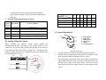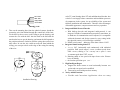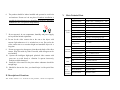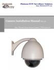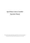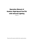
1
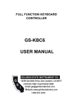
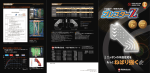
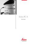
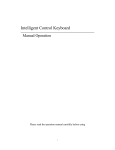
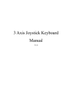
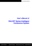
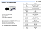
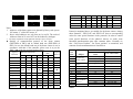
ON
ON
1
2
3
4
5
6 7
8
9 10
Speed Dome Addr ess=1
ON
ON
1
2
3
4
5
6 7
8
9 10
1
Speed Dome Addr ess=2
1
2
3
4
5
6 7
8
9 10
3
4
5
6 7
8
9 10
Speed Dome Addr ess=3
ON
Speed Dome Addr ess=4
2
ON
1
2
3
4
5
6 7
8
9 10
1
Speed Dome Addr ess=18
2
3
4
5
6 7
8
9 10
Speed Dome Addr ess=1023
Notes:
1. Addresses of the dome cameras are denoted by binary code system.
ON means “1” while OFF means “0”.
2. Above coded addresses are only from no.1 to no.20. The codes of
addresses from no.21 to no.1023 can be deduced by analogue.
3.
The range of addresses of the spherical cameras is from 1 to 1023.
z
Settings of communication protocol of the dome camera
(DIP1-DIP4 of SW2) and its default baud rate (DIP5-DIP6 of
SW2). In case the default baud rate of the dome camera is not in
accordance with that of the controller, please reset it as per the
Table 3 (● means the protocol has been done).
1st
2nd
3rd
4th
Normal Baud
Integrated
Rate
Protocol
5th
6th
A01
OFF
OFF
OFF
OFF
ON
OFF
●
B01
ON
OFF
OFF
OFF
OFF
ON
●
Santachi
OFF
ON
OFF
OFF
OFF
ON
●
PELCO-D
ON
ON
OFF
OFF
OFF
OFF
●
ON
OFF
OFF
ON
Type of
Protocols
PELCO-P/4800
Selection of Protocols
●
OFF
OFF
ON
OFF
PANASONIC
ON
OFF
ON
OFF
OFF
ON
○
Longcomity
OFF
ON
ON
OFF
OFF
ON
●
HUNDA600
ON
ON
ON
OFF
OFF
ON
●
LILIN
OFF
OFF
OFF
ON
ON
OFF
○
VICON
ON
OFF
OFF
ON
ON
OFF
○
MOLYNX
OFF
ON
OFF
ON
OFF
ON
○
PELCO-P/9600
KALATEL
ON
ON
OFF
ON
VCL
OFF
OFF
ON
ON
DAIWA
ON
OFF
ON
ON
ALEC
OFF
ON
ON
ON
Utralk
ON
ON
ON
ON
OFF
○
OFF
ON
○
OFF
ON
○
OFF
ON
○
OFF
ON
○
ON
Table 2
Protocols mentioned above are suitable for the dome camera. Among
them “Santachi”, “PELCO-D” and “PELCO-P” have no corresponding
orders for some special functions in the protocols. In order to control
some special functions of the spherical camera, we make some
functional transformation upon some common orders. Normally we
take “Call Preset Position / Set Preset position” to transform, and
contents of order transformation are listed below.
Number
of N
Value
51
52
53
54
55
56
57
58
59
60
61
62
63
64
Notes:
Control
Object
Supplementary
Control of dome
Power Supply of
Camera
BLC
Zero Illuminance
Screen Display *
D-Zoom
Focus
Iris
Mode of White
Balance *
Definition of Keypad Operation
Call No. N Preset
Point
Start Scan (low Speed)
Start Scan (middle Speed)
Start Scan (high Speed)
Start Patrol
Set Start Position of Scan
Set End Position of Scan
Power Supply On
Power Supply Off
On
On
On
On
Automatic
Automatic
Automatic
Interior
ATW
Set No. N Preset Point
Off
Off
Off
Off
Manual
Manual
Manual
Exterior
One Push WB
1. Those Items with “*” have memory function even the dome is
switched off.
2. For those cameras with “menu”, you can use “Screen Display ON”
to control the Menu ON/OFF, and use “Screen Display OFF” to
control Screen Display ON/OFF.
3. For those cameras which have no “Zero Illuminance” or the
function of “Zero Illuminance” is automatically switched without
control, and then above “Zero Illuminance” is invalid.
4. Notes to “Patrol” Function of the dome camera:
① Automatically scan from no.1 to no.16 preset points one by
one. If some points do not have been preset or are cleared out
after presetting, they will be bypassed when patrol is carrying
out.
② The dwelling time between to preset points is 4 seconds.
③ The “Patrol” function of the dome camera can be carried out
by presetting no.51 positions.
5. Notes to “Scan (auto pan)” Function of the dome camera:
① The dome camera makes automatic scan between two
specified positions.
② The speeds of scan are divided into three levels. You can call
no. 51, 52 and 53 preset positions to start scan at speed of
1.5°/ sec, 5°/ sec and 10°/ sec separately.
③ The dwelling time between the “Start Point” and “End Point”
of scan is 3 seconds.
6. All notes mentioned above are supplementary descriptions under
high speed. All original operations of the control system are
unchanged.
● Settings of Communication Baud Rate of the dome Camera
JP1 is jumper for the terminal resistor
JP1 is the 120 Ω terminal resistor for RS485 Bus. When short-circuit
terminal is set between “1-2”, the 120 Ω terminal resistor is opened
while it is set between “2-3”, the resistor is connected. Take care that on
RS 485 Bus only one farthest spherical camera has the terminal resistor
connected while other devices should have their terminal resistors
opened.
Settings of Addresses of dome Cameras
Dome
Address
1
2
3
4
5
6
7
8
9
10
11
12
13
14
15
16
17
18
…
1023
States of Coding Switches
1st
ON
OFF
ON
OFF
ON
OFF
ON
OFF
ON
OFF
ON
OFF
ON
OFF
ON
OFF
ON
OFF
…
ON
2nd
OFF
ON
ON
OFF
OFF
ON
ON
OFF
OFF
ON
ON
OFF
OFF
ON
ON
OFF
OFF
ON
…
ON
3rs
OFF
OFF
OFF
ON
ON
ON
ON
OFF
OFF
OFF
OFF
ON
ON
ON
ON
OFF
OFF
OFF
…
ON
4th
OFF
OFF
OFF
OFF
OFF
OFF
OFF
ON
ON
ON
ON
ON
ON
ON
ON
OFF
OFF
OFF
…
ON
5th
OFF
OFF
OFF
OFF
OFF
OFF
OFF
OFF
OFF
OFF
OFF
OFF
OFF
OFF
OFF
ON
ON
ON
…
ON
6th
OFF
OFF
OFF
OFF
OFF
OFF
OFF
OFF
OFF
OFF
OFF
OFF
OFF
OFF
OFF
OFF
OFF
OFF
…
ON
Table 1
For Example:
7th
OFF
OFF
OFF
OFF
OFF
OFF
OFF
OFF
OFF
OFF
OFF
OFF
OFF
OFF
OFF
OFF
OFF
OFF
…
ON
8th
OFF
OFF
OFF
OFF
OFF
OFF
OFF
OFF
OFF
OFF
OFF
OFF
OFF
OFF
OFF
OFF
OFF
OFF
…
ON
9th
OFF
OFF
OFF
OFF
OFF
OFF
OFF
OFF
OFF
OFF
OFF
OFF
OFF
OFF
OFF
OFF
OFF
OFF
…
ON
10th
OFF
OFF
OFF
OFF
OFF
OFF
OFF
OFF
OFF
OFF
OFF
OFF
OFF
OFF
OFF
OFF
OFF
OFF
…
ON
communication protocols integrated inside the spherical
camera and the baud rates can be selected from 24000 bps to
19200 bps.
5. Selectable Optical Zoom Range of Camera
Times of
Optical
Zooming
16x
18x
Focus Range
Lowest Luminance
f3.9-f6.3 mm
f4.1-f73.8 mm
1 Lux (F1.4)
1 Lux (common type) / 0.01 Lux(day & night type)
22x
f4-f88 mm
0.2 Lux(F1.6 1/3s)
23x
f3.6-f82.8 mm
1 Lux (Common type) / 0.01 Lux(day & night type)
25x
f3.6-f90 mm
1 Lux (Common type) / 0.01 Lux(day & night type)
III. Settings of Special Camera
Before installing the spherical camera, please confirm the
communication protocol and baud rate the master controler in the
system uses, then set the coding switches on the back of the camera to
be identical with that of the system in which SW1 is for address of the
spherical camera and SW2 is for communication protocol and baud rate
(see attached tables 1,2 and 3).
SW1
SW2
ON
ON
1
2
3
4
5
6
Pr ot ocol Sel ect
1
2
3
4
5
6 7
8
9 10
Speed Dome Addr ess Sel ect
1 2 3
JP
120Ω terminal resistor is opened for RS485 bus
1 2 3
JP
120Ω terminal resistor is connected on RS485 Bus
I D- CODE Set
Syst em
cont r ol wi r e
Coding Switch
Baud Rate
1
2
3
4
5
6
2400 bps
OFF
OFF
4800 bps
ON
OFF
9600 bps
OFF
ON
19200 bps
ON
ON
IV. Steps of Installation
1. M ounting Base
2.
3.
4.
5.
6.
Outer Tube
Shading Cover
Outer Cover
Camera
Connecting Cable
Dimension Drawing
1. Carefully read the operation manual and the points for attention.
2. Carefully set the communication code, baud rate and address of the
dome camera and make confirmation they are correct.
3. Take out the plug of the dome camera and connect external power
supply, RS485 and video wires as per marks on the plug. Take care
that the power supply of the dome camera is DC12V/1.2A and
adopt the particular power supply which is provided with the dome
camera.
color TV, omni bearing dome P/T and multifunctional decoder into
a whole. It can largely reduce connection and installation processes
of components in the system, rise up reliability of the system and
facilitate installation and maintenance. Therefore it has advantages
of beautiful appearance, compact structure and easy operation.
Red : DC12V+
Black : GND
Orange : RS485+
Yellow: RS485VIDEO
.
4.
Take out the mounting base from the spherical camera; thread the
connecting wire from behind through the central hole of the base.
Fix the base by three screws on the ceiling as per the drawing, and
connect the wire with the ball. Aim the latch in the ball with the
notch on the base as per the drawing, and mount the ball upward to
the position and turn it clockwise until the spring sheet on the base
takes effect. In case the wire could not come out from behind the
ceiling, you can open a hole on the edge of the casing for running
of the wire.
1. Integrated Multi-Protocol Decoder
a. With built-up decoder and integrated multi-protocol, it can
integrate 16 kinds of communication protocols in maximum. As
its baud rate of communication can be adjusted, it is compatible
with main domestic and foreign systems by easy setting inside
the spherical camera, so it has stronger versatility.
b. RS485 serial control: addresses of the dome camera 1-1023.
2. Integrated Omni bearing dome P/T
a. Turning 360º horizontally and continuously with unlimited
positions. PAN speed range:0~15rad/s (constant speed dome
PAN: 15rad/s); turning 0~90º vertically with a speed 0 ~15rad
/s(constant speed dome TILT: 15rad/s).
b. Running stably at low speed with super lower noise. Pictures
have no shaking.
c. the location precision up to ±0.2°.
3. High Intelligent Degree
a.
Support the dome camera to scan horizontally between two
points and scan speed can be modified.
b. Data can be stored with powerless memory.
4. Newly-Added Functions
a. Flexible and Convenient Application: there are many
Installation Drawing
6. The product should be indoor installed and operated to avoid rain
V. Main Technical Data
and moisture. Do not use it in wet places. If outdoor installation is
needed, the closed protect cover should be used and it is absolutely
prohibited to use it in open air independently.
Specifica
-tions
Image Inductor
1/4″Color CCD
Effective Pixels
752H×582V(440000pixels) PAL
Synchronous System
Internal Synchronization
VF Output
Compound Signal 1.0Vp-p/75Ω
White Balance
Automatic/Manual
Power Supply
DC12V±10%
1.2A
Power Consumption
12VA
7. Do not operate it in case temperature, humidity and power supply
are beyond the limited stipulations.
Weight
2Kg
Mounting Style
Ceiling or ceiling hanging style
8.Do not let the video camera aim at the sun or the object with
extreme light whatsoever it is switched on or not. Do not let the
video camera aim at or monitor bright and standstill object for a
long time.
9. Do not use aggressive detergent to clean the main body of the video
camera. Wipe dirt with dry cloth. If needed, mild detergent can be
used suitably.
10. Operate the intelligent high-speed spherical video camera with
great care to avoid shock or vibration. It operate incorrectly,
machine could be damaged.
11. Install the video camera in the place where endurance should be
enough large.
12. Should be dust on the lens, you should wipe it with special lens
tissue.
Relative humidity
10-75%(under no condensing)
Operation
Temperature
0℃~40℃
Scan System
15.625KHz(H) 50Hz (V)
Horizontal Resolution
480 TV lines
Signal / Noise ratio
Larger than 48 db
Electronic Shutter
1/3~1/10000 seconds
II. Description of Functions
The dome camera is a hi-tech CCTV product, which incorporates
Camera
Function
Lens
Data
Basic
Function
-s of
Spherica
l Camera
Lowest Temperature
1Lux,AGC ON
Zooming Range
18×Optical and 12×Digital
Iris
Automatic/Manual
Focus
Automatic/Manual
Horizontal Turning
0--15°/s (constant P/T: 15°/s fixed)
Vertical Turning
0--15°/s (constant P/T: 15°/s fixed)
Preset Positions
64 presets (max)
Patrol Function
At best 6 cruises
VI. Analysis of Normal Troubles
Problems
No action and
images when
power is switched
on
Abnormal
self-inspection.
Images with
roaring sound of
the motor
Normal
self-inspection
but no images
Successful
self-inspection
but out of control
Possible Causes
Power supply damaged or
insufficient power
Wrong connection of power
supply
Faults in engineering circuits
Mechanical fault
Tilting camera
Insufficient electrical power
Wrong connection of VF circuit
Bad connection of VF circuit
Camera damaged
Wrong connection of control
signal wire
Mismatched address of spherical
camera
Mismatched protocol
Images unstable
Dome Camera out
of control
I.
Bad connection of VF circuit
Insufficient electrical power
Abnormal self-inspection
Bad connection of control wire
Problems on main frame
Too heavy load or longer
distance of communication
Remedies
Replace
Correct
Remove
Repair
Place uprightly
Replace with qualified power
supply and let it close to the
spherical camera
Correct
Remove
Replace
Correct
Reselect
Adjust protocol to match with
the controller and switch on
again
Remove
Replace
Switch on again
Remove
Switch on the main frame
1. Connect 120Ω resistor
to the farthest camera and let
other cameras to be broken;
2. Increase code distributor.
Points for Attention
1. Before installing the omni bearing intelligent unit, please read the
operation manual carefully.
2. The camera takes power supply of DC12V/1.2A. You should assure
that the power supply of the product has an input voltage with load
about 12V rather than a unload voltage of 12V, otherwise the
camera couldn’t work normally.
3. During the process of transportation, storage and installation, the
dome should be avoided of incorrect operations such as heavy
pressing, strong vibration etc. which can cause damage of product
as there are sophisticated optical and electronic devices inside the
machine.
4. Do not attempt to disassemble the camera. In order to prevent
electric shock, do not remove screws or covers. There are no user
serviceable parts inside and only qualified personnel are to service
the unit
5.
Always follow all electrical standards for safety when it is in operation.
Adopt the particular power supply, which is provided with the dome. RS-485
and video signal should keep enough distance with high voltage equipments
and cables when they are in transmission. Precautions for anti-lightning and
anti-surging should be taken if necessary.
Normal problems and their causes and remedies mentioned above
are only for reference. Should you meet other special problems, you
can ask for technical support from your dealer directly.
SIX-INCHES DOME P/T
Please read the operation manual carefully before installing and
using this unit