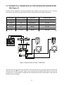
1
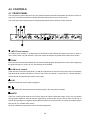
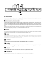
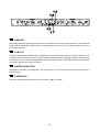
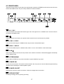
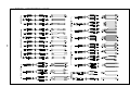
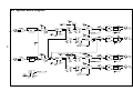
PHONIC PCR2213 USER MANUAL IMPORTANT SAFETY INSTRUCTIONS The apparatus shall not be exposed to dripping or splashing and that no objects with liquids, such as vases, shall be placed on the apparatus. The MAINS plug is used as the disconnect device, the disconnect device shall remain readily operable. Warning: the user shall not place this apparatus in the can be easily accessible. area during the operation so that the mains switch 1. Read these instructions before operating this apparatus. CAUTION 2. Keep these instructions for future reference. RISK OF ELECTRIC SHOCK DO NOT OPEN 3. Heed all warnings to ensure safe operation. 4. Follow all instructions provided in this document. 5. Do not use this apparatus near water or in locations where condensation may occur. 6. Clean only with dry cloth. Do not use aerosol or liquid cleaners. Unplug this apparatus before cleaning. 7. Do not block any of the ventilation openings. Install in accordance with the manufacturer’s instructions. 8. Do not install near any heat sources such as radiators, heat registers, stoves, or other apparatus (including . 9. Do not defeat the safety purpose of the polarized or grounding-type plug. A polarized plug has two blades with one wider than the other. A grounding type plug has two blades and a third grounding prong. The wide blade or the third prong is provided for your safety. If the provided plug does not into your outlet, consult an electrician for replacement of the obsolete outlet. 10. Protect the power cord from being walked on or pinched particularly at plug, convenience receptacles, and the point where they exit from the apparatus. 11. Only use attachments/accessories manufacturer. by the 12. Use only with a cart, stand, tripod, bracket, or table by the manufacturer, or sold with the apparatus. When a cart is used, use caution when moving the cart/apparatus combination to avoid injury from tipover. 13. Unplug this apparatus during lighting storms or when unused for long periods of time. 14. Refer all servicing to service personnel. Servicing is required when the apparatus has been damaged in any way, such as power-supply cord or plug is damaged, liquid has been spilled or objects have fallen into the apparatus, the apparatus has been exposed to rain or moisture, does not operate normally, or has been dropped. CAUTION: TO REDUCE THE RISK OF ELECTRIC SHOCK, DO NOT REMOVE COVER (OR BACK) NO USER SERVICEABLE PARTS INSIDE REFER SERVICING TO QUALIFIED PERSONNEL The lightning flash with arrowhead symbol, within an equilateral triangle, is intended to alert the user to the presence of uninsulated “dangerous voltage” within the product’ magnitude to constitute a risk of electric shock to persons. The exclamation point within an equilateral triangle is intended to alert the user to the presence of important operating and maintenance (servicing) instructions in the literature accompanying the appliance. WARNING: To reduce the risk of or electric shock, do not expose this apparatus to rain or moisture. CAUTION: Use of controls or adjustments or performance of procedures other than those may result in hazardous radiation exposure. CONTENTS 1.0 PREFACE ................................................................................................ 4 1.1 MULTIPLE-WAY SPEAKER SYSTEMS .............................................................. 4 1.2 PCR2213 THE ULTIMATE CROSSOVER FOR ADVANCED SPEAKER ........... 4 2.0 DESIGN YOUR SPEAKER SYSTEM WITH PCR2213 ........................... 6 2.1 2-WAY SYSTEM .................................................................................................. 6 2.2 3-WAY SYSTEM .................................................................................................. 7 2.3 PASSIVE FULL RANGE WITH ACTIVE-CROSSOVER SUB-WOOFER ........... 8 2.4 STEREO ACTIVE 2-WAY WITH SUB-WOOFER ................................................ 9 2.5 STEREO ACTIVE 3-WAY WITH SUB-WOOFER .............................................. 10 2.6 4-WAY, 5-WAY ................................................................................................... 10 3.0 INSTALLATION...................................................................................... 11 3.1 RACK MOUNTING ............................................................................................ 11 3.2 CONNECTORS ................................................................................................. 11 3.2.1 IMPEDANCE ................................................................................................................... 11 3.2.2 UNBALANCED/BALANCED CONNECTION ................................................................. 11 3.2.3 THE CORRECT WIRING FOR BALANCED OPERATION ............................................. 12 3.2.4 UNBALANCED OPERATION ......................................................................................... 12 3.2.5 BALANCED OPERATION .............................................................................................. 12 3.3 MAINS CONNECTION ...................................................................................... 13 3.3.1 SAFETY FUSE REPLACEMENT ................................................................................... 13 4.0 CONTROLS ........................................................................................... 14 4.1 FRONT PANEL .................................................................................................. 14 4.2 REAR PANEL .................................................................................................... 17 2 5.0 HOW TO SET UP A MULTI-WAY SPEAKER SYSTEM ........................ 18 5.1 EQUIPMENT AND INSTRUMENTS .................................................................. 18 5.1.1 MEASUREMENT MICROPHONE (CALIBRATED AND MATCHED WITH RTA OR ETF/TEF) ........................................... 18 5.1.2 REAL TIME ANALYZER (RTA), ENERGY-TIME-FREQUENCY (ETF OR TEF), FFT, OR MLSSA INCLUDING A SOUND PRESSURE LEVEL METER ................................. 18 5.1.3 FUNCTION GENERATOR WITH FREQUENCY DISPLAY ............................................ 18 5.1.4 AC VOLTMETER ........................................................................................................... 18 5.1.5 YOUR FAMILIAR CDS.................................................................................................... 18 5.2 2-WAY SYSTEM LEVEL SETTING ................................................................... 19 5.3 3-WAY SYSTEM LEVEL SETTING ................................................................... 20 5.4 DELAY TIME ..................................................................................................... 21 5.5 LIMITER SETTING ............................................................................................ 21 5.6 SUB ............................................................................................................... 22 5.7 HORN EQ .......................................................................................................... 22 6.0 TYPICAL CONNECTING LEADS .......................................................... 23 7.0 SPECIFICATIONS ................................................................................. 24 8.0 SYSTEM BLOCK DIAGRAM ................................................................. 25 9.0 REFERENCE BOOKS ........................................................................... 26 3 1.0 PREFACE In most of the professional audio applications, multiple speakers are employed for covering the whole audience area as well as frequency band. When sound waves are generated with multiple speakers, proper arrangement is a standard and recommended practice by audio design engineers and installation technicians. Phonic provides this active crossover as part of the speaker system, which work together with speaker drivers, highs or lows, and amplifiers, big or small. This crossover will be successful if you carefully design and align the whole speaker system according to the following explanation and recommended practice. 1.1 MULTIPLE-WAY SPEAKER SYSTEMS Full bandwidth covering 20Hz to 20KHz as human audible band, no single speaker driver can cover this range with wave length differ by 1000 times with good quality and sufficient sound pressure level. To deal with this limit, audio engineers need to use multiple speaker drivers for different frequency band, and we call these designs as multiple-way system. Multiple-way means different speakers covering different frequency band, and multiple speakers could be in the same band. For professional applications, 2-way and 3-way designs are most popular configuration. To build a 2-way or 3way speaker system, crossover network is needed to divide the frequency band into high and low (or high, mid, low) section. Crossover can be passive or active. Passive crossover can be found in smaller speaker system that is assembled with inductors, capacitors, and resistors. Amplifier send in the signal to the passive crossover network and then to the high and low frequency speakers accordingly. Active crossover did this differently, it is positioned before the power amplifiers. Then, the power amplifier send the signal directly to the high or low frequency speakers directly without the passive crossover inserted. The benefit are: ! More solid bass for lower resistance between speaker and amplifier that maintain effective damping factor. ! Lower inter-modulation distortion (IMD). ! Save the insertion loss, normally in the range of 1 to 3 dB. That means save the lost from 20% to 50%. ! Increase power efficiency for less composite signal that will demand lower voltage swing of power amplifiers, and still provide the same sound pressure level. ! Save the high frequency drivers from damage by large low frequency signal clipping the power amplifiers which generate high level harmonic signal. This is the phenomenon that underpower amplifier will burn tweeter when clipping. If the user doesnt follow the exact procedure to set-up the speaker system with active crossover, the result is always very bad and worst than passive crossover speakers. Because the passive crossover was already properly adjusted by the designer and maker. OK, lets see how we can get the best of the system performance with Phonic PCR2213. 1.2 PCR2213 THE ULTIMATE CROSSOVER FOR ADVANCED SPEAKER SYSTEM The PCR2213 is a very high quality active crossover. It is designed with 2, 3 or more way speaker systems in mind with 1, 2 or more PCR2213 to achieve it. The PCR2213 may be used with large sound systems in auditoriums, theaters, pubs, amusement parks, or touring concerts. Also for high quality bi-amp stage monitors, or adding a mono sub-woofer for studio monitors in a control room. The Phonic PCR2213 is a high precision tool with a lot of advanced features: ! Stereo 2-way or mono 3-way operation. ! Reasonable ways speaker system with multiple PCR2213. ! Industrial standard state variable 24 dB/octave Linkwitz-Riley filters with zero phase error at crossover 4 ! ! ! ! ! ! ! ! ! ! frequencies. Perfect flat summed amplitude response at all Crossover frequencies. Independent limiters on all outputs with pre-defined time parameters. Latching mute push buttons on all outputs. It is a vital function during setting up and troubleshooting. LED indication on all important switching functions for easy status identification. Crossover frequencies continuously variable from 80 - 8000 Hz Time/phase alignment via polarity switches and 4 msec time delay controls Switchable horn EQ curve to compensate the HF roll-off. RF and Subsonic input filters. High precision components and potentiometers ensure excellent quality and accuracy of settings Servo-balanced XLR inputs and outputs 5 2.0 DESIGN YOUR SPEAKER SYSTEM WITH PCR2213 When designing the speaker system, first determine the frequency bandwidth you want to cover and the maximum sound pressure level you want to achieve. Select those components that meet your demand. Carefully note the frequency range each driver covered. Following are some most popular configuration, PCR2213 is not limited within the listed application. Multiple PCR2213 can form even more than 10-way speaker system, although it is not practical. The recommended crossover points are listed for your reference, your components will fall in the recommended range mostly, but exception exists! 2.1 2-WAY SYSTEM (Ref:Figure 1) PCR2213 is capable of dual 2-way system in stereo mode. The crossover frequency can be anywhere between 80 to 8000Hz. Most 2-way system crossover between 500 to 5000Hz. Following are the table of popular 2-way configuration and recommended crossover frequency: Bass Unit HF Unit Application Lowest Point Highest Point 15" 1"~2" HF Horn Stage 500 200 0 12" 1"~2" HF Horn Stage 800 250 0 10" 1"~2" Dome Monitor 1200 500 0 8" 1"~2" Dome Monitor 1500 500 0 Figure 1:Typical Active 2-way System 6 2.2 3-WAY SYSTEM (Ref:Figure 2) PCR2213 is capable of single 3-way speaker system with one unit. The low/mid and mid/high crossover frequency can be set between 80 to 8000Hz. Most 3-way system have low/mid crossover point at 200~2000Hz, and mid/high at 800~8000Hz. Following are the table of popular 3-way configuration and recommended crossover frequency: Bass Mid High Application Low/Mid Mid/High 18" 10" 1"~2" Horn Stage 200~500 2000~5000 15" 6.5~10" 1"~2" Horn Stage/Monitor 200~800 2000~5000 12" 4~6.5" 1"~2" Dome Monitor 300~1000 3000~8000 10 " 3~6.5" 1"~2" Dome Monitor 500~1000 3000~8000 Figure 2:Typical Active 3-way System 7 2.3 PASSIVE FULL RANGE WITH ACTIVE-CROSSOVER SUB-WOOFER (Ref:Figure 3) PCR 2213 is very suitable for sub-woofer application and is capable of this system with one unit. The crossover frequency is always low at 80~200Hz. Following a table to list some popular configuration: Sub woofer Bass of full range Application Crossover Point 18 " 15" Stage/Monitor 80~100 15"~18" 12" Stage/Monitor 80~120 15"~18" 10" Stage/Monitor 80~150 15" 8" Monitor 80~120 12"~15" 8" Monitor 80~150 10"~12" 6.5"~8" Monitor 100~150 8"~10" 5"~6.5" Monitor 100~180 Figure 3:Typical Passive 2-way + Subwoofer PCR 2213 has a sub- switch in the rear panel. This switch will sum the low frequency part of both channels and send it out from both low outputs. When you are using this type of speaker system with one or more subwoofer boxes, it is recommended to engage the switch and put all the woofer boxes together in the center line between the stereo speakers. 8 2.4 STEREO ACTIVE 2-WAY WITH SUB-WOOFER (Ref:Figure 4) Some people will regard this as 3-way, and it really is. There are 2 configuration you can achieve:(1)Treat it as 3-way and do it as the same as 2.2. (2)Treat it as 2-way plus sub-woofer as the same as 2.1 + 2.3. The later configuration benefit the summed sub-woofer output from both channels, and thus better than pure 3way configuration. No matter which configuration, you need two PCR2213 for this system. Figure 4:Typical Active 2-way + Subwoofer 9 2.5 STEREO ACTIVE 3-WAY WITH SUB-WOOFER Some people will regard this as 4-way. But most 4-way system is actually 3-way plus sub-woofer. There are 2 configuration you can achieve: (1)Treat it as 4-way and put two PCR 2213 in each channel, you will need four PCR 2213. (2)Treat it as 3-way plus sub-woofer as the same as 2.2 + 2.3, and you are using three PCR 2213 for the whole system. The later configuration benefit the summed sub-woofer output with both channel, and saves you one PCR 2213. Although we appreciate if you would like to buy more unit, but technically we dont suggest this configuration. 2.6 4-WAY, 5-WAY ...... You can always achieve multiple ways system with multiple PCR2213, always send the next PCR2213 with low frequency output for easiest time alignment. Following the table for various ways configuration: Stereo 4-way 3 x PCR2213 Stereo 5-way 4 x PCR2213 Stereo 6-way 5 x PCR2213 Stereo 7-way 6 x PCR2213 10 3.0 INSTALLATION 3.1 RACK MOUNTING The Phonic PCR2213 fits into standard rack, and takes one unit height of space (1 3/4"). Additional 4" depth for the connectors on the back panel is needed. Be sure that there is enough air space around the unit for cooling and please do not place the PCR2213 in contact to or directly on top of high temperature devices such as power amplifiers etc. to avoid overheating. 3.2 CONNECTORS The PCR2213 has to be connected with XLR plugs. Although the inputs and outputs are fully balanced, the active servo circuitry can be wired with unbalanced sources and loads as well. 3.2.1 Impedance Both of the inputs impedance are 20k Ohms and can be driven by most sources. If a device's output requires a match load of 600 Ohms (mostly from output transformers), 600 Ohms resistor should be tied across pin 2 and 3 on the input connectors. As standard, the outputs of the PCR2213 are electronically balanced and have an output impedance lower than 100 Ohms. When driving transformer coupled loads, it may be necessary to create a 600-Ohm source impedance. For this purpose, install two 247 Ohms resistors in series with pin 2 and 3. 3.2.2 Unbalanced/Balanced Connection Most of the mistakes in audio installations are incorrect and defective audio connections. In order to perfectly complete your installation, please pay special attention to the following section unless you are already familiar with balanced/unbalanced operation. ! What is an unbalanced system? You can find this system in most of home audio-video system. It got one conductor to carry the signal, and the other conductor for ground. Normally for lower level signal, the signal conductor is shielded by the ground conductor. ! What is a balanced system? Balanced system transmits the signal via 2 conductors plus one ground shielding conductor. The 2 signal conductors carry the same signal but out of phase. For the balanced input stage, the amplifier will boost the difference of the 2 signal conductors and remove the identical part (known as common mode signal.) of the 2 signal conductors. Because of the real signal is carried by the 2 conductors out of phase, so it is perfectly carry to the input. At the same time, the interference occurs during transmission will be identical part (common mode), because the signal conductors are run together, there is no chance they can be different, and all the interference will be removed by the balanced input amplifier. 11 ! The difference in between 2 operations: Because the common mode interference immunity of balanced system, and at the same time, the ground conductor doesnt need to carry any electrical current so that it means the ground of the 2 connected units has identical ground level which is vital to interference free system. Lets look back to unbalanced system, the signal electrical current is from signal conductor to ground conductor, and that means the ground level of 2 connected units are not identical. This means the system is much more easier to be interfered with noise. Running long cables is easy for balanced system but difficult for unbalanced system, and lower noise isalways characterized in balanced system. Because balanced system needs 2 conductors for signal and 1 conductor for ground, minimum 3 conductors are needed for wiring balanced system. So dedicated system separates ground and shield as 2 conductors. Please read following section for proper wiring balanced and unbalanced system: 3.2.3 The Correct Wiring for Balanced Operation Always connect the main power with 3-prong plug. Make sure the power system ground is properly done. Dont use ground insulator plug adapter without properly connect the ground individually. This is vital to a successful audio system connection. Always connect the ground pin (PIN 1 in XLR) to the source unit, and disconnect this pin at the destination unit. This connection topology is to avoid grounding loop created by both connection of signal and power ground. To utilize only the power ground, is because it always has lower resistance and better distribution than signal ground. If there is hum, a very possible cause is bad grounding connection in the system. In case you can not find the cause, try to connect the ground pin of the input connectors. If the hum is reduced or eliminated, check your power grounding system. Special attention while distant equipment racks, and/or large quantity of power amplifiers are used. Check the power ground between the racks and power distribution strips with your electricity engineer. Do make sure there is one and only one proper ground point in the audio system (or connected video system.) 3.2.4 Unbalanced Operation PCR2213 is equipped with electronically balanced inputs and outputs which also function unbalanced inputs and outputs. The cross-feedback circuitry recognizes the connection of unbalanced loads and compensates 6 dB level difference when one of the signal is shorted to the ground.For connecting with unbalanced source to the input of PCR2213, connect PIN 2 of XLR connector to the source signal and the PIN 1 and 3 of XLR connector of PCR2213 to the source ground. For connected with unbalanced load to PCR2213, there are 2 possible wiring methods: (1): Connect PIN 2 of XLR connector to the load input, and connect PIN 1 of XLR connector to the load ground. (2): Connect PIN 2 of XLR connector to the load input, and connect PIN 1 and 3 of XLR connector to the load ground. 3.2.5 Balanced Operation The electrically balanced connections have the benefit of Common Mode Rejection which eliminates externally induced interference, such as mains hum etc. Balancing is especially useful when long cable runs are used between pieces of equipment. For connecting with balanced source to the input of PCR 2213, connect PIN 2 of XLR connector to the source 12 signal Hot(+), the PIN 3 to the source signal Cold(-) and the PIN 1 to the source Ground. 3.3 MAINS CONNECTION The mains connection of the PCR2213 is made by using a standard IEC receptacle and an universal mains cable. It meets all the requirements of the international safety certification. Make sure all the units in the sound system are properly grounded with good connection. For your own safety, do not to remove the ground connection within the units or at the supply, or fail to make this connection at all. The audio ground of the PCR2213 is capacitor de-coupled and isolate it from the power ground. Do not attempt to solve ground loop problem by disconnecting the power ground. 3.3.1 Safety Fuse Replacement A safety fuse protects the unit from serious malfunction. The fuse will blows in case of power problem or loading short circuits. After removing. the cause, and the identical specification fuse blows right after a new one replaced, there must be something wrong in the unit. NEVER use fuses higher or lower ratings fuses or other metal material. This can cause fire and electric shocks and will threaten your life and the lives of others. 13 4.0 CONTROLS 4.1 FRONT PANEL The front panel is printed with dual color, the yellow line above the knobs represents the function in stereo 2way mode. The white line below the knobs represents the function in mono 3-way mode. The center part with white background represents general functions effective to both channels. 1. INPUT level control: Two INPUT level controls (+/-12 dB) match the sensitivity of the PCR2213's inputs to any source. When in mono 3-way mode, only the channel 1 input level control is effective as printed at the bottom of the knobs. 2. PEAK Each input has an associated PEAK LED to indicate peaking signal. Bring down the level control supposing the peak led stays on. Keep it at very rare flashing at all possible. 3. LOW level control: These 2 knobs control the output level (+/-6 dB) of LOW portion for the user to set proper level in association with HIGH level controls [10]. When in mono 3-way mode, the channel 1 LOW is the LF, and the channel 2 LOW is the MF as printed at the bottom of the knobs. 4. LIM This led indicate the output limiter is triggered. 5. This led indicate the associate phase invert button [20] on the rear panel is pressed. 6. MUTE: There are 4 muting push switches next to the 4 outputs to mute the associate output. This is very convenient during system alignment. Always start the alignment by muting all the outputs, and un-mute the HF first. In case of wrong wiring the LF signal to HF amplifiers and drivers, this practice lets you notice the mistake without blow out all your valuable horn drivers. All these 4 switches incorporate a LED to indicate engagement. 14 7. DELAY control These 2 knobs adjust the signal delay of LF portion. The delay time is between 0~4msec, equal to 120cm to compensate the offset between HF horn and LF driver. 8. CROSSOVER 1, CROSSOVER 2 These are the precision crossover frequency control knobs to set the crossover points. The crossover frequency not only depends on this pot but also the range push switch [9] next to the pot. There are 2 range, x1 and x10. The x1 range is printed with white number, and the x10 range is printed with black number on white box. When in mono 3-way mode, the crossover 1 set the crossover frequency of low/mid, and the crossover 2 set the crossover frequency of mid/high as printed at the bottom of the knobs. 9. RANGE The crossover frequency range is cut into 2 for more precision control. 80 to 800Hz is the x1 range, and 800Hz to 8KHz is the x10 range. 2 LED are incorporated to show the selected range. 10. HIGH These 2 knobs control the output level (+/-6 dB) of HIGH portion for the user to set proper level in association with LOW level controls [3]. When in mono 3-way mode, the channel 1 HIGH is not used, and the channel 2 HIGH is the HF as printed at the bottom of the knob. 11. STEREO This led indicates the unit is in stereo mode. The mode is set by [24] in the rear panel. 12. SUB This led indicates the summing of the low portions of both channels. This mode is set by [23] in the rear panel. This mode will be disengaged in mono mode automatically. 13. MONO This led indicate the unit is in mono mode. The mode is set by [24] in the rear panel. 14. LIMITER ON This led indicates the limiters of the 4 outputs are on which is activated by button[17]. 15 15. HORN EQ Almost all professional high frequency horns have a tendency to roll off at very high frequency. This button will boost 12 dB at 15KHz with a gentle slope to compensate the roll-off. This is very useful to save the range on the graphic equalizer. 16. LOW CUT To protect vented bass speakers that is employed in most professional products, sub-sonic shall be cut to avoid excessive excursion. The low cut point is at 30Hz. Please do keep it engaged except you need the very low frequency. There is almost nothing below 30Hz in most music material. The programs that have those lows are movies, specially low frequency effects. 17. LIMITER ON BUTTON Although the 4 limiters are independent, the controls are not. This switch will activate or de-activate all 4 limiters at once. 18. THRESHOLD This knob set the threshold point of all 4 limiters from 6dBu to +18dBu. 16 4.2 REAR PANEL Just like the front panel, the text above the input/output sockets are STEREO mode and the text below the sockets are MONO mode. They are clearly marked to minimize mistakes. 19. IN 1 / IN 2 The input sockets are standard XLR female type. Set in the signal to IN 1 in MONO mode. The IN 2 socket is not effective in MONO mode. 20. These are phase invert buttons, the phase will be inverted as soon as the button is pressed. 21. LOW 1 / LOW 2 These are the LOW outputs. In MONO mode, they become LOW and MID output. 22. HIGH 1 / HIGH 2 These are the HIGH outputs. In MONO mode, HIGH 1 is not in used. HIGH 2 is the HIGH output. 23. SUB When set this switch to the left, the low portions of the 2 lows are summed. It will be disengaged automatically when in MONO mode. 24. STEREO/MONO Slide to left for STEREO 2-way mode, and slide to right for MONO 3-way mode. 25. POWER SW. To turn the unit on and off. This switch is best located in the rear panel to avoid accidental tampered during operation which endanger the whole speaker system. 26. POWER SOCKET Standard IEC socket for power connection. Check the voltage before connection. 27. GROUND POINT Chassis grounding point for properly grounding. 17 5.0 HOW TO SET UP A MULTI-WAY SPEAKER SYSTEM 5.1 EQUIPMENT AND INSTRUMENTS Properly prepare all necessary equipment and instruments before hand will help you fluently do the job, here are the list we suggested: 5.1.1 Measurement Microphone (Calibrated and matched with RTA or ETF/TEF) Alignment should be carried out with a good quality microphone, with a flat response at least from 50 Hz to about 16 kHz. Placed no less than 1 m (prefer at listening position, multiple measurements required for larger venue) in front of the speaker system being set-up, and at a vertical position between the drivers covering the two or more bands of the system. Only one speaker system at one time, never turn on multiple speaker system at the same time, you will never properly tune the system! 5.1.2 Real Time Analyzer (RTA), Energy-Time-Frequency (ETF or TEF), FFT, or MLSSA including a Sound Pressure Level Meter RTA is a popular device that shows the frequency response directly on the display. ETF or TEF, FFT, even MLSSA instruments dont show the frequency response directly, but after the instrument taking enough samples and finished the calculation. Precision measurement cannot be done by ordinary RTA, but it is a handy tool to do some quick job and in near field measurement. For more precision alignment, ETF/TEF or MLSSA is recommended. Please refer to the user guides of the instrument you are using for proper measurements. 5.1.3 Function Generator with frequency display This is a sine and square wave generator capable of variable frequency in the range of audio band. You need to have the frequency digital display or you need a external counter for the frequency reading purpose. This unit is needed to send out the precision frequency signal to the system. 5.1.4 AC voltmeter A good AC voltmeter (2 channel preferred) that reads in dB as well as volts is recommended for measuring the input and output level of each band. 5.1.5 Your familiar CDs Prepare some of your most familiar music CDs covering low to high frequency. Vocal singing and speaking shall be always included as this is most sensible to human ears. Experienced user put together frequent test reference sound tracks and standard signal such as pink/white noise into one CD or DAT for convenient trial listening. The instrument assist alignment will mean nothing without good listening experience. If you found problem while listening, dont try to adjust the system without instrument. In stead, you shall make use of the instrument to find out the problem, there must be something missing! 18 5.2 2-WAY SYSTEM LEVEL SETTING Properly setting level guarantee best performing system. Please follow the recommended procedure for best speaker system. 1. All system power off. 2. Connect the pink noise generator (on RTA or CD), the signal source required by the test instrument and variable frequency signal generator onto the main mixer. 3. Connect the measurement microphone to the instrument. 4. Make sure all the signal wiring is done properly setting on PCR2213 is done correctly. 5. Graphic equalizer at flat setting (or bypass). 6. Compressor/limiter at bypass setting. 7. All level control on power amplifiers at minimum. 8. Un-mute all output of PCR2213. 9. Turn on the system except power amplifiers. 10. Connect AC volt meter at the low output of the PCR2213 under test. 11. Make sure all mute switches and phase invert switches are not pressed. The limiter is off, subsonic filter is off and the horn EQ is not engaged. 12. Set the crossover point [8] as design, send in the sine wave from function generator at half of the crossover frequency. Adjust the channel fader and master fader to 0VU on the mixer. 13. Read the AC volt meter, it should be around 0dBu depending on the 0VU reference point of the mixer and the crossover point. 14. Change the frequency of the function generator to the crossover point. 15. Adjust the crossover frequency knob [8] slowly around the crossover frequency. Read the AC volt meter until it is 3dB lower than previous step. This is the exact position of the crossover point. Mark the position with a pencil. 16. Repeat the same procedure from step 10 to 14 with another channel crossover point. 17. Measure the axis distance between the bass speaker and high frequency driver (speaker), and calculate the approximate delay time to compensate the difference. Ref to 5.3 for detail. 18. Now, shut down all signal source. Make sure there is no output from the mixer by reading the level meter on the mixer. 19. Press down all the mute switches of PCR2213 except the HF output. 20. Turn on only the HF power amplifier with input level at minimum. 21. Send in the pink noise to the mixer, adjust the level until reaching 10dB. 22. Slowly turn up the level control of the HF power amplifier, make sure you are listening the HF sound clearly from the HF speakers. If you heard fussy HF sound from the bass speakers (It is hard to tell MF coming from MF or LF speakers), turn off the system and check system wiring thoroughly. It is highly possibly that the LF signal was send into HF speaker. If you turn on the LF first, HF speaker will be blown already. 23. OK, now the HF is correctly sent into HF speaker(s). Un-mute the LF output, and mute the HF output. 24. Slowly turn up the level control of the LF power amplifier, you should hear strong LF sound from the LF speakers. 25. Un-mute the HF, and turn up the level until the LF and HF is about balanced. 26. Turn up HF, MF and LF level until the sound pressure level reached 10dB below designed operating level. (If you set the operating at 90dB, you shall reach 80dB.) 27. Press down the low cut if youre using vented LF speaker which doesnt extend to 30Hz or lower. 28. Press down the Horn EQ if youre using HF horn which is constant directivity design. 29. Refer to 5.5 for limiter adjustment. 30. Fine tune the system with the steps instructed by the test instrument you are using. Please note the delay time can also be fine tuned with precision instrument such as ETF or TEF which include time domain 19 measurement. 5.3 3-WAY SYSTEM LEVEL SETTING Properly setting level guarantee best performing system. Please follow the recommended procedure for best speaker system. 1. 2. 3. 4. 5. 6. 7. 8. 9. 10. 11. 12. 13. 14. 15. 16. 17. 18. 19. 20. 21. 22. 23. 24. 25. 26. All system power off. Connect the pink noise generator (on RTA or CD), the signal source required by the test instrument and function generator onto the main mixer. Connect the measurement microphone to the instrument. Make sure all the signal wiring is done properly setting on PCR2213 is done correctly. Graphic equalizer at flat setting (or bypass). Compressor/limiter at bypass setting. All level control on power amplifiers at minimum. Un-mute all output of PCR2213. Turn on the system except power amplifiers. Connect AC voltmeter at the LF output of the PCR2213 under test. Make sure all mute switches and phase invert switches are not pressed. The limiter is off, subsonic filter is off and the horn EQ is not engaged. Set the LF/MF crossover point [8] as design, send in the sine wave from function generator at half of the crossover frequency. Adjust the channel fader and master fader to 0VU on the mixer. Read the AC voltmeter, it should be around 0dBu depending on the 0VU reference point of the mixer and the crossover point. Change the frequency of the function generator to the crossover point. Adjust the LF/MF crossover frequency knob [8] slowly around the crossover frequency. Read the AC voltmeter until it is 3dB lower than previous step. This is the exact position of the crossover point. Mark the position with a pencil. Connect the HF output to AC Voltmeter. Set the MF/HF crossover point [8] as design, send in the sine wave from function generator at 2X of the crossover frequency. Adjust the channel fader and master fader to 0VU on the mixer. Read the AC voltmeter, it should be around 0dBu depending on the 0VU reference point of the mixer. Change the frequency of the function generator to the crossover point. Adjust the MF/HF crossover frequency knob [8] slowly around the crossover frequency. Read the AC voltmeter until it is 3dB lower than previous step. This is the exact position of the crossover point. Mark the position with a pencil. Measure the axis distance between the MF speaker and high HF driver (speaker), and calculate the approximate delay time to compensate the difference. Ref to 5.3 for detail. Now, shut down all signal sources. Make sure there is no output from the mixer by reading the level meter on the mixer. Press down all the mute switches of PCR2213 excepts the HF output(s). Turn on only the HF power amplifier with input level at minimum. Send in the pink noise to the mixer, adjust the level until reaching 10dB. Slowly turn up the level control of the HF power amplifier, make sure you are listening the HF sound clearly from the HF speakers. If you heard fussy HF sound from the bass or mid speakers (It is hard to tell MF coming from MF or LF speakers), turn off the system and check system wiring thoroughly. It is highly possibly that the LF or MF signal was sent into HF speaker. If you turn on the LF first, HF speaker will be blown already. 20 27. OK, now the HF is correctly sent into HF speaker(s). Un-mute the MF output, and mute the HF output. Keep LF muted. 28. Turn on the MF power amplifier and slowly turn up the level control, you should hear MF sound from the MF speakers. 29. Press down all the mute switches of PCR2213 and release the LF mute switch. 30. Turn on the LF power amplifier with input level at minimum. 31. Slowly turn up the level control of the LF power amplifier, you should hear strong LF sound from the LF speakers. 32. Un-mute the HF and MF, and turn up the level until the LF, MF and HF are about balanced. 33. Turn up HF, MF and LF levels until the sound pressure level reached 10dB below designed operating level. (If you set the operating at 90dB, you shall reach 80dB. If you set the operating at 100dB, you shall reach 90dB, so on and so forth Our recommendation is 0VU at 90dB SPL for most of the application.) 34. Press down the low cut if youre using vented LF speaker which doesnt extend to 30Hz or lower. 35. Press down the Horn EQ if youre using HF horn which is constant directivity design. 36. Refer to 5.5 for limiter adjustment. 37. Fine tune the system with the steps instructed by the test instrument you are using. Please note the delay time can also be fine tuned with precision instrument such as ETF or TEF which include time domain measurement. *(Delay adjustment based on the HF diaphragm is the farthest, and MF is farther than LF. If this is not the case, and MF is the farthest, refer the LF delay time from MF, and HF may need additional time delay unit to compensate the offset.) 5.4 DELAY TIME The speed of sound is affected by air temperature. You can calculate the sound speed as following: C = 49 * (459.4 + °F)1/2 in feet per second. C = 20.6 * (273 + °C)1/2 in meter per second. Where C is the speed of sound. To compensate the offset between the speakers, the time will equal to the distance divided by speed. T = D/C Where T is the delay time in second, and D as distance in meter or feet between the speakers. The maximum delay time is 4 msec, which equal to 1.42 meters at 25°C or 4.52 feet at 72°F. This distance is sufficient for most speaker installation except those separating the speaker cabinet far apart. The very large long throw horns usually measure at 1.2 meters. If you have any huge horn to work with direct radiate bass unit, it is a good idea to move the bass a little back than the horn mouth. Keep the speaker driver distance within 1.4 meter will be fine for PCR2213. If you want to make a precise delay time adjustment, connect the PCR2213 with dual channel oscilloscope with PCR2213 input signal measured by one oscilloscope channel and LF output to the other channel. Send the sine wave into PCR2213 and adjust the delay time until the horizontal time offset equal to your design. 5.5 LIMITER SETTING 1. 2. To properly set the limiter threshold. You need to find out the capacity of the speaker and associated amplifier. Because the threshold is global setting, we shall make use of the level control on the PCR2213 as well as those on the power amplifiers, so that it works with all bands. Disconnect one set of the speakers and hook up dummy loads (same value as the speaker loading) to the amplifiers (You can connect only one output of the amplifier if you have multiple for the same band, and turn them off without removing the speaker connection. 21 3. 4. 5. 6. 7. 8. 9. 10. 11. 12. 13. 14. 15. 16. Turn the threshold all the way up, and switch on limiters. Lets start from the HF output. Turn up the mixer master level until the HF power channel reached the threshold power you want to limit. Turn down the threshold until the HF limiter indicator lighted. Now you have done the first limiter point. There are 3 more (or 2 more ) to go. If you keep all the output levels on PCR2213 at 0 (12 oclock), the LF output of the same channel probably reached limitng at the same time. But the power amplifier level maybe higher or lower than the power you wish to limit. If the limiting point is not yet reached, increase the mixer output level until the limiter indicator is lighted. If it was too high already, bring down the mixer output level until the limiter indicator just start to light. Mark the output level at this point by measuring with AC voltmeter. Turn up the level control of the power amplifier channel until it reached the level you wish to limit. Turn down the output level of PCR2213 until the power amplifier output level reduced back to the level marked in step 8. Now, this output limiter is done. Repeat the same procedure for other output limiter. After all limiter points are set, connect all the speaker loads back and send in the pink noise via the mixer again at 20dB (or 30dB) refer to previous level. Measure the HF amplifier channel used for previous setup and write down the value. Measure the other HF amplifier channels and adjust them as the same as the write down value. Measure the LF amplifier channel used for previous setup and write down the value. Measure the other LF amplifier channels and adjust them as the same as the write down value. 5.6 SUB In case the PCR2213 is used to work with sub-woofer system, no matter mono or stereo, it is good idea to drive all the sub-woofer boxes in the same phase with identical signal. Keep those sub-woofers the identical design with identical boxes and drivers at all possible. Slide the sub sigma switch will sum the 2 LF output of PCR2213 in stereo mode and send out the signal from both LF output jacks. This function will be automatically dis-engaged when the mode is set in MONO instead of STEREO. This practice is true no matter it is a big stage installation or small in studio monitoring. 5.7 HORN EQ 30 years ago, the horn designs could not reach constant dispersion over the frequency range it covers. The higher the frequency, the narrower the covering area. 20 years ago, the design of constant directivity can be realized, so that the energy can be distributed wider area especially in higher frequency. This expose a problem not noticeable in the past, because the high frequency energy output from the driver will drop gradually as the frequency goes higher. It was not a problem on axis before these constant directivity horns invented, and compensated with the beaming characteristic of older horn. But to take good care of the audience in various venues, constant directivity design provides much better performance between on axis versus off axis. To compensate this roll-off tendency, PCR2213 provides a HORN EQ switch which will boost +12dB at 15KHz with a 6dB/oct slope. This is a generic curve and work fine with most constant directivity horns, however fine tune may be needed with 1/3 octave equalizer. 22 6.0 TYPICAL CONNECTING LEADS 23 7.0 SPECIFICATIONS INPUTS Type Active Balanced Filter RF & switchable 30Hz HPF Gain Range -20~+4 dB Impedance >10Kohm, <100K ohm Frequency Response 10Hz ~ 100KHz, +0, -1dB Nominal operating level 0 dB u Maximum Input Level >+24dBu, balanced or unbalanced. Peak Indicator Red LED, at +18dBu CMRR >40dB OUTPUTS Type Active Balanced. Automatic correction for unbalanced loading. Output Impedance <100 ohm, balanced or unbalanced. Maximum Output level >+24dBu, balanced, +18dBu unbalanced. Frequency Response 10Hz ~ 100KHz, +0, -1dB THD @ +4dBu <0.005% IMD (SMPTE) @ +10dBu <0.01% Noise & Hum, 0dB Gain <-92dBu (20Hz to 20KHz, flat) Crossover @ 20KHz Better than -50dB Mute control On all outputs, with indicator. Phase invert On all outputs, with indicator. Sub Sigma Sum both stereo channel LF section and output at LF sockets, defeated in Mono mode. With indicator. FILTER Type Start variable 24dB/oct Linkwitz-Riley filter Mode Stereo 2-way or Mono 3-way, with indicators. Crossover Frequency 90~900Hz (x1) / 900~9000Hz (x10), range switching with tool. LF delay control 0~4 msec LF level control -12~+12dB HF level control -12~+12dB HF Horn EQ +12dB at 15KHz, 6dB/oct, +3dB @ 3.75KHz, with indicator. LIMITER Type Adjustable threshold limiter Threshold range Master variable control, -12~+12dBu Limiter on/off Master on/off control, with indicator. Indication On all outputs POWER SUPPLY & GND Mains voltage 100, 120, 220, 240 VAC, 50~60Hz. Power connection 3 pins, Hot, Neutral, & Ground. Fuse 1A (100~120VsAC), 1A (200~240VAC), slow blow. Chassis grounding Screw provided. Power consumption 10 W PHYSICAL Dimension 1.75" H, 19" W, 6.57" D Net Weight <3kg 24 8.0 System Block Diagram 25 9.0 Reference Books Phonic recommends the following books for those interested in advanced audio engineering and sound system operation: ! ! Sound System Engineering by Don and Carolyn Davis, Focal Press, ISBN: 0-240-80305-1 Sound Reinforcement Handbook by Gary D. Davis, Hal Leonard Publishing Corporation, ISBN: 0-88188900-8 ! ! ! ! Audio System Design and Installation by Philip Giddings, Focal Press, ISBN: 0-240-80286-1 Practical Recording Techniques by Bruce and Jenny Bartlett, Focal Press, ISBN: 0-240-80306-X Modern Recording Techniques by Huber & Runstein, Focal Press, ISBN: 0-240-80308-6 Sound Advice The Musicians Guide to the Recording Studio by Wayne Wadham, Schirmer Books, ISBN: 0-02-872694-4 ! Professional Microphone Techniques by David Mills Huber, Philip Williams. Hal Leonard Publishing Corporation, ISBN: 0-87288-685-9 ! Anatomy of a Home Studio : How Everything Really Works, from Microphones to Midi by Scott Wilkinson, Steve Oppenheimer, Mark Isham. Mix Books, ISBN: 091837121X ! Live Sound Reinforcement : A Comprehensive Guide to P.A. and Music Reinforcement Systems and Technology by Scott Hunter Stark. Mix Books, ISBN: 0918371074 ! Audiopro Home Recording Course Vol 1 : A Comprehensive Multimedia Audio Recording Text by Bill Gibson. Mix Books, ISBN: 0918371104 ! Audiopro Home Recording Course Vol 2 : A Comprehensive Multimedia Audio Recording Text by Bill Gibson. Mix Books, ISBN: 0918371201 26 6103 Johns Road #7