1
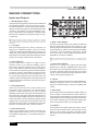
V1.5 2004/10/13
IMPORTANT SAFETY INSTRUCTIONS
1. Read these instructions before operating this
apparatus.
�������
2. Keep these instructions for future reference.
���� �� �������� �����
�� ��� ����
3. Heed all warnings to ensure safe operation.
4. Follow all instructions provided in this document.
5. Do not use this apparatus near water or in locations
where condensation may occur.
CAUTION: TO REDUCE THE RISK OF ELECTRIC SHOCK,
DO NOT REMOVE COVER (OR BACK)
NO USER SERVICEABLE PARTS INSIDE
REFER SERVICING TO QUALIFIED PERSONNEL
6. Clean only with dry cloth. Do not use aerosol or liquid
cleaners. Unplug this apparatus before cleaning.
The lightning flash with arrowhead symbol, within an equilateral triangle, is intended to alert the user to the presence
7. Do not block any of the ventilation openings. Install
in accordance with the manufacturer’s instructions.
of uninsulated “dangerous voltage” within the product’s
enclosure that may be of sufficient
8. Do not install near any heat sources such as radiators,
heat registers, stoves, or other apparatus (including
amplifiers) that produce heat.
9. Do not defeat the safety purpose of the polarized or
grounding-type plug. A polarized plug has two blades
with one wider than the other. A grounding type plug
has two blades and a third grounding prong. The wide
blade or the third prong is provided for your safety. If
the provided plug does not fit into your outlet, consult
an electrician for replacement of the obsolete outlet.
10. Protect the power cord from being walked on or
pinched particularly at plug, convenience receptacles,
and the point where they exit from the apparatus.
11. Only use attachments/accessories specified by the
manufacturer.
12. Use only with a cart, stand, tripod, bracket, or
table specifi ed by the manufacturer, or sold with
the apparatus. When a cart is used, use caution
when moving the cart/apparatus
combination to avoid injury from tipover.
13. Unplug this apparatus during lighting
storms or when unused for long
periods of time.
14. Refer all servicing to qualified service personnel.
Servicing is required when the apparatus has been
damaged in any way, such as power-supply cord or
plug is damaged, liquid has been spilled or objects
have fallen into the apparatus, the apparatus has
been exposed to rain or moisture, does not operate
normally, or has been dropped.
!
magnitude to constitute a risk of electric shock to persons.
!
The exclamation point within an equilateral triangle is intended to alert the user to the presence of important operating and maintenance (servicing) instructions in the literature
accompanying the appliance.
WARNING: To reduce the risk of fire or electric shock, do
not expose this apparatus to rain or moisture.
CAUTION: Use of controls or adjustments or performance
of procedures other than those specified may result in
hazardous radiation exposure.
MU200XP
Compact Powered Mixer
TABLE OF CONTENTS
page
INTRODUCTION ...................................................................................................... 4
FEATURES............................................................................................................... 4
CHANNEL SETUP ................................................................................................... 5
MAKING CONNECTIONS........................................................................................ 6
CONTROLS AND SETTINGS .................................................................................. 8
APPLICATION .........................................................................................................11
DIGITAL EFFECT TABLE ........................................................................................12
BLOCK DIAGRAM...................................................................................................13
SPECIFICATIONS ...................................................................................................14
DIMENSIONS..........................................................................................................16
APPENDIX ..............................................................................................................17
Phonic reserves the right to improve or alter any information suppied within this document without prior notice.
V1.1 DEC 17, 2004
INTRODUCTION
FEATURES
Thank you for choosing one of Phonic’s many quality
compact mixers. The MU 200XP Compact Powered
Mixer – designed by the ingenious engineers that have
created a variety of mixers fantastic in style and performance in the past – display similar proficiency that previous Phonic products have shown; with more than a few
refinements, of course. The entire MU series features full
gain ranges, amazingly low distortion levels, and incredibly wide dynamic ranges, just showing the dominance
these small machines will have in the mixing World.
l
l
We know how eager you are to get started – wanting
to get the mixer out and hook it all up is probably your
number one priority right now – but before you do, we
strongly urge you to take a look through this manual.
Inside, you will find important facts and figures on the
set up, use and applications of your brand new mixer. If
you do happen to be one of the many people who flatly
refuse to read user manuals, then we just urge you to
at least glance at the Instant Setup section. After glancing at or reading through the manual (we applaud you if
you do read the entire manual), please store it in a place
that is easy for you to find, because chances are there’s
something you missed the first time around.
Page 4
l
l
l
l
l
l
l
l
l
l
l
l
l
l
l
l
MU 200XP USER’S MANUAL
Audiophile-Quality & ultra low noise
Built-in 100 + 100 Watt stereo power amplifier for
Main L/R, Main(L+R)/Aux 1 or CTRL RM L/R
Extra ALT 3-4 stereo bus
4 mono mic/line channels
2 stereo channels and 2 stereo aux returns
2 Aux sends per channel
75Hz low-cut filter on mono channel
3-band EQ on each channel
Inserts on mic channels
+48V phantom power
24-bit digital stereo multi-effect processor with 16
programs plus one main parameter control, tap
control and foot switches
Control room/Phones source matrix
Stereo aux send 1 cue for monitoring individual
channel
Master aux return section with EFX to Monitor
Handy mini-stereo and RCA-type inputs and
outputs, record output with independent trim
control for recording level matching
High-volume headphone output
4 1/4" phone jacks for speaker connection
Optional rack-mounting kit, model name ER-MU
200XP
PHONIC CORPORATION
GETTING STARTED
CHANNEL SETUP
1. Ensure all power is turned off on your mixer.
To totally ensure this, the AC cable should not be
connected to the unit.
1. To ensure the correct audio level of the input channel
is selected, each of the level input controls of the
Mixer should be turned counterclockwise or down as
far as they will go.
2. All faders and level controls should be set at the
lowest level and all channels muted to ensure
no sound is inadvertently sent through the
outputs when the device is switched on. All levels
can be altered to acceptable degrees after the
device is turned on using the channel setup
instructions.
3. Plug any necessary equipment into the device’s
various outputs. This could include amplifiers and
speakers, monitors, signal processors, and/or
recording devices.
4. Plug the supplied AC cable into the AC inlet on the
back of the device and then into a power outlet of a
suitable voltage.
5. Turn the power switch on and follow the channel setup
instructions to get the most out of your equipment.
2. No input other than the one being set should have
any device plugged in. This will ensure the purest
signal is used when setting channels.
3. Set the level and AUX 1 controls of the channel you
are setting to the 0 dB mark. Also set the Main L-R
fader to the 0 dB mark.
4. Press down the AUX 1 button on the control room
source section, allowing the level meter to display
the level of the channel being set.
5. Ensure the channel has a signal sent to it similar to
the signal that will be sent when in common use. For
example, if the channel is using a microphone,
then you should speak or sing at the same level
the performer normally would during a performance;
if a guitar is plugged into the channel, then the guitar
should also be strummed as it normally would be (and
so on). This ensures levels are completely accurate
and avoids having to reset them later.
6. Set the gain so the Level Meter indicates the audio
level is around 0 dB.
7. This channel is now ready to be used; you can stop
making the audio signal.
8. You can repeat the same process for other channels.
Or not, it’s your call.
PHONIC CORPORATION
MU 200XP USER’S MANUAL
Page 5
MAKING CONNECTIONS
Inputs and Outputs
1. XLR Microphone Jacks
These jacks accept typical 3-pin XLR inputs for balanced
and unbalanced signals. They can be used in conjunction with microphones – such as professional condenser,
dynamic or ribbon microphones - with standard XLR male
connectors, and feature low noise preamplifiers, serving for crystal clear sound replication. The MU 200XP
features four standard XLR microphone inputs for your
convenience.
NB. When these inputs are used with condenser microphones, the Phantom
Power should be activated. However, when Phantom Power button is engaged,
single ended (unbalanced) microphones and instruments should not be used on
the Mic inputs.
2. Line Inputs
This input accepts typical 1/4” TRS or TS inputs, for
balanced or unbalanced signals. There are various
numbers of these inputs depending which mixer you are
using. They can be used in conjunction with various line
level devices, such as keyboards, drum machines, electric
guitars, and a variety of other electric instruments.
3. Stereo Channels
The MU 200XP mixer features a couple of stereo
channels, thrown in for maximum flexibility. Each of
these stereo channels features two 1/4” TRS phone
jacks, for the addition of various line level input devices,
such as electronic keyboards, guitars and external signal
processors or mixers. These Stereo Channels can also
be used as Mono channels, where the signal from any
1/4" phone jack plugged into the Left stereo input will
cause the signal to be duplicated to the Right input due
to the miracle of jack normalizing. This does not work in
reverse, however.
4. Stereo AUX Return
These 1/4” TS inputs are for the return of audio to the
MU 200XP mixer, processed by an external signal
processor. If really needed, they can also be used as
additional stereo inputs, with a level control located on the
face of the mixer. The signal received by AUX Return 2 is
routed to the internal effects processor. Furthermore, the
Stereo AUX Return can also accept Mono signals, where
plugging the 1/4" phone jack of any device into the Left
input will cause the signal to be duplicated to the Right
input also. This does not work in reverse, however.
5. AUX / Effects Send
These 1/4” TS outputs may be used to connect to an
external digital effect processor, or even to an amplifier
and speakers (depending on your desired settings), to
the mixer.
Page 6
6. Main L and R Outputs
These two ports will output the final stereo unbalanced
line level signal sent from the main mixing bus. The
primary purpose of these jacks is to send the main output
to external devices, which may include power amplifiers
(and in-turn, a pair of speakers), other mixers, as well
as a wide range of other possible signal processors
(Equalizers, Crossovers, etcetera).
NB. When sending unbalanced signals from this output, a 1/4" TRS stereo plugs
must be used and have the ring-pin disconnected, as to avoid damaging this
mixer.
7. Control Room Outputs
These two 1/4” Phone Jack outputs feed the signal
altered by the CTRL RM / SUBMIX level control on the
face of the mixer. This output has extensive use, as it can
be used to feed the signal from the mixer to an active
monitor, for the monitoring of the audio signal from within
a booth, among other possible uses.
8. Phones
This stereo output port is suited for use with headphones,
allowing monitoring of the mix. The audio level of this
output is controlled using the CTRL RM / SUBMIX level
control.
9. Record Out
These outputs will accommodate RCA cables, able to be
fed to a variety of recording devices. Also included is a
mini stereo jack for the addition of recording devices such
as MD players, and even laptop computers, as well as a
Trim control, allowing users to control the output signal
level, ensuring total control over recording quality.
10. 2T Return
These RCA and mini stereo inputs are used to connect
the mixer with external devices, such as tape and CD
players, or even Laptop computers, receiving a signal
from another source and feeding it to the Main L-R mixing bus.
MU 200XP USER’S MANUAL
PHONIC CORPORATION
Rear Panel
15. Speaker Outputs
11. Foot Switch Jacks
These ports are for the inclusion of a foot switch, used
to remotely adjust properties of the built-in Digital Effect
processor, to the mixer. The left jack is used to adjust
the tap delay properties, where the right jack is used for
turning the effects on and off.
12. ALT 3-4 Output
The unbalanced signal sent from these outputs is fed from
the ALT 3-4 mixing bus, and can be used in conjunction
with a large array of devices, including signal processors,
other PA systems, recording devices, and so on.
These 1/4" phone jacks are used to connect to speakers, fed from internal power amplifiers A and B. To use
these, simply insert an appropriate 1/4" TS plug into them.
Speakers with a minimum load of 4 ohms each should be
used. The output of these jacks can be altered by using
the Amp Select switch on the front of the unit.
NB.
Only use passive speakers in conjunction with the Speaker outputs, as to
avoid damaging any equipment.
One Speaker per Channel: When connecting a
single speaker to each channel’s output, speakers with
impedances between 4 and 8 ohms should be used.
13. Channel Inserts
Located on the rear of the MU 200XP, the primary use
for these TRS phone jacks is for the addition of external devices, such as dynamic
processors or equalizers, to all
mono input channels. This will
require a Y cord that can send
(pre-fader and pre-EQ) and
receive signals to and from an
external processor.
14. Power Connector and Fuse Holder
This port is for the addition of a power cable, allowing
AC power to be supplied to the mixer. Please use the
power cable that is included with this mixer only. The
Fuse holder, located above the AC Power connector, is,
of course, for the MU 200XP’s fuse. If the fuse happens
to blow, open the holder cover, and replace the fuse with
a suitable replacement (as indicated about the power
connector).
PHONIC CORPORATION
Two Speakers per Channel: When connecting two
speakers to the Speaker Outputs, the loading of each
speaker should be between 8 and 16 ohms (as two 8
ohm speakers will form a total loading of 4 ohms, two 16
ohm speakers a total loading of 8 ohms, etc).
MU 200XP USER’S MANUAL
Page 7
CONTROLS AND SETTINGS
Rear Panel
16. Power Switch
This switch is used to turn the mixer on and off. Ensure
you turn all level controls down before activating.
17. Phantom Power Switch
When this switch is in the on position, it activates +48V
of phantom power for all microphone inputs, allowing
condenser microphones (well, the ones that don’t use
batteries) to be used on these channels. Activating
Phantom Power will be accompanied by an illuminated
LED above the left channel Level Meter. Before turning
Phantom Power on, turn all level controls to a minimum
to avoid the possibility of a ghastly popping sound from
the speakers.
NB. Phantom Power should be used in conjunction with balanced microphones.
When Phantom Power is engaged, single ended (unbalanced) microphones and
instruments should not be used on the Mic inputs. Phantom Power will not cause
damage to most dynamic microphones, however if unsure, the microphone’s user
manual should be consulted.
Channel Controls
18. Line / Mic Gain Control
This controls the sensitivity of the
input signal of the Line/Microphone
input. The gain should be adjusted to
a level that allows the maximum use
of the audio, while still maintaining
the quality of the feed. This can be
accomplished by adjusting it to a
level that will allow the peak indicator
occasionally illuminate. All 4 mono
channels feature this control.
19. High Frequency Control
This control is used to give a shelving boost or cut of ±15
dB to high frequency (12 kHz) sounds. This will adjust
the amount of treble included in the audio of the channel,
adding strength and crispness to sounds such as guitars,
cymbals, and synthesizers.
20. Middle Frequency Control
This control is used to provide a peaking style of boost
and cut to the level of middle frequency (2.5 kHz) sounds
at a range of ±15 dB. Changing middle frequencies of
an audio feed can be rather difficult when used in a
professional audio mix, as it is usually more desirable
to cut middle frequency sounds rather than boost them,
thereby soothing overly harsh vocal and instrument
sounds in the audio.
Page 8
21. Low Frequency Control
This control is used to give a
shelving boost or cut of ±15 dB
to low frequency (80 Hz) sounds.
This will adjust the amount of
bass included in the audio of the
channel, and bring more warmth
and punch to drums and bass
guitars.
22. Low Cut Filter (75 Hz)
This button, featured on channels
1 through to 4, will activate a lowcut / high-pass filter that reduces
all frequencies below 75 Hz at 18
dB per Octave, helping to remove
any unwanted ground noise or
stage rumble.
23. AUX 1 (Monitor) Control
This control allows the user to send
the corresponding signal to the
AUX 1 output, which can be used
in conjunction with an amplifier
and studio or stage monitors, or
simply as an auxiliary output for
any means required. The control is pre-fader, therefore
any changes made to the corresponding channel level
control (28) do not affect the AUX 1 send signal.
24. AUX 2 (Effects) Control
This control alters the signal level that is sent to the AUX
2 (or EFX) send output, which can be used in conjunction
with external signal processors (this signal of which can
be returned to mixer via the AUX return input, or any
stereo input channel), or simply as an auxiliary output for
any means required. This control is post-fader, therefore
any changes made to the corresponding channel level
control (28) are also applied to the EFX signal.
25. Pan / Balance Controls
This alternates the degree or level of audio that the left
and right side of the main mix should receive. On mono
channels, this control will adjust the level that the left and
right should receive (pan), where as on a stereo channel,
adjusting the BAL control will attenuate the left or right
audio signals accordingly (balance).
MU 200XP USER’S MANUAL
PHONIC CORPORATION
26. Mute / ALT 3-4
This handy little button is basically a typical mute button
– effectively stopping any signal received by the channel
from being sent to the Main L/R and EFX mixing buses
– however it does so much more. Pushing this button
routes the channel’s signal away from the Main L/R and
to its own “Alternative” stereo output, where the signal
can be used at will. If you wish to use it to connect an
amplifier and speakers, or simply patch it through to an
unused input channel, you can easily do so. This does
not affect the AUX 1 send.
27. Peak Indicator
This LED indicator will illuminate when the device hits
high peaks, 6 dB before overload occurs. It is best to
adjust the gain of the channel so that the PEAK indicator
lights up on intervals only. This will ensure a greater
dynamic range of audio.
28. Level Control
This rotary control will alter the signal level that is sent
from the corresponding channel to the main mixing
bus.
Digital Effect Section
29. Digital Effect Display
This panel displays the titles of different effects that can
be added to your audio signal. When you select the effect
number with the Program Control, the corresponding
effect is applied automatically. For a list of available
effects, please observe the Digital Effect Table.
32. DSP Effect On and Indicator
This button is pushed to turn the corresponding effect
panel on or off. When the effect processor is turned on,
the corresponding LED illuminates.
33. Peak Indicator
This LED indicator will illuminate when the DSP is
overdriven and causes distortion. It is best to adjust the
appropriate AUX 2 / EFX Send control (on the channel
strip) so as to ensure the PEAK indicator does not light.
This will ensure a greater dynamic range for audio.
34. Tap Delay and Indicator
When the tap delay effect is selected, this button is used
to determine the delay time. By pushing the button several
times, the mixer interprets the time between last two
pushes and remembers this as the delay time, until the
button is pushed again (this is kept, even after the power
is turned off). When the tap delay effect is selected, the
corresponding LED will flash at the intervals selected.
Master Section
35. Amp Select Switch
By using this switch, users can utilize the MU 200XP's
power amplifier to their needs. Most commonly, this
switch should be set to the "MAIN ST" L / R position
(uppermost position), however you may
wish to amplify the Control Room signal,
in which case you should set the switch to
CTRL RM L / R position (lower position).
However, a more appealing option may be
to combine the Main Left and Right signal
and amplify that with power amp A, then
use the other to amplify the AUX 1 signal,
in which case you should set the switch to
the MAIN (L+R) / AUX 1 position (middle
position).
30. Program Control
This control is used to scroll through the various effects
shown on the Digital Effect Display. Turning the control
will automatically change the effect and apply it to the
EFX RTN 2 feed.
31. Parameter Control
This will adjust the appropriate one main parameter of
the digital effect that is applied to the audio feed. Please
refer to the digital effects table for more information on
effect parameters.
PHONIC CORPORATION
MU 200XP USER’S MANUAL
Page 9
39. Assign To Main Button
When the "Assign To Main" button is engaged, the 2T
Return and Alternative 3-4 signals can be selected by
using the corresponding buttons, and are, intern, sent
to the Main L-R and Control Room mixing buses via
the Control Room / Submix control. This can come in
handy when you want play a CD during intermission in
a live show. If you have the Main L-R or AUX 1 buttons
on the Control Room Source section engaged, the
corresponding signals will not be sent to the Main L-R
by way of this button, nor will their signals be sent to the
Control Room or Phones outputs.
36. AUX Stereo Return Controls
These controls adjust the signal level of audio fed through
to the AUX Stereo Return inputs, which will be added to
the MAIN L-R mix. The AUX Return 2 control also acts
as the built-in DSP Effect level control, when no device
is plugged into the AUX 2 Return jacks.
37. AUX Stereo Return “to AUX 1” Send Controls
These two rotary controls are used to adjust the audio
signal received by the AUX Return 1 and 2 jacks, which
is sent to the AUX 1 Send output. These act as an "effect
to Monitor" control, allowing performers/engineers to hear
the signal processed by either external devices or the
Internal DSP Effect Engine.
38. Control Room Source Buttons
Engaging any of these four buttons will enable you to
use the signal from any of the corresponding sources to
send to the Control Room mixing bus and the LED Level
Meter for level monitoring. For instance, pressing 2T Rtn
button will allow you to send the 2 Track Return signal
to the Control Room Outputs and Level Meter, where as
the Main L-R will allow you to use the Main Left/Right
signal instead, the AUX 1 stereo mixing bus allows you to
use the AUX 1 signal and the ALT 3-4 allows you to use
the addition stereo mix bus signal. You can even use a
combination of all these signals, if need be.
Channel Tracking: by pressing the AUX 1 button in
the Control Room Source section, and leaving all other
buttons released, users can affectively track the mono or
stereo signals from input channels. SImply ensure all AUX
1 level controls are to a minimum, and that the Assign To
Main button is released, and you can turn the AUX 1 up
control of any input channel to track it's signal.
Page 10
40. Ctrl Rm / Submix Control
This control is used to adjust the audio level of the
Control Room feed, which is sent to both the Control
Room outputs (for monitoring, acting as side fill or other
purposes) and Phones outputs (to be used in conjunction
with headphones for monitoring purposes). It also acts
as the "submix" control, which allows the user to adjust
the signal selected by the Control Room Source when
the Assign to Main button is engaged.
41. Main L-R Control
This 60mm fader is final level control for the main left and
right audio feed, sent to the Main L and R output.
42. Level Meter
The MU 200XP's stereo 10-segment level meters give an
accurate indication of when audio levels from the Control
Room Matrix Source reach certain levels. It is suggested
for the maximum use of audio to set the various levels
controls so that the Peak LEDs flash only occasionally
(and perhaps it is better if you ensure the level stays
around a pinch below that).
43. +48 Indicator
The +48V Indicator illuminates
whenever the Phantom Power
switch is activated.
44. Power Indicator
The Power Indicator will light
up when the power of the
mixer is on.
MU 200XP USER’S MANUAL
PHONIC CORPORATION
APPLICATION
There are potentially hundreds of ways to connect instruments and devices to the MU 200XP Compact Powered Mixers.
It is advisable that you explore the functions and find the best setup possible for your needs, which may depend on
what instruments you wish to connect, as well as how many external devices you wish to connect and your required
monitoring applications. Combining the use of different instruments with the mixer’s special functions (such as digital
effect processing) will ensure that your audio sounds exactly the way you want it.
PHONIC CORPORATION
MU 200XP USER’S MANUAL
Page 11
DIGITAL EFFECT TABLE
Parameter Controllability
No
Program Name
Program Description
Parameter
Variable
Range
1
HALL
This reverb simulates a large, expanse setting,
such as a concert hall
Reverb Time
0.3 sec – 10.0 sec
2
ROOM
Creates acoustics similar to those of a small
room
Reverb Time
0.3 sec – 3.2 sec
3
PLATE
Simulates a Plate Reverb device, creating
hard sounding Reverberation
Reverb Time
0.3 sec – 10.0 sec
4
VOCAL 1
Ideal for Reverb of vocals
Reverb Time
0.3 sec – 10.0 sec
5
VOCAL 2
Ideal for Reverb of vocals
Reverb Time
0.3 sec – 10.0 sec
6
ECHO 1
Ideal for Echoing vocals
Delay Time
0 – 800 ms
7
ECHO 2
Ideal for Echoing vocals
Delay Time
0 – 800 ms
8
DELAY 1
Delays the audio signal
Delay Time
0 – 800 ms
9
DELAY 2
Delays the audio signal
Delay Time
0 – 800 ms
10
EARLY REF.
Modifies early reflections, creating a deeper
sound or an echo-like effect
Room Size
0.1 – 10.0
11
G. REVERB
Produces effect by cutting the reverberation
Room Size
0.1 – 5.0
12
DOUBLER
Creates an effect simulating 2 vocalists
Modulation
Frequency
0 – 50
13
SYMPHONIC
Adds richly layered depth to the sound
Depth
0 – 100%
14
FLANGE
Adds a sense of pitch to the sound
Modulation
Frequency
0.05 – 4.00 Hz
15
DISTORTION
Used to distort the sound
Drive
0 – 100%
Feedback Gain
0 – 99%
TAP DELAY
Allows you to select the delay time by clicking
a button twice or by use of a footswitch. The
amount of feedback is adjusted using the
PARAMETER control.
Delay Time
100 ms (600bpm) –
2690 ms (22.3bpm)
16
Page 12
MU 200XP USER’S MANUAL
PHONIC CORPORATION
BLOCK DIAGRAM
PHONIC CORPORATION
MU 200XP USER’S MANUAL
Page 13
SPECIFICATIONS
MU 200XP
POWER AMP, output power in Watts @THD<0.1%,
1KHz
Number of Power Channels
2
Limiter
2
8 ohms per Channel
65
4 ohms per Channel
100
Inputs
Total channels
6
Balanced Mono Mic/Line channel
4
Balanced Stereo Line Channel
2
Aux return
2 stereo
2T input
Mini stereo and stereo RCA
Outputs
Main L/R stereo
2 x 1/4” TS, unbal.
ALT 3-4
2 x 1/4” TS, unbal.
Aux send
2 x 1/4” TS, unbal.
Rec out with trim control
Mini stereo and stereo RCA
CTRL RM L/R
2 x 1/4” TS
Phones
1
Channel Strips
6
Inserts
4
Aux send
2
Pan/Balance control
Yes
Volume Controls
Rotary
Master Section
Stereo aux returns
2
Effects return to monitor
2
Control room/Phones Level Control
Yes
Fader
Main L/R, 60mm fader
Metering
Number of channels
2
Segments
10
Phantom Power Supply
+48VDC
Switches
Master
Effect processor
16 effects with one main parameter control,
tap delay control, foot switch (effect on/off,
tap)
Frequency Response (Mic input to any output)
20Hz ~ 60KHz
+0/-1 dB
20Hz ~ 100KHz
+0/-3 dB
Crosstalk (1KHz @ 0dBu, 20Hz to 20KHz bandwidth,
channel in to main L/R outputs)
Page 14
MU 200XP USER’S MANUAL
PHONIC CORPORATION
Channel fader down, other channels at unity
<-90 dB
Noise (20Hz~20KHz; measured at main output,
Channels 1-4 unit gain; EQ flat; all channels on main
mix; channels 1/3 as far left as possible, channels 2/4
as far right as possible. Reference=+6dBu)
Master @ unity, channel fader down
-86.5 dBu
Master @ unity, channel fader @ unity
-84 dBu
S/N ration, ref to +4
>90 dB
Microphone Preamp E.I.N. (150 ohms terminated,
max gain)
<-129.5 dBm
THD
Power output, 1KHz, 20Hz to 20KHz, @50 watts, 4
ohms
Any output, 1KHz @ +14dBu, 20Hz to 20KHz, channel
inputs
CMRR (1 KHz @ -60dBu, Gain at maximum)
<0.1%
<0.005%
80 dB
Maximum Level
Mic preamp input
+10 dBu
All other input
+22 dBu
Unbalanced Output
+22 dBu
Impedance
Mic preamp input
2 K ohms
All other input (except insert)
10 K ohms
RCA 2T output
1.1 K ohms
Equalization
3-band, +/-15 dB
Low EQ
80 Hz
Mid EQ
2.5 KHz
Hi EQ
12 KHz
Low cut filter
Power Requirement(depends on region)
75Hz (-18dB/oct)
100VAC, 120VAC, 220~240VAC, 50/60Hz
Power consumption (average max.)
Net Weight
Dimensions (WxHxD)
PHONIC CORPORATION
100W
3.2 kg (7 lbs)
274.8x100x270.3 mm (10.8”x3.9”x10.6”)
MU 200XP USER’S MANUAL
Page 15
41.0 / 1.6
DIMENSIONS
274.8 / 10.8
92.8 / 3.7
82.0 / 3.2
264.3 / 10.4
270.3 / 10.6
240.0 / 9.4
100.0 / 3.9
68.0 / 2.7
95.3 / 3.8
Measurements are shown in mm/inch
Page 16
MU 200XP USER’S MANUAL
PHONIC CORPORATION
APPENDIX
REFERENCE BOOKS
Phonic recommends the following books for those interested in advanced audio engineering and sound system
operation:
l Sound System Engineering by Don and Carolyn Davis, Focal Press, ISBN: 0-240-80305-1
l Sound Reinforcement Handbook by Gary D. Davis, Hal Leonard Publishing Corporation, ISBN: 0-88188-900-8
l Audio System Design and Installation by Philip Giddings, Focal Press, ISBN: 0-240-80286-1
l Practical Recording Techniques by Bruce and Jenny Bartlett, Focal Press, ISBN: 0-240-80306-X
l Modern Recording Techniques by Huber & Runstein, Focal Press, ISBN: 0-240-80308-6
l Sound Advice – The Musician’s Guide to the Recording Studio by Wayne Wadham, Schirmer Books, ISBN: 0-02872694-4
l Professional Microphone Techniques by David Mills Huber, Philip Williams. Hal Leonard Publishing Corporation,
ISBN: 0-87288-685-9
l Anatomy of a Home Studio: How Everything Really Works, from Microphones to Midi by Scott Wilkinson, Steve
Oppenheimer, Mark Isham. Mix Books, ISBN: 091837121X
l Live Sound Reinforcement: A Comprehensive Guide to P.A. and Music Reinforcement Systems and Technology by
Scott Hunter Stark. Mix Books, ISBN: 0918371074
l Audiopro Home Recording Course Vol 1: A Comprehensive Multimedia Audio Recording Text by Bill Gibson. Mix
Books, ISBN: 0918371104
l Audiopro Home Recording Course Vol. 2: A Comprehensive Multimedia Audio Recording Text by Bill Gibson. Mix
Books, ISBN: 0918371201
PHONIC CORPORATION
MU 200XP USER’S MANUAL
Page 17