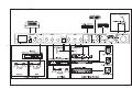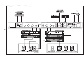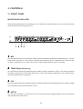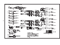
1
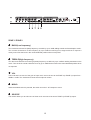
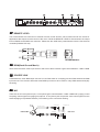
PMX2300
USER MANUAL
SAFETY PRECAUTIONS!
WARNING - TO REDUCE THE RISK OF FIRE OR ELECTRIC SHOCK, DO NOT EXPOSE THIS
UNIT TO RAIN OR MOISTURE.
Do not allow water or liquids to be spilled into this unit, if the unit has been exposed to rain or liquids, please
unplug the power cord immediately from the outlet (with DRY HANDS) and get a qualified service technician to
check. Keep this unit away from heat sources such as radiators, heat registers, stoves etc. that produce heat.
The unit contains no serviceable parts. Refer all servicing to a qualified
Service engineer, through the appropriate Phonic dealer.
CAUTION
RISK OF ELECTRIC SHOCK
DO NOT OPEN
This triangle, which appears on
your component, alerts you to
important operating and maintenance instructions in this accompanying literature.
This triangle, which appears on
your component, alerts you to the
presence of uninsulated “ dangerous voltage” inside the enclosure
that may be sufficient to constitute
a risk of shock.
CAUTION:
TO REDUCE THE RISK OF ELECTRIC SHOCK, DO NOT REMOVE COVER (OR BACK).
NO USER-SERVICEABLE PARTS INSIDE. REFER ALL SERVICING TO QUALIFIED SERVICE PERSONNEL.
Keep this unit away from dust and dirty environment. Using a soft dry brush and occasional
wipe with a damp cloth, do not use any other solvents, which may cause damage to paint or
plastic parts. Regular care and inspection will be rewarded by a long life and maximum reliability.
Your Phonic PMX 2300 was carefully packed in the factory and the packing box was designed to protect the
unit from rough handling. We recommend that you carefully examine the packaging and its contents for any
signs of physical damage, which may have occurred in transportation.
If the unit is damaged: Notify your dealer and the shipping company immediately. Claims for damage or
replacement may not be granted if fail to report it properly.
1
CONTENTS
1. INTRODUCTION ......................................................................................... 4
2. INSTALLATION........................................................................................... 5
2.1 RACK MOUNTING ............................................................................................... 5
2.2 CONNECTORS .................................................................................................... 5
2.2.1 IMPEDANCE ...................................................................................................................... 5
2.2.2 UNBALANCED/BALANCED CONNECTION .................................................................... 5
2.3 CONNECTIONS ................................................................................................... 6
2.3.1 APPLICATION 1: OFFICE ................................................................................................. 7
2.3.2 APPLICATION 2: RESTAURANT/ LAUNGE ..................................................................... 8
2.3.3 APPLICATION 3: THEATER ............................................................................................. 9
2.3.4 APPLICATION 4:HEALTH & BEAUTY CLUB ................................................................. 10
2.4 MAINS CONNECTION ....................................................................................... 11
2.4.1 SAFETY FUSE REPLACEMENT .................................................................................... 11
3. CONTROLS .............................................................................................. 12
3.1 FRONT PANEL ................................................................................................... 12
3.2 BACK PANEL ..................................................................................................... 15
4. CONNECTING LEADS ............................................................................. 17
5. SPECIFICATIONS .................................................................................... 18
2
6. SYSTEM BLOCK DIAGRAM .................................................................... 20
7. REFERENCE BOOKS .............................................................................. 21
SERVICE REQUEST FORM ........................................................................ 22
3
1. INTRODUCTION
Thank you for purchasing this 2-Zone Mixer, PMX 2300. Where there are zones, there you need a zone mixer.
This unit is custom designed to the user’s specifications. It offers you 3 outputs including 2 zones (stereo) and
1 utility (mono) and 5 inputs including 3 stereo line inputs, 1 paging microphone input and 1 emergency input.
This is very useful mixer for conference and dining facilities, such as hotels, convention centers, theaters,
auditoriums, restaurant, retail outlets, amusement parks, and even your home. All designs are for supplying
high quality and reliability to you. Enjoy it!
Please read this owner manual carefully, and look after it. If you ignore the manual and directly jump into the
unknown, there’s something might happen and makes the fool out of you. Please at least find out something
different and check if you are familiar with the mixer.
FEATURES
!
Three stereo line inputs, 1 paging microphone input, 1 emergency input, 2 stereo zone outputs, and 1
mono utility output.
!
Each zone has music source select switch, separate music level, music EQ, Mic ducking depth, and Mic
EQ controls.
!
!
!
!
!
!
!
Music EQ is +/-15dB at 100Hz and 10KHz, Mic EQ is +/-15dB at 800Hz and 8KHz.
Gain trim at Mic input with 150Hz high pass filter for best paging clarity.
Microphone paging into Zone 1 or Zone 2 can be remotely controlled.
Three stereo line inputs with individual gain trim.
Utility output is provided to serve general utility areas like toilets and foyer etc.
Utility can select from one of the music sources or paging Mic. A level control is also provided.
Remove level controls can be wired to the two stereo zones for applications that require remote control of
the music level.
!
Emergency interface connector is available for override control and audio insert of emergency message
paging. The interface will automatically route paging microphone when emergency audio is not inserted.
!
1 unit high, 19” rack mount chassis.
4
2. INSTALLATION
2.1 RACK MOUNTING
The Phonic PMX 2300 fits into standard rack, and takes one unit height of space (1 3/4"). Additional 4" depth
for the connectors on the back panel is needed. Be sure that there is enough air space around the unit for
cooling and please do not place the PMX 2300 in contact to or directly on top of high temperature devices such
as power amplifiers etc. to avoid overheating.
2.2 CONNECTORS
The PMX 2300 use XLR plug for microphone input, RCA plugs for BGM inputs, 1/4” phone plugs for emergency audio input, utility output, zone 1/zone 2 outputs, an RJ45 plug for emergency override control, an
phonix 3-pin plug for remote level control, an D-Type 9-pin for source link, and an 3.5mm mini phone plug for
paging control.
2.2.1 Impedance
The microphone input impedance is less than 2k Ohms. As standard, the outputs of the PMX 2300 are electronically balanced with output impedance lower than 100 Ohms. When driving transformer coupled loads, it
may be necessary to create 600-Ohm source impedance. For this purpose, install two 247 Ohms resistors in
series with pin 2 and 3.
2.2.2 Unbalanced/Balanced Connection
Most of the mistakes in audio installations are incorrect and defective audio connections. In order to perfectly
complete your installation, please pay special attention to the following section unless you are already familiar
with balanced/unbalanced operation.
What is an unbalanced system?
You can find this system in most of home audio-video system. It gets one conductor to carry the signal, and the
other conductor for ground. Normally for lower level signal, the signal conductor is shielded by the ground
conductor.
What is a balanced system?
Balanced system transmits the signal via 2 conductors plus one ground shielding conductor. The 2 signal
conductors carry the same signal but out of phase. For the balanced input stage, the amplifier will boost the
difference of the 2 signal conductors and remove the identical part (known as common mode signal.) of the 2
signal conductors. Because of the real signal is carried by the 2 conductors out of phase, so it is perfectly
carried to the input. At the same time, the interference occurs during transmission will be identical part (common
mode), because the signal conductors are run together, there is no chance they can be different, and all the
interference will be removed by the balanced input amplifier.
5
The difference in between 2 operations:
Because the common mode interference immunity of balanced system, and at the same time, the ground
conductor doesn’t need to carry any electrical current so that it means the ground of the 2 connected units has
identical ground level which is vital to interference free system.
Let’s look back to unbalanced system, the signal electrical current is from signal conductor to ground conductor,
and that means the ground level of 2 connected units are not identical. This means the system is much easier
to be interfered with noise.
Running long cables is easy for balanced system but difficult for unbalanced system, and lower noise is always
characterized in balanced system.
Because balanced system needs 2 conductors for signal and 1 conductor for ground, minimum 3 conductors
are needed for wiring balanced system. So dedicated system separates ground and shield as 2 conductors.
Please read following section for proper wiring balanced and unbalanced system:
2.2.3 The Correct Wiring for Balanced Operation
Always connect the main power with 3-pin plug. Make sure the power system ground is properly done. Don’t
use ground insulator plug adapter without properly connect the ground individually. This is vital to a successful
audio system connection.
Always connect the ground pin (PIN 1 in XLR) to the source unit, and disconnect this pin at the destination unit.
This connection topology is to avoid grounding loop created by both connection of signal and power ground.
Why utilize only the power ground, because it always has lower resistance and better distribution than signal
ground.
If there is hum, a very possible fault is bad grounding connection in the system. In case you can not find the
fault, try to connect the ground pin of the input connectors. If the hum is reduced or eliminated, check your
power grounding system. Special attention should be care for when two or more equipment racks are located
with some distance in between, and/or large quantity of power amplifiers are used. Check the power ground
between the racks and power distribution strips with your electricity engineer. Do make sure there is one and
only one proper ground point in the audio system (or connected video system.)
2.3 CONNECTIONS
To connect PMX 2300 with various sources and destination units, the following applications on the afterward
pages are the most common connection illustrations:
(See next page)
6
2.3.1 Application 1: Office
7
2.3.2 Application 2: Restaurant/ Launge
8
2.3.3 Application 3: Theater
9
2.3.4 Application 4:Health & Beauty Club
10
2.4 MAINS CONNECTION
Using a standard IEC receptacle and a universal main cable makes the main connection of the PMX 2300. It
meets all the requirements of the international safety certification.
Make sure all the units in the sound system are properly grounded with good connection. For your own safety,
do not remove the ground connection within the units or at the supply cable, or fail to make this connection at
all. The audio ground of the PMX 2300 is capacitor de-coupled please isolates it from the power ground. Do
not attempt to solve ground loop problem by disconnecting the power ground.
2.4.1 Safety Fuse Replacement
A safety fuse protects the unit from serious malfunction. The fuse will blow in case of power problem or short
circuits, if that happened, please replace the identical fuse only. If the new one blows right after replacement,
there must be something wrong in the unit, please call your Phonic dealer to check.
NEVER use higher or lower ratings fuses or other metal material. This will cause fire or electric shocks, which
will threaten your life and the lives of others.
11
3. CONTROLS
3.1 FRONT PANEL
MICROPHONE EQUALIZER
The equalizer (EQ) allows fine manipulation of the treble and middle frequency bands, and is particularly
useful to improve the microphone sound.
1 . MID
Turn the knob clockwise to boost 800Hz, adding fullness or adequate solidness at middle frequency. Turn the
knob counter-clockwise to cut the 800Hz, reducing the excessively hard or “telephone-like” sound, the MID
provides a 15dB boost or cut. Set the knob in the centre-detented position when not required.
2 . TREBLE(High frequency)
Turn clockwise to boost high (treble) frequency at 8KHz, adding crispness to vocals. Turn counter-clockwise
cuts 8KHz, reducing hiss or excessive sibilance, the control is providing a 15dB boost or cut. Set the knob in
the centre position when not required.
3 . VOL
This knob controls the level of balanced input microphone feeding to the selected output from +10dB to +60dB.
Turn clockwise to boost the microphone volume.
4 . DEPTH
Turn the knob clockwise to cut the zone music source and change the paging depth to let the microphone
output louder than music source.
12
ZONE 1/ ZONE 2
5 . BASS(Low frequency)
Turn clockwise to boost low (bass) frequency at 100Hz by up to 15dB, adding warmth and bass depth to music.
Turn counter-clockwise to cut low frequency by up to 15dB for reducing hum, stage rumble or to improve a
mushy sound. Set the knob in the centre-detented position when not required.
6 . TREBLE(High frequency)
Turn the knob clockwise to boost high (treble) frequency at 10KHz by up to 15dB for adding sweetness to the
music. Turn the knob counter-clockwise to cut by up to 15dB Set the knob in the centre-detented position when
not required.
7 . VOL
This knob sets how much of the gain of input music source is sent to the ZONE 1(or ZONE 2) output from 20dB to +10dB. Turn clockwise to boost the microphone volume.
8 . MONO
When the MONO switch is pressed, the switch sums the L & R outputs to mono.
9 . SOURCE
This switch allows you to select one of three music sources to be sent to ZONE 1(or ZONE 2) output.
13
UTILITY
10 . VOL
This knob sets how much of the gain of the selected input source is sent to the UTILITY output from –20dB to
+10dB.
11 . SOURCE
This switch allows you to select one of three line inputs and one microphone source to be sent to the UTILITY
output.
12 . EMERGENCY
The TRIM knob adjusts the volume of emergency audio input. While the 24VDC control circuit is activated by
external device will cut all the programs (2 zones + 1 utility) and route the audio from the emergency audio
input and the associated LED lights up. If there is no emergency audio inserted to the mixer, the input source
will be the paging microphone.
13 . POWER
Turn on or off the main power by pressing this switch. While turning on it the associated LED lights up.
14
3.2 BACK PANEL
14 . EMERGENCY
Emergency control and audio input are for emergency paging and evacuation system.
24VDC CONTROL:
A terminal block inputs accept external 24VDC regardless of the postive and negative poles to activate
the emergency function, which route the external emergency message to all outputs. It provides an
override control for emergency use.
AUDIO:
Accept an external audio input.
15 . UTILITY
The UTILITY output appears on a phone jack socket, suitable for additional MONO output use.
16 . ZONE 1/ ZONE 2
The stereo paging zone outputs include L, R channels and SUB channel for better low frequency performance.
While operating in mono mode, use the L channel.
15
17 . REMOTE LEVEL
This socket allows the connection of external volume control devices, which located at both two zones for
applications that require remote control of the music. While the REMOTE LEVEL is disconnected, the output
level of ZONE1 and ZONE2 are maximum. Please use the 10KB ohms potentiometer to be the remote level
controller(PHONIC ZCP-00).
18 . BGM(Back Ground Music)
There are three stereo music input sources and each of them includes a gain control between –10dB~+20dB.
19 . SOURCE LINK
It distributes the three BGM input sources for next PMX 2300 or accepting previous PMX 2300 three BGM
input sources. This function allows the three BGM input sources to be used for many PMX 2300 and simplify
the wiring.
20 . MIC
There are an XLR microphone input, a microphone gain control between +10dB~+60dB and a paging control
accepting control signal from paging microphone. A mini phone jack accepts the zone control signal from the
external paging mic(PHONIC ZPM-02). The following is the connection drawing:
XLR MALE PLUG
XLR FEMALE JACK
MIC SIGNAL OUTPUT
2(+)
3(-)
1(GND)
PAGING MIC
3.5
PHONE PLUG
3.5
PHONE JACK
TIP(ZONE1)
MIC CONTROL OUTPUT
RING(ZONE2)
SLEEVE(GNO)
16
PMX 2300
4. CONNECTING LEADS
17
5. SPECIFICATIONS
INPUT
Mircophone(1)
Impedance
Frequency response
Gain
EIN
CMRR
Filter
Balanced, nominal at –60dBu.
2K ohms
150Hz~20KHz, +0, -1dB
+15~+60dB
-128dBu
100dB @maximum gain
RF & HPF, 150Hz @-3dB, 18dB/oct
Stereo BGM Input(3)
Unbalanced, stereo line level(-10dBV)
Impedance
Frequency response
Gain
Filter
Emergency Audio(1)
Impedance
Frequency response
Gain
Filter
40K ohms
44Hz~20KHz, +0, -1dB
0~+20dB
RF & HPF, 50KHz & 30Hz @-3dB, 18dB/oct
Unbalanced line level
14K ohms
150Hz~20KHz, +0, -1dB
-10dB~+10dB
RF & HPF, 30KHz & 150Hz @-3dB, 18dB/oct
OUTPUT
Stereo Zone output (2)
Microphone Equalizer
Music Equalizer
Impedance
Frequency response
Gain
Paging Override Depth
Crosstalk
Filter
Utility output (1)
Impedance
Frequency response
Gain
Balanced
HF @ 10KHz, shelving, +/-12dB
MF @ 800Hz, peak/dip, +/-12dB
HF @ 10KHz, shelving +/-12dB
LF @ 100Hz, shelving +/-12 dB
100 ohms
45Hz~20KHz, +0, -1dB
-20~+10dB
Cut~-10dB
-65dB between any 2 output
RF & HPF, 50KHz & 30Hz @ -3dB, 18dB/oct
Unbalanced
100 ohm
45Hz~20KHz, +0, -1dB
-20~+10dB
18
Crosstalk
Filter
CONTROLS
Front Panel Control
Rear Panel Control
Panic Override (1)
-65dB between any 2 output
RF & HPF, 30KHz & 30Hz @ -3dB, 18dB/oct
EQ, Override depth presets, Level, Utility BGM selector
Gain, Microphone Remote Control (1), 2 functions, paging to zone
1 and/or 2. Contact closures or open collector logic control
Zone Remote Control (2), BGM Level
+24VDC
POWER
Mains power
Power Consumption
Fuse
Mains connector
100~120, 200~240VAC, 50~60Hz
10 watts
~100VAC FUSE 500mA, ~110-120VAC FUSE 500mA,
~220-240VAC FUSE T315mA
3 pins, Hot, neutral & Ground
19
6. SYSTEM BLOCK DIAGRAM
20
7. REFERENCE BOOKS
Phonic recommends the following books for those interested in advanced audio engineering and sound system operation:
!
!
Sound System Engineering by Don and Carolyn Davis, Focal Press, ISBN: 0-240-80305-1
Sound Reinforcement Handbook by Gary D. Davis, Hal Leonard Publishing Corporation, ISBN: 0-88188900-8
!
!
!
!
Audio System Design and Installation by Philip Giddings, Focal Press, ISBN: 0-240-80286-1
Practical Recording Techniques by Bruce and Jenny Bartlett, Focal Press, ISBN: 0-240-80306-X
Modern Recording Techniques by Huber & Runstein, Focal Press, ISBN: 0-240-80308-6
Sound Advice – The Musician’s Guide to the Recording Studio by Wayne Wadham, Schirmer Books,
ISBN: 0-02-872694-4
!
Professional Microphone Techniques by David Mills Huber, Philip Williams. Hal Leonard Publishing
Corporation, ISBN: 0-87288-685-9
!
Anatomy of a Home Studio: How Everything Really Works, from Microphones to Midi by Scott Wilkinson,
Steve Oppenheimer, Mark Isham. Mix Books, ISBN: 091837121X
!
Live Sound Reinforcement: A Comprehensive Guide to P.A. and Music Reinforcement Systems and Technology by Scott Hunter Stark. Mix Books, ISBN: 0918371074
!
Audiopro Home Recording Course Vol 1: A Comprehensive Multimedia Audio Recording Text by Bill
Gibson. Mix Books, ISBN: 0918371104
!
Audiopro Home Recording Course Vol 2: A Comprehensive Multimedia Audio Recording Text by Bill
Gibson. Mix Books, ISBN: 0918371201
21
COPYMASTER DO NOT REMOVE
NOTE! This sheet is your Copymaster. Please duplicate on photocopier when needed.
Service Request Form
Please complete this form and send it to Phonic before returning the unit. Attach duplicate
to the returned unit.
NAME__________________________ TELEPHONE_____________________________
ADDRESS _______________________________________________________________
_______________________________________________________________
_______________________________________________________________
_______________________________________________________________
MODEL No.______________________ SERIAL No.______________________________
PURCHASED FROM____________________________ DATE______________________
Please tick appropriate box
REPLACEMENT PACKING REQUIRED
YES
1. Describe symptoms of malfunction.
2. Which part(s) exhibit(s) the problem?
3. Under what conditions does the problem occur?
a.
All the time
b.
After a while
c.
At high signal levels
d.
At high temperatures
e.
Other(please explain)
Is the fault:
Permanent
Intermittent
4. What did you do to isolate the problem to this unit?
5. Further comments.
22
NO